电源转换器使用说明书
(完整版)RS-232转RS-485转换器使用说明书
RS-232/RS-485转换器使用说明书一、产品介绍HEXIN-III型转换器是RS-232与RS-485之间的双向接口的转换器、应用于主控机之间,主控机与单片机或外设之间构成点到点,点到多点远程多机通讯网络,实现多机应答通讯,广泛地应用于工业自动化控制系统、一卡通、门禁系统、停车场系统、自助银行系统、公共汽车收费系统。
饭堂售饭系统、公司员工出勤管理系统、公路收费站系统等等。
HEXIN-III型转换器、能够将RS-232串行口的TXD和RXD信号转换成两线平衡半双工的RS-485信号。
无需未接外接电源,可直接从RS-232端口的3脚窃电,同时由7脚请求发送(RTS),4脚数据终端准备好(DTR)给HEXIN-III 辅助供电,自动的流控使你不必重新设置,硬件与安装使用非常简单。
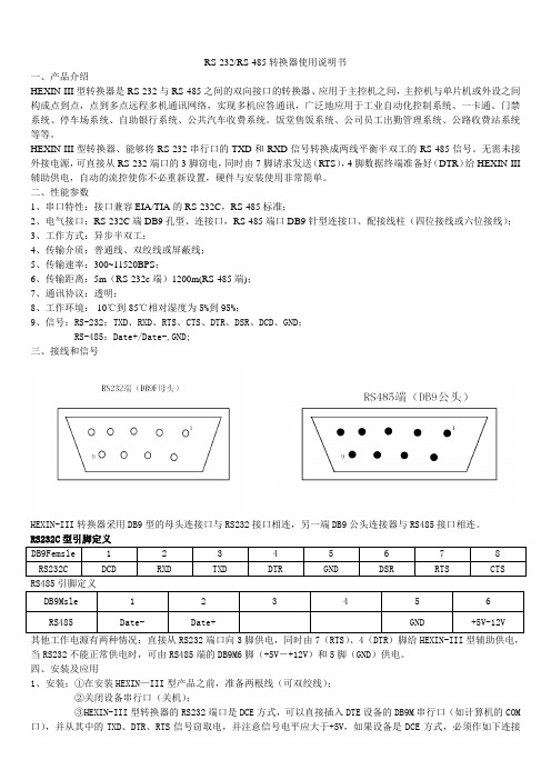
二、性能参数1、串口特性:接口兼容EIA/TIA的RS-232C,RS-485标准;2、电气接口:RS-232C端DB9孔型、连接口,RS-485端口DB9针型连接口、配接线柱(四位接线或六位接线);3、工作方式:异步半双工;4、传输介质:普通线、双绞线或屏蔽线;5、传输速率:300~11520BPS;6、传输距离:5m(RS-232c端)1200m(RS-485端);7、通讯协议:透明;8、工作环境:-10℃到85℃相对湿度为5%到95%;9、信号:RS-232:TXD、RXD、RTS、CTS、DTR、DSR、DCD、GND;RS-485:Date+/Date-,GND;三、接线和信号HEXIN-III转换器采用DB9型的母头连接口与RS232接口相连,另一端DB9公头连接器与RS485接口相连。
RS232C型引脚定义DB9Femsle 1 2 3 4 5 6 7 8RS232C DCD RXD TXD DTR GND DSR RTS CTS RS485引脚定义DB9Msle 1 2 3 4 5 6 RS485 Date- Date+ GND +5V-12V其他工作电源有两种情况:直接从RS232端口向3脚供电,同时由7(RTS)、4(DTR)脚给HEXIN-III型辅助供电,当RS232不能正常供电时,可由RS485端的DB9M6脚(+5V―+12V)和5脚(GND)供电。
Murata 电源转换器 D1U54P-W-1200-12-HC4PC 用户指南说明书

/supportFor full details go to /rohsORDERING GUIDE Part NumberPower Output High Line AC Power Output Low Line AC Main Output Standby Output Airfl ow D1U54P-W-1200-12-HC4PC 1200W 1100W 12Vdc3.3Vdc Back to front D1U54P-W-1200-12-HA4PC 5Vdc D1U54P-W-1200-12-HC3PC 3.3Vdc Front to backD1U54P-W-1200-12-HA3PC5Vdc1 Refer to page 5 for alternate connector pinout assignment (HxxC).2Refer to page 7 for alternate input connector (HxxxKC).3The HCxxC variants are certifi ed for compliance to 80 PLUS ® Platinum effi ciency requirements.INPUT CHARACTERISTICS ParameterConditionsMin.Nom.Max.Units Input Voltage Operating Range 90115/230264Vac Input Frequency 4750/6063Hz Turn-on Input Voltage Ramp up 808589Vac Turn-off Input VoltageRamp down 657378Maximum current at Vin = 100Vac 1100W12Arms Inrush Current Cold start between 0 to 200msec 25ApkPower FactorAt 230Vac, full load 0.99Effi ciency (230Vac) excluding fan load 20% load90%50% load94100% load 91OUTPUT VOLTAGE CHARACTERISTICS NominalOutput VoltageParameter Conditions Min.Typ.Max.Units 12V Nominal Output Voltage 12VdcOutput Set Point Accuracy 50% load; Tamb =25°C -0.5+0.5%Line and Load Regulation-1.0+1.0Ripple Voltage & Noise 420MHz Bandwidth150mV p-p Output Current (230Vac)5100A Output Current (120Vac)590Load Capacitance30,000μF 3.3VSBNominal Output Voltage 3.3Vdc Output Set Point Accuracy 50% load; Tamb = 25°C -0.5+0.5%Line and Load Regulation-1.0+1.0Ripple Voltage & Noise 420MHz Bandwidth75mV p-p Output Current 3A Load Capacitance1000μF 5VSBNominal Output Voltage 5.0Vdc Output Set Point Accuracy 50% load; Tamb = 25°C -0.5+0.5%Line and Load Regulation-1.0+1.0Ripple Voltage & Noise 420MHz Bandwidth75mV p-p Output Current 03A Load Capacitance1000μF4Ripple and noise are measured with 0.1 μF of ceramic capacitance and 10 μF of tantalum capacitance on each of the power supply outputs. A short coaxial cable with 50Ω scope termination is used.FEATURES⏹1200W output power ⏹80 PLUS ® Platinum effi ciency ⏹12V main output⏹3.3V and 5V standby output⏹1U height: 2.15" x 12.65" x 1.57"⏹28 Watts per cubic inch density⏹N+1 redundancy capable,including hot plugging (up to 8 in parallel) ⏹Active current sharing on 12V main output; ORing FET ⏹Overvoltage, overcurrent, overtemperature protection ⏹Internal cooling fan (variable speed) ⏹PMBus™ / I²C interface with status indicators ⏹RoHS compliantPRODUCT OVERVIEWThe D1U54P-W-1200-12-HxxxC series are 80 PLUS ® Platinum effi ciency 1200 watt, power factor corrected front endsupplies with a 12V main output and a 3.3V (3A) or 5V (3A) standby. They have active current sharing and up to 8 supplies may be operated in parallel. The supplies may be hot plugged, they recover from overtemperature faults, and have status LEDs on their front panel in addition to logic and PMBus™ status signals. Their low profi le 1U package and >28W/cubic inch power density make them ideal for delivering reliable, effi cient power to servers, workstations,storage systems and other 12V distributed power systems.CBTest Certi fi cate and Test ReportPM/en/3d/acdc.html /en/3d/acdc.html /en/3d/acdc.html /en/3d/acdc.html /en/3d/acdc.html /en/3d/acdc.html Available now at/en/3d/acdc.htmlContact Murata Sales for availability of variants with this connector confi guration.Murata Power Solutions, Inc. makes no representation that the use of its products in the circuits described herein, or the use of other technical information contained herein, will not infringe upon existing or future patent rights. The descriptions contained herein do not imply the granting of licenses to make, use, or sell equipment constructed in accordance therewith. Specifi cations are subject to change without notice. © 2014 Murata Power Solutions, Inc.Murata Power Solutions, Inc. 11 Cabot Boulevard, Mansfi eld, MA 02048-1151 U.S.A.ISO 9001 and 14001 REGISTEREDThis product is subject to the following operating requirementsand the Life and Safety Critical Application Sales Policy: Refer to: /requirements/。
电子产品EPM Serie 2-3W宽输入范围DC-DC转换器说明说明书

Selection Guide 2:1 2W OutputMODEL NUMBER INPUTVOLTAGE(VDC)OUTPUTVOLTAGE(VDC)OUTPUTCURRENT(mA)INPUT6CURRENT(mA) EFF(%)7ISOLATION8(VDC)PACKAGEFULLLOADNOLOADPM22-01(-3K) 4.5-9 3.3 500 465 50 71 1500(3000) H PM22-02(-3K) 4.5-9 5 400 555 50 72 1500(3000) H PM22-03(-3K) 4.5-9 9 222 519 50 77 1500(3000) H PM22-04(-3K) 4.5-9 12 150 480 50 75 1500(3000) H PM22-05(-3K) 4.5-9 15 120 456 50 79 1500(3000) H PM22-06(-3K) 9-18 3.3 500 205 30 67 1500(3000) H PM22-07(-3K) 9-18 5 400 219 20 76 1500(3000) H PM22-08(-3K) 9-18 9 222 225 20 74 1500(3000) H PM22-09(-3K) 9-18 12 168 209 20 80 1500(3000) H PM22-10(-3K) 9-18 15 133 209 20 80 1500(3000) H PM22-11(-3K) 9-18 24 83 213 20 78 1500(3000) H PM22-12 9-18 +/-5 +/-200 225 20 74 1500 H PM22-13 9-18 +/-12 +/-83 225 20 74 1500 H PM22-14 9-18 +/-15 +/-67 225 20 74 1500 H PM22-15(-3K) 18-36 3.3 500 93 12 74 1500(3000) H PM22-16(-3K) 18-36 5 400 110 12 76 1500(3000) H PM22-17(-3K) 18-36 9 222 111 13 75 1500(3000) H PM22-18(-3K) 18-36 12 168 104 11 80 1500(3000) H PM22-19(-3K) 18-36 15 133 105 11 79 1500(3000) H PM22-20(-3K) 18-36 24 83 107 11 78 1500(3000) H PM22-21 18-36 +/-5 +/-200 112 12 74 1500 H PM22-22 18-36 +/-12 +/-83 112 12 74 1500 H PM22-23 18-36 +/-15 +/-67 112 12 74 1500 H PM22-24(-3K) 36-75 3.3 500 46 8 75 1500(3000) H PM22-25(-3K) 36-75 5 400 56 8 74 1500(3000) H PM22-26(-3K) 36-75 9 222 55 8 75 1500(3000) H PM22-27(-3K) 36-75 12 168 51 8 82 1500(3000) H PM22-28(-3K) 36-75 15 133 51 8 82 1500(3000) H PM22-29(-3K) 36-75 24 83 54 8 77 1500(3000) H PM22-30 36-75 +/-5 +/-200 56 8 74 1500 H PM22-31 36-75 +/-12 +/-83 54 8 77 1500 H PM22-32 36-75 +/-15 +/-67 54 8 77 1500 H Note: Other input to output voltages may be available. Please contact factory.FOR EXAMPLE: PM22-12(H PACKAGE 2W SINGLE OUTPUT 1500VDC ISOLATION)PM22-11(-3K)(H PACKAGE 2W SINGLE OUTPUT 3000VDC ISOLATION)6NOMINAL INPUT VOLTAGE.7 NOMINAL INPUT VOLTAGE, FULL LOAD.Selection Guide 2:1 2W OutputMODEL NUMBERINPUTVOLTAGE(VDC)OUTPUTVOLTAGE(VDC)OUTPUTCURRENT(mA)INPUT9CURRENT(mA) EFF(%)10ISOLATIO N11(VDC)PACKAGEFULLLOADNOLOADPM22-33 4.5-9 3.3 500 465 50 71 1500 J PM22-34 4.5-9 5 400 555 50 72 1500 J PM22-35 4.5-9 9 222 519 50 77 1500 J PM22-36 4.5-9 12 150 500 50 72 1500 J PM22-37 4.5-9 15 120 500 50 72 1500 J PM22-389-18 3.3 500 205 30 67 1500 J PM22-399-18 5 400 219 20 76 1500 J PM22-409-18 9 222 225 20 74 1500 J PM22-419-18 12 168 213 20 78 1500 J PM22-429-18 15 133 213 20 78 1500 J PM22-439-18 24 83 213 20 78 1500 J PM22-4418-36 3.3 500 93 12 74 1500 J PM22-4518-36 5 400 112 12 74 1500 J PM22-4618-36 9 222 111 13 75 1500 J PM22-4718-36 12 168 107 11 78 1500 J PM22-4818-36 15 133 107 11 78 1500 J PM22-4918-36 24 83 107 11 78 1500 J PM22-5036-75 3.3 500 52 8 67 1500 J PM22-5136-75 5 400 56 8 74 1500 J PM22-5236-75 9 222 55 8 75 1500 J PM22-5336-75 12 168 51 8 82 1500 J PM22-5436-75 15 133 51 8 82 1500 J PM22-5536-75 24 83 54 8 77 1500 J Note: Other input to output voltages may be available. Please contact factory.9NOMINAL INPUT VOLTAGE.10 NOMINAL INPUT VOLTAGE, FULL LOAD.Selection Guide 4:1 2W OutputMODEL NUMBERINPUTVOLTAGE(VDC)OUTPUTVOLTAGE(VDC)OUTPUTCURRENT(mA)INPUT12CURRENT(mA) EFF(%)13ISOLATION14(VDC)PACKAGEFULLLOADNOLOADPM24-01(-3K) 9-36 3.3 500 205 30 70 1500(3000) H PM24-02(-3K) 9-36 5 400 222 20 74 1500(3000) H PM24-03(-3K) 9-36 9 222 225 20 74 1500(3000) H PM24-04(-3K) 9-36 12 165 213 20 78 1500(3000) H PM24-05(-3K) 9-36 15 133 213 20 78 1500(3000) H PM24-06(-3K) 9-36 24 83 213 20 78 1500(3000) H PM24-07 9-36 +/-15 +/-67 220 20 76 1500 H PM24-08(-3K) 18-75 3.3 500 98 12 70 1500(3000) H PM24-09(-3K) 18-75 5 400 112 12 74 1500(3000) H PM24-10(-3K) 18-75 9 222 112 13 74 1500(3000) H PM24-11(-3K) 18-75 12 165 107 11 78 1500(3000) H PM24-12(-3K) 18-75 15 133 107 11 78 1500(3000) H PM24-13(-3K) 18-75 24 83 107 11 78 1500(3000) H Note: Other input to output voltages may be available. Please contact factory.12NOMINAL INPUT VOLTAGE.13 NOMINAL INPUT VOLTAGE, FULL LOAD.Selection Guide (4) 2:1 3W OutputMODEL NUMBERINPUTVOLTAGE(VDC)OUTPUTVOLTAGE(VDC)OUTPUTCURRENT(mA)INPUT15CURRENT(mA) EFF(%)16ISOLATION17(VDC)PACKAGEFULLLOADNOLOADPM32-01(-3K) 4.5-9 3.3 700 641 100 72 1500(3000) H PM32-02(-3K) 4.5-9 5 600 800 100 75 1500(3000) H PM32-03(-3K) 4.5-9 9 333 778 100 77 1500(3000) H PM32-04(-3K) 4.5-9 12 250 779 100 77 1500(3000) H PM32-05(-3K) 4.5-9 15 200 779 100 77 1500(3000) H PM32-06 4.5-9 +/-5 +/-300 789 100 76 1500 H PM32-07 4.5-9 +/-12 +/-125 779 100 77 1500 H PM32-08 4.5-9 +/-15 +/-100 779 100 75 1500 H PM32-09(-3K) 9-18 3.3 700 263 45 73 1500(3000) H PM32-10(-3K) 9-18 5 600 336 45 74 1500(3000) H PM32-11(-3K) 9-18 9 333 320 45 78 1500(3000) H PM32-12(-3K) 9-18 12 250 320 45 78 1500(3000) H PM32-13(-3K) 9-18 15 200 310 45 81 1500(3000) H PM32-14 9-18 +/-5 +/-300 324 45 77 1500 H PM32-15 9-18 +/-12 +/-125 320 45 78 1500 H PM32-16 9-18 +/-15 +/-100 320 45 78 1500 H PM32-17(-3K) 18-36 3.3 700 128 20 75 1500(3000) H PM32-18(-3K) 18-36 5 600 162 20 77 1500(3000) H PM32-19(-3K) 18-36 9 333 152 20 82 1500(3000) H PM32-20(-3K) 18-36 12 250 158 20 79 1500(3000) H PM32-21(-3K) 18-36 15 200 154 20 81 1500(3000) H PM32-22 18-36 +/-5 +/-300 162 20 77 1500 H PM32-23 18-36 +/-12 +/-125 158 20 79 1500 H PM32-24 18-36 +/-15 +/-100 158 20 79 1500 H PM32-25(-3K) 36-75 3.3 700 66 12 73 1500(3000) H PM32-26(-3K) 36-75 5 600 81 12 77 1500(3000) H PM32-27(-3K) 36-75 9 333 80 12 78 1500(3000) H PM32-28(-3K) 36-75 12 250 79 12 79 1500(3000) H PM32-29(-3K) 36-75 15 200 76 12 82 1500(3000) H PM32-30(-3K) 36-75 24 125 79 12 79 1500(3000) H PM32-31 36-75 +/-5 +/-300 81 12 77 1500 H PM32-32 36-75 +/-12 +/-125 79 12 79 1500 H PM32-33 36-75 +/-15 +/-100 79 12 79 1500 H15NOMINAL INPUT VOLTAGE.16 NOMINAL INPUT VOLTAGE, FULL LOAD.Input Fuse Selection Guide4.5-9VINPUT VOLTAGE(VDC) 9-18V(9-36V) INPUT VOLTAGE(VDC) 18-36V(18-75V) INPUT VOLTAGE(VDC)36-75V INPUT VOLTAGE(VDC) 2000mA Slow-Blow Type1000mA Slow-Blow Type500mA Slow-Blow Type 200mA Slow-Blow TypeNote: Certain applications may require the installation of external fuse in front of the input.EPM 2-3 Watt Series Application Notes: EXTERNAL CAPACITANCE REQUIREMENTS:No external capacitance is required for operation of the EP 2-3 Watt series.To meet the reflected ripple requirements of the converter, an input impedance of less than 0.5 ohm from DC to 100KHz is required.External output capacitance is not required for operation, however it is recommended that 10uF tantalum and 0.1uF ceramic DC-DCCONVERTER+Vin-Vin+Vout-VoutOUTPUTINPUT。
转换器使用说明书

转换器使用说明书亲爱的用户,感谢您选择本公司的产品和服务。
对技术完美性的追求是我们的目标,我们的理念是产品不求多,只求精。
请您在使用本机前详细阅读此说明书,以便方便您安装使用。
注意:本手册未经本公司的许可,不得任意复制、拷贝、翻译或以其他形式进行发送。
本手册所提及的商标和名称皆属本公司所有。
未经本公司许可而对产品及本说明书进行修改所造成的产品功能不实现、损伤或对其他产品、人造成的影响,本公司将不负任何责任。
对于以合法渠道取得本公司产品的用户,本公司将提供三个月保换、一年保修的服务,但不包括操作不当,人为原因的故障及伤害。
本手册若有任何内容修改或变更,将不另行通知。
XX年X月版本:V4.0一、系统简介XX转换器型设备1~8条E1电路点对点地传输以太网MAC帧数据,设计最高传输速率可达16.384Mbps。
设备不仅提供了线路侧、以太网侧完备的告警指示,而且提供了包括线路的误码率统计,以太网数据流量统计等全面的管理信息,便于构建可统一运营的接入网。
二、技术特性1,实现1-8路E1通道承载100M以太网数据。
2,以太网接口标准的MII接口,只支持100M,全双工工作模式;内置流量统计,可汇报给网管以太网收发的流量统计和错包率等信息;对超长、超短和CRC错包进行过滤;最大支持2036字节的超长包;支持PAUSE流量控制功能;可通过以太网进行管理(可选)3,线路接口1-8路E1通道。
必须成对使用,但可以不对称使用;自动检测可用通道数目,该通道数据也可以通过网管关断;具有AIS、LOS、LOF和误码率告警,其中误码率的具体数据可以通过网管查询;误码关断及误码门限可由网管设置;支持远端环回,支持线路通道误码检测(利用HDLC控制帧);发起远端环回时,禁止向以太网侧发送数据;可检测外部E1环回,禁止向以太网侧发送数据;XX码型4,网管支持XX网管。
可通过以太网进行管理;8bits设备地址输入,最多统一管理256个设备网管信息全面,包括本端和远端的各E1线路状态,以太网端口信息和流量统计。
电源转换器产品说明说明书
TABILITY50 dB-50 dB0 dB 180°-180°0°100HZ1KhZ10KH 100KHZFREQUENCYPhase GainAll specifications are typical @+25°C with nominal input voltage under full output load conditions, unless otherwise noted. Specifications subject to change without notice./powerconversionIndustrial & military grade high density DC to DC converters4-40 UNC-2B THRU 4 PLACES-C Option-B Option-A Option.040 DIA ± .005.50 / 12.7 MIN..30 / 7.6.38 / 9.7marking surfacebase plate.50 / 12.7MIN..15 / 3.81234+ V IN IN RTN TRIM TTL PAR POWER GOOD+ S 056SYNC7891011+ OUT - OUT - STolerances:inches -x.xx x.xxx= ±0.03= ±0.015mm -x.xx.xx = ±0.8= ±0.401111 Knox Street TorranceCA 90502USATel: +1 310 202 8820*********************All specifications are typical @+25°C with nominal input voltage under full output load conditions, unless otherwise noted. Specifications subject to change without notice./powerconversionPerformance characteristics50 dB-50 dB0 dB How to Order:50 T M / 5 / 15 - A Phase GainNB50TT RIPLEOUTPUT3/powerconversionIndustrial & military grade high density DC to DC converters.125 / 32.875 / 1.275 / 32.391.450 / 36.831.100 / 27.94.925 / 23.504-40 UNC-2B THRU 4 PLACES1.875 / 47.632.00 / 50.8.975 / 24.77 -C Option-B Option-A Option-A Option.040 DIA ± .005.50 / 12.7 MIN..30 / 7.6.38 / 9.7marking surfacebase plate.50 / 12.7MIN..15 / 3.81234+ V IN IN RTN TRIM TTL Inches / MillimetersPOWER GOOD+ S.825 / 20.96.675 / 17.15.375 / 9.53.750 / 19.051.125 / 28.586SYNC7891011+ MAIN OUT MAIN RTN- S.125 / 3.181.625 / 41.28.125 / 3.183.00 / 7121314+ AUX OUT AUX COM - AUX OUT .575 / 14.61.400 / 10.161.875 / 47.63Tolerances:inches -x.xx x.xxx= ±0.03= ±0.015mm -x.xx.xx = ±0.8= ±0.40DCTODC C ONVERTERSAll specifications are typical @+25°C with nominal input voltage under full output load conditions, unless otherwise noted. Specifications subject to change without notice./powerconversionPerformance characteristics50S NB100NB150Performance CharacteristicsIX. TTL Turn OnIII. Efficiency vs. Input VoltageII. Efficiency vs. Output PowerVI. Input Transient ResponseV. Load Transient ResponseIV. Output Voltage RippleVII. Input Inrush CurrentVIII. Input Current RippleX. TTL Turn-offXI. Turn-onXII. Turn-off / Hold-up TimeInput Voltage E f f i c i e n c y100%80%60%40%20%0%90%85%80%75%70%65%60%20% 40% 60% 80% 100%90%85%80%75%70%65%60%14 18 22 26 30 34 38Output Load Input Voltage20 m V /d i vTime: 2 μS/div Time: 0.5 mS/divTime: 0.2 mS/div20 V /d i v 0.2 V /d i vTime: 50 μS/div Time: 2 μS/div Time: 0.5 mS/div20 A /d i v 20 V /d i v0.2 A /d i v5 V /d i v 2 V /d i v10 V /d i v 5 V /d i vTime: 100 μS/divTime: 0.5 mS/divTime: 100 μS/div 5 V /d i v 2 V /d i v5 V /d i v 20 V /d i vV = 28 Vdc, V = 15 Vdc, I = 3.3 AV = 28 Vdc, V = 15 Vdc50 - 100% Step LoadOutput CurrentOutput VoltageOutput VoltageInput VoltageV = 15 Vdc, I = 3.3 A14 - 40V TransientV = 28 Vdc, V = 15Vdc, I = 3.3 AInput VoltageInput CurrentV = 28 Vdc, V = 15 Vdc, I = 3.3 AV = 28 Vdc, V = 15 Vdc, I = 3.3 ATTL SignalOutput VoltageV = 28 Vdc, V = 5 Vdc, I = 3.3 AOutput VoltageInput Voltage V = 28 Vdc, V = 15 Vdc, I = 3.3 AInput VoltageOutput VoltageV = 28 Vdc, V = 15 Vdc, I = 3.3 AOutput VoltageTTL Signal 3.3V5V12V24V15V28V 24V 15V 12V 5V 3.3V2V15V 12V10 11 12 13 4028V2V5/powerconversionNBF50 EMI filtersHow to Order:Inches / Millimeters .125 / 3.181.625 / 41.281.375 / 34.93.625 / 15.88.875 / 22.23.125 / 3.184-40 UNC-2B THRU 4 PLACES 1.50 / 38.11.050 / 26.671.375 / 34.93.450 / 11.43.125 / 3.18-C Option-B Option-A Option-A Option.040 DIA ± .005.50 / 12.7 MIN..30 / 7.6.38 / 9.7marking surfacebase plate.50 / 12.7MIN..15 / 3.81234+ IN- IN+ OUT - OUT1.75 / 44.528V in - 50 wattsMIL-STD-461D, CE102With NBF50Without NBF50CASE DRA WING0.01 0.02 0.04 0.06 0.8 0.1 0.2 0.4 0.6 0.8 1 2 4 6 8 10120100806040200-201201008060402000.03 0.04 0.06 0.08 0.1 0.2 0.4 0.6 0.8 1 2 4 6 8 10dBuA dBuV kHzMHzTolerances:inches -mm-x.xx x.xxx x.x x.xx= ±0.03= ±0.015= ±0.8= ±0.40NBF50>> 181111 Knox Street TorranceCA 90502USATel: +1 310 202 8820*********************All specifications are typical @+25°C with nominal input voltage under full output load conditions, unless otherwise noted. Specifications subject to change without notice.6/powerconversionEaton is a registered trademark. All other trademarks are property of their respective owners.Eaton1000 Eaton Boulevard Cleveland, OH 44122 United States © 2017 EatonAll Rights Reserved March, 2017ore-mail:*******************。
APC 电源冗余转换器 说明书

4、 连接 PowerChute 电缆 • 当你准备安装 PowerChuteplus 时,请将 PowerChuteplus 通讯电缆安装在冗余开
关的服务器端口和服务器的串口之间。
个合格的电工能够将内部四针蓝色的阴极连接器连接到紧急停电系统。这样一来,紧
急停电系统就可以运行了。只要系统启动,UPS 系统都会停止供电。
注意 紧急停电系统接口是一个安全低压电路,只可以与其他安全低压电路连接。紧 急停电系统是一个控制电路,不需要有源电压。所用闭环电路应通过与市电隔 离的开关或者继电器实现。使用其他非闭环电路会损害冗余开关。
前部面板用户操作 用户操作设置面板位于冗余开关的前部,便于操作。
ΟΟΟ功能选择 LED 指示灯 这三个绿色的 LEDS 显示用户选择的状态参数,使用左边的键可以选择以上所列 5 种 用户设置。 Ο 功能状态 LED 指示灯 绿色的功能状态 LED 显示用户所选的功能状态。使用左边的键可以进行选择。
AC 电源 LED 指示灯
电源,连接安装完毕后再接通电源。 • 在处理任何金属连接器之前,应该先断开电源。 • 尽量使用一只手连接或者断开信号电缆,以免碰触两极,遭到电击。 • 将设备连接到三相 AC 电源(火,零和地)。插座应该有适宜的电路保护装置(保
险丝和电路断路器)。和其他类型的插座相连可能会引起电击危险。 注意:断电安全 • 断电步骤:按住 UPS 的电源开关,保持一秒钟以上,关掉 UPS 电源。然后从 AC
如果 PowerChute plus多次显示:self test failed: invalids test, UPS-A 失去了输出电压 功能,请通过 PowerChute plus做自检,如果自检失败,则按照随电源附带的 SmartUPS 快速参考指示排除故障,如需协助请遵照服务部分指示。
莫仕20(25)W系列AC DC电源转换器说明书
20(25)W,AC-DC converterFEATURES●Universal input range:85~264V AC,100~370VDC ●Regulated output,low ripple and noise ●Efficiency up to 87%●Over-current,shortcircuitand over-voltageprotection●Plastic case,meets UL94V-0●IEC60950,UL60950,EN60950Approval●PCB mounting,Chassis mounting,DIN-Rail mountingCBRoHSLH 20-25series -----a compact size power converter offered by Mornsun.It features universal input voltage,taking both DC and AC input voltage,low power consumption,high efficiency,high reliability,safer isolation.It offers good EMC performance,which meetIEC/EN61000-4,CISPR22/EN55022,UL60950and EN60950standards,and it’s widely used in industrial,office and civil applications.For harsh EMC environment,the application circuit in the datasheet is strongly recommended.Selection GuideCertificationPart No.*Output PowerNominal Output Voltage andCurrent Efficiency (230V AC,%/Typ.)Max.CapacitiveLoad(µF)(Vo1/Io1)(Vo2/Io2)Vo1Vo2UL/CE/CBLH20-10B0313.53W3.3V/4100mA --7448000--LH20-10B0517.5W5V/3500mA --7812240--LH20-10B0920W9V/2100mA --807200--LH20-10B1212V/1600mA --825400--LH20-10B1515V/1300mA --832720--LH20-10B2424V/850mA --851840----LH20-10A05+5V/2000mA -5V/2000mA 7580008000LH20-10A12+12V/830mA -12V/830mA 82960960LH20-10A15+15V/650mA -15V/650mA 83880880LH20-10C0505-055V/2500mA ±5V/500mA 74112004480LH20-10C0512-045V/2000mA ±12V/400mA 75160001600LH20-10C0515-035V/2000mA ±15V/300mA 7613520370LH20-10C0524-025V/2000mA ±24V/200mA 7711200370LH20-10D0512-065V/2500mA 12V/600mA 75324003250LH20-10D0515-055V/2500mA 15V/500mA 76280001980LH20-10D0524-035V/2500mA 24V/300mA7728000720UL/CE/CBLH25-10B0313.53W 3.3V/4100mA --7448000--LH25-10B0520.5W5V/4100mA --7912240--LH25-10B0925W 9V/2500mA --815600--LH25-10B1212V/2100mA --835400--LH25-10B1515V/1600mA --842400--LH25-10B2424V/1100mA --851440--LH25-10B4848V/500mA--87500--Note:*About LH20-10AXX,use both positive and negative output as sampling feedback;and all others use Vo1as sampling feedback.Input SpecificationsItemOperating Conditions Min.Typ.Max.Unit Input Voltage Range AC input 85--264V AC DC input100--370VDC Input frequency 47--63HzInput current 115V AC ----0.6A 230V AC ----0.34Inrush current 115V AC --16--230V AC--30--Leakage current0.3mA RMS typ./230V AC/50Hz Recommended External InputFuse(Special package series include fuse) 3.15A/250V,slow fusing Hot PlugUnavailableOutput SpecificationsItemOperating Conditions Min.Typ.Max.UnitOutput Voltage Accuracy Main circuit --±2--%Line RegulationFull loadMain circuit --±0.5--Auxiliary circuit --±1.5--Load Regulation10%-100%loadSingle output--±1--Dual output(balanced load)--±2--Isolated triple output (balanced load)Main circuit --±3--Auxiliary circuit --±5--Isolated and separated twin output (balanced load)Main circuit --±3--Auxiliary circuit--±5--Ripple &Noise*20MHz bandwidth (peak-peak value)--50100mV Temperature Coefficient Main circuit--±0.02--%/°C Short Circuit Protection Continuous,self-recovery Over-current Protection≥110%Io self-recoveryOver-voltage ProtectionMain circuit3.3/5VDC Output ≤7.5VDC 9VDC Output≤13VDC 12/15VDC Output ≤20VDC 24VDC Output ≤30VDC 48VDC Output≤60VDCMin.LoadSingle output models0----%Dual output models (balanced load)10----Isolated and separated twin output (balanced load)10----Isolated triple output (balanced load)10----Hold-up Time115V AC input --15--ms 230V AC input--80--Note:*Ripple and noise are measured by “parallel cable”method,please see AC-DC Converter Application Notes for specific operation.General SpecificationsItemOperating Conditions Min.Typ.Max.Unit Isolation VoltageInput-outputTest time:1min 3000----V ACOperating Temperature LH20-10A/C/D series -25--+70°C LH20(25)-10B series -40--+70Storage Temperature LH20-10A/C/D series -25--+85LH20(25)-10B series-40--+85Storage Humidity----95%RHWelding Temperature Wave-soldering 260±5℃;time:5~10s Manual-welding360±10℃;time:3~5sSwitching Frequency--65--kHzPower Derating-25℃~-10℃(LH20-10A/C/D Series)2.0-----40℃~-10℃(LH20(25)-10B Series) 2.0----+50℃~+70℃(LH25-10B Series)3.0----+55℃~+70℃(LH20-10A/B/C/D Series)4.0----Safety Standard IEC60950/EN60950/UL60950Safety Certification IEC60950/EN60950/UL60950Safety Class CLASS IMTBFMIL-HDBK-217F@25°C >300,000h Physical SpecificationsCasing MaterialBlack flame-retardant and heat-resistant plastic (UL94-V0)DimensionHorizontal packageg70.00x48.00x23.50mm A2chassis mounting 96.10x54.00x32.00mm A3chassis mounting 99.00x54.00x32.00mm A4Din-Rail mountin96.10x54.00x36.60mm WeightHorizontal package/A2chassis mounting/A3chassis mounting/A4Din-Rail mounting120g/170g /170g /210g (Typ.)Cooling methodFree convectionEMC SpecificationsEMICE CISPR22/EN55022,CLASS B RE CISPR22/EN55022,CLASS B EMSESD IEC/EN61000-4-2±6KV/±8KV Perf.Criteria B RSIEC/EN61000-4-310V/m perf.Criteria A EFT IEC/EN61000-4-4±2KVperf.Criteria B IEC/EN61000-4-4±4KV (See Fig.5for recommended circuit)perf.Criteria B Surge IEC/EN61000-4-5±1KV/±2KVperf.Criteria B IEC/EN61000-4-5±2KV/4KV (See Fig.5for recommended circuit)perf.Criteria B EMSCSIEC/EN61000-4-610Vr.m.s perf.Criteria A PFMIEC/EN61000-4-810A/m perf.Criteria A Immunities of voltage dip,drop and short interruptionIEC/EN61000-4-110%-70%perf.Criteria BProduct Characteristic Curve-401007020-1055704050Te mperature Der ating C ur veL 25-10B s eriesH LH20-10A/B/C/D se rie s Ambient Temperature()℃O u t p u t P o w e r P e r c e n t a g e (%)L 20-10A/C/D s eries H LH20(25)-10B s eries -25Input voltage:85~264VAC 100~370VDC100240852642040100608075Input VoltageAmbient temperature:25℃Input Voltage Derating CurveO u t p u t P o w e r P e r c e n t a g e (%)VAC 120340100370VDCNote:①When input 85~100VAC/240~264VAC/100~120VDC/340~370VDC,it need to be voltage derated on basis of temperature derating;②This product is suitable for use in natural air cooling environments,if in a closed environment,please contact our company’s FAE.Design Reference1.Typical application circuitAC(L)+Vo-VoAC(L)AC(N)AC(N )C 1C 2TV SRLF USE AC DC MO VNTCFig.1:LH20(25)-10B series (Single Output)Typical application circuitF USE+VoAC(L)AC(N)-VoAC(N )C omC 4C 2C 1C 3RLTV S1TV S2RLNTCAC(L)AC DC MO VFig.2:LH20-10A series (Dual Output)typical application circuit+-C 1C 4C 3C 2-Vo1Vo2TV S1TV S2RLRLFUSE AC(L)AC(N)AC(N )NTC+AC(L)ACDCM OVFig.3:LH20-10D series (Isolate Twin Output)typical application circuit+C 1C 4C 3C 2-Vo1C om TV S1TV S2RLRLFUSE AC(L)AC(N)AC(N )AC(L)ACDCMO V+Vo2C 6C 5TV S3RL-Vo2NTCFig.4:LH20-10C series (Triple Output)typical application circuitModel C2(µF)C4(µF)C6(µF)TVS1TVS2TVS3LH20-10B03330SMBJ7.0A LH20-10B05330SMBJ7.0A LH20-10B09220SMBJ12A LH20-10B12220SMBJ20A LH20-10B15220SMBJ20A LH20-10B24220SMBJ30A LH20-10A05470470SMBJ7.0A SMBJ7.0A LH20-10A12120120SMBJ20A SMBJ20A LH20-10A156868SMBJ20A SMBJ20A LH20-10C0505-0533*******SMBJ7.0A SMBJ7.0A SMBJ7.0A LH20-10C0512-0433*******SMBJ7.0A SMBJ20A SMBJ20A LH20-10C0515-03330120120SMBJ7.0A SMBJ20A SMBJ20A LH20-10C0524-023304747SMBJ7.0A SMBJ30A SMBJ30ALH20-10D0512-********SMBJ7.0A SMBJ20A LH20-10D0515-********SMBJ7.0A SMBJ20A LH20-10D0524-03330120SMBJ7.0A SMBJ30ALH25-10B03330SMBJ7.0A LH25-10B05330SMBJ7.0A LH25-10B09330SMBJ12A LH25-10B12330SMBJ20A LH25-10B15330SMBJ20A LH25-10B24120SMBJ30A LH25-10B4868SMBJ64ANote:Note:Output filtering capacitors C2,C4,C6are electrolytic capacitors,it is recommended to use high frequency and low impedance electrolytic capacitor.For capacitance and current of capacitor please refer to manufacture’s datasheet.Capacitor withstand voltage derating should be 80%or above.C1,C3,C5are ceramic capacitors,which is used to filter high-frequency S is a recommended component to protect post-circuits if converter fails.External input NTC is recommended to use 5D-9.External input MOV model is recommended to use S14K300.2.EMC solution-recommended circuitACDCAC(N)AC(L)LCMMOV1CXCY1CY2FUSEAC(N)AC(L)+Vo-Vo+LDMC1C2TVS1RLCan use MORNSUN s FC-LX1D' Fig 5:EMC Recommended circuit with higher requirementsElement Recommended valueMOV1S14K300CY1,CY21000pF/400V AC CX 0.1μF/275V ACLCM 10mH,recommended to use MORNSUN’s FL2D-Z5-103LDM 4.7μH/2A FC-LX1D 2KV/4KV EMC filterFUSE3.15A/250V slow fusing,necessary3.Application of Trim and calculation of Trim resistance0V R 2R 1R 3V ref R TTrim+Vot0V R 2R 1R 3V ref R TTrim+VotTrim upTrim downApplied circuits of Trim (Part in broken line is the interior of models ):Calculation formula of Trim resistance:up: R 1R =T aR 2R -a 2-R 3down: a=VrefVot-Vref R 2R =T aR 1R -a1-R 3R T is Trim resistancea is a self-defined parameter,withno real meaning.Vout R1(K Ω)R2(K Ω)R3(K Ω)Vref(V)Vot(V)3.3V 3.3 1.981 1.24Output voltage after regulation,variation ≤±10%5V 3.3 3.31 2.59V 7.5 2.871 2.512V 3.8311 2.515V 7.5 1.51 2.524V 8.6611 2.548V683.7312.54.For more information about Mornsun EMC Filter products,please visit todownload the Selection Guide of EMC FilterDimensions and Recommended Layout LHXXA2DimensionsLHXXA3Dimensions LHXXA4DimensionsNotes:1.Packing information please refer to Product Packing Information which can be downloaded from .Packingbag number of Horizontal package:58220006,the Packing bag number of A2/A3/A4package:58220010;2.If the product is not operated within the required load range,the product performance cannot be guaranteed to comply with allparameters in the datasheet;3.Unless otherwise specified,parameters in this datasheet were measured under the conditions of Ta=25℃,humidity<75%with nominalinput voltage and rated output load;4.All index testing methods in this datasheet are based on our Company’s corporate standards;5.The performance parameters of the product models listed in this manual are as above,but some parameters of non-standard modelproducts may exceed the requirements mentioned above.Please contact our technicians directly for specific information;6.We can provide product customization service;7.Specifications are subject to change without prior notice.MORNSUN Guangzhou Science&Technology Co.,Ltd.Address:No.5,Kehui St.1,Kehui Development Center,Science Ave.,Guangzhou Science City,Luogang District,Guangzhou,P.R.China Tel:86-20-38601850-8801Fax:86-20-38601272E-mail:***************。
AIMS 纯正正弦波直流电源转换器操作手册说明书
Operation ManualRack typeCongratulationsonpurchasingyour high quality A IMS Power pure sine wave inverterIt is very important thatyou read and understand this instruction manual completely priorto use.Contained a re i mportant c onnection t ips, s afety i ssues, a nd w arranty i nformationContentsPg. 03 Specifications (1000W-DC12V, 24V, 48V 120Vac)Pg. 04 Specifications (2000W-DC12V, 24V, 48V 120Vac)Pg. 05 Specifications (3000W-DC12V, 24V, 48V 120Vac)Pg. 06 RS232 communication port and communication program operation methodPg. 07 RS232 communication port and communication program operation methodPg. 08 Transfer switch system / LED displayPg. 09 Features and benefitsPg. 10 Use of DC battery / Use of 120Vac powerPg. 11 Inverter input cable (wiring) Terminal fixing method by sequencePg. 12 Sketch of DC/AC connections, Each section and name (1000W)Pg. 13 Sketch of DC/AC connections, Each section and name (2000W/3000W)Pg. 14 Explanation for each sectionPg. 15 Explanation for each sectionPg. 16 Operating procedurePg. 17 TroubleshootingPg. 18 General problemsPg. 19 Warnings and warranty informationPg. 20 Warranty card02Specifications (1000W-DC12V, 24V, 48V 120Vac)►Product Use• Telecom equipment • Audio-video e quipment • Router /Hub • Computers03Specifications (1000W-DC12V , 24V , 48V 120Vac)Specifications (2000W-DC12V, 24V, 48V 120Vac)►Product Use•Telecom equipment • Audio-video e quipment • Router /Hub •Computers 04Specifications (3000W-DC12V, 24V, 48V 120Vac)►Product Use• Telecom equipment • A udio-video e quipment • Router /Hub • Computers05Specifications (3000W-DC12V , 24V , 48V 120Vac)Connect Connect Disconnect● RS232 communication port controls with non-synchronous serial transmission (ASCII cord) method.● RS232 communication program is real time operation, and status can be monitored through serial function of PC screen by program connected with and provided by computer (PC) application port.AIMS Power RS232 program execution①Run p rogram e xecution f ile i n f igure A IMS Power 232.exe② When you start the program, it will run as shown in the figure. Check once more if inverter cable is well connected before running program.Once connection is made, user’s PC port connected with inverter should be set. When clicking on PORT COM3 ▼ port in program screen, it will show choices of 1 to 10. Find and select inverter and PC port from the choices.③ When p ort selection i s made, click o n to start communication between i nverter a nd P C.If port is not properly selected or cable connection is made incorrectly,or inverter power is off, messagefail Port open will appear along with confirmation window. In this case, press OK to close window, select a correct p ort o r d ouble c heck t he c able c onnection s tatus.④ If connection is established normally, button turns into button indicates connection between inverter and PC is established normally.If connection is made completely, inverter DC input voltage, AC output voltage, frequency, and output current can be verified using buttons at the lower part of the program screen.06RS232 communication port and communication program operation methodSer ealport andPOR T COM3 ▼ B audr ate 2400 ▼ Conne ct ExitData Bits8▼Stop bits▼P arit yNONE ▼D C i n p u t 00 v AC o u t p u t 00 v F r e q u e n c y 00 Hz Am p00vConne ctRS232 communication port and communication program operation methodDC input 00 v AC output 00 v Frequency 00HzAmp00v⑤ DC input Click on DC input button, DC input voltage details are shown.AC output Click o n A C o utput b utton, A C o utput v oltage d etails a re s hown. Frequency Click o n F requency b utton, f requency d etails a re s hown. Amp Click on Amp button, output current details are shown.⑥ For disconnection between inverter and PC after usage, click onSerealDisconnectbutton, this button turns into button, and indicatesPORT COM3 ▼Baudrate 2400 ▼ DisconnectExitData Bits 8 ▼Stop bits▼ParityNONE ▼disconnection of devices.For r econnection, repeat ③ details o nce m ore.To completely close program, use X button on program window or click on Exit button t o e nd t he p rogram.● When using RS232 communication programs other than ones provided by our company, data in each mode can be verified using following command through PC connection.Input voltage indication command: BAT? Output v oltage i ndication c ommand: V OL? Frequency indication command: FRQ? Output current indication command: AMP?When entering commands in the command window, even question marks should be typed accurately, and make sure to use upper case as it distinguishes upper and lower c ases.07communication port and communication program operation methodD C i n p u t 00 v AC o u t p u t 00 v F r e q u e n c y 00 Hz Am p00v수정중입니다Transfer switch systemThis product was developed using digital circuit design based on a patented technology DSP (digital signal processor), and is a very reliable, h igh p erformance, l ight w eight i nverter.● 120Vac is either supplied by city power(by pass mode) or inverter(DC or backup mode). A p rogram will control this automatically or it may be manually controlled(by city power circuit breaker) ● By pass modeStandard operation is for the city power to provide ac outUpon A C city power mode f ailure, output is converted to inverter mode through DC conversion.If AC city power is restored, unit will revert back to bypass mode (city power) automatically by the transfer switch program. ● DC or backup m ode.In DC mode (city power circuit breaker OFF) the inverter will supply ac out power as long as the dc supply provides enough voltage to inverter.LED display●UP, DOWN switchUsing UP/DOWN s witches o n panel, information in each mode o f inverter can b e v erified through the LED display. If p ower i s t urned o n, o utput v oltage i s d isplayed f irst. W hen u sing U P b utton, o utput v oltage -> o utput c urrent -> frequency -> input voltage shows in display in order. When using DOWN button, output voltage -> input voltage -> frequency -> output current shows in display in order.● When using UP b utton① Output voltage display② Output current display③ Frequency display④ Input voltage display08(DC12V/24V/48V)• By using a D.S.P. (digital signal processor) driver this inverter can safely generate its pure sine wave at a high quality 120Vac output.• The product responds to the high and low battery voltage changes and adapts its output perfectly to ensure a stable 120Vac.• The innovative technology of this pure sine wave inverter will support t he u sage o f s ensitive l oads.• FCC part 15 subpart 16 B class BReference• All DC to AC operations are automatically controlled by the D.S.P. program.• The improved efficiency of this inverter ensures nominal output voltage even at low input DC voltage.• Since output voltage is within 3% of the variation input voltage (12V, 24V and 48V) stable power will always be produced for your AC loads.• This product has excellent driving power with a surge output that’s 2 times higher than the output capacity. This allows you to exceed the inverters listed output for a short period of time (500 milliseconds) to power some devices with quick startup surges. • With various protection circuits built in, this product will automatically shut down at low voltage or in the event of a sudden change of input/output power. The inverter also shows excellent performance and reliability control during rapid environmental changes such as ambient temperature.• This inverter is designed with the most advanced circuitry available in order to suppress most RF noise produced by inverting DC voltage to 120Vac.This product is a Digital Signal Processed inverter that utilizes DC 12V, 24V or 48V to generate the 120Vac power. When the 120Vac pure sine wave inverter is properly used within the capacity listed on various electronic devices. Please follow all connection instructions to avoid damage or injury to the inverter and yourself. Failure to follow the warning messages and to connect the inverter properly will cause malfunction o f t he i nverter a nd m ay v oid t he w arranty.Featur es and bene fi tsFeatur es and bene fi ts09Prior t o u sing t his p roduct p lease r ead t his o peration m anual t horoughly. I nappropriate u se m ay c ausedamage t o t he p roduct! Please c heck t hrough t his m anual o n y our n ew i nverter b efore o perating.e of battery (DC power)•12V Battery : When using 500 watts of output (120Vac) with a 100A b attery, you can use this product for 2 hours(8.3A used under 100W) in optimal conditions.•24V Battery : When using 500 watts of output (120Vac) with a 100A b attery, you can use this product for 4 hours(4.2A used under 100W) in optimal conditions.•48V Battery : When using 500 watts of output (120Vac) with a 100A b attery, you can use this product for 8 hours(2.1A used under 100W) in optimal conditions.II . Use of AC power outlet (120Vac)The product h as an o utput f unction o f 120Vac.Although the output A C cord is different based on thickness, 150 Ft. length can be used in general conditions.III.Alarm display function (red L ED)•Output short circuit•Output overload•Over temperature protection•Battery low voltage (alarm/LED)•Battery high voltage (alarm/LED)IV.Fan operationBased on the 120Vac load o f this p roduct the f an a utomatically operates when the temperature increases.Thermal fan engages at 104°F ~113°F101 212 3 3 4 54 5Round Fixed Terminal Order① F lat washer② ⊕ Red terminal ⊖ Black terminal of the battery cable ③ S pring w asher ④ H exagon n ut⑤ 8Ø Terminal cover knob(to prevent short)use to select the input wiring specifications that meet the criteria, d epending on the installation location and Hexagon nuts with the t erminal and p erfectly fixed.be used to add a secondary battery in accordance with the output of the equipment used.11Black ⊖input cable (wiring) Terminal fixing method by sequence■ Inverter input cable (wiring) Terminal fixing method by sequence•Input/Output connection diagramParalleconnectionSeries connectionSeriesconnectionSeriesconnectionPC connection TV/Monitor Router/HUB City powerconnectionSeriesconnection ⑤City power③Overload protection⑦LED displayup,down selection switch⑧Automatic fan•Each section and name②Inverter on switch④Inverter⑬RS232port①D C Input⑨Ou t pu t power mai n swi tc h⑥120V ac output(circuit breaker switch)⑩cit y p ower so ck et(cit y p ower input)⑪City powerbreaker switchThis product contains battery connections and sparks can easily occur.To prevent fire or other accidents,do not install this inverter in a small orpartitioned area with flammable materials.Wet or moist environments are fatalWarning to this inverter.Special care should be taken.keep inverter out of direct sunlight.12⑬ RS232 port⑫ A C T erminal b lock (120Vac)⑨ Output power main switch (circuit b reaker s witch)① DC input power⑥ 120Vac outlet⑭ E arth⑩ city power socket (city power input)⑪ City power breaker switch 13Parallel connection Series connectionPC connection TV / Monitor Router / HUBCity power input⑤City power③Overload protection⑦LED displayup, down selection switch ⑧ Automatic fan②Inverter on switch ④Inverter■ Sketch of DC/AC connections, Each section and name (2000W/3000W)Important1)Input Terminal (12V, 24V or 48V)Prior to any connections make sure you match the battery voltage to the inverter input voltage. You will probably notice an arc whenconnecting a discharged or new power inverter to your batteries. Make sure to connect battery ( ) to Black and battery ( ) to Red.Tighten terminals. I n c ase of extreme v ibration, g o b ack and v erify terminals are tight.2)Inverter on switch/LEDThis is the main unit power switch. When this is turned off, the inverter is off. When turned on, the inverter is on.This LED always lights up when the power switch is on or this inverter is in operation.3)Overload protection LED'sThis LED should not illuminate unless an error occurs. The error may be temporary, such as an overload. It may also indicate apermanent failure. If it is lit, try disconnecting all loads, and reset inverter.4)InverterThis lamp is on whenever unit is connected to battery and not in city power mode.Even when inverter on switch is off and no city power is present.5) C ity p owerThis lamp is always turned on when using city power.6)120Vac outletIt is 120Vac power outlet.147) LED display / UP, DOWN selection switchUsing UP/DOWN switches on panel, information in each mode of inverter can be verified through the LED display.If power is turned on, output voltage is displayed first. W hen using UP b utton, output voltage -> output current -> frequency -> input voltage shows i n d isplay i n o rder. W hen u sing D OWN b utton, o utput v oltage -> i nput v oltage -> f requency -> o utput c urrent s hows i n d isplay i n o rder.● When using UP button8) Automatic fan operation① Output voltage display ② Output current display ③ Frequency display ④ Input voltage display(DC12V/24V/48V)These f ans a re t hermally c ontrolled a nd w ill t urn o n a utomatically w hen n eeded. 9) Output power main switch / circuit breaker switch Main circuit b reaker switch of o utput power.10) City power socket / City power input (120Vac)When this input power is available, city power may pass through to output.11) City power breaker switchReset position : default power out will be city, inverter power out if city power unavailable OFF p osition : I nverter only mode. 12) AC Terminal Block(120Vac)This Terminal Block is a convenient way of direct connecting equipment to achieve the full output power of the inverter. Be very careful as these may be "hot" and if touched may cause severe injury and electrical shock. Warning : I t is r ecommended to have a p rofessional e lectrician wire to these t erminals.If t hey are t ouched, they may cause severe shock and if wired incorrectly may cause p ermanent damage to the i nverter and equipment, voiding warranty and in extreme cases may cause f ire.13) RS232 communication port (Please r efer t o p age6~7 d isplay o peration m ethod f or d etails.)14) Earth15Importantfor each sectionA.Verify the battery operating voltage and protection switch is on (inverter off).B.Tum protection switch "off "(circuit breaker) once the battery connection has been verified.C.The l ength o f t he c able may vary slightly, b ut s hould p referably b e l ess t han 10 F t. T he s horter t he l ength o f t he c able t he b etter t hebatteries will perform.If a longer distance is needed, a larger gauge cable is required.minimum cable size recommendations : 12Vdc / 4Awg, 24Vdc / 6Awg, 48Vdc / 8AwgD.Connect the Red cable lug to the p ositive on the battery and Black lug to the negative of the battery.Arrange the b attery cables to the safest angles. T urn inverter on and confirm inverter is o perating properly.E.Turn protection switch "off " If the buzzer is sounding, turn the connected A C devices off and toggle the power switch off then on.The buzzer should stop.F. Now you should connect and turn the A C devices on. Most equipment using motors, have a higher startup requirement.This may cause the inverter to buzz and go into overload or pop the circuit breakers. This should not damage the inverter;however you should not continue to try and power up the equipment. Repeated overloads will cause damage to the inverter CallAlMS P ower T ech s upport a nd v erify s tartup r equirements.G.The frequency of the inverter is fine-tuned at 60Hz from the manufacture.H.The i nverter m ay o perate i n o verload f or a s hort p eriod o f t ime. I f y ou c ontinue t he u se i n o verload, t he i nverter may o verheat a ndshut down. You will then be required to turn the inverter off and on again.16TroubleshootingFor r ed L ED a nd P rotection s witchTips for improving inverter service l ifeBefore using the inverter with heavy motors or appliances, it is wise to verify the startup requirements. This is most often much higherthan t he l isted r unning r equirements a t 3t o 5t imes t he c ontinuous c urrent r ating.To k eep t he l ife e xpectancy o f t he i nverter a t i ts m aximum, p lease e nsure p lenty o f v entilation. K eep d ust a nd f oreign d ebris o ut o f i nverter.17Audio system noise : Noise may be generated from speakers or amplifier when using the inverter to power low-grade stereosystems and large portable radios. This is due to the interference between the electricity and currentrunning through each d evice. Y ou are h earing the RF generated b y the inverter.TV interference : The operation of this inverter may cause interference in receiving specific TV channels; in this caseperform t he f ollowing p rocedure’s t o t ry t o r esolve t he p roblems.Audio, TV and wireless devices shall be installed in an area as far as possible away from the inverter. Try installing a line filteron a ffected d evice.Cautions during use•For normal operation, devices with excessive loads applied momentarily such as refrigerators , air conditioners, electric motors,hand tools Etc. Should be within 60% of the maximum output capacity of this inverter. Check the capacity of this inverter as wellas the capacity of the intended devices to be used.•When the rated continuous capacity of the motor is equal to or greater than the rated capacity of the inverter, operation of theintended device may not be available due to the inverters lack of surge ability.•Devices using heaters will increase the temperature of the inverter drastically. When using devices like this make sure to provideproper ventilation for the inverter. Improper ventilation will cause inverter shutdown and malfunction resulting in irreversibledamage.•Audio and video devices shall be used within the maximum power rating of the inverter. If the rating capacity is exceeded therewill be a momentary cut-off. For safe operation use 75%-80% of the listed capacity.18Warnings•Never allow moisture into or around inverter. This will void your warranty•Allow plenty of ventilation around inverter. It needs air to keep cool, or it may get extremely hot and shut down•Avoid placing the inverter in direct sun light•Always keep inverters away from flammable objectsAIMS Power™ Warranty Instructions:This product is designed using the most modern digital technology and under very strict quality control and testing guidelines. If however you feel this product is not performing as it should, please callTechsupport (775)359-6703 ex227************************We will do our b est t o r esolve y our concerns. If the product n eeds repair or replacement, m ake sure to keep you receipt/ invoice, as that will need to be sent back along with the inverter prepaid to A IMS. You have a full 1 year from date of purchase warranty19。
电源转换器产品说明书
Ratings• UL ா 1008 Listed•CSA ா C22.2 No. 178 CertifiedIndustrial design highlights•Double-throw, mechanically interlocked transfer mechanism • Front accessible •Top, bottom and side cable entry•Internal cable gutter space•Seismic Zone 4 qualified (CBC and IBC)• OSHPD certification •Field-selectable, multi-tap transformer permits wide range of system voltages •Manual operation under load with permanently affixed handle• Internal deadfront cover • Padlock provision •Self-protecting switching contacts•Mechanical lug terminationStandard and optional controller featuresDescriptionAutomatic ControllerATC-100ATC-300+ATC-900Basic transfer control, plant exerciser, timedelays, self diagnostics and system settings Standard Standard Standard Source mimic diagram with LED indication Standard Standard Standard Engine test and start contact Standard Standard Standard Dual source control power input StandardStandard Standard Liquid crystal display (LCD)Standard Standard Programmable set points and plant exerciser Standard Standard Password protectionStandard Standard Time-stamped history and event log Standard Standard Time delay bypassStandard Standard Go to source 2 control input Standard Standard Pre-transfer and general alarm control outputsStandard Standard Lockout and monitor modesStandard Standard Source status output relay contacts Standard Standard Modbus ா RTU communication Standard Standard Manual retransfer control input Optional Standard Source 2 inhibit / load shed inputOptionalStandard USB port—profile and data management Standard Preferred source selection Standard Dual generator capabilityStandard User configurable inputs/outputsStandard Advanced diagnostics and troubleshooting with pre-/post-event data capture Standard Integrated load meteringOptional Load management with selective load shed Optional DC voltage control power inputOptional Three-source ATS—master/slave control Optional Modbus TCP/IP communication AOptionalOptionalA Modbus TCP/IP option requires use of Modbus RTU port.Unmatched performance, reliability and versatilityEaton’s molded-case switch/circuit breaker (MCS/MCCB) type automatic transfer switch (ATS) is designed toprovide unmatched performance, reliability and versatility for critical standby power applications requiring open transition with time delay. Configurable features include integral overcurrent protection and service entrance rated equipment.Product confi gurations• 30–1000 A, 100% rated • Two-, three- and four-pole • Single- and three-phase • 120–600 Vac, 50/60 Hz •NEMA ா 1, 3R, 12, 4X enclosure types• Open frame•Open transition with time delay•ATC-100, ATC-300+, ATC-900 controller • Service entrance rated •Integrated meteringEaton is a registered trademark.All other trademarks are property of their respective owners.Eaton1000 Eaton Boulevard Cleveland, OH 44122United States © 2014 EatonAll Rights Reserved Printed in USAPublication No. PA140005EN / Z15340July 2014Catalog numbering systemotee:N The catalog numbering system for molded-case switch/breaker ATS offers a wide variety of standard configurations to meet your application needs. Please be advised that some catalog number combinations are not available. Please contact your local Eaton sales representative with any quotation-related questions.Service entrance equipmentEaton’s MCS/MCCB type transfer switch can easily be configured to be suitable for use as service equipment in the standard enclosure size.Service equipment rated transfer switches may be installed at the point of service entrance without the need for separate upstream disconnect devices and additional power connections.All service equipment is UL 1008 Listed and includes integral overcurrent protection, keyed service disconnect switch and fused disconnect of control power.UL 1008 short-circuit withstand/close-on ratings (kA)Switch Ampere UL 1008 Short-Circuit “Any Breaker” RatingUL 1008 Rating When Used With Upstream Fuse Maximum Fuse Fuse A Four-pole configuration is 35 kA.Optional accessories• Overcurrent protection with thermal-magnetic trip • Integrated distribution circuit breaker panel• Automatic controller protective cover with padlock provision • Surge protection device (UL 1449 3rd Edition)•Remote annunciator controller—monitor and control single or multiple automatic transfer switches •Ethernet gateway with Web server (Modbus TCP/IP , SNMP , BACnet)•Space heater with thermostatEnclosure dimensions and approximate shipping weightMCS/MCCB Frame Transfer Switch Ampere Enclosure Dimensions (Inches) A Approx.Shipping Weight lbs (kg) ATC-300+ATC-900A NEMA 1 and 3R type.B Standard three-pole configuration.C Applies to single-phase, 120/240 Vac or 120/208 Vac, three-wire and three-phase, 208/120 Vac,four-wire standard configurations without multi-tap transformer.D All other three-phase, standard configurations that include multi-tap transformer.Standard cable terminal connectionsSwitchAmpere MCS/MCCB Standard Cu/Al Terminal Lugs (kcmil)Normal and Emergency A Applies to standard two- and three-pole configurations with solid neutral.CUSTOM ORDER ENGINEERINGIn many cases, standard product can be custom- order engineered to meet your application needs. For additional information, please contact your local Eaton sales representative.。
VPI 型接口转换器使用说明书
根据GB/T 3836.1的指示2020322316003409 测量转换器使用说明书VPI版本: 04.2023 I 应用范围VPI型接口转换器用于提供可在潜在爆炸性环境中使用的本安型传感器。
此外,该转换器还用于在非本质安全区和本质安全区之间转换电信号。
它主要是作为罐体内容测量的一部分。
该转换器被设计成一个内置模块,有八个本安通道。
VPI-Supply类型的电源用于供应接口转换器。
II 标准安全屏障是根据以下标准设计的GB/T 3836.1-2021 设备--一般要求GB/T 3836.4-2021 本质安全 "i "的设备保护III 关于安全的说明III.a 使用接口转换器有八个本安型传感器电路,可以接入0区,并可用于所有气体组。
VPI-Supply型电源可用于转换器的辅助电源。
在特殊条件下,可以使用任何其他电源。
为此,转换器必须连接到电位均衡器。
非本安型控制电路(RS-485接口)与一个四极插头相连。
与上级数据处理系统的连接是由这个插头进行的。
III.b 装配和拆卸接口转换器和电源是用开放式塑料外壳制造的,用于DIN导轨安装。
不允许打开外壳!III.c 安装接线只能在断电的情况下进行。
必须遵守特殊规定,如GB/T 3836.15或当地的安装规定。
接口转换器必须安装在危险区域之外的、防护等级至少为IP20的外壳内。
确保非本质安全的线路连接与本质安全的传感器终端有至少50毫米的距离。
当从传感器到接口转换器布线时(最好是蓝色电缆),不得超过第V节规定的允许的电感和容量。
终端指定:III.d 调整对于操作来说,没有必要进行与防爆有关的调整。
III.e 投入服务在投入使用前,必须检查所有设备的连接和安装是否正确。
必须检查电力供应,包括连接的设备。
III.f 维护、大修和修理这些设备通常是免维护的。
在出现缺陷的情况下,必须将相应的组件退回给制造商FAFNIR或其代表之一。
本质安全传感器电路和通信端口之间符合GB/T 3836.4第6.3.13条的绝缘强度要求。
- 1、下载文档前请自行甄别文档内容的完整性,平台不提供额外的编辑、内容补充、找答案等附加服务。
- 2、"仅部分预览"的文档,不可在线预览部分如存在完整性等问题,可反馈申请退款(可完整预览的文档不适用该条件!)。
- 3、如文档侵犯您的权益,请联系客服反馈,我们会尽快为您处理(人工客服工作时间:9:00-18:30)。
精选文档,供参考!
电源转换器使用说明书
使用您的转换器前,请仔细阅读使用说明书 安全第一
安装或使用不当都有可能有为危险或造成意外伤害。
使用前,请仔细阅读说明书,特别要注意警告和注意部分的内容。
注意提示您在一定条件下或一些操作方法可能对转换器或其他设施带来危害;警告提示您某些情况可能引起人身伤害。
警告:触电危险,儿童远离
1.交流输出插座与一般家电插座一样,有潜在危险,可以致命。
2.插座、风扇、或通风口不能堵塞。
3.转换器不能浸水、雨淋、淋雨雪。
4.普通AC 电线无论如何都不能直接与转换器连接。
警告:表面发热
连续使用后壳体表面温度会上升到60℃。
使用时,保证少于2个端面5CM 内气体通畅。
易变高温影响的物体不要放在附近。
警告:爆炸危险
下列环境中禁止使用:附近有易燃、易爆物品,以汽油为动力的船舱底部,丙烷存储罐附近,存放汽车轮胎或铅酸电池的地方。
电池会由于氢气渗漏,一旦接触静电火花,易被点燃。
使用时,确保遇到意外情况,能就近得到援助。
注意:
1.不能将带电的直流电源直接插入转换器。
2.不能将接地的直流负载接入转换器。
3.不能在超过60℃的环境下工作。
1.说明
感谢您购买500W 电源转换器。
这款转换器体积轻巧,设计合理,代表着高频转换的新潮流。
无论接在汽车、船或24V 专用电瓶上,它都能为家用电器如电视机、录像机、电动工具等提供安全可靠的交流电源。
设有自动保护功能,使您的转换器、电瓶在超常负载下得到有效保护,方便实用。
请在安装和操作之前仔细阅读本说明书。
说明书留存以备参考。
安全特性:
1.过载保护,电流自动切断。
2.内置式保险丝,重新启动时,提供安全保障。
3.低电压保护后,电源自动切断。
4.过温保护后,电源自动切断。
5.输出短路保护。
2.安装指南
基于安全和性能的考虑,安装环境应具备条件: 1.干燥:不能浸水或雨淋
2.阴凉:适合温度在-25℃与40℃之间环境中使用。
3.通风:不能与电池驱动的电器连接,安装环境周围不能有易燃液体如汽油和挥发性的易爆气体。
4.清洁防尘:工作环境对500W 转换器至关重要。
使用导线
1、将转换器与24V 电瓶直接,您就可以使用持续功率为400W 的电器。
将红色导线上的圆形端子接在转换器/电瓶的正极上,黑色导线上的圆形端子接在负极上。
注意:正/负极接反可能会损坏转换器。
因此而造成的损失,不属于保修范围。
2、旋紧接线柱,但不要过紧。
3、将黑色夹子夹在电瓶的负极上。
将红色夹子夹在电瓶的正极上。
两个夹子连接正确。
过松可能会导致电流意外下降,导线过热,从而损坏机器或导致火灾。
4、开启转换器。
如果转换器不工作,请检查第三点。
5、用完后,将导线与电瓶分离。
3.使用方法
500W 转换器适用于220V ,持续功率为400W 或小于400W 的电器。
交流输出波形为“修正后的正弦波”,是指所使用电源的功能上与正弦波相似。
功率或“瓦数”是指产品的额定功率。
产品在启动瞬间,耗电量大于正常工作时间。
电视、显示器、电动机在启动时电量达到峰值。
尽管500W 转换器可以承受1000W 功率消耗,有时500W 以下的电器峰值功率可能会超过转换器所承受的峰值电流,引发过载保护,电流被关断。
同时带动多个电器,可能发生这种情况。
如果需要同时使用多个电器,先关闭电器开关,打开转换器开关,然后逐个打开电器开关。
应最先开起峰值最高的电器。
显示和控制系统
1.转换器一端有2个AC 输出插座。
2个220V/持续功率之和400W 或400W 以下的电器可同时接入。
2.转换器开关开时,有交流电源输出。
3.绿色指示灯(电源指示)工作,表示两个交流插座有交流输出,转换器工作正常。
4.红色指示灯(保护指示)工作,表示因过/欠压/过载/过温,导致转换器关断。
操作:
1.正确连接24V 输出或电瓶,打开开关,绿色指示灯工作,有交流电输出。
2.将电器插入转换器,打开开关,一次插入一个电器。
3.电瓶电量快耗尽时,电流开始下降。
当转换器感应到输入电流降到20.4-21.6V 时,报警器发出蜂
鸣声。
此时,电脑或其他敏感电器应及时关闭。
4.忽视报警声,转换器将在电流降到18.4-19.6V 时自动关断。
这样可以避免电瓶被过充。
电源切断后,红色保护指示灯工作。
精选文档,供参考!
问题 原因 建议解决方法 转换器发出报警声
电瓶电流过低 给电瓶充电
欠压或过温保护
缩短导线或使用更粗的电缆线,给电瓶充电,让转换器冷却,改善转换器周围通风条件,将转换器放在阴凉的地方,按要求减少负载
转换器只能带动小
功率负载 电流通过导线时,电流衰减
减短导线长度,使用加粗的导线
电瓶的使用时间过
短
电器耗电量大于转换器额定
负载 使用电量大的电瓶
电瓶不良或有损坏 更换电瓶
电瓶充电不够
充电器不能给电瓶充满电,更换更好的智能充
电器
电流在通过导线时衰竭
减短导线长度,使用加粗的导线
10.技术参数 输出电压:220V
输入电压:20-30V 持续输出功率:400W 30分钟持续输出功率:500W 峰值功率:1000W 输出频率:50±2HZ 输出波形:修正弦波
24V 输入,转换器空载电流消耗量:<0.3A 最大功效:90%
重要提示:为及时启动车辆,车里电瓶一般输出电流大,持续时间短,不能长时间过度放电。
电瓶电源使用到转换器报警时,会缩短电瓶使用寿命。
如果需要在车上长时间使用不同的电器,建议您将转换器链接另一个可长时间放电的电瓶。
5.一旦电器功率超过400W (或电流超过峰值功率),转换器关闭,红色保护指示灯工作。
6.一旦超过安全工作温度,或通风不良引起环境温度升高,转换器自动关闭,红色指示灯工作,转换器发出报警声。
7.如果充电系统不良,造成电瓶电压上升过高,转换器会自动关闭。
注意:尽管转换器设有过压保护功能,输入电压超过33V ,扔有可能损坏转换器。
8.转换器输出功率大于100W ,风扇启动。
9.一旦过载,欠压,过温,转换器会自动关闭。
电瓶工作时间
电瓶工作时间取决于电瓶放电程度,电瓶容量和使用电器的耗电量。
典型的车用电瓶负载100W 的电器(如带动一台小电视),工作时间达2-3小时或更长。
如将车用电瓶做电源,最好每隔一到两个小时启动发动机,给电瓶充电,防止电量衰竭。
转换器和发动机可同时工作。
启动时,电流骤降,可能会引起转换器欠压关闭。
转换器空载时,消耗电流小于0.3AMPS ,对电瓶影响最小。
4.问题和解决方法
问题 原因 建议解决方法
电器不工作,转换器指示灯不亮
电瓶不良 检查电瓶,根据具体情况更换
正负极接反
检查电瓶连接,转换器可能有损坏。
更换转换
器(不保修)
接线未连紧
检查电缆和连接处,旋紧接线柱 电器不工作,转换器红色指示灯亮
电器额定功率超过400W ,
引起过载关断 使用功率小于400W 的电器
电器功率小于400W ,峰值功率过高引起过载关断 电器峰值功率超过转换器峰值功率。
使用峰值
功率与转换器一致的电器。
电瓶电量放完(转换器报警) 更换电瓶
通风不良,引起过温关断
关闭转换器,冷却15分钟,清除风扇及转换器周围物品,将转换器放置在阴凉的地方,按要
求减少负载,重新启动。
输入电流过大
检查充电系统工作状态,电瓶输出电流24V 测出的转换器输出
一般测量用的电流表读书幅
测量方波转换器输出应用“真有效值万用表”以。