nizq_upload_1299549181960
LabVIEW 2015 Real-Time Module版本说明说明书
RELEASE AND UPGRADE NOTESLabVIEW Real-Time Module Version 2015This document provides system requirements, installation instructions, descriptions of new features, and information about upgrade and compatibility issues for the LabVIEW 2015 Real-Time Module.Refer to the Getting Started with the LabVIEW Real-Time Module manual for exercises you can complete to familiarize yourself with the Real-Time Module.TipRefer to the Real-Time Module Best Practices book in the LabVIEW Helpfor programming recommendations on designing, developing, and deploying applications with the LabVIEW Real-Time Module. Select Real-Time Module»Real-Time Module Best Practices on the Contents tab of the LabVIEW Help to display this book.ContentsSystem Requirements (2)Installing the LabVIEW 2015 Real-Time Module (2)Installing Japanese and Simplified Chinese Languages (3)Activating the Real-Time Module (3)Configuring Real-Time Targets (3)New Features (4)Shared Libraries on NI Linux Real-Time Targets (4)Getting Started with a Real-Time Application (4)NI Device Monitor Notification for RT Target Discovery (4)New Hardware Support (4)NI Linux Real-Time Kernel Updates (4)SELinux Support on NI Linux Real-Time Targets (5)Calibrating Touchscreen Monitors on the Embedded UI (5)Upgrade and Compatibility Issues (5)Known Issues with the Real-Time Module (5)Where to Go from Here (5)Related Documentation and Examples (5)NI Website (6)Worldwide Support and Services (6)™2||LabVIEW Real-Time Module Release and Upgrade Notes System RequirementsIn addition to the LabVIEW system requirements listed in the LabVIEW Readme , the LabVIEW 2015 Real-Time Module has the following requirements:•LabVIEW 2015 Full or Professional Development System (32-bit)•At least 200 MB of disk space in addition to the LabVIEW-recommended minimum •RT target hardware and driver software •One of the following operating systems for application development:–Windows 8 (32-bit)–Windows 8 (64-bit with 32-bit LabVIEW installed)–Windows 7 (32-bit)–Windows 7 (64-bit with 32-bit LabVIEW installed)–Windows Server 2003 R2 (32-bit)–Windows Server 2008 R2 (64-bit with 32-bit LabVIEW installed)–Windows Vista (32-bit)–Windows Vista (64-bit with 32-bit LabVIEW installed)–Windows XP Pro (Service Pack 3)Note You might need more memory than the LabVIEW-recommended minimum depending on the size of the application you design in LabVIEW on the host computer.Installing the LabVIEW 2015 Real-Time Module Complete the following steps to install LabVIEW and the Real-Time Module on a development computer:1.Log in to the development computer as an administrator or as a user with administrative privileges.2.Insert the LabVIEW 2015 Platform media.NoteTo request or download additional media, refer to the NI website. If youpurchased this product with an NI Software Suite or NI Product Bundle, use the installation media that shipped with your purchase to install this product.3.Follow the instructions on the screen to install software in the following order:a.LabVIEW b.Real-Time Module c.Device DriversNote Refer to your hardware-specific documentation for information aboutinstalling the appropriate device drivers.LabVIEW Real-Time Module Release and Upgrade Notes |© National Instruments |3The Real-Time Module installs the following real-time operating systems (RTOSes). Refer to the specific RT target hardware documentation for information about which RTOS your RT target uses.•NI Linux Real-Time •Phar Lap ETS •VxWorksInstalling Japanese and Simplified Chinese Languages After you install the Real-Time Module on your development computer, you can complete the following steps to install and use Japanese and Simplified Chinese languages on an RT target:e the LabVIEW Real-Time Software Wizard in NI Measurement & AutomationExplorer (NI MAX) to install the Language Support for Japanese or Language Support for Simplified Chinese software component on the RT target. Refer to the Measurement & Automation Explorer Help for information about the LabVIEW Real-Time Software Wizard.2.Open the System Settings tab and select Japanese or Simplified Chinese as the Locale .Note You cannot use Japanese or Simplified Chinese characters in directory names or filenames on the RT target.Activating the Real-Time ModuleThe Real-Time Module relies on licensing activation. When the evaluation period expires, you must activate a valid Real-Time Module license to continue using the Real-Time Module. You must create an User Profile to activate your software.You can use the NI License Manager, available by selecting Start»All Programs»National Instruments»NI License Manager , to activate NI products. (Windows 8)Click NI Launcher and select NI License Manager in the window that appears.Refer to the National Instruments License Manager Help , available by selecting Help»Contents in the NI License Manager, for information about activating NI products.Configuring Real-Time TargetsUse NI MAX to configure RT targets and to install software and drivers on targets. You can install NI MAX from the LabVIEW Platform media.•Networked RT Targets —Refer to the MAX Remote Systems Help book in theMeasurement & Automation Explorer Help , available by selecting Help»MAX Help from MAX, for information about configuring networked RT targets.•Desktop PC Targets —Refer to the Using Desktop PCs as RT Targets with theLabVIEW Real-Time Module document for information about configuring a desktop PC as a networked RT target. Open the labview\manuals directory and double-click RT_Using_PC_as_RT_Target.pdfto open the document.Note If you install NI Web-based Configuration & Monitoring on an RT target, Array you can use a web browser to perform common monitoring and configuration taskson the target. On the Contents tab in the LabVIEW Help, select Fundamentals»Working with Projects and Targets»How-To»Monitoring and Configuring aRemote Device from a Web Browser for information about NI Web-basedConfiguration & Monitoring.New FeaturesThe LabVIEW 2015 Real-Time Module includes the following new features. Refer to theLabVIEW Help, available by selecting Help»LabVIEW Help, for more information about thesefeatures.Shared Libraries on NI Linux Real-Time T argetsThe LabVIEW 2015 Real-Time Module includes support for creating shared libraries onNI Linux Real-Time targets. You can use shared libraries to share the functionality of your VIswith other developers.Getting Started with a Real-Time ApplicationThe LabVIEW 2015 Real-Time Module includes a tutorial that guides you through creating areal-time application. The tutorial demonstrates VIs that acquire and process data on the RTtarget and display that data on the host computer. Navigate to the Tutorial: Creating a Real-TimeApplication topic of the LabVIEW Help to view the tutorial.NI Device Monitor Notification for RT T arget Discovery The LabVIEW 2015 Real-Time Module includes support for simplified device discovery and configuration. When you connect an NI Linux Real-Time target to a host computer using an Ethernet over USB connection, the NI Device Monitor displays the RT target IP address and allows you to launch LabVIEW, NI MAX, and NI Web-based Configuration & Monitoring, as well as access Getting Started information available on /getting-started. New Hardware SupportThe LabVIEW 2015 Real-Time Module supports new RT targets, including the sbRIO-9607,sbRIO-9627, sbRIO-9637, and the NI3173 RT Industrial Controller.NI Linux Real-Time Kernel UpdatesThe LabVIEW 2015 Real-Time Module includes updates to the NI Linux Real-Time kernel.These updates include networking improvements, bug fixes, and security updates. NI alsoprovides new packages in the NI Linux Real-Time repository. These packages include GCC 4.8,MySQL, and PHP. (ARM-based targets) The LabVIEW 2015 Real-Time Module updates thekernel on NI Linux Real-Time targets from version 3.2 to version 3.14. (Intel x64-basedtargets) The LabVIEW 2015 Real-Time Module updates the kernel on NI Linux Real-Timetargets from version 3.10 to version 3.14.4||LabVIEW Real-Time Module Release and Upgrade NotesSELinux Support on NI Linux Real-Time T argetsThe LabVIEW 2015 Real-Time Module includes the SELinux security policy on NI Linux Real-Time targets. After configuring SELinux, you can control access between applications and resources and enforce a wide range of security goals, from sandboxing applications to restricting users to a limited set of resources. Visit /info and enter the Info Code RTSecurity to learn about security on real-time systems.Calibrating T ouchscreen Monitors on the Embedded UI The LabVIEW 2015 Real-Time Module includes the RT Calibrate Touchscreen VI on the RT Utilities palette. This VI opens an interactive wizard that allows end users to calibrate touch panel monitors on RT targets that support the embedded UI.Upgrade and Compatibility IssuesYou might encounter compatibility issues when upgrading to the LabVIEW 2015 Real-Time Module from the LabVIEW 2014 Real-Time Module. Refer to previous versions of the LabVIEW Real-Time Module Release and Upgrade Notes, available on /manuals, for changes in previous versions of the Real-Time Module.Known Issues with the Real-Time ModuleRefer to the NI website at /info and enter the Info Code LVRT2015KIL to access the known issues for the LabVIEW 2015 Real-Time Module.Where to Go from HereNI provides many resources to help you succeed with your NI products. Use the following resources as you start exploring LabVIEW and the Real-Time Module.Related Documentation and ExamplesUse the following resources to learn more about using LabVIEW and the Real-Time Module:•LabVIEW Help—Available by selecting Help»LabVIEW Help in LabVIEW. Browse the Real-Time Module book in the Contents tab for an overview of the Real-TimeModule.•Context Help Window—Available by selecting Help»Show Context Help. Context help provides brief descriptions of VIs, functions, and dialog boxes. Context help for most VIs and functions includes a link to the complete reference for a VI or function.•Hardware-Specific Documentation—Some RT targets provide printed documentation as well as content in the LabVIEW Help. Use the hardware documentation for information about using the RT target with LabVIEW and for information about hardwarespecifications.•Examples—Use the NI Example Finder, available by selecting Help»Find Examples from LabVIEW, to browse or search for RT example VIs. You also can access example VIs from the labview\examples\Real-Time Module directory.LabVIEW Real-Time Module Release and Upgrade Notes|© National Instruments|5NI WebsiteRefer to /info and enter the Info Code rttrn to access the product support page for the Real-Time Module.Worldwide Support and ServicesThe National Instruments website is your complete resource for technical support. At / support you have access to everything from troubleshooting and application development self-help resources to email and phone assistance from NI Application Engineers.Visit /services for NI Factory Installation Services, repairs, extended warranty, and other services.Visit /register to register your National Instruments product. Product registration facilitates technical support and ensures that you receive important information updates from NI. National Instruments corporate headquarters is located at 11500 North Mopac Expressway, Austin, Texas, 78759-3504. National Instruments also has offices located around the world. For telephone support in the United States, create your service request at /support or dial 1866ASK MYNI(2756964). For telephone support outside the United States, visit the Worldwide Offices section of /niglobal to access the branch office websites, which provide up-to-date contact information, support phone numbers, email addresses, and current events.Refer to the NI Trademarks and Logo Guidelines at /trademarks for more information on National Instruments trademarks. Other product and company names mentioned herein are trademarks or trade names of their respective companies. For patents covering National Instruments products/technology, refer to the appropriate location: Help»Patents in your software, the patents.txt file on your media, or the National Instruments Patents Notice at /patents. You can find information about end-user license agreements (EULAs) and third-party legal notices in the readme file for your NI product. Refer to the Export Compliance Information at /legal/export-compliance for the National Instruments global trade compliance policy and how to obtain relevant HTS codes, ECCNs, and other import/export data. NI MAKES NO EXPRESS OR IMPLIED WARRANTIES AS TO THE ACCURACY OF THE INFORMATION CONTAINED HEREIN AND SHALL NOT BE LIABLE FOR ANY ERRORS. U.S. Government Customers: The data contained in this manual was developed at private expense and is subject to the applicable limited rights and restricted data rights as set forth in FAR 52.227-14, DFAR 252.227-7014, and DFAR 252.227-7015.© 2000–2015 National Instruments. All rights reserved.371374M-01Jun15。
ICP-MS检测能力验证样品中镍含量的不确定度评定黄瑞洁

ICP-MS检测能力验证样品中镍含量的不确定度评定黄瑞洁发布时间:2021-06-09T16:11:36.007Z 来源:《基层建设》2021年第5期作者:黄瑞洁[导读] 摘要:使用ICP-MS法,对北京中实国金国际实验室能力验证研究中心派发的能力验证样品(NIL PT-2264-2)水中的镍含量进行了检测,并建立检测过程中的数学模型,找出对测试水中的镍含量有影响的要素,总结了检测工作中存在不确定度的主要数据源,对检测工作中的各个不确定度分量进行计算,获得合成不确定度,从而可以得出扩展不确定度。
广东铁达检测技术服务有限公司摘要:使用ICP-MS法,对北京中实国金国际实验室能力验证研究中心派发的能力验证样品(NIL PT-2264-2)水中的镍含量进行了检测,并建立检测过程中的数学模型,找出对测试水中的镍含量有影响的要素,总结了检测工作中存在不确定度的主要数据源,对检测工作中的各个不确定度分量进行计算,获得合成不确定度,从而可以得出扩展不确定度。
关键词:ICP-MS,能力验证样品,镍,不确定度镍是一种银白色金属,水中镍污染主要来自化工,电镀,冶炼,采矿等行业排放的生产废水,是环境检测实验室中常规的检测元素。
测量不确定度是体现测试分析结果分散程度的参数,是一个和测试分析结果有关的参数,反应测试分析结果的可靠程度[1]。
本实验是使用ICP-MS法测定能力验证样品中的镍含量,依据GB/T 27418-2017《测量不确定度的评定和表示》[2],建立了数学模型,确定了影响水中镍含量的主要因素,计算得到扩展不确定度。
ICP-MS具有较低的检出限和较高的灵敏度,且测试速度较快。
用ICP-MS对能力验证样品进行分析测试,并评定检测结果的不确定度,有助于提高测试结果的可信性。
1 实验部分1.1仪器和试剂NexION 350X电感耦合等离子体质谱仪(ICP-MS,PerkinElmer公司)1000mg/L镍标准储备溶液(北京坛墨质检科技有限公司)10μg/mL含钪标准溶液(内标,国家有色金属及电子材料分析测试中心)优级纯硝酸(天津市科密欧化学试剂有限公司)实验用水为超纯水1.2实验依据和原理参照HJ 700-2014《水质 65种元素的测定电感耦合等离子体质谱法》,用ICP-MS进行检测,根据镍元素的质谱图或特征离子,可用内标法进行分析数据定性和定量。
GCF Field Trial requirements for GSM_GPRS_EGPRS

GLOBAL CERTIFICATION FORUM (GCF) LtdWork Item DescriptionField Trial requirements for GSM/GPRS/EGPRSReference: GCF WI-108Version: v3.1.0Date: 29.01.2010Document Type: Technical1 ScopeThe scope of this work item covers the renewal of Field Trial requirements for GSM/(E)GPRS including SIM/USIM.2 DescriptionThis Work Item description has been created to handle the renewal of GSM/(E)GPRS including SIM/USIM Field Trial requirements.3 JustificationField Trials are an integral part of the GCF scheme and therefore are required to evolve in conjunction with the implementation of associated mobile technology.4 Supporting companiesCSR, Ericsson Mobile Platforms, Motorola, NEC, Nokia, O2 UK, Orange France, RIM, Sony Ericsson, Vodafone Group, Broadcom, TIM, TeliaSonera5 RapporteurMarc OuwehandNokia CorporationTelephone: +358 40828 0908E-mail: marc.ouwehand@6 Affected bandsNote: GSM 850 and 1900 are outside the GCF certification scheme.7 Core Specifications8 Test SpecificationsNote: The operator expectations on each identified Field Trial Requirement can be derived from the GSMA PRD DG 11 ‘DG Field and Lab Trial Guidelines’, It is emphasised that DG.11 is only a guideline and that manufacturers may use their own test procedures.9 Work Item Certification Entry9.1 Work Item Certification Entry Criteria (CEC)N/A.9.2 Target Work Item Certification Entry Date / GCF-CC versionN/A10 Work Item Freeze and Completion CriteriaDuring the next PRP review this WI should be set to ‘Completed’.11 Conformance Test RequirementsN/A12 IOP Test RequirementsN/A13 Field Trial RequirementsFor BSS/MSC network dependent Field Trial Requirements (BM)For GPRS network dependent Field Trial Requirements (GPRS)For SIM/UICC dependent Field Trial Requirements (2GSIM)For SMSC dependent Field Trial Requirements (SMS)For Network/SIM/UICC/Client independent Field Trial Requirements (NI)14 Periodic Review PointsThe next PRP-review for this WI will be held at the t FT AG meeting during Q3 2010.15 Other commentsThe information below is coming from both WI’s, which during the FT AG #15 meeting has been merged into this WI.Former WI-028 Comments:- During the SG 25 meeting a concern was raised about the approval of this Work Item as well as the CR’s attached to this Work Item via 10 day rule process. The SG made clear that this approval process is not conform the official GCF rules. The SG supposed to approve this Work Item and CR’s. During the SG 25 meeting document S-06-053 was created and approved by the SG to give a mandate for approval via 10 day rule. This mandate applies only for CR’s concerning this Work Item.- Due to the introduction of this Work Item and Work Item 27 (HSDPA) it is required that GCF operators re-declare their status as GCF Qualified operator by using the new Annex B, which should be available in thePRD GCF-OP released in April 2006. The CR for this renewed Annex B is a part of this Work Item and will be uploaded as CR FT-06-022r4During the teleconference of 20.3.2006 there was agreed that an agenda point will be made for FT AG #04,3-4 May 2006 concerning re-declaration.- During the teleconference of 20.3.2006, there was noticed that the mandate for this Work Item didn’t include the EGPRS feature. Therefore it was agreed that the EGPRS topic will be put on the agendafor FT AG #04.Mr. M. Ouwehand (Nokia) will take care that there will be a discussion/input documentavailable for the FT AG #04.When WI-028 has been activated there was agreed to put a ‘transition period’ in place, due the fact that bythat time there were no enough FTQ ANNEX B documents available.During the FT AG #08, 2-3 May 2007, there has been agreed that the ‘transition period’ is ended by therelease of GCF-CC 3.26.0.Former WI-048 Comments:It was suggested during the FTAG meeting discussions of this WI that the most effective method ofadministrating and executing the EDGE classified test requirements while maintaining confidence in GCF FTfor both GPRS and EDGE networks is:a) Introduce a new classification called EDGEb) Copy all existing GPRS requirements to the EDGE Requirements.c) FT on GPRS NW Configurations do not need to perform the EDGE classified test requirementsd) FT on EDGE NW Configurations do not need to perform the GPRS classified test requirements.When this WI meet the CEC and therefore will be activated, it should be considered by FT AG to merge the EDGE Field Trial requirements table into the existing GPRS Field Trial requirements table as has been done with PS, HSDPA & EUL requirements table merge.The CR’s to GCF-CC related to this Work Item need to be submitted at the same time that CR to activate this Work item will be submitted.16 Document Change Record。
NI 9216 9226 8通道、400采样 秒聚合、0Ω至400Ω 4000Ω、PT100 RTD
CALIBRATION PROCEDURENI 9216/92268-Channel, 400 S/s Aggregate, 0 Ω to 400 Ω/4000 Ω,PT100RTD/PT1000 RTD C Series Temperature Input ModuleThis document contains the verification and adjustment procedures for the NI9216 and NI 9226. In this document, the NI9216 and NI9226 are inclusively referred to as NI9216/9226. For more information about calibration solutions, visit /calibration.Contents Software (1)Documentation (2)Test Equipment (3)Test Conditions (3)Initial Setup (3)Verification (4)Accuracy Verification (4)Adjustments (6)Accuracy Adjustment (6)EEPROM Update (7)Reverification (7)Accuracy Under Calibration Conditions (7)Worldwide Support and Services (8)SoftwareCalibrating the NI 9216/9226 requires the installation of NI-DAQmx 14.5 or later on the calibration system. You can download NI-DAQmx from /downloads. NI-DAQmx supports LabVIEW, LabWindows™/CVI™, ANSI C, Microsoft Visual C++, Microsoft Visual Basic .NET, and Microsoft Visual C#. When you install NI-DAQmx you only need to install support for the application software that you intend to use.2| |NI 9216/9226 Calibration ProcedureDocumentationConsult the following documents for information about the NI 9216/9226, NI-DAQmx, and your application software. All documents are available on and help files install with the software.NI cDAQ-9174/9178 Quick Start Guide NI-DAQmx installation and hardware setup NI 9216 Getting Started Guide NI 9216 connection information NI 9216 DatasheetNI 9216 circuitry and specifications NI 9226 Getting Started Guide NI 9226 connection informationNI 9226 DatasheetNI 9226 circuitry and specificationsNI-DAQmx ReadmeOperating system and application software support in NI-DAQmx LabVIEW HelpLabVIEW programming concepts and reference information about NI-DAQmx VIs and functionsNI-DAQmx C Reference HelpReference information for NI-DAQmx C functions and NI-DAQmx C properties NI-DAQmx .NET Help Support for Visual StudioReference information for NI-DAQmx .NET methods and NI-DAQmx .NETproperties, key concepts, and a C enum to .NET enum mapping tableNI 9216/9226 Calibration Procedure|© National Instruments|3Test EquipmentTable 1 lists the equipment recommended for the performance verification and adjustment procedures. If the recommended equipment is not available, select a substitute using the requirements listed in Table 1.Test ConditionsThe following setup and environmental conditions are required to ensure the NI 9216/9226 meets published specifications.•Keep connections to the device as short as possible. Long cables and wires act as antennas, picking up extra noise that can affect measurements.•Verify that all connections to the device are secure.•Use shielded copper wire for all cable connections to the device. Use twisted-pairs wire to eliminate noise and thermal offsets.•Maintain an ambient temperature of 20°C to 28°C.•Keep relative humidity below 80%.•Allow a warm-up time of at least 10minutes to ensure that the NI 9216/9226 measurement circuitry is at a stable operating temperature.Initial SetupComplete the following steps to set up the NI 9216/9226.1.Install NI-DAQmx.2.Make sure the cDAQ-9178 power source is not connected to the chassis.3.Connect the cDAQ-9178 chassis to the system safety ground.a.Attach a ring lug to a 14 AWG (1.6mm) wire.b.Connect the ring lug to the ground terminal on the side of the cDAQ-9178 chassis using the ground screw.c.Attach the other end of the wire to the system safety ground.4.Install the module in slot 8 of the cDAQ-9178 chassis. Leave slots 1 through 7 of the cDAQ-9178 chassis empty.5.Connect the cDAQ-9178 chassis to your host computer.Table 1. Recommended EquipmentEquipmentRecommendedModelsRequirementsCalibrator Fluke 5522AUse a high-precision resistance source with gain accuracy ≤40 ppm and offset error ≤2 m Ω for the NI 9216 and offset error ≤20 m Ω for the NI 9226.Chassis cDAQ-9178—6.Connect the power source to the cDAQ-9178 chassis.unch Measurement & Automation Explorer (MAX).8.Right-click the device name and select Self-Test to ensure that the module is workingproperly.VerificationThe following performance verification procedure describes the sequence of operation and test points required to verify the NI 9216/9226. The verification procedure assumes that adequate traceable uncertainties are available for the calibration references.Accuracy VerificationComplete the following procedure to determine the As-Found status of the NI9216/9226.1.Set the calibrator to Standby mode (STBY).2.Connect the desired channel of the NI 9216/9226 to the calibrator as shown in Figure 1.Connect only one channel at a time.Figure 1. 4-Wire Resistance Connections3.Set the calibrator as a resistance source to a Test Point value indicated in Table 2.4.Set calibrator COMP to 4-wire.Table 2. NI 9216/9226 Accuracy Verification Test LimitsModuleRange Test Point1-Year Limits Minimum(Ω)Maximum(Ω)Value (Ω)UpperLimit (Ω)LowerLimit (Ω)NI 9216040000.03-0.03 100100.04299.958 320320.0684319.9316NI 92260400000.3-0.3 10001000.43999.57 32003200.723199.284||NI 9216/9226 Calibration ProcedureNI 9216/9226 Calibration Procedure |© National Instruments |5Note The limits are only based on the NI 9216/9226 accuracy. The uncertainty ofcalibration standard is not included.NoteThe test limits listed in Table 2 are derived using the values in Table 6.5.Set the calibrator to Operate mode (OPR).6.Acquire and average samples from one channel.a.Create and configure a 4-wire AI resistance task on the NI 9216/9226 according to Table 3.b.Configure the ADC Timing Mode to High Resolution.NoteUse appropriate channel number in place of “x” in “AIx.” For example, useAI3 for channel 3.c.Configure the task timing according to Table 4.d.Start the task.e.Read the samples from the NI 9216/9226.f.Average the samples.g.Stop and clear the task.pare the per-channel averages to the limits in Table 2.8.Set the calibrator to Standby mode (STBY).9.Repeat steps 3 through 8 for each test point listed in Table 2.10.Disconnect the NI 9216/9226 channel from the calibrator.11.Repeat steps 2 through 10 for any other desired channel of NI 9216/9226.Table 3. NI 9216/9226 Voltage ConfigurationModulePhysical ChannelRangeMinimum (Ω)Maximum (Ω)NI 9216AIx 0400NI 9226AIx4000Table 4. NI 9216/9226 Task Timing ConfigurationSample Mode Samples Per ChannelRate (S/s)Finite Samples 1056| |NI 9216/9226 Calibration ProcedureAdjustmentsThe following performance adjustment procedure describes the sequence of operation required to adjust the NI 9216/9226.Accuracy AdjustmentComplete the following procedure to adjust the accuracy performance of the NI 9216/9226.1.Set the calibrator to Standby mode (STBY).2.Connect the desired channel of the NI 9216/9226 to the calibrator as shown in Figure 1. Connect only one channel at a time.3.Adjust the desired channel of the NI 9216/9226.a.Initialize a calibration session on the NI 9216/9226. The default password is NI .b.Input the external temperature in degrees Celsius.c.Call the DAQmx Get NI 9216/9226 Calibration Adjustment Points function to obtain an array of recommended calibration resistance values.d.Set the calibrator to a reference value determined by the array of recommended calibration voltages.e.Set calibrator COMP to 4-wire.f.Set the calibrator to Operate mode (OPR).g.Call and configure the NI 9216/9226 adjustment function according to Table 5.Note Use appropriate channel number in place of “x” in “AIx.” For example, useAI3 for channel 3.NoteThe module acquisition is started each time the adjust function is called.h.Set the calibrator to Standby mode (STBY).i.Repeat steps d through h for each point in the array.j.Close the calibration session with action commit.4.Disconnect the NI 9216/9226 channel from the calibrator.5.Repeat steps 2 through 4 to calibrate any other desired channel of NI 9216/9226.Table 5. Gain Adjustment ConfigurationPhysical Channel Reference ValueAIxThe reference resistance value from the arrayof adjustment pointsNI 9216/9226 Calibration Procedure |© National Instruments |7EEPROM UpdateWhen an adjustment procedure is completed, the NI 9216/9226 internal calibration memory (EEPROM) is immediately updated.If you do not want to perform an adjustment, you can update the calibration date and onboard calibration temperature without making any adjustments by initializing an external calibration , setting the C Series calibration temperature, and closing the external calibration.ReverificationRepeat the Verification section to determine the As-Left status of the device.NoteIf any test fails Reverification after performing an adjustment, verify that youhave met the Test Conditions before returning your device to NI. Refer to Worldwide Support and Services for assistance in returning the device to NI.Accuracy Under Calibration ConditionsThe values in the following table are based on calibrated scaling coefficients, which are stored in the onboard EEPROM.The following accuracy table is valid for calibration under the following conditions:•Ambient temperature 20°C to 28°C•NI 9216/9226 installed in slot 8 of an cDAQ-9178 chassis •Slots 1 through 7 of the cDAQ-9178 chassis are emptyNoteFor operational specifications, refer to the most recent NI 9216 Datasheet orNI 9226 Datasheet online at /manuals .Table 6. NI 9216/9226 Accuracy Under Calibration ConditionsModule Gain Error Offset ErrorNI 9216±0.012%±0.03 ΩNI 9226±0.013%±0.3Ω©2015–2018 National Instruments. All rights reserved. 375425C-01Oct18Refer to the NI Trademarks and Logo Guidelines at /trademarks for more information on National Instruments trademarks. Other product and company names mentioned herein are trademarks or trade names of their respective companies. For patents covering NationalInstruments products/technology, refer to the appropriate location: Help»Patents in your software, the patents.txt file on your media, or the National Instruments Patents Notice at /patents . You can find information about end-user license agreements (EULAs) and third-party legal notices in the readme file for your NI product. Refer to the Export Compliance Information at /legal/export-compliance for the National Instruments global trade compliance policy and how to obtain relevant HTS codes, ECCNs, and other import/export data. NI MAKES NO EXPRESS OR IMPLIED WARRANTIES AS TO THE ACCURACY OF THE INFORMATION CONTAINED HEREIN AND SHALL NOT BE LIABLE FOR ANY ERRORS. U.S. Government Customers: The data contained in this manual was developed at private expense and is subject to the applicable limited rights and restricted data rights as set forth in FAR 52.227-14, DFAR 252.227-7014, and DFAR 252.227-7015.Worldwide Support and ServicesThe NI website is your complete resource for technical support. At /support you have access to everything from troubleshooting and application development self-help resources to email and phone assistance from NI Application Engineers.Visit /services for NI Factory Installation Services, repairs, extended warranty, and other services.Visit /register to register your NI product. Product registration facilitates technical support and ensures that you receive important information updates from NI.NI corporate headquarters is located at 11500 North Mopac Expressway, Austin, Texas,78759-3504. NI also has offices located around the world. For telephone support in the United States, create your service request at /support or dial 1866ASK MYNI (2756964). For telephone support outside the United States, visit the Worldwide Offices section of/niglobal to access the branch office websites, which provide up-to-date contact information, support phone numbers, email addresses, and current events.。
NI cDAQ
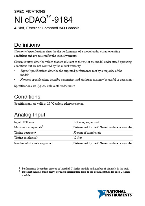
SPECIFICA TIONSNI cDAQ™-91844-Slot, Ethernet CompactDAQ ChassisDefinitionsWarranted specifications describe the performance of a model under stated operating conditions and are covered by the model warranty.Characteristics describe values that are relevant to the use of the model under stated operating conditions but are not covered by the model warranty.•Typical specifications describe the expected performance met by a majority of the models.•Nominal specifications describe parameters and attributes that may be useful in operation. Specifications are Typical unless otherwise noted.ConditionsSpecifications are valid at 25 °C unless otherwise noted.Analog InputInput FIFO size127 samples per slotMaximum sample rate1Determined by the C Series module or modules Timing accuracy250 ppm of sample rateTiming resolution212.5 nsNumber of channels supported Determined by the C Series module or modules 1Performance dependent on type of installed C Series module and number of channels in the task.2Does not include group delay. For more information, refer to the documentation for each C Series module.Analog OutputNumber of channels supportedHardware-timed taskOnboard regeneration16Non-regeneration Determined by the C Series module or modules Non-hardware-timed task Determined by the C Series module or modules Maximum update rateOnboard regeneration 1.6 MS/s (multi-channel, aggregate)Non-regeneration Determined by the C Series module or modules Timing accuracy50 ppm of sample rateTiming resolution12.5 nsOutput FIFO sizeOnboard regeneration8,191 samples shared among channels used Non-regeneration127 samples per slotAO waveform modes Non-periodic waveform,periodic waveform regeneration mode fromonboard memory,periodic waveform regeneration from hostbuffer including dynamic updateDigital Waveform CharacteristicsWaveform acquisition (DI) FIFOParallel modules511 samples per slotSerial modules63 samples per slotWaveform generation (DO) FIFOParallel modules2,047 samples per slotSerial modules63 samples per slotDigital input sample clock frequencyStreaming to application memory System-dependentFinite0 MHz to 10 MHz2| | NI cDAQ-9184 SpecificationsDigital output sample clock frequencyStreaming from application memory System-dependentRegeneration from FIFO0 MHz to 10 MHzFinite0 MHz to 10 MHzTiming accuracy50 ppmGeneral-Purpose Counters/TimersNumber of counters/timers4Resolution32 bitsCounter measurements Edge counting, pulse, semi-period, period,two-edge separation, pulse widthPosition measurements X1, X2, X4 quadrature encoding withChannel Z reloading; two-pulse encoding Output applications Pulse, pulse train with dynamic updates,frequency division, equivalent time sampling Internal base clocks80 MHz, 20 MHz, 100 kHzExternal base clock frequency0 MHz to 20 MHzBase clock accuracy50 ppmOutput frequency0 MHz to 20 MHzInputs Gate, Source, HW_Arm, Aux, A, B, Z,Up_DownRouting options for inputs Any module PFI, analog trigger, many internalsignalsFIFO Dedicated 127-sample FIFOFrequency GeneratorNumber of channels1Base clocks20 MHz, 10 MHz, 100 kHzDivisors 1 to 16 (integers)Base clock accuracy50 ppmOutput Any module PFI terminalNI cDAQ-9184 Specifications| © National Instruments| 3Module PFI CharacteristicsFunctionality Static digital input, static digital output, timinginput, and timing outputTiming output sources3Many analog input, analog output, counter,digital input, and digital output timing signals Timing input frequency0 MHz to 20 MHzTiming output frequency0 MHz to 20 MHzDigital TriggersSource Any module PFI terminalPolarity Software-selectable for most signalsAnalog input function Start Trigger, Reference Trigger,Pause Trigger, Sample Clock,Sample Clock TimebaseAnalog output function Start Trigger, Pause Trigger, Sample Clock,Sample Clock TimebaseCounter/timer function Gate, Source, HW_Arm, Aux, A, B, Z,Up_DownModule I/O StatesAt power-on Module-dependent. Refer to the documentationfor each C Series module.Network InterfaceNetwork protocols TCP/IP, UDPNetwork ports used HTTP:80 (configuration only), TCP:3580;UDP:5353 (configuration only), TCP:5353(configuration only); TCP:31415; UDP:7865(configuration only), UDP:8473 (configurationonly)Network IP configuration DHCP + Link-Local, DHCP, Static,Link-Local3Actual available signals are dependent on type of installed C Series module.4| | NI cDAQ-9184 SpecificationsHigh-performance data streams7Data stream types available Analog input, analog output, digital input,digital output, counter/timer input,counter/timer output, NI-XNET4Default MTU size1500 bytesJumbo frame support Up to 9000 bytesEthernetNetwork interface1000 Base-TX, full-duplex; 1000 Base-TX,half-duplex; 100 Base-TX, full-duplex;100 Base-TX, half-duplex; 10 Base-T,full-duplex; 10 Base-T, half-duplex Communication rates10/100/1000 Mbps, auto-negotiated Maximum cabling distance100 m/segmentPower RequirementsCaution The protection provided by the NI cDAQ-9184 chassis can be impaired ifit is used in a manner not described in the NI cDAQ-9181/9184/9188/9191 UserManual.Note Some C Series modules have additional power requirements. For moreinformation about C Series module power requirements, refer to the documentationfor each C Series module.Note Sleep mode for C Series modules is not supported in the NI cDAQ-9184.V oltage input range9 V to 30 VMaximum power consumption515 W4When a session is active, CAN or LIN (NI-XNET) C Series modules use a total of two data streams regardless of the number of NI-XNET modules in the chassis.5Includes maximum 1 W module load per slot across rated temperature and product variations.NI cDAQ-9184 Specifications| © National Instruments| 5Note The maximum power consumption specification is based on a fully populatedsystem running a high-stress application at elevated ambient temperature and withall C Series modules consuming the maximum allowed power.Power input connector 2 positions 3.5 mm pitch mini-combicon screwterminal with screw flanges, SauroCTMH020F8-0N001Power input mating connector Sauro CTF020V8, Phoenix Contact 1714977,or equivalentPhysical CharacteristicsWeight (unloaded)Approximately 643 g (22.7 oz)Dimensions (unloaded)178.1 mm × 88.1 mm × 64.3 mm(7.01 in. × 3.47 in. × 2.53 in.) Refer to thefollowing figure.Screw-terminal wiringGauge0.5 mm 2 to 2.1 mm2 (20 AWG to 14 AWG)copper conductor wireWire strip length 6 mm (0.24 in.) of insulation stripped from theendTemperature rating85 °CTorque for screw terminals0.20 N · m to 0.25 N · m (1.8 lb · in. to2.2 lb · in.)Wires per screw terminal One wire per screw terminalConnector securementSecurement type Screw flanges providedTorque for screw flanges0.20 N · m to 0.25 N · m (1.8 lb · in. to2.2 lb · in.)If you need to clean the chassis, wipe it with a dry towel.6| | NI cDAQ-9184 SpecificationsFigure 1. NI cDAQ-9184 Dimensions30.6 mm 47.2 mm Safety VoltagesConnect only voltages that are within these limits.V terminal to C terminal30 V maximum, Measurement Category IMeasurement Category I is for measurements performed on circuits not directly connected to the electrical distribution system referred to as MAINS voltage. MAINS is a hazardous liveNI cDAQ-9184 Specifications | © National Instruments | 7electrical supply system that powers equipment. This category is for measurements of voltages from specially protected secondary circuits. Such voltage measurements include signal levels, special equipment, limited-energy parts of equipment, circuits powered by regulatedlow-voltage sources, and electronics.Caution Do not connect the system to signals or use for measurements withinMeasurement Categories II, III, or IV.Note Measurement Categories CAT I and CAT O (Other) are equivalent. These testand measurement circuits are not intended for direct connection to the MAINsbuilding installations of Measurement Categories CAT II, CAT III, or CAT IV.Environmental-20 °C to 55 °C6Operating temperature (IEC 60068-2-1and IEC 60068-2-2)Caution To maintain product performance and accuracy specifications when theambient temperature is between 45 and 55 °C, you must mount the chassishorizontally to a metal panel or surface using the screw holes or the panel mount kit.Measure the ambient temperature at each side of the CompactDAQ system 63.5 mm(2.5 in.) from the side and 25.4 mm (1.0 in.) from the rear cover of the system. Forfurther information about mounting configurations, go to /info and enterthe Info Code cdaqmounting.-40 °C to 85 °CStorage temperature (IEC 60068-2-1 andIEC 60068-2-2)Ingress protection IP 30Operating humidity (IEC 60068-2-56)10% to 90% RH, noncondensingStorage humidity (IEC 60068-2-56)5% to 95% RH, noncondensingPollution Degree (IEC 60664)2Maximum altitude5,000 mIndoor use only.6When operating the NI cDAQ-9184 in temperatures below 0 °C, you must use the PS-15 powersupply or another power supply rated for below 0 °C.8| | NI cDAQ-9184 SpecificationsHazardous LocationsU.S. (UL)Class I, Division 2, Groups A, B, C, D, T4;Class I, Zone 2, AEx nA IIC T4Canada (C-UL)Class I, Division 2, Groups A, B, C, D, T4;Class I, Zone 2, Ex nA IIC T4Europe (ATEX) and International (IECEx)Ex nA IIC T4 GcShock and VibrationTo meet these specifications, you must direct mount the NI cDAQ-9184 system and affix ferrules to the ends of the terminal lines.Operational shock30 g peak, half-sine, 11 ms pulse (Tested inaccordance with IEC 60068-2-27. Test profiledeveloped in accordance withMIL-PRF-28800F.)Random vibrationOperating 5 Hz to 500 Hz, 0.3 g rmsNon-operating 5 Hz to 500 Hz, 2.4 g rms (Tested in accordancewith IEC 60068-2-64. Non-operating testprofile exceeds the requirements ofMIL PRF-28800F, Class 3.)Safety and Hazardous Locations StandardsThis product is designed to meet the requirements of the following electrical equipment safety standards for measurement, control, and laboratory use:•IEC 61010-1, EN 61010-1•UL 61010-1, CSA C22.2 No. 61010-1•EN 60079-0:2012, EN 60079-15:2010•IEC 60079-0: Ed 6, IEC 60079-15; Ed 4•UL 60079-0; Ed 6, UL 60079-15; Ed 4•CSA 60079-0:2011, CSA 60079-15:2012Note For UL and other safety certifications, refer to the product label or the OnlineProduct Certification section.NI cDAQ-9184 Specifications| © National Instruments| 9Electromagnetic CompatibilityThis product meets the requirements of the following EMC standards for electrical equipment for measurement, control, and laboratory use:•EN 61326-1 (IEC 61326-1): Class A emissions; Basic immunity•EN 55011 (CISPR 11): Group 1, Class A emissions•EN 55022 (CISPR 22): Class A emissions•EN 55024 (CISPR 24): Immunity•AS/NZS CISPR 11: Group 1, Class A emissions•AS/NZS CISPR 22: Class A emissions•FCC 47 CFR Part 15B: Class A emissions•ICES-001: Class A emissionsNote In the United States (per FCC 47 CFR), Class A equipment is intended foruse in commercial, light-industrial, and heavy-industrial locations. In Europe,Canada, Australia and New Zealand (per CISPR 11) Class A equipment is intendedfor use only in heavy-industrial locations.Note Group 1 equipment (per CISPR 11) is any industrial, scientific, or medicalequipment that does not intentionally generate radio frequency energy for thetreatment of material or inspection/analysis purposes.Note For EMC declarations and certifications, and additional information, refer tothe Online Product Certification section.CE ComplianceThis product meets the essential requirements of applicable European Directives, as follows:•2014/35/EU; Low-V oltage Directive (safety)•2014/30/EU; Electromagnetic Compatibility Directive (EMC)•2014/34/EU; Potentially Explosive Atmospheres (ATEX)Online Product CertificationRefer to the product Declaration of Conformity (DoC) for additional regulatory compliance information. To obtain product certifications and the DoC for this product, visit / certification, search by model number or product line, and click the appropriate link in the Certification column.10| | NI cDAQ-9184 SpecificationsEnvironmental ManagementNI is committed to designing and manufacturing products in an environmentally responsible manner. NI recognizes that eliminating certain hazardous substances from our products is beneficial to the environment and to NI customers.For additional environmental information, refer to the Minimize Our Environmental Impact web page at /environment. This page contains the environmental regulations and directives with which NI complies, as well as other environmental information not included in this document.Waste Electrical and Electronic Equipment (WEEE) EU Customers At the end of the product life cycle, all NI products must bedisposed of according to local laws and regulations. For more information abouthow to recycle NI products in your region, visit /environment/weee.电子信息产品污染控制管理办法(中国RoHS)中国客户National Instruments符合中国电子信息产品中限制使用某些有害物质指令(RoHS)。
国家工程器械(National Instruments)软件激活指南说明书
NOTE TO USERSActivation Instructions for National Instruments Software Your National Instruments software requires activation to access all features. Activation is simple and available 24 hours a day, 7 days a week. For more information on activation, refer to your product documentation, or visit /activate.Note If your software is a part of a V olume License Agreement (VLA) orEnterprise Agreement (EA), contact your VLA or EA administrator for installationand activation instructions.1.Install Your Software—If you install multiple products from a single piece of media, you can activate the products that you have purchased. You can install products that you have not purchased and use them in evaluation mode.Note If you already installed software that uses activation, you may not have toreinstall. Refer to the Installing and Activating Software Upgrades section in thisdocument for more information.2.Locate Your Serial Number—Your serial number uniquely identifies your purchase of NI software. You can find your serial number on the Certificate of Ownership included in your software kit. If your software kit does not include a Certificate of Ownership, you can find your serial number on the product packing slip or shipping label. For more information about finding serial numbers, visit /info and enter the Info Code SerialNumbers_en.If you have a previous version of the application installed, you can find the serial number within the application by selecting Help»About. You also can contact your local National Instruments branch. Refer to /niglobal for branch office contact information.unch the NI Licensing Wizard—The NI Licensing Wizard guides you through the activation process. If you installed your NI software for the first time, the installer may automatically launch the NI Licensing Wizard. Otherwise, launch your software and choose to activate when prompted. If you are not prompted, perform the following steps:unch NI License Manager by selecting Start»All Programs»National Instruments»NI License Manager.b.Click the Activate Software button on the ribbon.4.Save Your Activation Code for Future Use—NI Licensing Wizard sends an email confirmation of your activation code. If you reinstall your software on the same computer, you can enter the same activation code. To apply the activation code in the future, launch the NI Licensing Wizard and select Enter Activation Codes from the dialog box to enter the serial numbers.Installing and Activating Software UpgradesIf you are upgrading or moving between software packages, in most cases you do not have to install additional software, as follows:•Upgrading from an Evaluation Version to a Paid Version—If you are upgrading from an evaluation version to a paid version, you do not need to reinstall your software, even if the evaluation period has expired. Follow the prompts that appear when you launch your application or use NI License Manager to activate the software.•Moving to a Different Package of the Same Product—If you decide to move to a different product package, such as upgrading from LabVIEW Base Package to LabVIEW Professional Development System, you can activate the new package without installing additional software. Use NI License Manager to activate your software.•Activating Additional Software Packages—If you purchase add-on software, such as LabVIEW Application Builder, in some cases you do not have to install additional software to activate. Use NI License Manager to activate the software. If you do not see the software listed in NI License Manager, you need to install it.For information on how to use NI License Manager to activate software, refer to the NI License Manager Help, which you can access by clicking the blue circle icon with a question mark, located in the top right corner, or by pressing F1.Product RegistrationAt the end of activation, click the link that appears to open your browser. Follow the prompts to enter your user ID and password to register your product. NI uses the contact information that you provide to ensure access to your service benefits, including technical support, software upgrades, and updates. If you are not prompted to register, visit / support, click the Product Registration link, and manually enter your registration information.Moving Software after ActivationTo transfer your software to another computer, uninstall the software on the first computer, then install and activate it on the second computer. You are not prohibited from transferring your software from one computer to another and you do not need to contact or inform NI of the transfer. Because activation codes are unique to each computer, you will need a new activation code. Follow the steps on Page 1 of this document to acquire a new activation code and reactivate your software.2||Activation Instructions for National Instruments Software Note to UsersNI Volume License ProgramNational Instruments offers volume licenses through the NI Volume License Program and the NI Enterprise Program. These programs make managing software licenses and maintenance easy. You can use NI Volume License Manager or Flexera’s FlexNet license management tools (formerly sold as Acresso FlexNet or FLEXlm) to track your NI licenses instead of activating each copy of NI software. For more information, refer to /vlp or /ea based on the program your company chooses.Activation MethodsYou can choose among a number of activation methods using the NI Licensing Wizard, including automatic activation, online at /activate, and on the telephone. Online activation is available 24 hours a day, 7 days a week.Home Computer UseNational Instruments permits you to use most named-user and computer-based development licenses at home. To use the software, install it on your home computer and activate it using your original serial number. Refer to the NI License Manager help file, the software end-user license agreement in the installer, or /legal/license for more information. Privacy PolicyNational Instruments respects your privacy. For more information about the National Instruments activation information privacy policy, go to /activate/privacy.T ermsactivation code A 20-character code that enables NI software to run on your computer,based on your serial number and computer ID. You receive and applyan activation code by completing the activation process.computer ID A 16-character ID that uniquely identifies your computer, generatedduring the activation process. To find your computer ID, launchNI License Manager and click the Computer Information button.computer-based license A license for a single computer that allows multiple users and a single home installation.named-user license A license for a single person, limited to three installations per license, where each license is used only on one computer at a time. This license also allows a home license.serial number An alphanumeric string that uniquely identifies your purchase ofa single copy of software, included in your software kit on yourCertificate of Ownership, on the product packing slip, or on theshipping label.Activation Instructions for National Instruments Software Note to Users|© National Instruments|3National Instruments uses activation to better support evaluation of our software, to enable additional software features, and to support license management in large organizations. To find out more about National Instruments software licensing, visit /activate for frequently asked questions, resources, and technical support.Information is subject to change without notice. Refer to the NI Trademarks and Logo Guidelines at /trademarks for more information on NI trademarks. Other product and company names mentioned herein are trademarks or trade names of their respective companies. For patents covering NI products/technology, refer to the appropriate location: Help»Patents in your software, the patents.txt file on your media, or the National Instruments Patents Notice at /patents. You can find information about end-user license agreements (EULAs) and third-party legal notices in the readme file for your NI product. Refer to the Export Compliance Information at /legal/export-compliance for the NI global trade compliance policy and how to obtain relevant HTS codes, ECCNs, and other import/export data. NI MAKES NO EXPRESS OR IMPLIED WARRANTIES AS TO THE ACCURACY OF THE INFORMATION CONTAINED HEREIN AND SHALL NOT BE LIABLE FOR ANY ERRORS. U.S. Government Customers: The data contained in this manual was developed at private expense and is subject to the applicable limited rights and restricted data rights as set forth in FAR 52.227-14, DFAR 252.227-7014, and DFAR 252.227-7015.© 2003–2018 National Instruments. All rights reserved.371243M-01Oct18。
NI Academic Site License用户手册说明书
RELEASE NOTES AND INSTALLATION INSTRUCTIONS NI Academic Site LicenseNI Academic Site License provides educators, researchers, and students with a selection of National Instruments graphical system design software. Academic Site License is available as two different options:•Academic Site License: LabVIEW Option—Contains LabVIEW Professional Development System and a large set of LabVIEW modules and toolkits, alongwith other select NI software packages for extended development.•Academic Site License: Multisim Option—Contains Circuit Design Suite, featuring Multisim, Ultiboard, and Multisim Live Premium ().For a list of the software versions included in this release, refer to /info and enter the Info Code ASLsoftware.Included in your Academic Site License purchase is one year of the Standard Subscription Program (SSP) for Academic Software. This provides benefits such as the following:•Access to the latest software upgrades (/academic/download)•Ability for undergraduate students to install and activate software (/info, enter Info Code AcademicSIO)•Access to NI Online Training for students and educators at /self-paced-training•Access to technical support via email and phone from National Instruments Application Engineers (/support)For more information on SSP for Academic Software, including a complete list of benefits and list of pricing options, visit /info and enter the Info Code AcademicSSP. LabVIEW and Multisim for StudentsAn active SSP contract allows students included within the negotiated parameters of Small/ Medium/Large Academic Site License contracts to install and activate the included software on their personal computers for educational purposes. NI will deliver a new serial number each year of an active contract to distribute to students for this purpose. For more information, go to /info and enter the Info Code AcademicSIO.Software Administrator ResourcesFor information on installation, and license management resources for software distribution on your campus, refer to the Academic Site License Administrator Resources at /asl-resources.Installation and Activation InstructionsSoftware InstallationGo to /info and enter ASLsoftware to see what specific software is included in your ASL option.NI Academic Site License: LabVIEW OptionNI Academic Site License: LabVIEW Option has been grouped into a software installer suite—referred to as the NI Software Platform Bundle—which contains the majority of theNI software portfolio for building many applications in multiple environments.The NI Software Platform bundle also ships with LabVIEW NXG. Use LabVIEW NXG to quickly acquire, analyze, and present data from data acquisition devices. To determine if LabVIEW NXG meets your application needs, follow the instructions to fill out the survey that appears during the installation process.NI Software Platform Bundle InstallationThe Software Platform Bundle organization ensures that you only need to insert the media or download the installer, choose the software products you want to install, and all software will be installed in the proper order. The installer also ensures that any necessary selected driver software installs after the application software.To download the web-based Software Platform Bundle installer, go to /academic/ download and select your installer option from the LabVIEW Academic Site License Installer section. After the file downloads, double-click the file from the download location and follow the on-screen instructions.NI Academic Site License: Multisim OptionNI Academic Site License: Multisim Option has been grouped into a software installer suite—referred to as the NI Circuit Design Suite—which includes Multisim and Ultiboard software for a complete circuit design, simulation, validation, and layout platform.NI Circuit Design Suite InstallationTo install NI Circuit Design Suite, insert the media or download the installer, choose the software products you want to install, and follow any instructions on your screen.To download the web-based NI Circuit Design Suite installer, go to /academic/ download and select your installer option from the Multisim Academic Site License Installer section. After the file downloads, double-click the file from the download location and follow the on-screen instructions.2||NI Academic Site License Release Notes and Installation InstructionsSerial Numbers (Activation)Depending on which Academic Site License contract you purchased, you will receive one or more serial numbers, which are used to license and activate your National Instruments software. For assistance activating NI software, visit /activate.Software Deployment Options1.Single computer—You can install and activate software individually on a computer, butyou will need to activate the software on each computer.This is suitable for professors, researchers, and students that need to install and activate software on their laptops or lab computers.2.Multiple computers—When deploying National Instruments software to a large group ofcomputers(15or more) such as a computer lab, NI recommends using an imaging tool to automate the software installation.Before creating the image, decide if you plan to direct the image to a centralized licensing server by way of NI V olume License Manager (NI VLM) or FLEX, or if you plan to push out a computer image with an already activated license file.For more information about deploying NI software to multiple machines, visit /asl and select Software Administrator Resources.Information is subject to change without notice. Refer to the NI Trademarks and Logo Guidelines at /trademarks for more information on NI trademarks. Other product and company names mentioned herein are trademarks or trade names of their respective companies. For patents covering NI products/technology, refer to the appropriate location: Help»Patents in your software, the patents.txt file on your media, or the National Instruments Patents Notice at /patents. You can find information about end-user license agreements (EULAs) and third-party legal notices in the readme file for your NI product. Refer to the Export Compliance Information at /legal/export-compliance for the NI global trade compliance policy and how to obtain relevant HTS codes, ECCNs, and other import/export data. NI MAKES NO EXPRESS OR IMPLIED WARRANTIES AS TO THE ACCURACY OF THE INFORMATION CONTAINED HEREIN AND SHALL NOT BE LIABLE FOR ANY ERRORS. U.S. Government Customers: The data contained in this manual was developed at private expense and is subject to the applicable limited rights and restricted data rights as set forth in FAR 52.227-14, DFAR 252.227-7014, and DFAR 252.227-7015.© 2008-2019 National Instruments. All rights reserved.371738AG-01Jan19。
Lincoln Magnum PRO Curve 450 商品说明书

Operator’s ManualRegister your machine:/registerAuthorized Service and Distributor Locator: /locatorIM10416| Issue D a te Aug-17© Lincoln Global, Inc. All Rights Reserved.For use with Code Numbers:K3518-2, K3518-2-8-45, K3518-2-10-45Save for future referenceDate PurchasedCode: (ex: 10859)SECTION A:WARNINGSC ALIFORNIA PROPOSITION 65 WARNINGSWARNING: This product, when used for welding or cutting, produces fumes or gases which contain chemicals known to the State of California to cause birth defects and, in some cases, cancer. (California Health & Safety Code § 25249.5 et seq.)ARC WELDING CAN BE HAZARDOUS. PROTECTYOURSELF AND OTHERS FROM POSSIBLE SERIOUS INJURY OR DEATH. KEEP CHILDREN AWAY.PACEMAKER WEARERS SHOULD CONSULT WITH THEIR DOCTOR BEFORE OPERATING.Read and understand the following safety highlights. For additional safety information, it is strongly recommended that you purchase a copy of “Safety in Welding & Cutting - ANSI Standard Z49.1” from the American Welding Society, P.O. Box 351040, Miami, Florida 33135 or CSA Standard W117.2-1974. A Free copy of “Arc Welding Safety” booklet E205 is available from the Lincoln Electric Company, 22801 St. Clair Avenue, Cleveland, Ohio 44117-1199.BE SURE THAT ALL INSTALLATION, OPERATION,MAINTENANCE AND REPAIR PROCEDURES ARE PERFORMED ONLY BY QUALIFIED INDIVIDUALS.FOR ENGINE POWERED EQUIPMENT.1.a.Turn the engine off before troubleshootingand maintenance work unless themaintenance work requires it to be running.1.b.Operate engines in open, well-ventilated areas or vent the engineexhaust fumes outdoors. 1.c.Do not add the fuel near an open flame weldingarc or when the engine is running. Stop the engine and allow it to cool before refueling to with hot engine parts and igniting. Do not spill fuel when filling tank. If fuel is spilled, wipe it up and do not start engine until fumes have been eliminated.1.d. Keep all equipment safety guards, coversand devices in position and in good repair.Keep hands, hair, clothing and tools away from V-belts, gears, fans and all other moving parts when starting, operating or repairing equipment.1.e.In some cases it may be necessary to remove safety guards toperform required maintenance. Remove guards only when necessary and replace them when the maintenance requiring their removal is complete. Always use the greatest care when working near moving parts. 1.f. Do not put your hands near the engine fan. Do not attempt tooverride the governor or idler by pushing on the throttle control rods while the engine is running. 1.g.To prevent accidentally starting gasoline engines while turningthe engine or welding generator during maintenance work,disconnect the spark plug wires, distributor cap or magneto wire as appropriate. 1.h.To avoid scalding, do not remove the radiatorpressure cap when the engine is hot.ELECTRIC ANDMAGNETIC FIELDS MAY BE DANGEROUS2.a.Electric current flowing through any conductorcauses localized Electric and Magnetic Fields (EMF).Welding current creates EMF fields around welding cables and welding machines 2.b.EMF fields may interfere with some pacemakers, andwelders having a pacemaker should consult their physician before welding. 2.c.Exposure to EMF fields in welding may have other health effectswhich are now not known. 2.d.All welders should use the following procedures in order tominimize exposure to EMF fields from the welding circuit:2.d.1.Route the electrode and work cables together - Securethem with tape when possible.2.d.2.Never coil the electrode lead around your body.2.d.3.Do not place your body between the electrode and workcables. If the electrode cable is on your right side, the work cable should also be on your right side.2.d.4.Connect the work cable to the workpiece as close as pos-sible to the area being welded.2.d.5.Do not work next to welding power source.SAFETYTABLE OF CONTENTSTechnical Specifications.........................................................................................................................................A-1Installation ..................................................................................................................................................Section A Connector Kit Installation to Gun Cable......................................................................................................................A-2 K466-1 and K466-8 Installation (for Lincoln Feeders)................................................................................................A-3 K466-2 Installation (For Tweco Adapted Feeders)......................................................................................................A-3 K466-3 Installation (For Miller feeders; i.e. Millermatic 200, Cricket, S-32P, 54D...)...................................................A-3 K466-6 and K466-10 Installation (Wirematic and Lincoln 10 Series Feeders).............................................................A-3 Liner Installation and Trimming Instructions...............................................................................................................A-4 Rotating the Gun Tube...............................................................................................................................................A-4 Contact Tip and Gas Nozzle Installation......................................................................................................................A-4 Connection to Feeder.................................................................................................................................................A-4 Connection to Lincoln Feeders...................................................................................................................................A-4 Connection to Tweco Adapted Feeders......................................................................................................................A-4 Connection to Miller Feeders.....................................................................................................................................A-5 Connection To Lincoln Wirematic, Hobart Series 2000 Feeders, Or Sp100t Type Feeders..........................................A-5 Connection To Lincoln 10 Series Feeders..................................................................................................................A-5 Consumable Thread Sizes.........................................................................................................................................A-5Operation ..................................................................................................................................................Section B Electrodes and Equipment.........................................................................................................................................B-1 Making a Weld..........................................................................................................................................................B-1 Avoiding Wire Feeding Problems................................................................................................................................B-1Maintenance..................................................................................................................................................Section C Removal, Installation and Trimming Gun Liners.........................................................................................................C-1 Gun Tubes and Nozzles.............................................................................................................................................C-1 Gun Cables ............................................................................................................................................................C-1 Cable Repair ............................................................................................................................................................C-1 Troubleshooting............................................................................................................................................Section DPARTS CONTENT/DETAILS MAY BE CHANGED OR UPDATED WITHOUT NOTICE. FOR MOST CURRENT INSTRUCTION M ANUALS, GO TO .FIGURE 2FIGURE 3.125g)Slip the connector nut over the copper strands with the threadend out. Orient gun tube connector so machined flat is on theFIGURE 4 Pull the cut-off lead terminals off the trigger assembly andWire Feeder End Repair(REQUIRES 2 #S19492-1 TERMINALS)a)Remove the cable liner per 3.1.b)Remove the feeder end connector, molded gas plug (orbarbed fitting), cable handle nut, plastic tailpiece, andconnector cover (see Figure 6).NOTE:In order to remove the cable handle nut, the tail of the connector cover must be depressed and the cable handle nut rotated 1/4 turn counterclockwise as viewed from the feeder end.c)Remove incoming connector from cable by unscrewingconnector nut from incoming connector. If the cable innertube is difficult to remove from the connector assembly,carefully slit it lengthwise with a knife up to the brassconnector.d)Move the cable boot, cable handle, and strain relief towardthe middle of the cable past the damaged section.e)Cut off the damaged section of cable and strip off the outerjacket as shown in Figure 3. Be careful not to cut theinsulation on the control wires while stripping jacket. Stripthe red and white control leads 1/4" (6.4 mm) from the endand crimp a new S19492-1 terminal to each lead. Trim theinner tube to dimensions shown.NOTE:The cable contains four control leads. Any two control leads can be used, provided the two colors used are the same at both ends. The extra leads are spares that can be used if one of the other leads breaks.f)Check that the cable boot, cable handle and strain relief areon the cable. Slip the connector nut over the copper strands with the threaded end out. Assemble incoming connector tocable by forcing the steel tube of the connector into the inside diameter of the cable inner tube until the copper strands are butted against the incoming connector shoulder. Keeping the copper strands against the shoulder, pull the connector nutover the copper strands, engage the incoming connectorthreads, and tighten in place. Refer to Figure 4.NOTE:For best results, insert a .250" (6.4mm) diameter rod through the connector and into core of cable approximately11.00" (280 mm) when pushing the connector tube into thecable core tube. To tighten, hold the connector in place while turning the nut, then remove the rod from the core. Thisprocedure assures the inner core does not kink whileassembling or tightening.Position the plastic strain relief such that the tapered end is7.10" (180 mm) from the incoming connector (see Figure 6).Lock into place with steel housing.g)Position cable boot and cable handle on cable and assemblereplacement control wire terminals in place on the cablehandle. Insert connector cover in place. Install tailpiece and fasten to cable handle with cable handle nut. Refer to Figure 6.h)Replace the molded gas plug (or barbed fitting) and feederend connector.i)Install and trim liner per Section 1.2.FIGURE 6If for any reason you do not understand the test procedures or are unable to perform the tests/repairs safely, contact yourIf for any reason you do not understand the test procedures or are unable to perform the tests/repairs safely, contact yourATENÇÃOJapaneseChineseKoreanArabicREAD AND UNDERSTAND THE MANUFACTURER’S INSTRUCTION FOR THIS EQUIPMENT AND THE CONSUMABLES TO BE USED AND FOLLOW YOUR EMPLOYER’S SAFETY PRACTICES.SE RECOMIENDA LEER Y ENTENDER LAS INSTRUCCIONES DEL FABRICANTE PARA EL USO DE ESTE EQUIPO Y LOS CONSUMIBLES QUE VA A UTILIZAR, SIGA LAS MEDIDAS DE SEGURIDAD DE SU SUPERVISOR.LISEZ ET COMPRENEZ LES INSTRUCTIONS DU FABRICANT EN CE QUI REGARDE CET EQUIPMENT ET LES PRODUITS A ETRE EMPLOYES ET SUIVEZ LES PROCEDURES DE SECURITE DE VOTRE EMPLOYEUR.LESEN SIE UND BEFOLGEN SIE DIE BETRIEBSANLEITUNG DER ANLAGE UND DEN ELEKTRODENEINSATZ DES HER-STELLERS. DIE UNFALLVERHÜTUNGSVORSCHRIFTEN DES ARBEITGEBERS SIND EBENFALLS ZU BEACHTEN.ATENÇÃOJapaneseChineseKoreanArabicLEIA E COMPREENDA AS INSTRUÇÕES DO FABRICANTE PARA ESTE EQUIPAMENTO E AS PARTES DE USO, E SIGA AS PRÁTICAS DE SEGURANÇA DO EMPREGADOR.customer assistance policYThe business of The Lincoln Electric Company is manufacturing and selling high quality welding equipment, consumables, and cutting equipment. Our challenge is to meet the needs of our customers and to exceed their expectations. On occasion, purchasers may ask Lincoln Electric for advice or information about their use of our products. We respond to our customers based on the best information in our possession at that time. Lincoln Electric is not in a position to warrant or guarantee such advice, and assumes no liability, with respect to such information or advice. We expressly disclaim any warranty of any kind, including any warranty of fitness for any customer’s particular purpose, with respect to such information or advice. As a matter of practical consideration, we also cannot assume any respon-sibility for updating or correcting any such information or advice once it has been given, nor does the provision of information or advice create, expand or alter any warranty with respect to the sale of our products.Lincoln Electric is a responsive manufacturer, but the selection and use of specific products sold by Lincoln Electric is solely within the control of, and remains the sole responsibility of the customer. Many variables beyond the control of Lincoln Electric affect the results obtained in applying these types of fabrication methods and service requirements.Subject to Change – This information is accurate to the best of our knowledge at the time of printing. Please refer to for any updated information.。
- 1、下载文档前请自行甄别文档内容的完整性,平台不提供额外的编辑、内容补充、找答案等附加服务。
- 2、"仅部分预览"的文档,不可在线预览部分如存在完整性等问题,可反馈申请退款(可完整预览的文档不适用该条件!)。
- 3、如文档侵犯您的权益,请联系客服反馈,我们会尽快为您处理(人工客服工作时间:9:00-18:30)。
拉力: 绳或线对物体的作用力; 拉力 绳或线对物体的作用力
拉力 F
张力: 绳子内部各段之间的作 张力 用力. 用力
F
问题: 粗绳的张力(张力有分布吗 张力有分布吗?) 问题 粗绳的张力 张力有分布吗 拉紧的绳中任一截面两侧的两部分之间的 相互作用力称该截面处的张力 张力. 相互作用力称该截面处的 张力 图示为质量 均匀分布的粗绳拉重物. 均匀分布的粗绳拉重物
NIZQ
y
λyg
(2) v 恒定 a=0, 故 恒定,
F − λyg = λv 2
第17页
例题3. 一根匀质绳子, 例题 一根匀质绳子 其单位长度上的质量为λ, 盘绕在一 张光滑的水平桌面上. 以一恒定的力F竖直向上提绳 竖直向上提绳, 张光滑的水平桌面上 (3) 以一恒定的力 竖直向上提绳 当 提起高度为y时 绳端的速度v为多少 为多少? 提起高度为 时, 绳端的速度 为多少 解: (3) F − λyg = λya + λv 2 将该式变换为 将该式变换为v~y函数 函数. 函数 F 2
大学物理学 动力学基本定律
d ( mv ) 提绳过程中, 为变量 为变量. 提绳过程中 m为变量 F − λyg = dt F − λyg = λya + λv 2
依题意, 绳作匀加速直线运动, 依题意 绳作匀加速直线运动 故
m = λy
v = 2ay
2
得 : F = λ y ( 3a + g ) 得: F = λ ( v 2 + yg )
A
① ②
r
O
ϕ
C
D
B
dv dv dϕ dv dv v ∵ = ⋅ = ⋅ω = ⋅ dt dϕ dt dϕ dϕ r
n
FN
τ
dv v 由①式得 − mg sin ϕ = m ⋅ dϕ r
即 vdv = − rg sin ϕ dϕ
ϕ
mg
NIZQ
v
第15页
vdv = − rg sin ϕ dϕ
大学物理学 动力学基本定律
∫
v
0
vdv =
∫ (− rg sin ϕ )d ϕ
π − 2
ϕ
得 v = 2rg cos ϕ
v 2g cosϕ ⇒ ω= = r r
代入② 代入②式得
2
A
r
O
ϕ
C
D
B
v FN = mg cos ϕ + m = 3mg cos ϕ r
小球对圆弧的作用力为
n
FN
τ
′ FN = − FN = −3mg cos ϕ
大学物理学 动力学基本定律
11.2 km/s 7.9 km/s
万有引力定律 宇宙中的一切物体都在相互吸引着. 万有引力是自然界 宇宙中的一切物体都在相互吸引着 万有引力是自然界 的基本力之一. 的基本力之一
m m2 F = F2 = G 1 2 1 r
G = 6.6730×10⁻¹¹ N⋅m2 ⋅ kg−2
NIZQ
第11页
大学物理学 动力学基本定律
例题1. 已知: 例题 已知 F = 150 N l = 4 m a = 0 .2 m ⋅ s -2 m = 2 kg 距顶端为x米处绳中的张力 米处绳中的张力. 求: 距顶端为 米处绳中的张力 解: 对绳用牛顿第二定律
F
F − Tx − mx g = mx a (1)
m mx = x l (2)
F
mx g
a
x Tx = F − m ( g + a ) l
若绳的质量忽略,则张力等于外力 若绳的质量忽略 则张力等于外力. 则张力等于外力
x
Tx
NIZQ
第12页
大学物理学 动力学基本定律
• 摩擦力 两个物体相互接触, 两个物体相互接触 由于有相对运动或者相对运动的趋 在接触面处产生的一种阻碍物体运动的力, 摩擦力. 势, 在接触面处产生的一种阻碍物体运动的力 叫摩擦力 静摩擦力 物体没有相对运动 但有相对运动的趋势 其方 物体没有相对运动, 但有相对运动的趋势. 向总与物体相对运动的趋势相反. 向总与物体相对运动的趋势相反 最大静摩擦力
第5页
大学物理学 动力学基本定律
• 牛顿第二定律
dp d(mv) dp = F= F= F =m a dt dt dt
Fx = max Fy = may Fz = maz
1. 2. 3. 4. 5. 6. 质点动力学基本方程. 质点动力学基本方程 是合外力. 是合外力 F 加速度与合外力同向. 加速度与合外力同向 反映瞬时关系. 反映瞬时关系 适用于惯性参考系. 适用于惯性参考系 是矢量式. 是矢量式
为什么我只看到 苹果下落,未见 苹果下落 未见 地球上升呢? 地球上升呢?
NIZQ
第7页
2-1-2 力学中常见的几种力 • 万有引力 重力 牛顿的苹果传说 … … 每个人都认为月亮不往下掉 的时侯, 的时侯 只有牛顿这样的人才会 看到月亮正在往下掉. 看到月亮正在往下掉 瓦莱里, 瓦莱里 法国诗人和哲学家
NIZQ
第14页
大学物理学 动力学基本定律
例题2. 一质量为m的小球最初位于如图所示的 的小球最初位于如图所示的A点 例题 一质量为 的小球最初位于如图所示的 点, 然后沿 半径为r的光滑圆弧的内表面 的光滑圆弧的内表面ADCB下滑 试求小球在 时 下滑. 半径为 的光滑圆弧的内表面 下滑 试求小球在C时 的角速度和对圆弧表面的作用力. 的角速度和对圆弧表面的作用力 取自然坐标系, 解: 取自然坐标系 小球受力如图 dv 切向 Fτ = maτ − mg sin ϕ = m dt 2 v 法向 Fn = man FN − mg cosϕ = m r
′ FN与 n 方向相反
ϕ
mg
NIZQ
v
第16页
例题3. 一根匀质绳子, 例题 一根匀质绳子 其单位长度上的质量为λ, 盘绕在一 张光滑的水平桌面上. 张光滑的水平桌面上 (1) 设t=0时, y=0, v=0. 今以一恒定的 时 加速度a竖直向上提绳 当提起高度为y时 竖直向上提绳, 加速度 竖直向上提绳 当提起高度为 时, 作用在绳端的力 为多少? 以一恒定的速度v竖直向上提绳 竖直向上提绳, 为多少 (2) 以一恒定的速度 竖直向上提绳 当提起高度为 y时, 作用在绳端的力又是多少 时 作用在绳端的力又是多少? F 建立坐标, 解: (1) 建立坐标 受力分析如图
NIZQ
第2页
大学物理学 动力学基本定律
§2-1 牛顿定律
2-1-1 牛顿定律 1686年 ,牛顿在他的 《 自然 年 牛顿在他的 牛顿在他的《 哲学的数学原理》 哲学的数学原理 》 一书中发 表了牛顿运动三定律. 表了牛顿运动三定律
NIZQ
第3页
大学物理学 动力学基本定律
• 牛顿第一定律(惯性定律) 牛顿第一定律(惯性定律) 牛顿在他的《自然哲学的数学原理》一书中写道 牛顿在他的《自然哲学的数学原理》一书中写道: 任何物体都保持静止或匀速直线运动的状态, 任何物体都保持静止或匀速直线运动的状态 直到受到 力的作用迫使它改变这种状态为止. 力的作用迫使它改变这种状态为止 现代定义: 现代定义 自由粒子永远保持静止或匀速直线运动状态. 自由粒子永远保持静止或匀速直线运动状态 数学形式: 数学形式
质量不变时, 质量不变时
dv Fτ = maτ = m dt 2 v Fn = man = m r
NIZQ
第6页
大学物理学 动力学基本定律
• 牛顿第三定律
F = −F2 1
1. 2. 3. 4. 作用力和反作用力成对, 同时存在. 作用力和反作用力成对 同时存在 分别作用于两个物体上, 不能抵消. 分别作用于两个物体上 不能抵消 属于同一种性质的力. 属于同一种性质的力 物体静止或运动均适用. 物体静止或运动均适用
同济大学物理系 倪忠强
大学物理学 动力学基本定律
什么因素影响质点运动状态的改变? 什么因素影响质点运动状态的改变?
• 亚里士多德的观点 ——力是维持物体运动的原因。 力是维持物体运动的原因。 力是维持物体运动的原因
• 伽利略的思想实验证实 —— 维持运动状态无需力 与物体本身性质有关 与物体相互作用有关
F
o
xA xB
x
虎克定律: 在弹性限度内,弹性力的大小与弹簧的伸长量 虎克定律 在弹性限度内 弹性力的大小与弹簧的伸长量 成正比,方向指向平衡位置 方向指向平衡位置. 成正比 方向指向平衡位置
F = − kx
NIZQ
第10页
大学物理学 动力学基本定律
2. 物体间相互挤压而引起的弹性力 在弹簧的形变(伸长或压缩 较小时 在弹簧的形变 伸长或压缩)较小时 这 伸长或压缩 较小时,这 种挤压弹性力总是垂直于物体间的接触 面或接触点的公切面,故亦称法向力. 故亦称法向力 面或接触点的公切面 故亦称法向力 3. 绳子的拉力
F f = µ FN
µ称为滑动摩擦系数 通常比静摩擦系数稍小一些 计算时 称为滑动摩擦系数 通常比静摩擦系数稍小一些, 称为滑动摩擦系数, 一般可不加区别, 近似地认为µ= 一般可不加区别 近似地认为 =µ′.
NIZQ
第13页
大学物理学 动力学基本定律
2-1-3 牛顿运动定律的应用示例
在惯性参考系中, 利用牛顿运动定律, 并结合质点运动学, 在惯性参考系中 利用牛顿运动定律 并结合质点运动学 可以解决质点动力学的两类问题: 可以解决质点动力学的两类问题 1.已知作用于质点的力 或恒力或变力 求质点的运动 如 已知作用于质点的力(或恒力或变力 求质点的运动(如 已知作用于质点的力 或恒力或变力), 位置r(t)、 和加速度a(t)等 位置 、速度 v(t)和加速度 等). 和加速度 2.已知质点的运动状况 求作用于质点上的力 已知质点的运动状况, 求作用于质点上的力. 已知质点的运动状况 隔离体法(涉及到两个以上质点的运动 隔离体法 涉及到两个以上质点的运动): 涉及到两个以上质点的运动 1. 按题设要求, 有目的地选取隔离体作为研究对象. 按题设要求 有目的地选取隔离体作为研究对象 2. 选定惯性参考系 分析隔离体相对于该系的运动状况 选定惯性参考系, 分析隔离体相对于该系的运动状况. 3. 分析隔离体的受力情况 画示力图 标示出其运动情况 分析隔离体的受力情况, 画示力图, 标示出其运动情况. 4. 按牛顿第二定律列出质点方程 矢量式 按牛顿第二定律列出质点方程(矢量式 矢量式). 5. 取合适坐标轴 对上述矢量形式写出它沿各轴的分量式 取合适坐标轴, 对上述矢量形式写出它沿各轴的分量式. 6. 求解结果 必要时 应对所求得的结果进行讨论 求解结果. 必要时, 应对所求得的结果进行讨论.