LDD-N512RI-RA, 规格书,Datasheet 资料
TM512_V1.0

TM512是512差分并联协议LED驱动芯片,可选择1/2/3/4通道高精度恒流输出,并带解码转发功能,可通过DO口转换成单线归零码信号,直接控制我公司TM18系列IC,可转发192个通道数据。
TM512 解码技术精准解码DMX512信号,可兼容并拓展512协议信号,TM512对传输频率在200K~500K以内的DMX512信号完全自适应解码,无需进行任何速度设置,寻址可达4096通道。
TM512内置E2PROM,无需外接,同时支持在线写码,可通过地址写码线实现100米(点间距)*1024(TM512 级联点数)一次性在线写码。
芯片提供4个耐压24V以上的可达60毫安的高精度恒流输出通道,并且通过1个外接电阻来设定电流的输出大小。
TM512有PWM反极性降频输出功能,此功能适合外挂三极管,MOS管或大电流恒流驱动IC 的应用。
高端口刷新率,大幅提高画面刷新率。
TM512更可将多组恒流输出接口短路以扩大电流驱动能力。
它主要为建筑物装饰和舞台灯光效果LED 照明系统而设计,适合于需要并接的LED 照明系统,某一个芯片的异常完全不影响其他芯片的正常工作,维护简单方便。
本产品性能优良,质量可靠。
功能特点兼容并扩展DMX512(1990)信号协议控制方式:差分并联,最大支持4096个通道独家自适应解码技术,对信号传输速率200K~500kbps的DMX512信号可完全自适应解码内置E2PROM,无需外接E2PROM内置485接口模块,无需外加485内置485模块具有差分信号分辨率高,差分输入阻抗大的优点,可大大加强带载能力单独的地址串联写码线,可一次性自动写码,支持先安装后写码方式增强型在线级联写码方式,支持100米(点间距)*1024(TM512 级联点数)一次性在线写码 加强型写码线抗干扰设计,8项抗干扰和效验匹配设置确保不会因为写码线被干扰而误写码 E2位置外发式写码,确保IC在任何情况下(如上电掉电,电源干扰)不会对E2误写码E2地址码双备份模式,部分E2损坏也不影响地址码读取PWM控制端将256级灰度经伽码校正为1024级灰度画面刷新率2KHz以上内置5V稳压管输出耐压大于30伏特R/G/B/W 四位恒流輸出通道外置输出恒流可调电阻,每通道电流范围3~60mA±3%通道间电流差异值±3%芯片间电流差异值支持1/2/3/4组字段(slot)数据读取模式PWM 选择端可选择反极性降频功能,降频后端口刷新率为500Hz上电自检亮白灯,写码成功后亮蓝灯80nS输出通道迟滞,降低突波电流干扰工业级设计,性能稳定应用领域点光源,线条灯,洗墙灯,舞台灯光系统,室内外视频墙,装饰照明系统电平,数据位中的数据是0,则相应的时间段是低电平;数据是1,则相应的时间段是高电平。
QF1D512-DK;中文规格书,Datasheet资料

P R E L I M I N A R YQF1D512-DKSavFIRe ™ Development KitFeaturesDevelopment Tool for the QF1D512 SavFIRe chipIncludes all the Hardware and Software necessary to design, implement, and test a complete filter design Circuit board features: 1 BNC signal input connector, 1 A to D converter, 2 QF1D512 devices, USB to SPI bridge for control and data, and prototyping area with 1 BNC connector for analog I/O and four expansion connectors. Development Kit evaluation and testing capabilities:- A filter design may be evaluated by introducing an analoginput to the Development Kit board, either from a PC generated white noise source or from a user supplied source (signal generator or the actual signal of interest) - Once the analog input has been introduced, the filtereddigital output data is routed back to the PC via USB and an FFT of the data is displayed, showing the results of the filter as designed Runs under Windows®2000, XP or laterNo separate power supply or controller board is requiredDescriptionThe QF1D512-DK Development Kit is a complete hardware and software solution for the QF1D512, Simple and versatile FIR engine (SavFIRe). The kit allows the user to easily set up the configuration parameters for each of the two QF1D512 devices for the specific application and evaluate the resulting device performance.The Quickfilter software design tool allows all the necessary parameters to be generated in a quick and user-friendly manner. The userenters the desired characteristics (e.g. sampling rates, type of filter, cut-off frequencies etc.) and the software generates a configuration file for the device. The configuration files can be immediately downloaded into the QF1D512 devices on the development board, and theactual hardware performance can be monitored - either in response to a PC-generated noise source or to a user-applied signal. Device configuration parameters can be further adjusted, if necessary, until the optimum system performance is reached.Once satisfied with the performance, a configuration file can be saved for future use, for example to program devices in bulk prior to volume board manufacturing.Filter Design ScreenActual filter output from QF1D512 Rev A1, September 2006/P R E L I M I N A R YQF1D512-DKSavFIRe™ Development KitHardwareThe development board interfaces to a host PC via a USB connection. This connection supplies power to the board, although there isalso provision to supply power from an external 5 – 9V source. A bridge circuit on the board converts from the native SPI interface ofthe QF1D512 to USB. Through configuration software, the QF1D512 devices can receive input from the ADC circuit, the expansioninterface, or from data loaded from the PC. Either or both QF1D512 devices can be run on the incoming data.The analog input connects to the supplied ADC converter circuit, allowing the user to provide an analog sensor input. With theexpansion connectors and the prototyping area, alternative ADC devices, custom user circuits, and processors can be connected tothe QF1D512 devices, as well as other third party emulation platforms, allowing for full system emulation without a custom boarddesign.SoftwareThere are three main software functions provided by the included Quickfilter software:1. Filter design. A variety of different filter types can be designed and simulated, including low-pass, notched low-pass, high-pass,band-pass, dual band-pass, band-stop, and dual band-stop. Currently available filter algorithms include Parks-McLellan andWindows Sync. Desired frequencies, slope and attenuation can be input and the theoretical results observed. Completeddesigns can be saved as filter files for future use.2. Chip configuration. Various filter types can be assigned to the two QF1D512 devices available. Custom ADC interface formats,pin configurations, and averaging / decimation are programmed individually for each device. When complete, theconfigurations are downloaded to the devices on the development board. It is also possible to interrogate the various on-chipcontrol registers and save configurations for future use.3. Evaluation. Once the QF1D512 devices has been configured, analog signals can be introduced to the board, with the digitaldata routed to the devices, and the software will produce and display an FFT of the filter response. A white noise source file isprovided as a convenient method to drive the input from a PC and observe the filter characteristics.Development Kit Contents expansion• Development Board•CD containing Quickfilter software, documentation and install files.•USB cable (board to PC)•Signal cable (BNC to 3.5mm phone plug)• Quickstart GuideContact and Ordering Information: Quickfilter Technologies, Inc. Web: 1024 South Greenville Avenue, Suite 100 Email: sales@Allen, TX 75002 Phone: 214-547-0460© 2006 Quickfilter Technologies, Inc. All rights reserved. Quickfilter, the Quickfilter logo and combinations thereof, are trademarks of Quickfilter Technologies, Inc. Other product names used inthis publication are for identification purposes only and may be trademarks of their respective companies. Windows is a registered trademark of Microsoft Corp./分销商库存信息: QUICKFILTER-TECHNOLOGIES QF1D512-DK。
TP5128_Datasheet

非隔离降压型LED驱动器概述TP5128是一款专用于LED非隔离降压型恒流驱动集成电路,系统工作在谷底开关模式,转换效率高,EMI低,PF可调节至0.9,输出电流自动适应电感的感量变化和输出电压的变化,从而真正实现了恒流驱动LED。
TP5128内部集成500V功率的MOSFET,采用DIP8封装,输出高达360mA的电流,外围只需要很少的器件就可以达到优异的恒流输出。
TP5128内部集成了丰富的保护功能,包括过压保护,短路保护,逐周期电流保护,温度保护和软启动等。
TP5128采用智能热响应抑制技术,自动抑制LED灯的系统温升。
TP5128具有极低的启动电流和工作电流,可在全电压交流输入(85VAC-265VAC)范围内高效驱动LED。
管脚排列特点●内置500V功率MOSFET●无需辅助线圈供电,外围元件少●DIP8封装,输出电流可高达360mA●谷底开关,高效率,低EMI●PF 可调节至0.9●自动补偿电感的感量变化●自动适应输出电压变化●短路保护●温度保护●过压保护/开路保护●智能热响应抑制,自动抑制LED灯的系统温升●即开即亮启动技术●工作温度:- 40 ~ 100℃●封装:DIP8应用范围LED照明--非隔离降压型LED驱动器管脚描述极限参数电气参数(除非特别注明,TA=25℃)非隔离降压型LED 驱动器功能框图非隔离降压型LED 驱动器应用信息TP5128是非隔离降压型恒流驱动集成电路,内部集成高压500V 的MOSFET,采用DIP8封装,LED 电流可以输出高达360mA ,TP5128采用谷底开关模式,自适应电感感量和输出电压的变化,只需要很少的外围器件来实现恒流驱动 LED 。
芯片启动和供电TP5128工作电流小,由母线通过启动电阻直接给芯片供电。
采样电阻TP5128是一款专用于 LED非隔离降压型控制器,系统工作在谷底开关模式,只需要很少的外围器件即可实现高精度的恒流输出。
芯片逐周期的检测电感上的峰值电流,CS 端连接芯片内部,并与内部基准电压VREF 进行比较,当 CS 达到内部阈值时,系统会关掉内部功率管。
LD重要参数与特征
生产技术类培训之零件认识 -------激光二极管可调电阻的应用发光二极管(LED Light Emitting Diode)• 发光二极管是最早被用来作光纤通讯传输的光源,传输用的光源 波段主要有有780、850及1300nm等,最常用来设计为短距离(数 十至数百公尺)的数据传输如G-Ethernet、Fire-wire,作为短距通 讯主要原因除了制程简单、价格便宜外,另外是因为二极管本身 的特性,如光功率较低(约为数个μW),且光源的数值孔径较大 的关系,因此大多配合玻璃或塑料材质的多模光纤使用。
FP激光二极管(Fabry Perot Laser)• FP雷射是最早用为通讯的雷射二极管(LD laser Diode),一般常见的波 段为850、1310nm,对应的光纤可为单模或多模光纤,因其高功率 (约数个mW)、低波段线宽(Spectral width)的特性,使其可作为较长距 离的光源(一般Telecommunication约30公里左右),雷射光源与二极管 在结构上最大的不同是雷射是共振腔体的结构,简单来说,提供的 电流可使腔体内的电子因能阶的跃迁而放出光子,腔体端面可想作 是两面平行的镜子(即图三光源发出的两端面),内部折射率较空气 为高,造成光子在腔体内汇聚,当能量累积到达一定程度就会发射 出来,因此会有所谓的临界电流(Threshold)的现象。
DFB雷射(Distributed Feedback Laser)• DFB雷射是现今用作高性能的通讯光源,其结构及光电反应的特性皆 与FP雷射类似,通讯传输皆操作在临界电流之上,大部分波段在 1550nm左右,与FP的结构不同处,是DFB沿着共振腔体外部加上一层 光栅(Grating),使雷射光仅允许单一波长光源存在于腔体中,我们称为 单一纵向模态(SLM Single Longitudinal Mode),此一特性,使得产生的 功率(3~50mW)及线宽(0.8~0.08pm)方面较FP雷射更为优越,但价格也 是商品化光源中最昂贵的。
FGA25N120FTD;中文规格书,Datasheet资料

@ TC = 25oC @ TC = 100oC
Diode continuous Forward current Maximum Power Dissipation Maximum Power Dissipation Operating Junction Temperature
@ TC = 100oC @ TC = 25oC @ TC = 100oC
Symbol
Parameter
Test Conditions
VFM
Diode Forward Voltage
IF = 25A
TC = 25oC TC = 125oC
trr
Diode Reverse Recovery Time
TC = 25oC TC = 125oC
Irr
Diode Reverse Recovery Time
©2009 Fairchild Semiconductor Corporation
1
FGA25N120FTD Rev. A1
G
E
Ratings
1200 ± 25 50 25 75 25 313 125 -55 to +150 -55 to +150 300
Units
V V A A A A W W oC oC
Applications
• Induction heating and Microvewave oven • Soft switching applications
February 2009
tm
General Description
Using advanced field stop trench technology, Fairchild’s 1200V trench IGBTs offer superior conduction and switching performances, and easy parallel operation with exceptional avalanche ruggedness. This device is designed for soft switching applications.
场效应管j512参数及代换

场效应管j512参数及代换FGA25N120AND(IGBT)1200V/25A//TO3P(电磁炉用)FQA27N25(MOSFET)250V/27A/TO3P IRFP254FQA40N25(MOSFET)250V/40A/280W/0.051Ω/TO3P IRFP264FQA55N25(MOSFET)250V/55A/310W/0.03Ω/TO3PFQA18N50V2(MOSFET)500V/20A/277W/0.225ΩIRFP460AFQA24N50(MOSFET)500V/24A/290W/0.2Ω/TO3PFQA28N50(MOSFET)500V/28.4A/310W/0.126Ω/TO3P MTY30N50E FQL40N50(MOSFET)500V/40A/560W/0.085Ω/TO264 IRFPS37N50 FQA24N60(MOSFET)600V/24A/TO3PFQA10N80(MOSFET)800V/9.8A/240W/0.81Ω/TO3PFQA13N80(MOSFET)800V/13A/300W/0.Ω/TO3PFQA5N90(MOSFET)900V/5.8A/185W/2.3Ω/TO3PFQA9N90C(MOSFET)900V/8.6A/240W/1.3Ω/TO3PFQA11N90C(MOSFET)900V/11.4A/300W/0.75Ω/TO3PFFA30U20DN(快恢复二极管)200V/2×30A/40ns/TO3PDSEK60-02AFFPF30U60S(快恢复二极管)600V/30A/90ns/TO220F MUR1560 FFA30U60DN(快恢复二极管)600V/2×30A/90ns/TO3PDSEK60-06AMBRP3010NTU(肖特基)100V/30A/TO-220MBRA3045NTU(肖特基)45V/30A/TO-3PISL9R3060G2(快恢复二极管)600V/30A/35ns/200W/TO247 APT30D60BRHRG3060(快恢复二极管)600V/30A/35nS/TO247FQP44N10(MOSFET)100V/44A/146W/0.0396Ω/TO220IRF3710/IRF540NFQP70N10(MOSFET)100V/57A/160W/0.025Ω/TO220IRFP450B(MOSFET)500V/14A/0.4Ω/205W/TO3PIRFP460C(MOSFET)500V/20A/0.2~0.24Ω/235W IRFP460KA3162/FAN8800(Drive IC)单IGBT/MOSFETFET驱动ICRHRP860(快恢复二极管)600V/8A/30NS/TO-220 MUR860RHRP1560(快恢复二极管)600V/15A/TO0220 MUR1560RHRP8120(快恢复二极管)1200V/8A/75W/TO220RHRP15120(快恢复二极管)1200V/15A/TO220RHRP30120(快恢复二极管)1200V/30A/125W/TO220单DSEI20-10ARHRG30120(快恢复二极管)1200V/30A/T03PSSH45N20B(MOSFET)200V/45A/TO3P IRFP260FGL40N150D(IGBT)1500V/40A/TO264快速IGBTFGL60N100BNTD(IGBT)1000V/60A/TO264快速IGBT 1MBH60-100 HGTG10N120BND(IGBT)1200V/35A/298W/100ns/TO247HGTG11N120CND(IGBT)1200V/43A/298W/TO247HGTG18N120BND(IGBT)1200V/54A/390W/90ns/TO247FQP5N50C(MOSFET)500V/5A/73W/1.4Ω/TO-220替代:IRF830,用于35WFQPF5N50C(MOSFET)500V/5A/38W/1.4Ω/TO-220F替代:IRF830,用于35WFQP9N50C(MOSFET)500V/9A/135W/0.6Ω/TO220替代:IRF840,用于75WFQPF9N50C(MOSFET)500V/9A/44W/0.6Ω/TO-220F替代:IRF840,用于75WFQP13N50(MOSFET)500V/13.4A/190W/0.43Ω/TO220用于75W/125W产品FQPF13N50(MOSFET)500V/13.4A/48W/0.43Ω/TO220F用于75W/125W产品FQD5N50C(MOSFET)500V/5A/1.4Ω/TO252用于35WFQA16N50(MOSFET)500V/16A/200W/0.32C/TO3P用于150W到250W 的产品FDP15N50(MOSFET)500V/15A/0.43Ω/56W/TO220用于150W左右的产品FQP18N50V2(MOSFET)500V/18A/0.43Ω/208W/TO220用于250WG 到400W的产品FQPF18N50V2(MOSFET)500V/18A/0.43Ω/56W/TO220用于250WG 到400W的产品FQA18N50V2(MOSFET)500V/20A/277W/0.225Ω/TO3P用于250WG 到400W的产品FQA24N50(MOSFET)500V/24A/290W/0.2Ω/TO3P用于400W的产品FQA24N60(MOSFET)600V/23.5A/310W/0.24Ω/TO3P用于400W 的产品FQA28N50(MOSFET)500V/28.4A/310W/0.126Ω/TO3P用于400W 的产品FQL40N50(MOSFET)500V/40A/560W/0.085Ω/TO264用于560W 的产品IRF740B(MOSFET)400V/10A/0.55Ω/134W/TO220IRF730B(MOSFET)400V/5.5A/1.0Ω/73W/TO220IRF830B(MOSFET)500V/4.5A/1.5Ω/73W/TO220IRF840B(MOSFET)500V/8A/0.85Ω/134W/TO220IRFP450B(MOSFET)500V/14A/0.4Ω/205W/TO3PIRFP460C(MOSFET)500V/20A/0.2~0.24Ω/235WFQPF5N60C(MOSFET)600V/5A/TO220FFQPF8N60C(MOSFET)600V/8A/TO220FFQPF10N60C(MOSFET)600V/10A/TO220FQPF12N60(MOSFET)600V/12A/51W/0.65Ω/TO220FFCP11N60(MOSFET)650V/11A/125W0.32Ω/TO220RHRD660S(快恢复二极管)600V/6A/TO-252RHRP860(快恢复二极管)600V/8A/75W/TO-220 RHRP1560(快恢复二极管)600V/15A/TO-220单2N7002(三极管)60V/0.12A/SOT-23HUF76629D3S(MOSFET)100V/20A/110W/TO-252 HUF75639S3S(MOSFET)100V/56A/200W/TO-263ISL9V3040D3S(IGBT)430V/21A/150W/300MJ/TO252 ISL9V3040S3S(IGBT)430V/21A/150W/300MJ/TO263 ISL9V5036S3S(IGBT)360V/46A/250W/TO262FQP33N10L(MOSFET)100V/33A/52MΩ127W/TO220。
Pm25LD512C datasheet v0.7
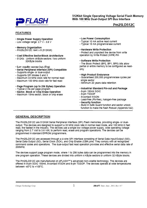
Pm25LD512CChingis Technology Corp.1DRAFT Date: June , 2011, Rev: 0.7FEATURES• Single Power Supply Operation - Low voltage range: 2.7 V - 3.6 V• Memory Organization- Pm25LD512C: 64K x 8 (512Kbit)• Cost Effective Sector/Block Architecture - 512Kb : Uniform 4KByte sectors / two uniform32KByte blocks• Low standby current 1uA (Typ)• Serial Peripheral Interface (SPI) Compatible - Supports single- or dual-output - Supports SPI Modes 0 and 3- Maximum 33 MHz clock rate for normal read - Maximum 100 MHz clock rate for fast read• Page Program (up to 256 Bytes) Operation - Typical 2 ms per page program• Sector, Block or Chip Erase Operation - Maximum 15ms sector, block or chip erase• Low Power Consumption- Typical 10 mA active read current - Typical 15 mA program/erase current• Hardware Write Protection- Protect and unprotect the device from write operation by Write Protect (WP#) Pin• Software Write Protection- The Block Protect (BP2, BP1, BP0) bits allow partial or entire memory to be configured as read-only• High Product Endurance- Guaranteed 200,000 program/erase cycles per single sector- Minimum 20 years data retention• Industrial Standard Pin-out and Package - 8-pin 150mil SOIC - 8-pin TSSOP - 8-contact WSON- Lead-free (Pb-free), halogen-free package • Security function- Build in Safe Guard function and sector unlock function to make the flash Robust (Appendix1&2)GENERAL DESCRIPTIONThe Pm25LD512C are 512Kbit Serial Peripheral Interface (SPI) Flash memories, providing single- or dual-output. The devices are designed to support a 33 MHz clock rate in normal read mode, and 100 MHz in fast read, the fastest in the industry. The devices use a single low voltage power supply, wide operating voltage ranging from 2.7 Volt to 3.6 Volt, to perform read, erase and program operations. The devices can be programmed in standard EPROM programmers.The Pm25LD512C are accessed through a 4-wire SPI Interface consisting of Serial Data Input/Output (SlO), Serial Data Output (SO), Serial Clock (SCK), and Chip Enable (CE#) pins. They comply with all recognized command codes and operations. The dual-output fast read operation provides and effective serial data rate of 200MHz.The devices support page program mode, where 1 to 256 bytes data can be programmed into the memory in one program operation. These devices are divided into uniform 4 KByte sectors or uniform 32 KByte blocks.The Pm25LD512C are manufactured on pFLASH™’s advanced non-volatile technology. The devices are offered in 8-pin SOIC 150mil, 8-contact WSON and 8-pin TSSOP. The devices operate at wide temperatures between -40°C to +105°C.512Kbit Single Operating Voltage Serial Flash Memory With 100 MHz Dual-Output SPI Bus Interface Output SPI Bus InterfacePm25LD512CChingis Technology Corp.2Date: April, 2011, Rev: 0.6PRODUCT ORDERING INFORMATIONPacking Type R = Tape & Reel Blank = TubeEnvironmental AttributeE = Lead-free (Pb-free) and Halogen- free packageTemperature RangeC = Commercial Grade (-40°C to +105°C)Package TypeS = 8-pin SOIC 150mil (8S) K = 8-contact WSON (8K) D = 8-pin TSSOP (8D)pFlash Device Number Pm25LD512CPart Number Operating Frequency (MHz) PackageTemperature RangePm25LD512C-SCE 1008S150mil SOICPm25LD512C-KCE 1008K WSON (Back Side Metal) Pm25LD512C-DCE1008D TSSOPCommercial Grade (-40o C to +105o C)Pm25LD512CChingis Technology Corp.3Date: April, 2011, Rev: 0.6CONNECTION DIAGRAMSHOLD#SCK SISO GNDWP#CE#PIN DESCRIPTIONSSYMBOL TYPE DESCRIPTIONCE#INPUT Chip Enable: CE# low activates the devices internal circuitries for device operation. CE# high deselects the devices and switches intostandby mode to reduce the power consumption. When a device is not selected, data will not be accepted via the serial input pin (Sl), and the serial output pin (SO) will remain in a high impedance state.SCK INPUT Serial Data ClockSIO INPUT/OUTPUT Serial Data Input/Output SO OUTPUTSerial Data Output GND Ground Vcc Device Power Supply WP#INPUT Write Protect: A hardware program/erase protection for all or part of amemory array. When the WP# pin is low, memory array write-protection depends on the setting of BP2, BP1 and BP0 bits in the Status Register. When the WP# is high, the devices are not write-protected.HOLD#INPUT Hold: Pause serial communication by the master device without resettingthe serial sequence.CE# SOHOLD#SCKSIOSIOVcc 8-Pin SOIC8-Contact WSON8-Pin TSSOPPm25LD512CChingis Technology Corp.4Date: April, 2011, Rev: 0.6BLOCK DIAGRAMSIOPm25LD512CChingis Technology Corp.5Date: April, 2011, Rev: 0.6SPI MODES DESCRIPTIONMultiple Pm25LD512C devices can be connected on the SPI serial bus and controlled by a SPI Master, i.e. microcontroller, as shown in Figure 1. The devices support either of two SPI modes:Mode 0 (0, 0) Mode 3 (1, 1)The difference between these two modes is the clock polarity when the SPI master is in Stand-by mode: the serial clock remains at “0” (SCK = 0) for Mode 0 and the clock remains at “1” (SCK = 1) for Mode 3. Please refer to Figure 2. For both modes, the input data is latched on the rising edge of Serial Clock (SCK), and the output data is available from the falling edge of SCK.Figure 1. Connection Diagram among SPI Master and SPI Slaves (Memory Devices)Figure 2. SPI Modes SupportedMSbMSbSCKSCKSOSIOInput mode Mode 0 (0, 0) Mode 3 (1, 1)Pm25LD512CChingis Technology Corp.6Date: April, 2011, Rev: 0.6SYSTEM CONFIGURATIONThe Pm25LD512C devices are designed to interface directly with the synchronous Serial Peripheral Interface (SPI) of the Motorola MC68HCxx series of microcontrollers or any SPI interface-equipped system controllers. The devices have two superset features that can be enabled through specific software instructions and the Configuration Register:Table 1. Block/Sector Addresses of Pm25LD512CMemory Density Block No. Block Size (KBytes) Sector No. SectorSize (KBytes)Address RangeSector 0 4 000000h - 000FFFh Sector 1 4 001000h - 001FFFh: : :Block 0 32 Sector 7 4 007000h - 007FFFh Sector 8 4 008000h - 008FFFh Sector 17 4 009000h - 009FFFh : : :512KbitBlock 1 32Sector 15 4 00F000h - 00FFFFhPm25LD512CChingis Technology Corp.7Date: April, 2011, Rev: 0.6REGISTERS (CONTINUED)STATUS REGISTERRefer to Tables 5 and 6 for Status Register Format and Status Register Bit Definitions.The BP0, BP1, BP2, and SRWD are non-volatile memory cells that can be written by a Write Status Register (WRSR) instruction. The default value of the BP2, BP1, BP0 were set to “0” and SRWD bits was set to “0” at factory. Once a “0” or “1”is written, it will not be changed by device power-up or power-down, and can only be altered by the next WRSR instruction. The Status Register can be read by the Read StatusRegister (RDSR). Refer to Table 10 for Instruction Set.The function of Status Register bits are described as follows:WIP bit : The Write In Progress (WIP) bit is read-only, and can be used to detect the progress or completion of a program or erase operation. When the WIP bit is “0”, the device is ready for a write status register, program or erase operation. When the WIP bit is “1”, the device is busy.WEL bit : The Write Enable Latch (WEL) bit indicates the status of the internal write enable latch. When the WEL is “0”, the write enable latch is disabled, and all write operations, including write status register, page program, sector erase, block and chip erase operations are inhibited. When the WEL bit is “1”, write operations are allowed. The WEL bit is set by a Write Enable (WREN) instruction. Each write register, program and erase instruction must be preceded by a WREN instruction. The WEL bit can be reset by a WriteDisable (WRDI) instruction. It will automatically be the reset after the completion of a write instruction.BP2, BP1, BP0 bits : The Block Protection (BP2, BP1, BP0) bits are used to define the portion of the memory area to be protected. Refer to Tables 7, 8 and 9 for the Block Write Protection bit settings. When a defined combination of BP2, BP1 and BP0 bits are set, the corresponding memory area is protected. Any program or erase operation to that area will be inhibited. Note: a Chip Erase (CHIP_ER) instruction is executedsuccessfully only if all the Block Protection Bits are set as “0”s.SRWD bit : The Status Register Write Disable (SRWD) bit operates in conjunction with the Write Protection (WP#) signal to provide a Hardware Protection Mode. When the SRWD is set to “0”, the Status Register is not write-protected. When the SRWD is set to “1” and the WP# is pulled low (V IL ), the volatile bits of Status Register (SRWD, BP2, BP1, BP0) become read-only, and a WRSR instruction will be ignored. If the SRWD is set to “1” and WP# is pulled high (V IH ), the Status Register can be changed by a WRSR instruction.Table 5. Status Register FormatBit 7 Bit 6 Bit 5 Bit 4 Bit 3 Bit 2 Bit 1 Bit 0 SRWD1ReservedBP2BP1 BP0 WEL WIP Default (flash bit) 0 0Pm25LD512CChingis Technology Corp.8Date: April, 2011, Rev: 0.6REGISTERS (CONTINUED)Table 6. Status Register Bit Definition BitNameDefinitionRead- /Write Non-Volatile bit Bit 0 WIP Write In Progress Bit:"0" indicates the device is ready"1" indicates a write cycle is in progress and the device is busy R No Bit 1 WEL Write Enable Latch:"0" indicates the device is not write enabled (default)"1" indicates the device is write enabledR/W No Bit 2 BP0 Bit 3 BP1 Bit 4 BP2 Block Protection Bit: (See Table 7 and Table 8 for details) "0" indicates the specific blocks are not write-protected (default) "1" indicates the specific blocks are write-protected R/W Yes Bits 5 - 6 N/A Reserved: Always "0"sN/A Bit 7 SRWD Status Register Write Disable: (See Table 9 for details)"0" indicates the Status Register is not write-protected (default)"1" indicates the Status Register is write-protectedR/WYesTable 8. Block Write Protect Bits for Pm25LD512CStatus Register Bits Protected Memory AreaBP2 BP1 BP0 512Kbit Not used 0 0 None Not used 0 1 None Not used 1 0 NoneNot used 11All blocks: 000000h - 00FFFFhPm25LD512CChingis Technology Corp.9Date: April, 2011, Rev: 0.6REGISTERS (CONTINUED)PROTECTION MODEThe Pm25LD512C have two types of write-protection mechanisms: hardware and software. These are used to prevent irrelevant operation in a possibly noisy environment and protect the data integrity.HARDWARE WRITE-PROTECTIONThe devices provide two hardware write-protection features:a. When inputting a program, erase or write status register instruction, the number of clock pulse ischecked to determine whether it is a multiple of eight before the executing. Any incomplete instruction command sequence will be ignored.b. The Write Protection (WP#) pin provides ahardware write protection method for BP2, BP1, BP0 and SRWD in the Status Register. Refer to the STATUS REGISTER description.c. Write inhibit is 2.1V, all write sequence will beignored when Vcc drop to 2.1V and lowerSOFTWARE WRITE PROTECTIONThe Pm25LD512C also provides two software write protection features:a. Before the execution of any program, erase or write status register instruction, the Write Enable Latch (WEL) bit must be enabled by executing a Write Enable (WREN) instruction. If the WEL bit is not enabled first, the program, erase or write register instruction will be ignored.b. The Block Protection (BP2, BP1, BP0) bits allow part or the whole memory area to be write-protected. Table 9. Hardware Write Protection on Status RegisterSRWD WP#Status Register 0Low Writable 1 Low Protected 0 High Writable 1HighWritablePm25LD512CChingis Technology Corp.10Date: April, 2011, Rev: 0.6DEVICE OPERATIONThe Pm25LD512C utilize an 8-bit instruction register. Refer to Table 10 Instruction Set for details of theInstructions and Instruction Codes. All instructions,addresses, and data are shifted in with the mostsignificant bit (MSB) first on Serial Data Input (SI). The input data on SI is latched on the rising edge of Serial Clock (SCK) after Chip Enable (CE#) is driven low (V IL ). Every instruction sequence starts with a one-byte instruction code and is followed by address bytes, databytes, or both address bytes and data bytes, depending on the type of instruction. CE# must be driven high (V IH ) after the last bit of the instruction sequence has been shifted in.The timing for each instruction is illustrated in the following operational descriptions.Table 10. Instruction SetInstruction NameHexCodeOperationCommand Cycle Maximum FrequencyRDIDABh Read Manufacturer and Product ID4 Bytes 100 MHz JEDEC ID READ 9Fh Read Manufacturer and Product ID by JEDEC ID Command1 Byte 100 MHz RDMDID 90h Read Manufacturer and Device ID 4 Bytes 100 MHz WREN 06h Write Enable 1 Byte 100 MHz WRDI 04h Write Disable1 Byte 100 MHz RDSR 05h Read Status Register 1 Byte 100 MHz WRSR 01h Write Status Register2 Bytes 100 MHz READ03h Read Data Bytes from Memory at Normal Read Mode 4 Bytes 33 MHz FAST_READ 0Bh Read Data Bytes from Memory at Fast Read Mode 5 Bytes 100 MHz FRDO3Bh Fast Read Dual Output5 Bytes 100 MHz PAGE_ PROG 02h Page Program Data Bytes Into Memory 4 Bytes + 256B 100 MHz SECTOR_ER D7h/20h Sector Erase 4 Bytes 100 MHz BLOCK_ER D8h Block Erase 4 Bytes 100 MHz CHIP_ERC7h/60hChip Erase1 Byte100 MHzHOLD OPERATIONHOLD# is used in conjunction with CE# to select the Pm25LD512C. When the devices are selected and a serial sequence is underway, HOLD# can be used to pause the serial communication with the master device without resetting the serial sequence.To pause, HOLD# is brought low while the SCK signal is low. To resume serial communication, HOLD# is brought high while the SCK signal is low (SCK may still toggle during HOLD). Inputs to Sl will be ignored while SO is in the high impedance state.Pm25LD512CChingis Technology Corp.11Date: April, 2011, Rev: 0.6DEVICE OPERATION (CONTINUED)RDID COMMAND (READ PRODUCT IDENTIFICATION) OPERATIONThe Read Product Identification (RDID) instruction is for reading out the old style of 8-bit Electronic Signature, whose values are shown as table of ID Definitions. This is not same as RDID or JEDEC ID instruction. It’s not recommended to use for newdesign. For new design, please use RDID or JEDEC ID instruction.The RDES instruction code is followed by three dummy bytes, each bit being latched-in on SI during the rising edge of SCK. Then the Device ID is shifted out on SO with the MSB first, each bit been shifted out during the falling edge of SCK. The RDES instruction is ended byCE# goes high. The Device ID outputs repeatedly if continuously send the additional clock cycles on SCK while CE# is at low.Table 11. Product IdentificationProduct Identification Data First Byte 9DhManufacturer ID Second Byte7Fh Device ID: Device ID 1 Device ID 2Pm25LD512C 05h 20hFigure 3. Read Product Identification SequenceSCKCE#SI SOPm25LD512CChingis Technology Corp.12Date: April, 2011, Rev: 0.6DEVICE OPERATION (CONTINUED)JEDEC ID READ COMMAND (READ PRODUCT IDENTIFICATION BY JEDEC ID) OPERATIONThe JEDEC ID READ instruction allows the user to read the manufacturer and product ID of devices. Refer to Table 11 Product Identification for pFlash Manufacturer ID and Device ID. After the JEDEC ID READ command is input, the second Manufacturer ID (7Fh) is shifted out on SO with the MSB first, followed by the first Manufacturer ID (9Dh) and the Device ID (20h), each bit shifted out during the falling edge of SCK. If CE# stays low after the last bit of the Device ID is shifted out, the Manufacturer ID and Device ID will loop until CE# is pulled high.Figure 4. Read Product Identification by JEDEC ID READ SequenceSCKCE#SISOPm25LD512CChingis Technology Corp.13Date: April, 2011, Rev: 0.6DEVICE OPERATION (CONTINUED)RDMDID COMMAND (READ DEVICE MANUFACTURER AND DEVICE ID) OPERATIONThe RDMDID instruction allows the user to read the manufacturer and product ID of devices. Refer to Table 11 Product Identification for pFlash Manufacturer ID and Device ID. The RDMDID command is input, followed by a 24-bit address pointing to an ID table. The table contains the first Manufacturer ID (9Dh) andthe Device ID (20h), and is shifted out on SO with the MSB first, each bit shifted out during the falling edge of SCK. If CE# stays low after the last bit of the Device ID is shifted out, the Manufacturer ID and Device ID will loop until CE# is pulled high.Figure 5. Read Product Identification by RDMDID READ SequencePm25LD512CChingis Technology Corp. 14 Date: April, 2011, Rev: 0.6Pm25LD512CChingis Technology Corp.15Date: April, 2011, Rev: 0.6DEVICE OPERATION (CONTINUED)WRITE ENABLE OPERATIONThe Write Enable (WREN) instruction is used to set the Write Enable Latch (WEL) bit. The WEL bit of the Pm25LD512C is reset to the write –protected state after power-up. The WEL bit must be write enabled before any write operation, including sector, block erase, chip erase, page program and write status register operations. The WEL bit will be reset to the write-protect state automatically upon completion of a write operation. The WREN instruction is required before any above operation is executed.Figure 6. Write Enable SequenceWRDI COMMAND (WRITE DISABLE) OPERATIONThe Write Disable (WRDI) instruction resets the WEL bit and disables all write instructions. The WRDI instruction is not required after the execution of a write instruction, since the WEL bit is automatically reset.Figure 7. Write Disable SequenceSIOSIOPm25LD512CChingis Technology Corp.Date: April, 2011, Rev: 0.6DEVICE OPERATION (CONTINUED)RDSR COMMAND (READ STATUS REGISTER) OPERATIONThe Read Status Register (RDSR) instruction provides access to the Status Register. During the execution of a program, erase or write status register operation, all other instructions will be ignored except the RDSR instruction, which can be used to check the progress or completion of an operation by reading the WIP bit of Status Register.Figure 8. Read Status Register SequenceWRSR COMMAND (WRITE STATUS REGISTER) OPERATIONThe Write Status Register (WRSR) instruction allows the user to enable or disable the block protection and status register write protection features by writing “0”s or “1” s into the volatile BP2, BP1, BP0 and SRWD bits.Figure 9. Write Status Register SequenceDEVICE OPERATION (CONTINUED)SIOSIOPm25LD512CChingis Technology Corp.17Date: April, 2011, Rev: 0.6READ COMMAND (READ DATA) OPERATIONThe Read Data (READ) instruction is used to read memory data of a Pm25LD512C under normal mode running up to 33 MHz.The READ instruction code is transmitted via the Sl line, followed by three address bytes (A23 - A0) of the first memory location to be read. A total of 24 address bits are shifted in, but only A MS (most significantaddress) - A0 are decoded. The remaining bits (A23 – A MS ) are ignored. The first byte addressed can be at any memory location. Upon completion, any data on the Sl will be ignored. Refer to Table 12 for the related Address Key.The first byte data (D7 - D0) addressed is then shifted out on the SO line, MSb first. A single byte of data, or up to the whole memory array, can be read out in one READ instruction. The address is automaticallyincremented after each byte of data is shifted out. The read operation can be terminated at any time by driving CE# high (V IH ) after the data comes out. When the highest address of the devices is reached, the address counter will roll over to the 000000h address, allowing the entire memory to be read in one continuous READ instruction.Table 12. Address KeyAddress Pm25LD512CA N (A MS – A 0) A15 - A0 Don't Care BitsA23 – A16Figure 12. Read Data SequenceSIOPm25LD512CChingis Technology Corp.18Date: April, 2011, Rev: 0.6DEVICE OPERATION (CONTINUED)FAST_READ COMMAND (FAST READ DATA) OPERATIONThe FAST_READ instruction is used to read memory data at up to a 100 MHz clock. The FAST_READ instruction code is followed by three address bytes (A23 - A0) and a dummy byte (8 clocks), transmitted via the SI line, with each bit latched-in during the rising edge of SCK. Then the first data byte addressed is shifted out on the SO line, with each bit shifted out at a maximum frequency f CT , during the falling edge of SCK. The first byte addressed can be at any memory location. The address is automatically incremented after each byte of data is shifted out. When the highest address is reached, the address counter will roll over to the 000000h address, allowing the entire memory to be read with a single FAST_READ instruction. The FAST_READ instruction is terminated by driving CE# high (V IH ).Figure 13. Fast Read Data SequenceSIOSIOPm25LD512CChingis Technology Corp.19Date: April, 2011, Rev: 0.6DEVICE OPERATION (CONTINUED)FRDO COMMAND (FAST READ DUAL OUTPUT) OPERATIONThe FRDO instruction is used to read memory data on two output pins each at up to a 100 MHz clock. The FRDO instruction code is followed by threeaddress bytes (A23 - A0) and a dummy byte (8 clocks), transmitted via the SI line, with each bit latched-in during the rising edge of SCK. Then the first data byte addressed is shifted out on the SO and SIO lines, with each pair of bits shifted out at a maximum frequency f CT , during the falling edge of SCK. The first bit (MSb) is output on SO, while simultaneously the second bit is output on SIO.The first byte addressed can be at any memory location. The address is automatically incremented after each byte of data is shifted out. When the highest address is reached, the address counter will roll over to the 000000h address, allowing the entire memory to be read with a single FRDO instruction. FRDO instruction is terminated by driving CE# high (V IH).Figure 14. Fast Read Dual-Output Sequence123456789101128293031...INSTRUCTION = 0011 1011b (23)22213213 - BYTE ADDRESSCE#SCKSIOSO HIGH IMPEDANCE3233343536373839404142434445464748765432107654321076CE#SCKSIOSOHIGH IMPEDANCEDATA OUT 1DATA OUT 2Pm25LD512CChingis Technology Corp.20Date: April, 2011, Rev: 0.6DEVICE OPERATION (CONTINUED)PAGE_PROG COMMAND (PAGE PROGRAM) OPERATIONThe Page Program (PAGE_PROG) instruction allows up to 256 bytes data to be programmed into memory in a single operation. The destination of the memory to be programmed must be outside the protected memoryarea set by the Block Protection (BP2, BP1, BP0) bits. A PAGE_PROG instruction which attempts to program into a page that is write-protected will be ignored.Before the execution of PAGE_PROG instruction, the Write Enable Latch (WEL) must be enabled through a Write Enable (WREN) instruction.The PAGE_PROG instruction code, three addressbytes and program data (1 to 256 bytes) are input via the Sl line. Program operation will start immediately after the CE# is brought high, otherwise thePAGE_PROG instruction will not be executed. Theinternal control logic automatically handles the programming voltages and timing. During a program operation, all instructions will be ignored except the RDSR instruction. The progress or completion of theprogram operation can be determined by reading the WIP bit in Status Register via a RDSR instruction. If the WIP bit is “1”, the program operation is still in progress. If WIP bit is “0”, the program operation hascompleted.If more than 256 bytes data are sent to a device, theaddress counter rolls over within the same page, the previously latched data are discarded, and the last 256 bytes data are kept to be programmed into the page. The starting byte can be anywhere within the page.When the end of the page is reached, the address will wrap around to the beginning of the same page. If the data to be programmed are less than a full page, the data of all other bytes on the same page will remainunchanged. Note: A program operation can alter “1”s into “0”s, but an erase operation is required to change “0”s back to “1”s. A byte cannot be reprogrammed without firsterasing the whole sector or block.Figure 15. Page Program SequenceSIOPm25LD512CChingis Technology Corp.21Date: April, 2011, Rev: 0.6DEVICE OPERATION (CONTINUED)ERASE OPERATIONThe memory array of the Pm25LD512C is organized into uniform 4 KByte sectors or 32KByte uniform blocks (a block consists of sixteen adjacent sectors).Before a byte can be reprogrammed, the sector or block that contains the byte must be erased (erasing sets bits to “1”). In order to erase the devices, there are three erase instructions available: Sector Erase(SECTOR_ER), Block Erase (BLOCK_ER) and Chip Erase (CHIP_ER). A sector erase operation allows any individual sector to be erased without affecting the data in other sectors. A block erase operation erases any individual block. A chip erase operation erases the whole memory array of a device. A sector erase, block erase or chip erase operation can be executed prior to any programming operation.SECTOR_ER COMMAND (SECTOR ERASE) OPERATIONA SECTOR_ER instruction erases a 4 KByte sector Before the execution of a SECTOR_ER instruction, the Write Enable Latch (WEL) must be set via a Write Enable (WREN) instruction. The WEL bit is reset automatically after the completion of sector an erase operation.A SECTOR_ER instruction is entered, after CE# ispulled low to select the device and stays low during the entire instruction sequence The SECTOR_ERinstruction code, and three address bytes are input via SI. Erase operation will start immediately after CE# is pulled high. The internal control logic automatically handles the erase voltage and timing. Refer to Figure 14 for Sector Erase Sequence.During an erase operation, all instruction will be ignored except the Read Status Register (RDSR) instruction. The progress or completion of the eraseoperation can be determined by reading the WIP bit in the Status Register using a RDSR instruction. If the WIP bit is “1”, the erase operation is still in progress. If the WIP bit is “0”, the erase operation has been completed.BLOCK_ER COMMAND (BLOCK ERASE) OPERATIONA Block Erase (BLOCK_ER) instruction erases a 32 KByte block of the Pm25LD512C. Before the execution of a BLOCK_ER instruction, the Write Enable Latch (WEL) must be set via a Write Enable (WREN)instruction. The WEL is reset automatically after the completion of a block erase operation.The BLOCK_ER instruction code and three address bytes are input via SI. Erase operation will startimmediately after the CE# is pulled high, otherwise the BLOCK_ER instruction will not be executed. The internal control logic automatically handles the erase voltage and timing. Refer to Figure 15 for Block Erase Sequence.CHIP_ER COMMAND (CHIP ERASE) OPERATIONA Chip Erase (CHIP_ER) instruction erases the entire memory array of a Pm25LD512C. Before the execution of CHIP_ER instruction, the Write Enable Latch (WEL) must be set via a Write Enable (WREN) instruction. The WEL is reset automatically after completion of a chip erase operation.The CHIP_ER instruction code is input via the SI. Erase operation will start immediately after CE# ispulled high, otherwise the CHIP_ER instruction will not be executed. The internal control logic automatically handles the erase voltage and timing. Refer to Figure 16 for Chip Erase Sequence.。
DMX512AP-N 应用手册
OUTR
VCC
OUTG
OUTB
限压电阻 R6/R7/R8 的取值
V IN N *V LED V DS R6/R7/R8= I LED
其中 VIN 是输入电压,也就是 12V~24V,VLED 是 LED 灯的压降,VDS 是端口电压,达到 1V 时电 流可恒定输出,ILED 是端口输出电流,可通过外接电阻 REXT 修改。比如设置输出恒流 19mA 电 流,红灯的导通压降为 2V 左右,绿和蓝灯的导通压降为 3V 左右。为了预防长距离传输的电 压衰减 VDS 至少有 1V 的电压,例如针对 24V 的应用,考虑到红灯的导通压降比较小,可通过
DMX512AP-N 应用手册 IGaBBbIAV1.1
典型时序波形图
通信数据协议 DMX512AP 数据传输采用的是标准 DMX512(1990)协议,数据传输速率是 250kbps。协议波 形如下所示:
Fig2,DMX512 协议波形
相对市场上其他的 DMX512 协议芯片,标准传输速率为 250kbps ,DMX512AP-N 支持更高 的传输速率,最大可达到 750kbps。为了提高稳定性和解码的成功率,控制器输出的 RESET 时间最好能大于 120us。
深圳市明微电子 DMX512AP-N 应用手册
1
电子邮件: market@ 网址: Tel: 0755-26991392 Fax: 0755-26991336 地址: 深圳市高新技术产业园南区高新南一道国微大厦 3 层
DMX512AP-N 应用手册 IGaBBbIAV1.1
+24V +24V
LED1 C3
LED1
LED1
LED2
LED2
LED2