OPALINUS硬泥岩热反应的监控与模拟
生烃岩热模拟实验及其结果应用
未成 熟生 油 岩较有 代 表性 。在 超过 生油 门 限后 , 随着埋 藏深 度 的增 加 , 酪根 热 降解 生 油 , 有 机 质 的氢 含 量 干 使 逐渐 变小 , 时 的生油 岩不适 于做热 模拟 实验 。 此
从 3 0 ~6 0 0℃ O ℃一 系列 瞬 时产烃 量 。 另外 把 其 中后 一 份 样 品 在热 解 炉 中 以 5 / n的 ℃ mi
生 油岩 的热解 热 模 拟 实 验 是建 立 在 干 酪根 热 降 解 生 油机 理 的基 础 上进 行 的 。 自然 界 的 有 机 质 随生 油 岩
在沉 积 盆 地 内 , 相 对 较 低 的 地 温 5 ℃ ~ 1 0 在 0 5 ℃
下 , 机质 的 自然 热 演 化 需 1 ~ 4 0 有 O 0 Ma的 时 间 , 实 在 验 室用 1 0 ~2 0 温 度 进 行 人 工 模 拟 有 机 质 热 演 8℃ 5℃ 化 也 要 几 个 月 的 时 间 ( so , 9 8 [ 。 而 用 快 速 热 Ti t 1 7 )2 s ]
4 0 、 1 ℃ 、 2 ℃ 、 3 ℃ 、 4 ℃ 、 5 ℃ 、 0 ℃ 、 5 ℃ 0 ℃ 40 40 40 40 40 50 50
上覆 沉 积物 的增加 , 度 逐 渐 升 高 , 漫长 的地 质 历 史 温 在 时期 生 成油气 。这个过 程 今天 已无 法再 现 , 在短 暂 的 要
解 的方 法在 半 小 时 内把有 机 质 加 热 至 6 0 0 ℃来 模 拟 有
经 粉碎 过 筛 ( 0 目) , 出 若 干 份 , 份 1 0 20 后 称 每 0 mg左 右 , 一 份 样 品 装 入 热 解 炉 , 5 mi 取 以  ̄ C/ n速 度 连 续 升
生烃岩热模拟实验及其结果应用
生烃岩热模拟实验及其结果应用
周丽;柳忠泉
【期刊名称】《西部探矿工程》
【年(卷),期】2011(023)009
【摘要】简要介绍热模拟实验的方法,并以鄂尔多斯盆地西缘苦深1井古生界烃源岩样品为例,开展了热模拟实验,制作出苦深1井的ⅡA型和Ⅲ型烃源岩的热演化系数关系图版和有机碳恢复系数图版,并简要叙述了图版的几点应用.同时得出,热模拟试验在恢复成熟特别是过成熟生油岩的原始面貌方面是有效的.
【总页数】5页(P45-48,51)
【作者】周丽;柳忠泉
【作者单位】胜利油田西部新区研究中心,山东东营 257015;胜利油田西部新区研究中心,山东东营 257015
【正文语种】中文
【中图分类】TE135
【相关文献】
1.山西地区太原组煤岩显微组分生烃模拟实验研究 [J], 王静;郭树芝
2.低熟页岩生烃特征的热模拟实验研究 [J], 郭少斌;毛文静;马啸
3.银根—额济纳旗盆地主力烃源岩生烃热模拟实验研究 [J], 朱连丰
4.烃源岩生烃热模拟实验方法及影响因素探讨 [J], 乔羽
5.低成熟海相黑色页岩生烃特征的热模拟实验 [J], 邓模;翟常博;杨振恒;段新国;郑伦举;宋振响
因版权原因,仅展示原文概要,查看原文内容请购买。
储能同轴深井换热器岩土热响应试验及换热性能分析

Value Engineering0引言随着低碳时代的到来,余热回收储存技术正面临新一轮的市场需求。
其中如何将火力发电厂夏季的余热储存到地下,进行冬季供暖,是值得深入研究的课题。
本文就北方某电厂计划采用同轴深井换热器进行跨季节储能,根据委托进行场地岩土热响应试验、进行数据处理分析、得出所在场区的地下岩土热物性参数,并就该技术换热性能等进行分析,为储能系统的深化设计及后期运行管理提供科学依据。
1同轴深井换热器结构简介北方某热电厂拟采用同轴深井换热器技术进行夏季余热储存和冬季取热。
先进行岩土热响应测试,获得场区岩土体岩层可钻性、初始平均温度、岩土体综合热物性及岩土体换热能力等参数。
设计DN80同轴深井1口,井深300m 。
具体结构和换热原理如下:1.1基本结构同轴深井换热器技术由我公司研发,我司编写并公开的《地源热泵同轴深井换热器应用技术导则》(Q/BHYDR001-2016),该项技术获安徽省住房和城乡建设厅鉴定(皖建科鉴字[2015]第026号)。
主要是采用钢外管及芯管组成的密闭环路形成的地下换热系统,有效深度约为300m ,内部芯管出水,外部环腔进水。
考虑管道防腐,外管非含氧层采用无缝钢管或焊管,含氧层采用镀锌钢管,含氧层套丝破坏镀锌层处采用沥青防水卷材热熔包裹,管道承压等级为1.6MPa 。
同轴深井换热器曾成功使用在某住宅小区地源热泵地埋管中[1],而由于本次同轴深井换热器用于储热。
考虑到管腔内水温要远高于地源热泵系统夏季管内循环水的温度,将原来的PE 芯管调整为耐高温的PERT 管[2],承压等级由1.0MPa 调整为1.6MPa 。
1.2换热原理循环介质经空调主机换热→地下换热器外支护套管→经充分热交换后由支护套管的底部→换热器芯管→经水平管→主机,完成换热。
外支护套管的口径远大于内管口径,在工质循环流量一定的条件下,工质在外支护套管内流速小;由于外支护套管口径、深度大,所以换热器与岩土的接触面积大,使得地下换热器与地下岩土有足够的换热空间;外支护套管内工质循环流速较小使得地下换热器有足够的时间与地下岩土进行热交换。
Cs和I在某拟建核电厂液态流出物长距离排放管线周围土壤中的扩散行为
第EU期 ! ! 陈 东 洋 等 %>)和C在 某 拟 建 核 电 厂 液 态 流 出 物 长 距 离 排 放 管 线 周 围 土 壤 中 的 扩 散 行 为
UVPX
'#*&+;#))#,-!",+60.)!%"*0"60#%&#-+#0%.,")#-./*"%+#,%0.#?**;;&6*-.,;-60&*%"!,:*" !&%-.)=T6*.,./*).",-7$,(#&#.'%-+(#,%?%#&%(#&#.',;>)i %-+CZ #-./*7",6-+:%.*"9 ),#&)').*$!./*#"+#;;6)#,-(*/%?#,")%.."%0.*+ $60/%..*-.#,-=C-./#):,"D!./*)/%&9
! 第JO卷 第EU期 !URUV年EU月
原子能科学技术 I.,$#0L-*"7'40#*-0*%-+@*0/-,&,7'
K,&=JO!A,=EU T*0=URUV
.$和E在某拟建核电厂液态流出物 距离排放管线周围土壤中的扩散行为
陈东洋EU+ 李传斌E+ 陈婧仪U杨!杰VY王建华VY 陈!媛VY王芝芬E% 吴涵玉UY% 康明亮UY
!! 我 国 核 电 厂 以 滨 海 厂 址 为 主!为 满 足 我 国 能 源 需 求 和 双 碳 目 标 等 能 源 低 碳 转 型 需 要!核 电建设将向近海厂址推进/与滨海厂址相比! 近海核电厂需要通过长距离取排水管道与受纳 水体连接!以 满 足 核 电 厂 的 用 排 水 需 求 / &E' 核 电 厂 运 行 期 间!满 足 排 放 标 准 的 放 射 性 液 态 流 出 物 通 过 输 送 管 道 进 入 受 纳 水 体!进 一 步 稀 释 和弥散/一些核电大国均建有采用长距离输送 管 道 排 放 液 态 流 出 物 的 近 海$内 陆 核 电 厂 !如 法 国EX座核电厂中有Y座 位 于 滨 海0E 座 位 于 入 海 口 !其 余 EY 座 位 于 内 陆 滨 河 *美 国 HJ 座 核 电 厂中 EH 座 位 于 滨 海$河 口0UJ 座 位 于 滨 湖0 UY座位于 滨 河 / &U' 尽 管 对 于 放 射 性 液 态 流 出 物 有 严 格 的 排 放 监 测 和 控 制!然 而 一 旦 长 距 离 输 送 管 道 发 生 破 损 !如 破 口 泄 漏 0穿 孔 持 续 泄 漏
CMG数值模拟软件简介

CMG数值模拟软件简介CMG数值模拟软件简介CMG开发的油藏数值模拟软件在市场上处于领先地位,作为提高采收率模拟的行业标准,得到了全球的认可CMG先进的模拟技术,不断开拓新领域-模拟简单到复杂的提高采收率过程。
通过结合简易的模型创建工作流程,最先进的性能增强技术以及跨学科多重机理(例如,热效应、地球化学、地质力学、流体相态、井筒、水力压裂以及完井等)精确模拟提高采收率过程。
CMOST AI强大的敏感性分析、历史拟合、方案优化以及不确定性分析工具,最大限度地提高各类油藏的采收率和净现值GEM组分模拟器世界领先的状态方程模拟器,适用于组分、化学驱以及非常规油气藏模拟IMEX黑油模拟器模拟常规和非常规油气藏模型的衰竭和二次开采过程,使用快速和简单的工作流程进行准确的预测STARS热采及化学驱模拟器准确模拟矿场提高采收率机理-热采、化学驱以及其他EOR技术-使得生产和效益最大化。
Builder前处理模块交互式、直观和易于使用的操作界面,为CMG模拟器快速和高效的准备模型Results后处理模块为更加深入的理解油藏特征、提高采收率过程以及油藏性能等提供了先进的可视化和分析工具WinProp相态模拟软件包为CMG模拟器创建流体模型,并为第三方油藏模拟软件提供黑油模型CMOST AI 提升油田开发研究能力和潜力,改善业务决策流程。
将统计分析、机器学习和无偏数据解释等人工智能技术与人类的工程专业知识相结合,确定油藏开发最佳方案。
认知油气储层在同一个模型中同时自动考虑所有不确定性参数,运行数百个模拟作业,分析数据并做出更好的业务决策。
图形展示对开发效果影响最大的参数从有限的模拟运算结果中获取信息,并通过它来认识每个参数如何影响模拟结果“假定推测”功能,快速得出属性变化对产量的影响结果,并实时更新生产曲线在更改一个或所有变量时,CMOST AI的内部引擎能自动预测变量之间的交互作用优化改进业务决策利用人工智能(AI)技术,用最少的计算找到最佳解。
塔里木盆地东部地区海相烃源岩超高温热模拟实验研究
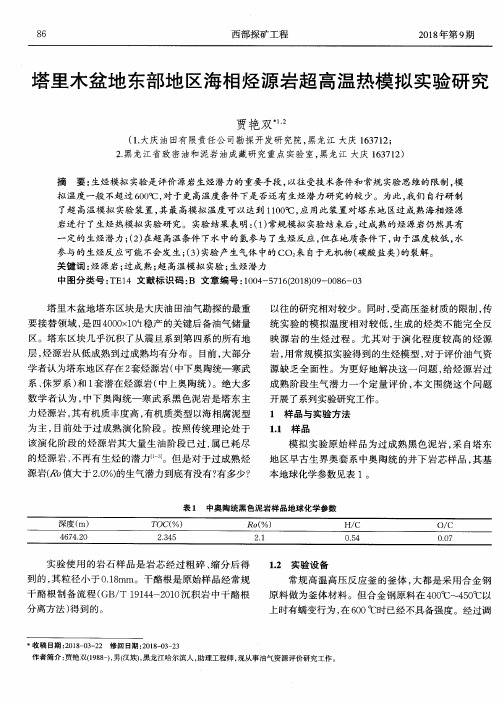
摘 要 :生 烃模拟 实验是 评 价 源岩 生烃 潜 力的 重要 手段 ,以往 受技 术条 件和 常规 实验 思维 的 限制 ,模 拟温度 一般不超过 600℃ ,对于更 高温度条件下是否还有生烃潜力研 究的较 少。为此 ,我们 自行研 制 了超 高温模 拟 实验 装置 ,其 最 高模 拟 温度 可 以达到 1IO0 ̄C,应 用此装 置 对塔 东地 区过 成 熟 海相 烃 源 岩进行 了生烃热模拟 实验研 究。实验 结果表 明:(1)常规模拟实验结束后 ,过成熟的烃源岩仍然具有 一 定的生烃潜力;(2)在超 高温条件下水中的氢参与了生烃反应 ,但在地质条件下 ,由于温度较低 ,水 参与的生烃反应可能不会发生;(3)实验产生气体 中的CO 来 自于无机物(碳酸盐类)的裂解。 关 键词 :烃 源岩 ;过成 熟 ;超 高温模 拟 实验 ;生烃 潜力 中图分 类 号 :TEl4 文献标 识 码 :B 文章 编号 :1004—5716(2018)09—0086—03
86
西 部探 矿 工程
2018年第 9期
塔 里木 盆地 东部地 区海相烃 源岩超 高温热模拟 实验研 究
贾艳 双 q
(1.大庆油 田有限责任公 司勘探开发研究院,黑龙江 大庆 163712; 2.黑龙江 省 致 密油和 泥岩 油 成藏 研 究重 点 实验 室 ,黑 龙江 大庆 163712)
模 拟 实 验 原 始 样 品为 过 成 熟 黑 色 泥 岩 ,采 自塔 东 地 区早古生界奥套 系中奥 陶统 的井下岩芯样 品 ,其基 本地 球化 学 参数 见 表 1。
表 1 中奥 陶统黑 色泥岩样品地球化学参数
实验 使 用 的 岩 石 样 品 是 岩 芯 经 过 粗 碎 、缩 分 后 得 到 的 ,其 粒 径 小 于 O.18mm。干 酪根 是 原 始样 品经 常 规 干 酪 根 制 备 流 程 (GB/T 19144—2010沉 积 岩 中 干 酪 根 分 离方 法 )得 到 的 。
冻融循环作用下泥岩的力学特性及损伤机理研究
PENG Cheng,TU Fuhao,FAN Junwei
( School of Civil Engineering, University of South China, Hengyang, Hunan 421001, China)
0 引 言
我国寒区分布广泛,永久性寒区和季节性寒 区占国土总面积的 60% 以上[1] 。 对于季节性寒 区岩土工程,由于低温导致岩体内水冰相变,如此 反复冻融过程将对岩体的物理和力学性质产生巨 大损伤,而冻融循环作用是造成寒区岩石损伤劣 化的重要因素[2] 。
国内外诸多学者对岩石的冻融损伤力学等方 面展开了相关研究。 贾海梁等[3] 研究了孔隙结 构和冻结速率对冻融损伤的控制与影响,当冻结 速率快、孔隙的渗透系数小时,则即使在连通孔隙 中,冻胀作用导致的未冻水压力仍会引起岩石的 损伤。 宋勇军[4] 研究了不同次数冻融循环条件 下单轴循环加卸载作用对红砂岩的物理力学特性 的影响;M. Krautblatte[5] 建立了岩-冰耦合力学模 型,描述 了 冻 融 损 伤 对 岩 石 边 坡 的 破 坏。 刘 哲 汛[6] 用 ABAQUS 对冻融循环后砂岩的热应力应 变以及单向受压应力应变进行了模拟。 程桦[7] 建立了毛细-薄膜水分迁移单元模型,探究了多孔 岩石在冻融循环过程中孔隙内部水分迁移导致的 冻融损伤问题。 H. Yavuz[8] 研究了冻融循环对安 山岩的单轴抗压强度以及纵波波速的影响。 史 越[9] 将横观各向同性体的柯西转轴方程和随机 损伤理论结合,建立了考虑荷载损伤状态下的层 状岩石损伤本构模型,揭示了层状岩石在单轴压 缩条件下的损伤演化机理。 宋彦琦[10] 以岩石动 态弹性模量为损伤变量建立了冻融损伤方程,研 究结果表明损伤随冻融次数增加而呈现指数衰减 型增大。 杨鸿锐[11] 通过研究砂砾岩在不同温度 区间下的冻融循环作用得到:岩石质量、波速、抗 拉强度均随冻融循环次数增加而减小,但随冻融
不同温度-应力场下泥岩蠕变特性及本构模型
长 江 科 学 院 院 报 JournalofYangtzeRiverScientificResearchInstitute
doi:10.11988/ckyyb.20170013
Vol.35 No.8 Aug.2 0 1 8
2018,35(8):84-89
1 研究背景
随着社会经济的快速发展,人类对能源的需求 不断扩大,并逐渐向深部地下工程转变,由此带来的 与温度相关的地下岩土工程问题正受到众多专家学 者的关注。流变现象是岩土工程围压失稳破坏的重 要因素之一,特别是岩石的蠕变特性,历来受到研究 工作者的高度重视[1]。在地热资源开发与利用、石 油开采、煤矿工程、高放废物处置这些长期深部地下 工程中,因为涉及到工程长期的稳定安全,岩石蠕变 行为的研究就显得更加重要,其所受应力环境往往 比较复杂,常常存在应力、温度、渗流 3场之间的耦 合作用。
速率的变化特征。
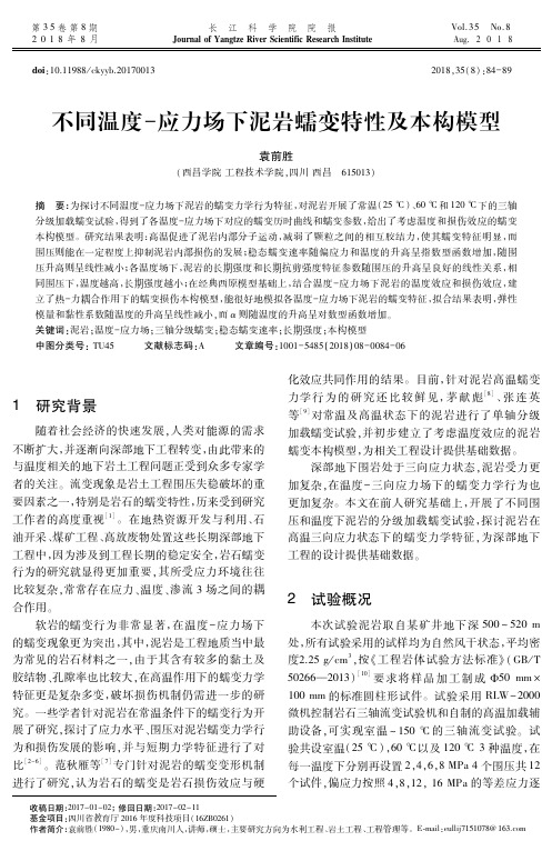
图 1 同等围压、不同温度-应力场下蠕变应变曲线 Fig.1 Curvesofcreepstraininthepresenceof differenttemperatureandstressfieldsunderthesame
confiningpressure
从图 1中可看出: (1)泥岩 在 每 一 级 加 载 后,均 会 产 生 明 显 的 瞬 时应变,之后逐渐进入稳态蠕变阶段,此时硬化效应 大于损伤效应。 (2)低加 载 应 力 状 态 下,泥 岩 的 蠕 变 特 征 并 不 显著,进入稳态蠕变阶段后蠕变变形非常缓慢。随 着应力升高,蠕变变形逐渐增大,即稳态蠕变速率逐 渐升高,在破坏应力状态下,在稳定蠕变过后,逐渐 出现非线性加速蠕变,蠕变进入非稳定型,此时损伤 效应逐渐超过硬化效应,表明泥岩进入实质性损伤, 预示着其失稳破坏即将到来。 (3)相 同 围 压 下,温 度 越 高,其 蠕 变 应 变 量 越 大,蠕变破坏应力越小,蠕变加载时间也越短,且非 线性加速蠕变特征越明显。这表明高温的软化作 用,让泥岩内部分子的热运动显著增强,一方面使得 泥岩内部颗粒力学性质发生弱化,另一方面削弱了 颗粒之间的胶结作用,因而在总体上使得泥岩的延 性得到提高,但承载力减弱,宏观上则体现为蠕变破 坏应力的降低和蠕变应变的增加 。 [11] (4)相同 温 度 下,围 压 越 大,破 坏 应 力 越 大,延 性也越强。
- 1、下载文档前请自行甄别文档内容的完整性,平台不提供额外的编辑、内容补充、找答案等附加服务。
- 2、"仅部分预览"的文档,不可在线预览部分如存在完整性等问题,可反馈申请退款(可完整预览的文档不适用该条件!)。
- 3、如文档侵犯您的权益,请联系客服反馈,我们会尽快为您处理(人工客服工作时间:9:00-18:30)。
第25卷第4期岩石力学与工程学报V ol.25 No.4 2006年4月Chinese Journal of Rock Mechanics and Engineering April,2006MONITORING AND MODELING OF RESPONSES OF THE OPALINUS CLAY TO HEATINGZHANG Chunliang1,Rothfuchs Tilmann1,Wieczorek Klaus1,Jockwer Norbert1,Wileveau Yannick2(1. Gesellschaft für Anlagen und Reaktorsicherheit(GRS),Braunschweig38122,Germany;2. Agence Nationale Pour la Gestion des Déchets Radioactifs(ANDRA),B.P.9,Bure55290,France)Abstract:In order to gain a better understanding of coupled thermo-hydro-mechanical(THM) processes in indurated clays being considered in various countries as host rock for the disposal of high-level radioactive waste,a heating experiment named HE-D is being conducted on the Opalinus clay at the Mont Terri Rock Laboratory in Switzerland. An electric heater of 5.4 m length has heated the clay rock over more than one year. The maximum temperature of 100 ℃ is reached at the heater/rock interface. During the experiment,temperature,pore water pressure,gas migration,and deformation in the clay rock have been monitored by means of more than 80 instruments installed in 24 boreholes. Thermal expansion of the heated rock was observed. In the heated region at distance about 1m to the heater,the pore water pressure increased from about 1 MPa to 4 MPa. The responses of the clay rock to heating were simulated by coupled THM modeling.Preliminary results of the field measurements and the numerical calculations are presented.Key words:nuclear waste disposal;indurated clay;field test;heating;THM processes;monitoring;modelingCLC number:TL 942+.2;TU 45 Document code:A Article ID:1000–6915(2006)04–0659–11 OPALINUS硬泥岩热反应的监控与模拟张春良1,Rothfuchs Tilmann1,Wieczorek Klaus1,Jockwer Norbert1,Wileveau Yannick 2(1. 德国核安全研究中心,德国不伦瑞克 38122;2. 法国国家放射性废物管理局,B.P.9,法国布列 55290)摘要:目前,一些国家选择硬泥岩作为核废物地质深部处置的围岩。
为深入理解硬泥岩在热–水–力(THM)耦合作用下的变化特征,在瑞士的Mont Terri地下岩石实验室对Opalinus硬泥岩进行了现场加热试验。
该试验是利用一电加热器(直径= 30 cm,长度= 5.4 m)对硬泥岩进行了1 a多的加热,然后降温0.5 a。
加热器表面的最高温度达100 ℃。
在试验过程中,安装了80多个测试传感器对硬泥岩中的温度、孔隙水压、气体渗透以及变形进行了监控。
通过观察发现围岩受热膨胀且产生明显的孔隙水压升高。
距加热器约 1 m的区域,其孔隙水压从约1 MPa 增高到4 MPa。
最后对试验中观测的硬泥岩受热所产生的热–水–力全过程进行了模拟计算,并介绍了现场测量和数值计算的初步结果。
关键词:核废物处置;硬泥岩;现场试验;加热;热–水–力过程;监测;模拟Received date:2005–08–30;Revised date:2005–12–20Corresponding author:ZHANG Chunliang(1957–),male,Ph. D.,gained his M.S. degree in Mining Engineering from Liaoning Technical University in 1984,• 660 • 岩石力学与工程学报 2006年1 INTRODUCTIONIn underground repositories ,complex coupled thermo-hydro-mechanical(THM) processes will occur in the near-field and the far-field for very long periods of time due to the excavation ,backfilling/sealing and the thermal output from high-level radioactive waste (HLW). In order to gain a better understanding of coupled THM processes in indurated clays as host rock for the disposal of HLW ,a heating experiment named HE-D is being conducted by ANDRA(France),GRS(Germany) and other partners in the Opalinus clay at the Mont Terri Rock Laboratory in Switzerland [1]. The concept of the experiment is to heat the clay formation for a long period of time in the undisturbed zone by using electric heaters. Responses of the clay rock to heating are monitored by measuring temperature ,pore water pressure ,gas migration ,and deformation in the test field. The THM processes are analyzed by numerical simulations that are performed by several teams by using different codes. To provide database for the identification of material parameters associated with the constitutive models and to examine thermal effects on the hydro-mechanical behaviour of the Opalinus clay ,various laboratory tests have also been performed at GRS ′ geotechnical laboratory [2]. The main monitoring results of the temperature ,thermally-induced pore water pressure and gas pressure as well as the numerical calculations performed by GRS are presented.2 HE-D EXPERIMENTHE-D experiment was initiated in October 2003 with excavation of the HE-D niche located in the New Gallery in the Mont Terri Rock Laboratory(Fig.1). The heater borehole BHE –D0 of 30 cm in diameter was drilled with compressed air horizontally from the HE-D niche to a depth of 14 m parallel to the bedding plane in the shaly facies of the Opalinus clay at a distance of 8 m to the MI niche(Fig. 2(a)). An electric heater equipment of 5.4 m length with two elements of 2 m length each was installed at the borehole end(Fig.2(b)). Its location is far away from the excavation disturbed zone.Four months before heating ,a series of 24 boreholes of different diameters varying between 20 and 84 mm were drilled from adjacent galleries into the near-field around the heater and equipped with more than 80 instruments to measure temperature ,pore water pressure ,gas migration and deformation before ,during and after the heating periods. The experiment was prepared with excavation of the HE-D niche ,drilling of the boreholes ,instrumentations ,and starting of the measurements within the time periodFig.1 Location of HE-D experiment in the Mont Terri Rock LaboratoryHE-D experimentMotorway tunnel50 mNSecurity galleryMicrotunnel EBNew gallery 1998Niches 1996Geological map of Mont Terri Rock LaboratoryOpalinus clay(lower alenian)S h a l y f a c i e sS h a l y f a c i e sS h a l y f a c i e sS h a l y f a c i e sS h a l yf a c i e s第25卷 第4期 ZHANG Chunliang ,et al. Monitoring and Modeling of Responses of the Opalinus Clay to Heating • 661 •(a)(b)Fig.2 Overview of HE-D experiment with the heater and measurement boreholesbetween October 2003 and March 2004. The first heating phase began in April 2004 with a total electric power of 650 Watts. The second heating phase followed at a power of 1 950 Watts until March 2005. After that ,the heater power was shut down for cooling the rock. Finally ,dismantling of the experiment is scheduled for the beginning of January 2006.3 MONITORING SYSTEMSThe particular conditions of very low permeability and free water content as well as water chemistry in argillaceous formations require adequate systems for monitoring the hydraulic behaviour such as pore water pressure and permeability. Some factors may prove to be advantageous for the design of the long-term monitoring systems [3,4]:(1) Minimization of the effective volume of thetest interval.(2) Mechanical support of the interval to prevent borehole collapse.bottom ends of the intervals to allow for a complete flushing.(4) Selection of adequate materials for the equipment to prevent corrosion.Additionally ,the borehole diameter should be as small as possible to limit the damage zone caused by the borehole drilling. The small interval volume is particularly advantageous for elimination of effects of thermal expansion of the water injected in the interval. These aspects were taken into account in the development of GRS mini-packer and multi-packer systems for the measurement of pore water pressure and gas migration in clay formations at high temperature [5].3.1 GRS mini-packer systemFig.3 shows the GRS mini-packer system for the measurement of pore water pressure and temperature in the HE-D experiment. The mini-packer is constructed of non- metallic materials and has a diameter of 20 mm and a length of 55 mm. In order to simultaneously measure the temperature ,a PT100 sensor was additionally Heater 1Heater 2BHE –D0 A z =240°,D ip = 0 φ = 302 mm L = 13.94 m 13 265 m11 765 m 10 375 m8 985 m 7 485 m 3 mTubingφ = 335 mmL = 6.50 mA ′A B ′ B C ′C D ′ D E ′EF ′F D -D ′ E -E ′Heater HE-D nicheMI niche8 mboreholeHeater borehole 8 mHE-D nicheMI niche zx• 662 • 岩石力学与工程学报 2006年(a) construction of the mini-packer (b) configuration of the boreholes in the test fieldFig.3 GRS mini-packer system for measurement of pore pressure and temperatureat a distance of 3 mm to the borehole end and fixed by mechanical strain brought about by smoothly stretching a rubber-ring of 10 mm length. The interval volume of about 1 cm3 was filled with synthetic formation water through a 1/4′′(l in = 2.54 cm)-sized inflow line. The air in the interval was displaced through the outflow line. A piezo-resistive transducer through the connecting line records the water pressure in the test interval. The system applied allows a maximum pressure of 5 MPa.A total of 11 slim boreholes of 20 mm in diameter and different lengths up to 10 m were drilled successfully from the MI niche upwards and downwards perpendicular to the heater borehole BHE–D0 and equipped with the mini-packer systems. Four boreholes BHE–D8 to D11 reached the upper area at distances of 0.9–3.0 m to heater 1,four other ones BHE–D14 to D17 reached the lower area at distances of 0.8–3.0 m to heater 2,and the rest three BHE–D7,D12 and D13 are located near the MI niche and at distances of 4.0–7.0 m to the heaters. To avoid possible leakage and collapse of the borehole,resin was injected into the remaining free space. After injecting synthetic formation water into the test intervals,the measurement was started four months before start-up of heating. It is also planned to perform gas injection tests by using this mini-packer system for determination of gas entry as well as breakthrough pressures of the rock mass after the heating phase.3.2GRS multi-packer systemFor observation of possible gas migration in the Opalinus clay during the heating period,six boreholes (BHE–D18 to D23) of 76 mm in diameter and 10 m in length were drilled from the MI niche into the upper area above heater 2. Fig.4 shows the arrangement of the boreholes with regard to the heater borehole BHE–D0. The distances of the boreholes to the heater vary between 0.8 and 1.6 m and the distances between two neighbouring boreholes are equal to 0.3 m. The boreholes were equipped with GRS multi-packer systems of 4 intervals constructed with porous ceramics. The intervals have different lengths between 50 mm and 500 mm. The sealing of the boreholes,the pressure transducers,and the data acquisition system applied are the same as those of the GRS mini-packer systems mentioned above.V≈ 1 cm3 M1 nicheHE-D Niche M1 niche第25卷 第4期 ZHANG Chunliang ,et al. Monitoring and Modeling of Responses of the Opalinus Clay to Heating • 663 •A –A sectionFig.4 GRS multi-packer system for measurement of gaspressure and migration in the test fieldAfter the installation of the instruments in the boreholes ,the packers were inflated by water to about 3.5 MPa. Two intervals BHE –D18P3 and D21P3 positioned in the mid-length of the measuring sectionwere filled with nitrogen gas at a pressure of 0.9 MPa and then shut-in ,while the other 28 intervals were not filled ,i.e. the initial gas pressure in them is atmospheric. Changes of the gas pressures in the injection and extraction intervals were monitored.4 MEASUREMENT RESULTS4.1 TemperatureFig.5 presents the evolution of the temperature recorded at some selected points in the test field before and during the heating phases. The initial temperature in the rock was measured to be about 15 ℃. The first heating with the power supply of 650 Watts generated an increase of the temperature up to 43 ℃ at the heater/rock interface over the first 3 months. The following heating with the power supply of 1 950 Watts caused a maximum temperature of 100 ℃ at the interface over other 8 months. The gradual heat transfer away from the heater resulted in a build-up of a temperature gradient. The maximum temperatures in the area at the distances of 0.8–1.4 m to the heater ranged around 23 ℃–25 ℃ during the first heating phase and 45 ℃–51 ℃ during the second heating phase ,respectively. In the far-field at distances ofFig.5 Evolution of temperature in the test field before and during the heating periodTime/dT e m p e r a t u r e /℃injectionintervalsInitial phase• 664 • 岩石力学与工程学报 2006年2.9–3.5 m to the heater ,the maximum temperatures were recorded to be 15 ℃–17 ℃ and 22 ℃–28 ℃ during both heating phases. Due to the short interruption of the power supply ,the temperature at the heater/rock interface reduced significantly ,while in the rock ,no or only slight changes of the tempera- tures were observed. From this figure ,it can also be seen that the distribution and evolution of the temperature in the test field are very well modeled(see Section 5).4.2 Pore water pressureCorrelated with the temperature increase ,the pore water pressure in the test field near the heater increased significantly. Fig.6 illustrates the evolution of the pore water pressure measured at some selected points in different distances to the heater. The initial pore water pressures were measured between 0.7 and 1.2 MPa before the drilling of the heater borehole. The subsequent borehole drilling led to a slight reduction of the pore water pressures in the near-field at distances of 0.8–1.4 m to the heater. In the far-field at a distance of 2.9 m ,no response of the pore water pressure to the drilling was observed. The first heating caused a sudden pressure increase up to 2.4 MPa in the near-field. After the stabilization of the elevated pore water pressures ,the second heating phase resulted in a rapid increase in the pore water pressure up to 4.0 MPa at points BHE –D3 and D16 at distances of 1.1–1.4 m to the heater. After reaching the maximum levels ,the pore water pressures dropped down slowly. Due to the failure of the heater packer system ,the supporting stress applied on the borehole wall was not kept. This resulted in a sharp drop of the pore water pressures at positions BHE –D14 and D15 in the weak area near the bedding plane. The re-inflation of the heater packer led to a recovery of the pressures at both points. However ,the other locations did not exhibit any response of the pore water pressure to the packer failure. Whereas the pressures in the near-field decreased gradually with flow of the thermally- mobilized pore water towards the less heated region ,the pressure at the far point BHE –D17(r = 2.90 m) rose steadily to a high level ,even higher than the pore water pressures in the more heated area. Because of the interruption of the power supply during the second heating phase ,significant responses of the pore water pressures at all the points were recorded. After a short time ,the pressures rose again to the previous levels and then reduced in the same ways as before. The gradual evolution of the pore water pressuresFig.6 Responses of the pore water pressures to heatingDateP o r e w a t e r p r e s s u r e /M P a2003–12–012004–01–312004–04–012004–06–012004–08–012004–10–012004–12–012005–01–312005–04–01Bedding (40°) BHE-D14 (0.77m)BHE-D15 (0.93m)BHE-D17 (2.91m)BHE-D16 (1.38m) BHE-D3 (1.07m)HeaterHeater BHE –D3(r = 1.07 m)BHE –D17(r = 2.91 m)BHE –D16(r = 1.38 m)BHE –D15 (r = 0.93 m) BHE –D14(r = 0.77 m) Bedding(40°) Heating1 950 W第25卷 第4期 ZHANG Chunliang ,et al. Monitoring and Modeling of Responses of the Opalinus Clay to Heating • 665 •indicates that the temperature increase to 50 ℃ did not generate any macro-fractures in the clay rock. 4.3 Gas pressureFig.7 shows the pressure recorded in test intervals BHE –D18,D19 and D20 positioned at distances of 0.8–1.1 m above heater 2. The injection interval BHE –D18 was initially filled with nitrogen gas at a pressure of 0.9 MPa and then shut-in ,while the initial gas state in the other two extraction intervals was atmospheric. Before heating ,the gas pressure in all the intervals remained constant. The first heating caused only negligible pressure increases in the intervals. However ,the second heating generated significant pressure increases. The pressures in the extraction intervals in which the initial pressures were atmospheric increased more rapidly to higher levels than the pressure in the gas-injected intervals. The gas pressure in the intervals was measured to be 1.9–2.1 MPa. The exchange of the pressure transducers of the packers in November 2004 led the packers to be unloaded to zero and re-inflated to 4.0 MPa. Correspondingly ,the pressures in all the intervals fell down shortly and rose again to the previous levels. The subsequent interruption of the power supply led also to significant changes of the pressure. Such a high pressure was not expectedfor the gas-filled and non-filled intervals. To find reasons for the high pressure ,the two extraction intervals BHE –D22P1 and D23P1 in the far-field were inspected in November 2004. Consequently ,it was observed that the intervals were filled with water. The amounts of the water collected from both intervals were 0.23 and 0.36 liters ,respectively. From this fact it can be concluded that the recorded pressures were in fact controlled by intrusion of the thermally mobilized formation water. The intruded water compressed the gas in the intervals. Because the gas and water pressure in the intervals are equal ,it was impossible for the gas to enter the saturated pores in the rock. Additionally ,the steady increase of the pressure indicates that the clay rock around the heater was not damaged due to the heating up to 100 ℃.5 MODELINGModeling work included scoping calculations for the design of the experiment and simulations for interpretation of the observed THM processes. The coupled THM calculations were performed by using CODE-BRIGHT developed by the Technical University of Catalonia in Barcelona [6],assuming the OpalinusFig.7 Measurements of gas pressure in the test intervals before and during the heating period30cm80 c mHeater 230 c mBHE -D23B HE -D21B HE -D20B HE -D18B HE -D22D19Interval ary 3r Injection intervalE xtraction interval DateG a s p r e s s u r e /M P a2004–02–01 2004–04–02 2004–06–022004–08–022004–10–022004–12–02 2005–02–01Extraction intervalBHE –D2230 cmBHE –D23BHE –D21BHE –D18Interval array 3 80 c m 20 c mBHE –D19Heater 2Heating phase 21 950 WExtraction intervalBHE –D20Injection interval• 666 • 岩石力学与工程学报 2006年clay as a homogeneous and isotropic porous medium. A set of balance equations of energy ,solid mass ,water mass ,air mass and stress equilibrium were solved. The major assumptions made are :(1) Heat transport includes conduction(Fourier ′s law) through the porous medium ,advection of liquid water and vapor flow.(2) Water transport includes two parts of liquid water advection dominated by Darcy ′s law ,vapor diffusion in air(Fick ′s law),and the liquid/gas phase changes are represented by psychrometric law.(3) Flow of dry air due to air pressure gradient (Darcy ′s law) and dissolved air in the liquid phase(Henry ′s law) are considered.(4) A thermo-elasto-plastic model was applied for the description of the mechanical behaviour of the indurated clay with the main features of thermal expansion and consolidation ,swelling and shrinking ,and so on.5.1 Prediction of HM conditionsTo ensure the heaters to be positioned in an undisturbed zone ,the hydro-mechanical processes previously developed in the potential test field were blindly predicted by the 2D coupled HM modeling ,considering the excavation and ventilation of the MI niche. Fig.8 shows the prediction of the pore water pressure distribution along the radial distance to the niche in comparison with the measurements around several drifts in the Mont Terri Rock Laboratory [3,4].Generally ,the pore water pressure in the less or undisturbed far-field is higher than in the disturbed zone. Because of the complicated geological and geohydraulic boundary conditions ,the inhomogeneity of the rock mass ,the drift excavation techniques applied and ventilation durations ,the pore pressure distribution vary in a large scatter ,very much depending on locations. From the data it is difficult to identify a clear pore water pressure distribution around a drift. The model represents more or less the mean pore water pressure distribution around the drifts. The pore water pressures measured in the HE-D test field (BHE –D03,D08–17) before heating are somewhat lower than the model. Additionally ,the negative pore water pressure calculated indicates that the surrounding rock with an extension to about 5 m might be de-saturated. Taking into account the above results and the geological conditions ,it was decided for the heater to be installed in the saturated area at a distanceFig.8 Distribution of pore water pressure around drifts in the Mont Terri Rock LaboratoryDistance from tunnel/mP o r e w a t e r p r e s s u r e /M P a第25卷 第4期 ZHANG Chunliang ,et al. Monitoring and Modeling of Responses of the Opalinus Clay to Heating • 667 •of 8 m from the MI niche.5.2 Simulation of THM processesThe observed THM processes in the clay rock during the experiment were simulated by coupled THM calculations ,considering a simple 2D axi-symmetric model for a rock mass of 25 m length and 8 m radius around the heater. The test procedure including the drilling of the heater borehole ,both heating phases ,the failure of the heater packer and the interruption of the power supply was simulated. For most of the measuring points ,the temperature ,thermally-induced over pore pressure and deformation are reasonably modeled. Some typical examples of the modeling results are shown below.Fig.9 illustrates the modeling results for point BHE –D16 at a distance of 1.4 m to the heater. It is obvious that the calculated temperature and thermally- induced pore water pressure agree well with the measurements. In addition ,the model also reveals well the responses of the temperature and the pore water pressure to the short interruption of the power supply. Fig.10 shows the distribution of the temperature and the pore water pressure around the heaters at 135 days after the second heating phase. Heating generates atemperature gradient with the maximum of about 100 ℃ at the heater surface and the ambient value of 15 ℃ in the area of 6 m far away to the heater. The thermally induced pore water over pressure concentrated in the near field around the heater.The displacements at different locations in borehole BHE –D06 drilled horizontally from the MI-niche perpendicular to the heater were measured by the project partner DBE [7] and modeled by GRS. Fig.11 presents the measured and calculated relative displacements between two points DP05 and DP03 near the heater and the temperature at point TM07 between them. Each heating generated a relative compression of the area between two measuring points for a short time and then ,the clay expanded gradually with the temperature increase. The thermal expansion resulted mainly from the pore water expansion being much higher than that of the solid grains. Generally ,the deformation induced by borehole drilling and heating is reasonably represented by the model. The mechanical model in which time-dependent deformation has not been included yet might cause the differences between the calculated and measured curves.Fig.9 Thermally-induced pore water pressure calculated and measured in the test fieldP o r e w a t e r p r e s s u r e /M P aT e m p e r a t u r e /℃Measuring pointBHE –D16 (r = 1.38 m)• 668 • 岩石力学与工程学报 2006年(a) temperature(b) pore water pressureFig.10 Distribution of temperature and thermally induced pore water pressure around the heatersFig.11 Thermally-induced deformation calculated and measured in the test field6 CONCLUSIONSIn the HE-D experiment being conducted in theOpalinus clay at the Mont Terri Rock Laboratory ,the responses of the clay rock to heating were monitored by measuring temperature ,pore water pressure ,gas migration and deformation by more than 80 instrumentsTime/dP o r e w a t e r p r e s s u r e /M P aT e m p e r a t u r e /℃第25卷第4期 ZHANG Chunliang,et al. Monitoring and Modeling of Responses of the Opalinus Clay to Heating • 669 •and modeled by coupled THM calculations. From the preliminary results,the following conclusions are drawn:(1) The mini- and multi-packer systems newly developed by GRS are suitable for the long-term observation of the hydraulic processes in clay formations of very low permeability.(2) The heating with the power supply of 650 Watts for 3 months and 1 950 Watts for 8 months generated an extension of the temperature field around the heater from the initial value of 15 ℃ to 100 ℃at the heater/rock interface and 22 ℃at a distance of 3.6 m to the heater. Correlated with the temperature increase,the pore water pressure in the test field increased from the initial values of 1.0 MPa to 4.0 MPa. The intrusion of the water into the gas testing intervals compressed the gas to high pressures up to 2.0 MPa. The gradual evolution and the high levels of the pore water pressure and gas pressure indicate that no macro-fractures were thermally generated in the clay rock during the heating phases up to 100 ℃.(3) The observed responses of the clay rock to heating are reasonably represented by the THM modeling. The evolution and distribution of the temperature,pore water pressure and deformation calculated are in good agreement with the measurements,although the model was simplified. ACKNOWLEDGEMENTS The GRS work was funded by the German Federal Ministry of Economics and Labour(BMWA) under contract 02E9773. The authors would like to thank for this support. The contributions of all the project partners to the successful conduction of the HE-D experiment are gratefully acknowledged.References(参考文献):[1] Wileveau Y,Rothfuchs T. HE-D experiment:test plan. Mont TerriProject(Technical Note,2004–20)[R]. [s. l. ]:[s. n. ],2003.[2] Zhang C L,Rothfuchs T,Su K,et al. Experimental study on thethermo-hydro-mechanical behaviour of indurated clays[A]. In:the 2ndInternational Meeting of Clays in Natural and Engineered Barriers forRadioactive Waste Confinement[C]. Tours:[s. n. ],2005. 14–18. [3] Thury M,Bossart P. Mont Terri Rock Laboratory,results of thehydrogeological,geochemical and geotechnical experiments performed in1996 and 1997[R]. Bern:Geological Berichte Nr. 23,1999.[4] Heitzmann P. Mont Terri Project—hydrogeological synthesis,osmoticflow,berichte des BWG,serie geologie,No. 6[R]. Bern:[s. n. ],2004.[5] Kull H,Jockwer N,Zhang C L,et al. Measurement of thermally-induced pore water pressure increase and gas migration in the Opalinus clay at Mont Terri[A]. In:the 2nd International Meeting ofClays in Natural and Engineered Barriers for Radioactive Waste Confinement[C]. Tours:[s. n. ],2005. 163–164.[6] UPC CODE-BRIGHT,A 3D program for thermo-hydro-mechanicalanalysis in geological media[R]. Barcelona:[s. n. ],2002.[7] Jobmann M,Polster M. The response of Opalinus clay due to heating:a combined analysis of in-situ measurements,laboratory investigationsand numerical calculations[A]. In:the 2nd International Meeting of Clays in Natural and Engineered Barriers for Radioactive Waste Confinement[C]. Tours:[s. n. ],2005. 159–160.。