SOF_CUB_MULTIHEAD_V1(0)_多振镜头控制软件使用说明
Sennheiser Multimon 监控软件用户指南说明书

Multimon SennheiserMonitoring SoftwareChat WindowThis can be opened with a button in the detail view, or by pressing the space bar. It will not open if “Attached Devices” is in use.The Send button will send the message typed above to the selected station(s) – the Alert button will do the same, and trigger a flashing alert at the other end. If the Alert button is pressed and the message field is empty, the message “Help!” will be sent.The receipt of a message will open the Chat Window and bring it to the front.The display of the touch-screen keyboard can be toggled with the “Keyboard” button.Controlling Audio Monitoring SystemsWhen a receiver is selected in the main display, if... 1 Monitor IP low byte is not zero.2 There is text in the Monitor Preamble field.3 The Monitor number in this receiver’s detail display is not zero.... a string will be broadcast over UDP to the address ending in the IP low byte value (other bytes are assumed to be the same as the transmitting computer) on port 8141. This string is:Monitor Preamble + Selected Receiver Number (2 digits) + Carriage Return/Line Feed.This string will be re-broadcast every 100ms – the audio monitoring system should acknowledge it by returning a string containing this string (minus the CrLf if required) on port 8138. At this point, the broadcast will cease, and the square around the selected receiver will change from yellow to light blue to indicated that the audio monitoring hardware has responded.Multimon in Operation on Lion King 40Ch Mixed EM 1046 & EM 3732Sennheiser Monitoring SoftwareCat. No. UKMULTIMONQuickstart Guide v 0.7.5Installation – HardwareDrivers for the USB to serial interface should be installed from the included CD. The interface can then be plugged in. The ports can be used interchangeably, but the one used for EM3532s should be set to RS-485 half-duplex, and the one used for EM1046 should be set to RS-422 full duplex. The included interface cables are labelled, and are not interchangeable.Installation – SoftwareThe software can be installed by running the installer and following the prompts.A pre-requisite is version 4.0 of the .NET runtime – the installer is included on the USB key, and is also available here:/en-gb/download/details.aspx?id=17718Main View[Single Click] s elects receiver, triggering telnet communication to any audio routing hardware, and displaying that receiver in the detail view if open. [Double Click] opens Detail view.[Shift + Click] opens Attached Devices view.[Ctrl + Click] w hen Attached Devices panel is open, changes clicked receiver display type to that selected in panel (if there is room in the display to do so). [Drag & Drop] w hen Attached Devices panel is open, moves dragged receiver in display.[Spacebar] o pens chat interface.NOTE EM3732s do not transmit RF values above 300uV.Detail ViewThe long name, short name, and notes fields are freely editable. Clicking on the silhouette allows you to associate a picture with each receiver. The monitor number sets how the receiver is identified to the monitor device.The display below shows a RF/AF history for the currently selected receiver– a receiver does not need to be selected to record history.Attached DevicesThe two drop downs allow COM ports to be selected for communicating with EM3532s and EM1046 LI. The EM1046 port should be configured as an RS-422 port, the EM3532 port as a half-duplex RS-485 port – all other settings are made by the software.The “Port for EM3532” button toggles the attached devices to display their address numbers for checking/changing. The “Port for EM1046” button does nothing.Communication with EM3732s is over LAN – the software will find all devices within the same 255.255.255.0 subnet. This assumption is also made for communication with any audio monitoring hardware, and any slave monitoring stations.When port settings are made, the scan button will attempt to find all attached devices, which will be listed in the box above. They can then be dragged on the display (multi-selection can be used), where the currently selected display type will be used. Placeholder receivers can be added to allow audio monitoring of non-Sennheiser receivers.The “System” button opens the System Dialogue.System DialogueOn start up, the system will load the file “default.xml” in My Documents/Multimon, and save current settings to this file on exit. Settings can also be loaded and saved as to other files using this dialogue.Network state allows the software to be set to master or slave – a master communicates with the receivers directly, and broadcasts this information over UDP to the subnet. If this software is set to slave on another computer on this network, it will discover and monitor these receivers automatically (they will still need to be dragged from Attached Devices on to the main view – some or all of the monitored devices can be viewed).The monitor suffix is set here – the control of monitoring hardware is discussed below.The stations chat name can be set here, as well as the timeout of the chat alert, and whether or not the touch-screen keyboard is shown by default in the chat window.。
激光振镜标刻软件说明书中文版

鑫刻激光振镜标刻软件用户使用手册软件版本:V2.0修订日期:2012年12月由于软件升级所造成的实际操作方式、功能设置等,如有与本手册不符之处,以软件为准。
目录第一章:鑫刻激光振镜标刻软件介绍 (3)1.1 软件简介 (3)1.2 软件安装 (3)1.3 软件功能 (5)1.4 软件设置 (5)1.5软件界面 (7)第二章:快速入门 (11)2.1 启动系统 (11)2.2 输入打标文件 (11)2.2.1打开旧文件 (11)2.2.2 直排文字的输入 (11)a 直排文字b. 置中c. 文字对齐方式d. 步距e. 单字属性f. 字体设置g. 填充h. 矩阵排列2.2.3 弧排文字的输入 (16)2.2.4 序列号的输入 (16)2.2.5 日期的输入 (17)2.2.6 时间的输入 (18)2.2.7 可变文本的输入 (18)2.2.8 组合替换 (19)2.2.9 数据库参数设置 (19)2.3 图形文件 (20)2.3.1 简单图形 (20)2.3.2 交互式图形 (22)a. PLT文件b. DXF文件c. AI文件d. IMG图片文件2.3.3 一维条码 (25)2.3.4 二维条码 (25)2.3.5 刻度盘 (27)2.3.6 旋转打标文件输入 (27)2.4打标参数设置 (28)2.4.1 图层参数 (28)2.4.2 延迟参数 (31)a. 跳转延时b. 开光延时c. 关光延时d. 折点延时2.5 引导红光 (33)2.5.1 定位域设置 (33)2.5.2 红光测试 (34)2.5.3 指定红光位置 (34)2.6 打标 (35)第三章:系统参数设置 (37)3.1 振镜设置 (37)3.2 辅助轴设置 (38)3.3 校正参数设置 (40)第四章:扩展功能 (42)4.1 多工位旋转打标 (42)4.2 数据库设置 (45)第五章:文件编辑示例第一章鑫刻激光振镜标刻软件介绍1.1 软件简介鑫刻软件由市鑫刻光电设计的激光振镜标刻专用软件,功能强大,简易的菜单操作方式,可打印各种中英文字体、矢量图形PLT、DXF文件、点阵图形BMP文件、序列、条形码和二维码、刻度尺。
FeiYu MG V2 3轴手持平台用户手册说明书
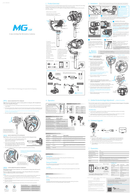
a n u a lGuiLin FeiYu Technology Incorporated Company3-Axis Gimbal for Mirrorless Camera1. Product OverviewMG V2 is one kind of 3-axis handheld gimbal especially for mirrorless cameras. Simple and clean design integrated strong operation function, easy to switch among more using ways.Panning / Tilting / Rolling 3-axis 360 degrees coverage, giving you ultimate experience while using the STEP 1Balance adjustmentof the tilting axisSTEP 2Balance adjustment of the rolling axisMount the camera on the adjustingclamping plate, fix the tilting, rolling position, and keep it at the horizon level, and turn the lens down. Observe the camera status.If the camera leans to front or back, thenloosen the motor knob ring(shown at right), and adjust the camera to the opposite position, until the camera can mount properlyadapter should be live B2 direction.B2 direction.adjustment (shown at right).gravity in vertical position.Adjust the center of gravity of the camera ’s horizon position in rolling axis, after the adjustment of the center of gravity in tilting axis.and the lens retaining ring.Fix rolling position manually and keep the camera at the horizon level, leave hold of it and observe the camera status.If the camera leans to left or rihgt, then loosen the motor knob ring (shown at bellow), and adjust the crossarm to the opposite position of the cross arm, until the camera keep the current position after adjustment.(1)Adjust the center of gravity of the camera’s vertical position in tilting axis(2)a.b.c.a.b.c.a.b.Keep the socket connector of the gimbal parallel to theground, refer the right picture:leave hold of it and observe the camera status.a.b.If the camera leaning left or right, loosen the Motorknob ring (shown at bellow), adjust the vertical arm to leaning opposite direction,until the camera keep the current position after adjustment.HorizontalPackage ListBlue light keeps flashing Initialization failure / MalfunctionLow battery (please charge or change the batteries)Red light flashes three times Red light keeps flashingEntering standby / Entering power offReset the tilting axis of the gimbal to initial orientation and initial modeOperationDouble tapSingle tap FunctionExplanationPanning mode / Lock mode Panning and Tilting mode Triple tap Under panning and tilting mode, single tap to switch to lock modeRotate 180°in horizontal Make the camera lens rotate 180 °Single tap to switch between panning mode and lock mode Quadruple tapReset Single tap again to awake the gimbal, or triple tap to initialize the gimbalLong press for 1 secondStandby Long press for 3 secondsPower offOperating Instructions of Function ButtonWorking ModesOther FunctionsPanning ModeThe camera can move to left or right smoothly along with the handheld moving. The tilting and rolling directions fixed. * Boot default mode: Panning modePanning and Tilting ModeThe camera can move to left or right and tilt up and down smoothly along with the handheldmoving. The rolling directions fixed.Lock ModeThe camera stays in its current orientation. The panning, tilting and rolling direction are all fixed.ResetReset the tilting axis of the gimbal to initial orientation and initial mode.StandbyIn standby model, keep the gimbal in power-up state, the motor stops working, the indicator light flashes for three times, and single tap again to wake the gimbal.(1)(2)(3)When the initialization failed, the LED indicator will flash quickly, repeat step (2) to reinitialize.7. Parameters887g (Not including the accessories of batteries,camera,camera lens and ect.)Panning Increments3°/s ~ 150°/sAdaption WeightSony NEX-5N/NEX-7 and other N-series, SONY A7RII / ILCE-7R / ILCE-5100, Panasonic LUMIX GH4, Canon 5D Mark III (with standard lens), and other cameras with similar dimensions with weight less 1630g (The camera weight including the accessories of lens and ect.)Usage Time 6 HoursTilting Increments 2°/s ~ 75°/s Tilting / Rolling / Panning 360°(1)(2) Lay the gimbal on a static flat surface and triple tap the Function Botton. Initialization is successfulwhen the blue light changes from constant on to flashing 3 times periodically.(1)Connect the USB cable with micro port as the above picture.(2)(3)Please visit the official website to download the relevant programs forupgrading, including USB drive program, firmware upgrade software and product firmware, and install the relevant software, decompress the firmware files for standby application.Please upgrade the relevant firmware according to the operation instructions of firmwareupgrade software.As shown, if the camera is tilted toward A1, move the cross arm to A2 direction, if tilted toward B1, Adjusting steps:Decrease the parameterIncrease the parameter(1)(2)(3)(4)After power on, You can adjust the adaptation parameter of the corresponding axis while operation thefunction corresponding keys (as shown below).the led will keep flashing in the adjust mode.If the panning axis / rolling roll / tilting axis from side to side, then move up the joystick to increase the adaptation parameter.If the motor has felt the feeling of holding the handle, then move down the joystick to decrease theadaptation parameter.If there is a slight vibration happen on the panning / rolling / tilting axis after power on the gimbal, it means the adaptation parameters needs to be adjusted.Steps:。
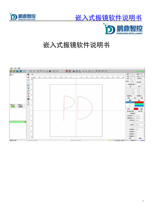
嵌入式振镜软件说明书
嵌入式振镜软件说明书版权申明深圳市鹏鼎智控科技有限公司保留所有权利深圳市鹏鼎智控科技有限公司保留在不事先通知的情况下,修改本手册中的产品和产品规格等文件的权力。
我司不承担由于使用本手册或本产品不当,所造成直接的、间接的、特殊的、附带的或相应产生的损失或责任。
我司具有本产品及其软件的专利权、版权和其它知识产权。
未经授权,不得直接或者间接地复制、制造、加工、使用本产品及其相关部分。
联系我们深圳市鹏鼎智控科技有限公司地址:深圳市光明区公明街道东周社区康佳科技中心A12层H12网址:/1.简介1.1版本说明版本号更新说明软件版本号更新人更新时间V1.0初版 1.0.0蔡恩宏2022/04/091.2振镜控制卡支持卡型号支持或特性图例PDU5000-YLR-通用IO输入×20A1通用IO输出×18HDMI接口×1网口接口×1USB接口×4IO24V供电振镜分光3路扩展轴直插扩展轴限位×6板卡15V供电激光器直插振镜直插PDU5000-YA通用IO输入×20G-V6K2通用IO输入×18HDMI接口×1网口接口×1USB接口×4IO24V供电振镜分光3路扩展轴直插扩展轴限位×6板卡15V供电激光器波形IO振镜直插1.3安装说明板卡配件:10pin端子*4(YAG卡多一个),3pin端子*2,6pin端子*1,振镜线*1(按需供应),振镜*1(按需供应),场镜*1(按需供应)自备:DB25公头*,DB25母头*1(YAG卡不需要),DB15端公头*1,DB9母头*1,DB9公头*1(YAG卡不需要)鼠标*1,键盘*1,HDMI显示屏*1(注意:若显示屏接口为VAG,则需要加一个VAG转HDMI转换器,显示屏不能太差!)安装:在其他硬件确保安装正确的情况下,先把振镜线接到板卡上J3,即DB25振镜接口上,接着接激光器线(YLR 插J7的DB25母头,YAG接波形IO线),然后接上显示屏的HDMI,显示屏上电,然后上15V电源供电,有IO接IO,IO单独供24V电源,打开整机电源开关,等启动之后,就直接进入软件界面,检查软件右上角,无特殊情况,卡肯定会打开成功,如图:。
多传感器导弹相机快速启动指南说明书
Multi-Sensor Bullet CameraQuick Start Guide©2020Hangzhou Hikvision Digital Technology Co.,Ltd.All rights reserved.About this ManualThe Manual includes instructions for using and managing the Product.Pictures,charts,images and all other information hereinafter are for description and explanation only.The information contained in the Manual is subject to change,without notice,due to firmware updates or other reasons.Please find the latest version of this Manual at the Hikvision website(). Please use this Manual with the guidance and assistance of professionals trained in supporting the Product.Trademarks Acknowledgmentand other Hikvision’s trademarks and logos are the properties of Hikvision in various jurisdictions.Other trademarks and logos mentioned are the properties of their respective owners.LEGAL DISCLAIMERTO THE MAXIMUM EXTENT PERMITTED BY APPLICABLE LAW, THIS MANUAL AND THE PRODUCT DESCRIBED,WITH ITS HARDWARE,SOFTWARE AND FIRMWARE,ARE PROVIDED “AS IS”AND“WITH ALL FAULTS AND ERRORS”.HIKVISION MAKES NO WARRANTIES,EXPRESS OR IMPLIED,INCLUDING WITHOUT LIMITATION,MERCHANTABILITY,SATISFACTORY QUALITY,OR FITNESS FOR A PARTICULAR PURPOSE.THE USE OF THE PRODUCT BY YOU IS AT YOUR OWN RISK.IN NO EVENT WILL HIKVISION BE LIABLE TO YOU FOR ANY SPECIAL,CONSEQUENTIAL,INCIDENTAL,OR INDIRECT DAMAGES,INCLUDING,AMONG OTHERS,DAMAGES FOR LOSS OF BUSINESS PROFITS,BUSINESS INTERRUPTION, OR LOSS OF DATA,CORRUPTION OF SYSTEMS,OR LOSS OF DOCUMENTATION,WHETHER BASED ON BREACH OF CONTRACT,TORT(INCLUDING NEGLIGENCE),PRODUCT LIABILITY,OR OTHERWISE,IN CONNECTION WITH THE USE OF THE PRODUCT,EVEN IF HIKVISION HAS BEEN ADVISED OF THE POSSIBILITY OF SUCH DAMAGES OR LOSS.YOU ACKNOWLEDGE THAT THE NATURE OF INTERNET PRO-VIDES FOR INHERENT SECURITY RISKS,AND HIKVISIONSHALL NOT TAKE ANY RESPONSIBILITIES FOR ABNORMAL OPERATION,PRIVACY LEAKAGE OR OTHER DAMAGES RE-SULTING FROM CYBER-ATTACK,HACKER ATTACK,VIRUS IN-FECTION,OR OTHER INTERNET SECURITY RISKS;HOWEVER, HIKVISION WILL PROVIDE TIMELY TECHNICAL SUPPORT IF REQUIRED.YOU AGREE TO USE THIS PRODUCT IN COMPLIANCE WITH ALL APPLICABLE LAWS,AND YOU ARE SOLELY RESPONSIBLE FOR ENSURING THAT YOUR USE CONFORMS TO THE APPLICABLE LAW.ESPECIALLY,YOU ARE RESPONSIBLE, FOR USING THIS PRODUCT IN A MANNER THAT DOES NOT INFRINGE ON THE RIGHTS OF THIRD PARTIES,INCLUDING WITHOUT LIMITATION,RIGHTS OF PUBLICITY,INTELLECTUAL PROPERTY RIGHTS,OR DATA PROTECTION AND OTHER PRIVACY RIGHTS.YOU SHALL NOT USE THIS PRODUCT FOR ANY PROHIBITED END-USES,INCLUDING THE DEVELOPMENT OR PRODUCTION OF WEAPONS OF MASS DESTRUCTION, THE DEVELOPMENT OR PRODUCTION OF CHEMICAL OR BIOLOGICAL WEAPONS,ANY ACTIVITIES IN THE CONTEXT RELATED TO ANY NUCLEAR EXPLOSIVE OR UNSAFE NUCLEAR FUEL-CYCLE,OR IN SUPPORT OF HUMAN RIGHTS ABUSES.IN THE EVENT OF ANY CONFLICTS BETWEEN THIS MANUAL AND THE APPLICABLE LAW,THE LATER PREVAILS.Regulatory InformationFCC InformationPlease take attention that changes or modification not expressly ap-proved by the party responsible for compliance could void the user’s authority to operate the equipment.FCC compliance:This equipment has been tested and found to com-ply with the limits for a Class A digital device,pursuant to part15of the FCC Rules.These limits are designed to provide reasonable protection against harmful interference when the equipment is operated in a com-mercial environment.This equipment generates,uses,and can radiate radio frequency energy and,if not installed and used in accordance with the instruction manual,may cause harmful interference to radio communications.Operation of this equipment in a residential area is likely to cause harmful interference in which case the user will be re-quired to correct the interference at his own expense.FCC conditionsThis device complies with part15of the FCC Rules.Operation is sub-ject to the following two conditions:1.This device may not cause harmful interference.2.This device must accept any interference received,including interference that may cause undesired operation.EU Conformity StatementThis product and-if applicable-the supplied accessoriestoo are marked with"CE"and comply therefore withtheapplicable harmonized European standards listed underthe the EMC Directive2014/30/EU,the RoHS Directive2011/65/EU.2012/19/EU(WEEE directive):Products marked withthis symbol cannot be disposed of as unsorted municipalwaste in the European Union.For proper recycling,returnthis product to your local supplier upon the purchase ofequivalent new equipment,or dispose of it at designatedcollection points.For more information see:www.2006/66/EC and its amendment2013/56/EU(batterydirective):This product contains a battery that cannot bedisposed of as unsorted municipal waste in the EuropeanUnion.See the product documentation for specific batteryinformation.The battery is marked with this symbol,whichmay include lettering to indicate cadmium(Cd),lead(Pb),or mercury(Hg).For proper recycling,return the battery toyour supplier or to a designated collection point.For moreinformation see:.Industry Canada ICES-003ComplianceThis device meets the CAN ICES-3(A)/NMB-3(A)standards require-ments.Cautions&WarningsThese instructions are intended to ensure that the user can use the product correctly to avoid danger or property loss.Laws and RegulationsThe device should be used in compliance with local laws, electrical safety regulations,and fire prevention regulations. TransportationKeep the device in original or similar packaging while transporting it.Power SupplyThe power source should meet limited power source or PS2 requirements according to IEC60950-1or IEC62368-1standard. Refer to the appropriate documentation for detailed information. DO NOT connect multiple devices to one power adapter,to avoid over-heating or fire hazards caused by overload.Make sure the plug is properly connected to the power socket. System SecurityThe installer and user are responsible for password and security configuration.BatteryThis equipment is not suitable for use in locations where children are likely to be present.CAUTION:Risk of explosion if the battery is replaced by an incorrect type.Dispose of used batteries according to the instructionsATTENTION:IL Y A RISQUE D'EXPLOSION SI LA BATTERIE E S T R E M P L A CÉE PA R U N E B AT T E R I E D E T Y P E INCORRECT.METTRE AU REBUT LES BATTERIES USAGÉES CONFORMÉMENT AUX INSTRUCTIONSImproper replacement of the battery with an incorrect type may defeat a safeguard(for example,in the case of some lithium battery types).DO NOT dispose of the battery into fire or a hot oven,or mechanically crush or cut the battery,which may result in an explosion.DO NOT leave the battery in an extremely high temperature surrounding environment,which may result in an explosion or the leakage of flammable liquid or gas.DO NOT subject the battery to extremely low air pressure,which may result in an explosion or the leakage of flammable liquid or gas.MaintenanceIf the product does not work properly,please contact your dealer or the nearest service center.We shall not assume any responsibility for problems caused by unauthorized repair or maintenance.A few device components(e.g.,electrolytic capacitor)require regular replacement.The average lifespan varies,so periodic checking is recommended.Contact your dealer for details. CleaningPlease use a soft and dry cloth when clean inside and outside surfaces of the product cover.Do not use alkaline detergents. Using EnvironmentWhen any laser equipment is in use,make sure that the device lens is not exposed to the laser beam,or it may burn out.DO NOT expose the device to high electromagnetic radiation or dusty environments.For indoor-only device,place it in a dry and well-ventilated environment.DO NOT aim the lens at the sun or any other bright light.Make sure the running environment meets the requirement of the device.The operating temperature shall be-30°C to+60°C(-22°F to140°F),and the operating humidity shall be95%or less(no condensing).Refer to the appropriate documentation for detailed information.DO NOT place the device in extremely hot,cold,dusty or damp locations,and do not expose it to high electromagnetic radiation. White Light Illuminator(If supported)Possibly hazardous optical radiation emitted from this product. DO NOT stare at operating light source.May be harmful to the eyes.Wear appropriate eye protection or DO NOT turn on the white light when you assemble,install or maintain the camera.EmergencyIf smoke,odor,or noise arises from the device,immediately turn off the power,unplug the power cable,and contact the service center.Time SynchronizationSet up device time manually for the first time access if the local time is not synchronized with that of the network.Visit the device via Web browse/client software and go to time settings interface. InstallationThe bracket may not support certain angles adjustment for the structure restrictions,and you should adjust the position of the bracket to achieve the desired viewing angle.This camera series shares a similar structure.We take one type among this series for demonstration.Make sure the device is firmly secured to any wall or ceiling mountings.Be sure that there is enough space to install the device and accessories.Make sure that the device in the package is in good condition and all the assembly parts are included.Make sure that the wall is strong enough to withstand at least4 times the weight of the device and the mount.The standard power supply is24VAC,please make sure your power supply matches with your device.Make sure that the power has been disconnected before you wire, install,or disassemble the device.Make sure that no reflective surface is too close to the device lens.The IR light from the device may reflect back into the lens causing reflection.CAUTION:Hot parts!Burned fingers when handlingthe parts.Wait one-half hour after switching offbefore handling parts.This sticker is to indicate that the marked item can be hot and should not be touched without taking care.For device with this sticker,this device is intended for installation in a restricted access location,access can only be gained by service persons or by users who have been instructed about the reasons for the restrictions applied to the location and about any precautions that shall be taken.DisposalPurchase separatelyOther situationsOther situations omitted WaterproofSkip this step if not necessary11x 1x 1x 1x 1x2x 2x 2x 1x 1xT10T20*1x M6×201/4-20UNC×12Interface IntroductionMemory Card SlotReset ButtonCVBS InterfaceAudio Out InterfaceAudio In InterfaceAudio In InterfaceNetwork InterfaceAlarm&Power&RS-485InterfacePower InterfaceActivate and Access Network CameraScan the QR code to get Activate and Access Camera. Note that mobile data charges may apply if Wi-Fi is unavailable.Reset and Restore CameraPress Reset button for about10s when the camera is powering on or rebooting to restore the default settings, including the user name,password,IP address,port No., etc.For the position of the reset button,refer to the figure in the interface introduction page.UD19169B-A。
VRC振动控制软件操作指南模板

VRC振动控制软件操作指南一、软件安装1. 插入the VibrationVIEW CD 到光驱;2. 运行"R:\install\setup.exe"文件3. 根据对话框,选择选项,进行安装。
在桌面上点击“Vibration VIEW” 图标,运行程序。
二、软件与控制器联接与设置1.联接电脑和振动控制器VibrationVIEW I/O用网线联接控制器VR8500的网卡接口和电脑的网卡接口。
.2.设置电脑的网卡的IP地址3.打开VibrationVIEW窗口,点击“configuration”菜单中的“Hardware”3.设置联接的电脑网卡的IP地址4.分配控制输入通道的控制盒。
三、软件操作说明VR振动试验软件操作说明2.9怎样进入试验怎样进入正弦试验怎样进入随机试验2.9.1怎样进入正弦试验选择试验..正弦(Test..Sine )菜单命令切换至正弦试验模式。
选择文档..定义新试验(File..Define New Test)菜单命令开始定义新试验。
这将引导你将以下的对话框过一遍。
所有参数都提供错误的数值。
如果你对参数不确定,使用错误的数值。
输入对话框的所有数值后,点击“Next>”进入下一个对话框,点击“<Back”回到上一对话框。
1)正弦图在这里输入试验的振幅和频率折断点以及所需的控制参数(加速度,速度和位移)。
用展开条显示定义的数据段,用插入/删除键(Insert/Delete)增加或删除该数据段。
左边数字旁边的小箭头表示目前的插入/删除点。
一个试验可包括1000多个数据段。
2)正弦进程在这里输入试验的时间进程。
可用时间段、扫描次数或循环数输入时间段。
试验进程还可用于按不同振幅水平的比例来安排扫描并选择一个或多个混合频率段。
3)正弦扫描你的扫描率下一步再设置。
输入扫描率并点击下面的框以选择需要的单元。
4)正弦参数在这里输入试验的反馈控制参数。
对于大多数试验来说,参数可能是错误值。
兰德华软件使用说明
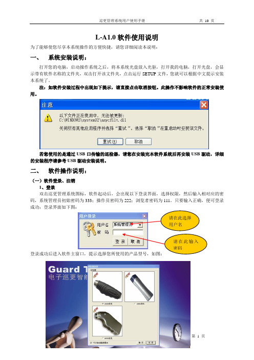
L-A1.0软件使用说明为了能够使您尽享本系统操作的方便快捷,请您详细阅读本说明:一、系统安装说明:打开您的电脑,启动操作系统之后,将本系统光盘放入光驱,打开我的电脑,打开光盘,会显示带有软件名称的文件夹,双击打开该文件夹,点击运行SETUP文件,您就可以根据中文提示安装本系统了。
注:如软件安装过程中出现如下提示,请直接点击取消按钮。
此操作不影响软件的正常安装使用。
若您使用的是通过USB口传输的巡检器,请您在安装完本软件系统后再安装USB驱动,详细的安装程序请参考USB驱动安装说明。
二、软件操作说明:(一)软件登录、注销1、登录双击巡更管理系统图标,软件起动后,会出现以下登录界面,选择权限,然后输入相对应的密码,系统管理员初始密码为333;操作员密码为222;浏览者密码为111。
只要输入正确,便可登录成功;登录界面如下图:登录成功后进入软件主窗口,提示选择您所使用的产品型号,如图:请在此选择用户名请在此输入密码2、注销操作员的注销,即更换操作员,使新的操作员用新的权限登录。
注销方法(如下图),选择菜单“操作员 用户注销”来实现。
点击此处即可(二)资源设置资源设置分五部分组成:人员钮设置、地点钮设置、事件设置、棒号设置、系统设置,每一部分的设置如下:1、系统设置:在第一次进入软件后,应首先对系统进行设置。
系统设置分为基本信息写入和权限用户密码管理。
如下图,在此可输入公司名称、选择的串口号,并可在此对权限密码进行修改。
修改完毕点击保存即可。
在此修改密码注:巡检器与电脑是用串口进行数据传输的,默认使用的串口号为COM1,巡检器与电脑是用USB 口传输的,默认使用的串口号为COM3(具体情况可到设备管理器中查询),在系统设置完毕后请重新登录巡更系统。
2、棒号设置:在使用巡检器之前需要将巡检器的棒号输入到软件中,以便识别。
点击“资源设置—>棒号设置”。
将巡检器与计算机连接好,并且将巡检器打开。
点击采集数据,会出现如下图所示:1140为该棒号码。
Basics of Twin Head Calibration v1.0

Basics of Twin Head Calibration HF TWIN HEAD 校准校准大步骤•1,D轴零点校准•2,Z轴零点校准•3,真空零点校准•4,TWIN HEAD 校准•5,NOZZLE CHANGER 校准1,D轴零点校准1.1在大致知道D轴值的情况下(在+/-5度范围内),按下述步骤校准进入SITEST主界面,点击进入TWINHEAD 界面此处选择所要校准的TWIN HEAD 编号(靠近里面的是1号,外面的是2号)轴选择区所选的轴当前位置轴命令区轴回零轴到达指定位置轴做连续运动轴的参数区图形界面说明一般在TWIN HEAD 头上都有原始的D轴零点值(不是很精确),把此值记下,写入到D轴零点位置。
1,在轴的选项里选择D轴2,点击POSITION,2:点击EDIT ,在此处写入D 轴的值,然后选择ACCEPT接受退出1:此处的勾要去掉,否则出入的是digit ,而我们头上抄下来的单位是度注意此处的单位是1/100度若知道此头的十分确切的D 轴零点值,则下面的步骤可省1,头回一下零2,悬臂回一下零2:选择校准D轴零点1:退出来后点击此处,进入校准TWIN HEAD 界面若头上所设吸嘴为516之外的其它吸嘴,此对话框将出现,则需到吸嘴设置那里去改为516。
2:所要校准的TWIN HEAD 上必须得是516,若不是,则改过来设为5161:点击进入到吸嘴设置界面,来设置吸嘴选择校准D轴零点再回到校准TWIN HEAD 界面吸嘴设置正确后将进入此界面,若开始就设置正确的,则直接进入此界面。
(提示只有在偏差+/-5度范围内有效)将如图所示的校准吸嘴装到所要校准的TWINHEAD 上,再在上面出现的界面上点击OK。
标志点D轴校准的特殊吸嘴校准后出现下面的界面,反复多较几次,直到两个值相等或个位相差1。
直到两个值相等或个位相差1 ,则校准完成1.2若D轴零点值丢失或在校准时由于范围超出+/-5度而校准时D轴数值出不来,则按照下述方法校准D轴零点点击进入POSITION,把零点值改为0ZPC改为0,接受后退回上一界面将D轴校准吸嘴装到所选的TWIN HEAD 上,并单击此处让D轴回零把轴控卡上相对应的D轴伺服关掉TWIN HEAD 1D轴伺服开关位置TWINHEAD2D轴伺服开关位置关掉伺服后,用手手动转动吸嘴,使标志点的方向正对进板方向(朝向Y轴马达的方向)标志点D轴校准的特殊吸嘴1,在这里切换到Z轴一下,在切换回D轴2,读出此处的值3:点击此处把读出的值写入此处写入读出的值把D轴伺服打上,并单击此处让D轴回零选择校准D轴零点;到了这里,步骤和上面介绍的一样,直到两个值相等或相差1为止。
- 1、下载文档前请自行甄别文档内容的完整性,平台不提供额外的编辑、内容补充、找答案等附加服务。
- 2、"仅部分预览"的文档,不可在线预览部分如存在完整性等问题,可反馈申请退款(可完整预览的文档不适用该条件!)。
- 3、如文档侵犯您的权益,请联系客服反馈,我们会尽快为您处理(人工客服工作时间:9:00-18:30)。
SOF_CUH_MULTIHEAD_V1(0) 多振镜头模块使用说明
版本记录
版本号更新日期更新人更新说明V1.0 2008-05-26 马成军
目录
功能模块说明 (1)
模块参数定义 (1)
加工界面 (1)
参数设置 (2)
功能模块说明
所谓多振镜头控制就是用一台电脑控制多个振镜头打标,它既可以用于一台激光器带多个振镜头的加工模式,也可以用于多台激光器带多个振镜头的加工模式。
EzCad2软件的plug目录下的“MultiHead.plg”文件是多振镜头控制模块文件。
当Ezcad2启动时会自动在plug目录下查找此文件,找到此文件后在系统的“激光”菜单栏会生成“MultiHead”菜单,如图1所示。
注:多头控制模块与通用EzCad2软件扩展模块(如分割标刻,旋转标刻等)不兼容,不能共存于plug目录下。
图1
模块参数定义
加工界面
点击菜单栏中“激光(L)”按钮下的“MultiHead”会弹出对话框如图2所示。
以两振镜头加工为例。
图2多头控制界面
零件:表示当前被加工完的零件总数。
此参数为电脑自动记数,不可人为更改,它后面的“R”按钮为清零按钮。
零件总数:表示当前要加工的零件总数,在连续加工模式下无效。
不在连续加工模式下时,如果此零件总数大于1,则加工时会重复加工直到加工的零件数等于零件总数才停止。
连续加工:表示一直重复加工当前文件,中间不停顿。
标刻(F2):开始加工,直接按键盘F2键即可执行此命令。
参数(F3):当前设备的参数。
直接按键盘F3键即可执行此命令。
退出(F5):退出本界面。
参数设置
点击“参数(F3)”按钮,打开“参数”对话框,如图3所示:
图3
工作模式的选择:
单激光器和多振镜头模式:点选此项表示使用软件控制一个激光器配合多个振镜工作。
多激光器和多振镜头模式:点选此项表示使用软件控制多个激光器配合多个振镜工作。
加工内容的选择:
所有振镜头加工相同工件:不同的振镜头标刻同一个工件。
所有振镜头加工不同工件:不同的振镜头标刻出不同的工件。
“振镜头1”/“振镜头2”按钮:点击按钮弹出“振镜头”参数设置框如图4所示:
图4
区域尺寸:振镜对应的实际最大标刻范围。
在一般情况下我们把“区域尺寸”、“工作空间”和我们所使用的场镜的最大“适用”范围设置成相同数值。
(分割、拼接、旋转打标除外)。
偏移X:标刻出来的内容在X方向上的偏移距离。
偏移Y:标刻出来的内容在Y方向上的偏移距离。
振镜1=x :表示控制卡的振镜输出信号1作为用户坐标系的x轴。
振镜2=x :表示控制卡的振镜输出信号2作为用户坐标系的x轴。
反向: 表示当前振镜的输出反向。
伸缩比例,默认值为100%。
当标刻出的实际尺寸和软件图示尺寸不同时,需要修改此参数。
当标刻出的实际尺寸比设计尺寸小时,增大此参数值;当标刻出的实际尺寸比设计尺寸大时,减小此参数值。
表示桶形或枕形失真校正系数,默认系数为 1.0(参数范围0.875-1.125) 。
表示平行四边形校正系数,默认系数为1.0(参数范围0.875-1.125) 。
表示平行梯形校正系数,默认系数为1.0(参数范围0.875-1.125)。
注意:如果激光振镜有变形,则必须先调整完变形后再调整伸缩比例。
颜色:在这里设定加工空间边界的颜色。
最小坐标:表示加工空间边界在X/Y轴负方向上的最小坐标。
中心坐标:表示加工空间边界在X/Y轴方向上的中心坐标。
最大坐标:表示加工空间边界在X/Y轴正方向上的最大坐标。
开始标刻延时:对于整个打标文件的准标刻延时。
结束标刻延时:对于整个打标文件的标刻后延时。
变换:我们的加工是由两个激光头配合完成的,但是人为装配存在的误差以及机械误差
的存在,为了得到理想的标刻效果,我们在软件中设置了矫正参数。
X:由于两个激光头配合误差的存在,在X方向上可能产生重叠和分离的效果,我们通过此参数可以矫正这些误差,标刻出满意的效果。
Y:由于两个激光头配合误差的存在,在Y方向上可能产生错位重叠和分离的效果,我们通过此参数可以矫正这些误差,标刻出满意的效果。
角度:如果两个振镜头没有平行放置,那么两个振镜头标刻出来的内容就会存在一定的角度,通过此参数可以矫正这些误差,标刻出满意的效果。