GNS3环境下做vrrp实验
vrrp备份实验报告

vrrp备份实验报告VRRP备份实验报告摘要:本实验旨在研究VRRP(虚拟路由冗余协议)在网络中的应用,通过搭建实验环境并进行测试,验证VRRP在网络故障发生时的备份能力和故障转移效果。
实验结果表明,VRRP能够有效地实现路由器的冗余备份,并在主路由器故障时快速实现故障转移,保障网络的稳定运行。
1. 引言VRRP是一种用于实现路由器冗余备份的协议,通过将多个路由器组成一个虚拟路由器,其中一个路由器作为主路由器,其余路由器作为备份路由器,实现了在主路由器故障时快速切换到备份路由器,从而保障网络的连续性和稳定性。
本实验旨在验证VRRP在实际网络中的应用效果,为网络管理员提供参考和指导。
2. 实验环境本实验使用了三台路由器和若干台主机组成了一个小型网络环境,其中两台路由器配置了VRRP协议,一台路由器作为主路由器,另一台路由器作为备份路由器。
主机通过交换机连接到路由器,构成了一个简单的局域网。
3. 实验过程在实验过程中,首先配置了VRRP协议的相关参数,包括VRRP组号、虚拟IP 地址、优先级等。
然后模拟了主路由器故障的情况,观察备份路由器是否能够快速接管主路由器的工作,并保障网络的正常通信。
通过抓包和日志记录等方式,对VRRP协议的故障转移过程进行了详细的分析和评估。
4. 实验结果实验结果表明,VRRP协议能够有效地实现路由器的冗余备份,并在主路由器故障时快速实现故障转移,保障了网络的稳定运行。
在故障发生后,备份路由器能够迅速接管主路由器的工作,主机能够无缝地切换到备份路由器,并继续正常通信。
实验数据显示,故障转移时间在毫秒级别,基本不会对网络通信产生明显的影响。
5. 结论通过本实验的研究和测试,验证了VRRP协议在网络中的应用效果,证明了其在实现路由器冗余备份和故障转移方面的优越性能。
VRRP协议能够为网络管理员提供一种简单而有效的解决方案,保障网络的连续性和稳定性,具有较高的实用价值和推广前景。
GNS环境下做vrrp实验

VRRP实验在这个实验配置了两个VRRP组——vrrp 1和vrrp 2。
在vrrp 1中,路由器R1为主虚拟路由器,R2为备用虚拟路由器;在vrrp 2中,路由器R1为备用虚拟路由器,路由器R1为主虚拟路由器。
在两个路由器都正常工作的时候,PC1和PC2通过R1访问远端R3。
路由器R1的具体配置:R1(config-if)#int s1/0R1(config-if)#ip addR1(config-if)#no shutdownR1(config-if)#int f0/0R1(config-if)#ip addressR1(config-if)#no shutdownR1(config-if)#vrrp 1 ipR1(config-if)#vrrp 1 priority 200 // Priority change will have no effect whilst interface is VRRP address ownerR1(config-if)#vrrp 1 preemptR1(config-if)#vrrp 2 ipR1(config-if)#vrrp 2 priority 100R1(config-if)#vrrp 2 preemptR1(config-if)#exitR1(config)#router ripR1(config)#ver 2R1(config)#networkR1(config)#networkR1(config)#no auto-summary路由器R2的配置:R2(config-if)#int s1/0R2(config-if)# ip addressR2 (config-if)#no shutdownR2 (config-if)#int f0/0R2 (config-if)#ip addressR2 (config-if)#no shutdownR2 (config-if)#vrrp 1 ipR2 (config-if)#vrrp 1 priority 150R2 (config-if)#vrrp 1 preemptR2 (config-if)#vrrp 2 ipR2 (config-if)#vrrp 2 priority 200R2 (config-if)#vrrp 2 preemptR2 (config-if)#exitR2 (config)#router ripR2 (config)#ver 2R2 (config)#networkR2 (config)#networkR2 (config)#no auto-summary路由器R3的配置:R3(config-if)#int s0/0R3(config-if)# ip addressR3(config-if)#no shutdownR3(config-if)#int s0/1R3(config-if)# ip addressR3(config-if)#no shutdownR3 (config)#router ripR3 (config)#ver 2R3 (config)#networkR3 (config)#networkR3 (config)#no auto-summaryR1#show vrrp briInterface Grp Pri Time Own Pre State Master addr Group addr Fa0/0 1 255 3003 Y Y MasterFa0/0 2 100 3609 Y BackupR1#show vrrp allFastEthernet0/0 - Group 1State is MasterVirtual IP address isVirtual MAC address is Advertisement interval is secPreemption enabledPriority is 255 (cfgd 200)Master Router is (local), priority is 255Master Advertisement interval is secMaster Down interval is secFastEthernet0/0 - Group 2State is BackupVirtual IP address isVirtual MAC address is Advertisement interval is secPreemption enabledPriority is 100Master Router is , priority is 255Master Advertisement interval is secMaster Down interval is sec (expires in sec)在路由器R2上:R2#show vrrp briInterface Grp Pri Time Own Pre State Master addr Group addr Fa0/0 1 150 3414 Y BackupFa0/0 2 255 3003 Y Y MasterR2#show vrrp all 省略实验做完了,当然,大家也可以通过关闭接口等方法来验证VRRP是否有效果~。
VRRP的配置实验报告

实验报告班级组号两人一组,找班干部要组号联络人组长同组人组成员课程名称计算机网络实验日期10月23日实验名称实验五 VRRP的配置成绩实验目的:1.能够配置VRRP;2. 通过实验了解PC的网关是通过VRRP形成的浮动地址;3. 通过实验了解网关冗余协议VRRP是如何来保护pc网关的。
实验条件:计算机、eNSP实验内容:实验拓扑图:配置思路:在SwitchA和SwitchB上创建VRRP备份组1和VRRP备份组2,在备份组1中,配置SwitchA为Master设备,SwitchB为Backup设备;在备份组2中,配置SwitchB为Master 设备,SwitchA为Backup设备,实现流量的负载均衡。
PC1与PC2的IP配置:SWA的配置(SWB反过来):在SwitchA上创建VRRP备份组1,配置SwitchA的优先级为120,抢占延时为20秒,作为Master设备;在SwitchA上创建VRRP备份组2, SwitchA的优先级为缺省值,作为Backup设备。
在SwitchA上创建VRRP备份组1配置SwitchA的优先级为120,抢占延时为20秒,在SwitchA上创建VRRP备份组2配置SwitchA的优先级为默认,在SwitchB上创建VRRP备份组2,配置SwitchB的优先级为120,抢占延时为20秒,作为Master设备;在SwitchB上创建VRRP备份组1, SwitchB的优先级为缺省值,作为Backup设备。
在SwitchB上创建VRRP备份组2配置SwitchB的优先级为120,抢占延时为20秒,测试:实验总结:通过这次实验我学会了如何配置VRRP协议以及此协议要解决的问题。
通过配置VRRP协议实现流量的负载均衡,保证可靠性。
在配置时要注意IP地址的配置,三层接口的创建等。
神州数码交换机VRRP实验

实验三十八、交换机VRRP实验一、 实验目的1、熟悉VRRP协议的使用方式和配置方法;2、理解VRRP协议的适用场合。
二、 应用环境VRRP和HSRP具有类似的功能,实现方法上略有不同,VRRP是由IETF提出,是一个标准协议,HSRP是由CISCO公司制定的。
VRRP(Virtual Router Redundancy Protocol,虚拟路由器冗余协议)是一种容错协议,运行于局域网的多台路由器上,它将这几台路由器组织成一台“虚拟”路由器,或称为一个备份组(Standby Group)。
在VRRP备份组内,总有一台路由器或以太网交换机是活动路由器(Master),它完成“虚拟”路由器的工作;该备份组中其它的路由器或以太网交换机作为备份路由器(Backup,可以不只一台),随时监控Master的活动。
当原有的Master出现故障时,各Backup将自动选举出一个新的Master来接替其工作,继续为网段内各主机提供路由服务。
由于这个选举和接替阶段短暂而平滑,因此,网段内各主机仍然可以正常地使用虚拟路由器,实现不间断地与外界保持通信。
三、 实验设备1、DCRS-7604(或6804)交换机2台2、HUB或交换机1台3、PC机2-4台4、Console线1-2根5、直通网线若干根五、 实验要求1、在交换机7604A和交换机7604B上分别划分基于端口的VLAN:交换机 VLAN 端口成员 IP1 24 10.1.157.1/24DCRS-7604A100 1 192.168.100.1/2410 8-16 192.168.10.1/24DCRS-7604B1 24 10.1.157.2/24100 1 192.168.100.2/2420 8-16 192.168.20.1/242、PC1-PC4的网络设置为:设备 IP地址 gateway MaskPC1 192.168.100.101 192.168.100.1255.255.255.0PC2 192.168. 100.102 192.168.100.1255.255.255.0PC3 192.168.10.2 192.168.10.1 255.255.255.0PC4 192.168.20.2 192.168.20.1 255.255.255.03、验证:无论拔掉192.168.100.1的线还是192.168.100.2的线,PC1和PC2不需要做网络设置的改变都可以与PC3和PC4通信。
VRRP实验

VRRP基本配置一、实验拓扑:二、实验配置:1.SWA与SWB之间跑Trunk.[SWA]interface Ethernet 1/0/1[SWA-Ethernet1/0/1]port link-type trunk[SWA-Ethernet1/0/1]port trunk permit vlan all[SWA-Ethernet1/0/1]quit[SWB]interface Ethernet 1/0/1[SWB-Ethernet1/0/1]port link-type trunk[SWB-Ethernet1/0/1]port trunk permit vlan all[SWB-Ethernet1/0/1]quit2.创建VLAN 20[SWA]vlan 20[SWA-vlan20]quit[SWA][SWB]vlan 20[SWB-vlan20]quit[SWB]3.跑VRRP[SWA]interface Vlan-interface 20[SWA-Vlan-interface20]ip address 192.168.2.101 255.255.255.0[SWA-Vlan-interface20]vrrp vrid 1 virtual-ip 192.168.2.100[SWA-Vlan-interface20]vrrp vrid 1 priority 120[SWA-Vlan-interface20]vrrp vrid 1 preempt-mode[SWA-Vlan-interface20]vrrp vrid 1 timer advertise 30[SWA-Vlan-interface20]vrrp vrid 1 authentication-mode md5 cisco[SWA-Vlan-interface20]quit[SWA][SWB]interface Vlan-interface 20[SWB-Vlan-interface20]ip address 192.168.2.102 255.255.255.0[SWB-Vlan-interface20]vrrp vrid 1 virtual-ip 192.168.2.100[SWB-Vlan-interface20]vrrp vrid 1 priority 100[SWB-Vlan-interface20]vrrp vrid 1 preempt-mode[SWB-Vlan-interface20]vrrp vrid 1 timer advertise 30[SWB-Vlan-interface20]vrrp vrid 1 authentication-mode md5 cisco[SWB-Vlan-interface20]quit[SWB]%Apr 2 00:11:47:154 2000 SWA L2INF/5/VLANIF LINK STATUS CHANGE:- 1 -Vlan-interface20 is UP%Apr 2 00:11:47:265 2000 SWA VRRP/5/MasterChange:- 1 -Vlan-interface20 | Virtual Router 1 : INITIALIZE --> BACKUP reason: Received interface event%Apr 2 00:11:47:455 2000 SWA IFNET/5/UPDOWN:- 1 -Line protocol on the interfaceVlan-interface20 is UP%Apr 2 00:13:17:144 2000 SWA VRRP/5/MasterChange:- 1 -Vlan-interface20 | Virtual Router 1 : BACKUP --> MASTER reason: Fail receiving VRRP advertisement message in 3 times Advertisement_Interval[SWA]dis vrrp verboseRun Method : VIRTUAL-MACVirtual Ip Ping : DisableInterface : Vlan-interface20VRID : 1 Adver. Timer : 30Admin Status : UP State : MasterConfig Pri : 120 Run Pri : 120Preempt Mode : YES Delay Time : 0Auth Type : MD5 Key :5W97B'/VOV+Q=^Q`MAF4<1!!Virtual IP : 192.168.2.100Virtual MAC : 0000-5e00-0101Master IP : 192.168.2.101[SWA][SWB]display vrrp verboseRun Method : VIRTUAL-MACVirtual Ip Ping : DisableInterface : Vlan-interface20VRID : 1 Adver. Timer : 30Admin Status : UP State : BackupConfig Pri : 100 Run Pri : 100Preempt Mode : YES Delay Time : 0Auth Type : MD5 Key : 5W97B'/VOV+Q=^Q`MAF4<1!!Virtual IP : 192.168.2.100Master IP : 192.168.2.101%Apr 2 00:12:39:444 2000 SWB L2INF/5/VLANIF LINK STATUS CHANGE:- 1 -Vlan-interface20 is UP%Apr 2 00:12:39:555 2000 SWB VRRP/5/MasterChange:- 1 -Vlan-interface20 | Virtual Router 1 : INITIALIZE --> BACKUP reason: Received interface event%Apr 2 00:12:39:745 2000 SWB IFNET/5/UPDOWN:- 1 -Line protocol on the interface Vlan-interface20 is UP三、实验总结:。
冗余网络配置实验(使用VRRP协议).doc
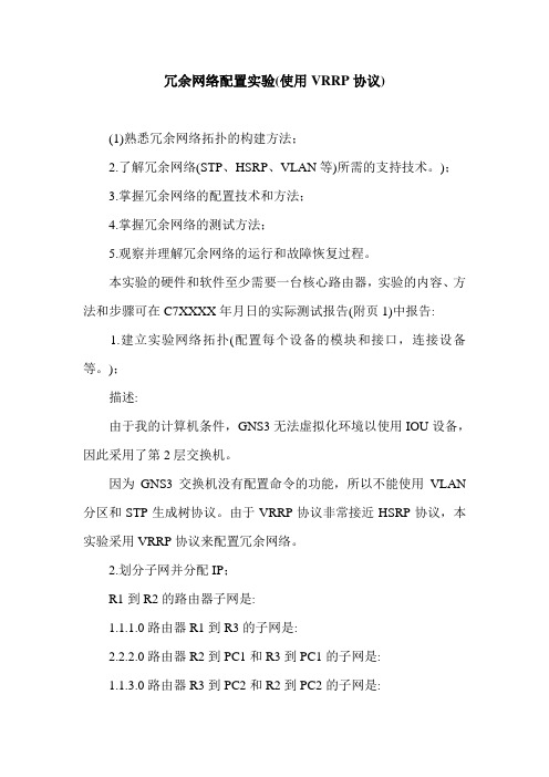
冗余网络配置实验(使用VRRP协议)(1)熟悉冗余网络拓扑的构建方法;2.了解冗余网络(STP、HSRP、VLAN等)所需的支持技术。
);3.掌握冗余网络的配置技术和方法;4.掌握冗余网络的测试方法;5.观察并理解冗余网络的运行和故障恢复过程。
本实验的硬件和软件至少需要一台核心路由器,实验的内容、方法和步骤可在C7XXXX年月日的实际测试报告(附页1)中报告:1.建立实验网络拓扑(配置每个设备的模块和接口,连接设备等。
);描述:由于我的计算机条件,GNS3无法虚拟化环境以使用IOU设备,因此采用了第2层交换机。
因为GNS3交换机没有配置命令的功能,所以不能使用VLAN 分区和STP生成树协议。
由于VRRP协议非常接近HSRP协议,本实验采用VRRP协议来配置冗余网络。
2.划分子网并分配IP;R1到R2的路由器子网是:1.1.1.0路由器R1到R3的子网是:2.2.2.0路由器R2到PC1和R3到PC1的子网是:1.1.3.0路由器R3到PC2和R2到PC2的子网是:2.2.4.03、完整清晰的标注端口和配置信息;R2的端口配置:(1) s1/0端口:(2) f0/0端口:(3) f2/0端口:R3的端口配置:(1) s1/0端口:(2) f0/0端口:(3) f2/0端口:R1港配置:(1) s2/0端口:(2) s2/1端口:PC1端口的IP配置:PC2端口IP配置:4.配置VRRP协议;在R2配置VRRP协议:在R3上配置VRRP协议:5.配置OSPF协议;在R1配置OSPF协议:在R2配置OSPF协议:在R3上配置OSPF协议:6.检查路由器的VRRP协议配置:要检测R2上的VRRP配置:要检测R3上的VRRP配置:实际测试结果(附页2)1、测试整个网络的连通性;使用PC1 ping PC2:使用PC2 ping PC1:使用路由器R2 ping R1:使用路由器R2 ping R3:2.测试冗余链路连通性的链路故障模拟:当路由器R2断开链路S1/0和f2/0时,当PC1 ping通PC2:路由器R3断开链路S1/0时,PC2 ping通PC1:真实测试结(附页3)经过这次路由冗余配置实验,我意识到配置路由的原理并不困难,但在配置之前有许多事情要准备。
VRRP配置实验报告
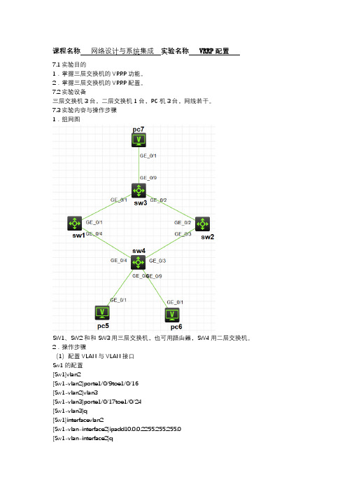
课程名称网络设计与系统集成实验名称VRRP配置7.1实验目的1.掌握三层交换机的VRRP功能。
2.掌握三层交换机的VRRP配置。
7.2实验设备三层交换机3台,二层交换机1台,PC机3台,网线若干。
7.3实验内容与操作步骤1.组网图SW1、SW2和和SW3用三层交换机,也可用路由器,SW4用二层交换机。
2.操作步骤(1)配置VLAN与VLAN接口Sw1的配置[Sw1]vlan2[Sw1-vlan2]porte1/0/9toe1/0/16[Sw1-vlan2]vlan3[Sw1-vlan3]porte1/0/17toe1/0/24[Sw1-vlan3]q[Sw1]interfacevlan2[Sw1-vlan-interface2]ipadd10.0.0.2255.255.255.0[Sw1-vlan-interface2]q[Sw1]interfacevlan3[Sw1-vlan-interface3]ipadd20.0.0.1255.255.255.0 Sw2的配置[Sw2]vlan2[Sw2-vlan2]porte1/0/9toe1/0/16[Sw2-vlan2]vlan3[Sw2-vlan3]porte1/0/17toe1/0/24[Sw2-vlan3]q[Sw2]interfacevlan2[Sw2-vlan-interface2]ipadd10.0.0.3255.255.255.0 [Sw2-vlan-interface2]q[Sw2]interfacevlan3[Sw2-vlan-interface3]ipadd30.0.0.1255.255.255.0 Sw3的配置[Sw3]vlan2[Sw3-vlan2]porte1/0/1toe1/0/8[Sw3-vlan2]vlan3[Sw3-vlan3]porte1/0/9toe1/0/16[Sw3-vlan3]vlan416[Sw3-vlan4]porte1/0/17toe1/0/24[Sw3-vlan4]q[Sw3]interfacevlan2[Sw3-vlan-interface2]ipadd20.0.0.2255.255.255.0 [Sw3-vlan-interface2]q[Sw3]interfacevlan3[Sw3-vlan-interface3]ipadd30.0.0.2255.255.255.0 [Sw3-vlan-interface3]q[Sw3]interfacevlan4[Sw3-vlan-interface3]ipadd40.0.0.1255.255.255.0 (2)配置交换机之间的路由Sw1的配置[Sw1]rip[Sw1-rip-1]network10.0.0.0[Sw1-rip-1]network20.0.0.0Sw2的配置[Sw2]rip[Sw2-rip-1]network10.0.0.0[Sw2-rip-1]network30.0.0.0Sw3的配置[Sw3]rip[Sw3-rip-1]network30.0.0.0[Sw3-rip-1]network30.0.0.0[Sw3-rip-1]network40.0.0.0配置完成后,验证个交换机之间路由的是否正常。
单元任务书15_配置VRRP
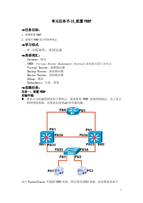
单元任务书15_配置VRRP♑任务目标:1、能够配置VRRP2、能够对VRRP进行排错和验证♑学习形式✧小组协作,共同完成♑英语词汇:Gateway:网关VRRP:Virtual Router Redundancy Protocol虚拟路由器冗余协议Virtual Router:虚拟路由器Backup Router:备份路由器Master Router:活跃路由器Debug:调试Redundancy:冗余,重复♑实践任务:任务一;配置VRRP实验环境:⏹格木公司组建的网络如下图所示,要求使用VRRP加强网络稳定,为了充分利用网络资源,还要求实现VLAN的负载均衡。
由于PacketTracer不能做VRRP实验,所以使用GNS3来做,拓扑图更改如下需求描述和规划:对于VLAN3:SW1为备份路由器、SW2为活跃路由器(2)在SW1交换机的VLAN虚接口的物理IP地址规划:VLAN2:192.168.2.1/24VLAN3:192.168.3.1/24(3)在SW2交换机的VLAN虚接口的物理IP地址规划:VLAN2:192.168.2.2/24VLAN3:192.168.3.2/24(4)PC1、PC2所连交换机端口分别加入VLAN2、VLAN3地址设置如下PC1的IP:192.168.2.10/24,网关192.168.2.254/24PC2的IP:192.168.3.10/24,网关192.168.3.254/24(5)SW1和R1的互联地址为192.168.0.0/30;SW2和R1的互联地址为192.168.1.0/30(6)配置R1路由器的Loopback接口地址为192.168.100.1/24,用来模拟外网地址(7)交换机之间的链路均为中继链路,并使用静态路由实现网络互通用路由器当做PC来使用的配置命令PC1(config)#no ip routingPC1(config)#interface fastEthernet 0/0PC1(config-if)#ip address 192.168.2.10 255.255.255.0PC1(config-if)#no cdp enablePC1(config-if)#no shutdownPC1(config-if)#exitPC1(config)#PC1(config)#ip default-gateway 192.168.2.254PC1(config)#exitPC1#推荐步骤:1、配置客户端地址PC1(config)#no ip routingPC1(config)#interface fastEthernet 0/0PC1(config-if)#ip address 192.168.2.10 255.255.255.0PC1(config-if)#no cdp enablePC1(config-if)#no shutdownPC1(config-if)#exitPC1(config)#PC1(config)#ip default-gateway 192.168.2.254PC1(config)#exitPC1#PC2(config)#no ip routingPC2(config)#interface fastEthernet 0/0PC2(config-if)#ip address 192.168.3.10 255.255.255.0PC2(config-if)#no cdp enablePC2(config-if)#no shutdownPC2(config-if)#exitPC2(config)#PC2(config)#ip default-gateway 192.168.3.254PC2(config)#exitPC2#2、在SW3中创建VLAN2、VLAN3,将f1/1、f1/2端口分别划分到VLAN2、VLAN3,f1/14、f1/15分别设为中继链路(trunk)SW3(config)#vlan 2SW3(config-vlan)#exSW3(config)#vlan 3SW3(config-vlan)#exSW3(config)#int f1/1SW3(config-if)#sw mo accSW3(config-if)#sw acc vlan 2SW3(config-if)#exSW3(config)#int f1/2SW3(config-if)#sw mo accSW3(config-if)#sw acc vlan 3SW3(config-if)#exitSW3(config)#int range f1/14 -15SW3(config-if-range)#sw tr encap dotSW3(config-if-range)#sw mo trSW3(config-if-range)#exitSW3(config)# no ip routing //此为二层交换机,关闭路由功能SW3(config)#3、SW1分别创建VLAN2、VLAN3,f1/14、f1/15设置为trunk中继链路,启用路由功能,f0/0端口改为路由口,设置IP地址192.168.0.1/30SW1(config)#vlan 2SW1(config-vlan)#exitSW1(config)#vlan 3SW1(config-vlan)#exitSW1(config)#int range f1/14 -15SW1(config-if-range)#sw tr encap dot1qSW1(config-if-range)#sw mo trSW1(config-if-range)#exitSW1(config)#ip routingSW1(config)#int f0/0 //SW1的f0/0默认为路由口,直接设置IP地址SW1(config-if)#ip add 192.168.0.1 255.255.255.252SW1(config-if)#no shutSW1(config-if)#exitSW1(config)#4、SW2分别创建VLAN2、VLAN3,f1/14、f1/15设置为trunk中继链路,启用路由功能,f0/0端口改为路由口,设置IP地址192.168.1.1/30SW2(config)#vlan 2SW2(config-vlan)#exitSW2(config)#vlan 3SW2(config-vlan)#exitSW2(config)#int range f1/14 -15SW2(config-if-range)#sw trunk encapsulation dot1qSW2(config-if-range)#sw mo trSW2(config-if-range)#exitSW2(config)#ip routingSW2(config)#int f0/0 //SW2的f0/0默认为路由口,直接设置IP地址SW2(config-if)#ip add 192.168.1.1 255.255.255.252SW2(config-if)#no shutSW2(config-if)#exitSW2(config)#5、R1分别设置f0/0、f0/1端口地址为192.168.0.2/30、192.168.1.2/30,设置Loopback地址为192.168.100.1/24Router(config)#host R1R1(config)#int f0/0R1(config-if)#ip add 192.168.0.2 255.255.255.252R1(config-if)#no shutR1(config-if)#exitR1(config)#int f0/1R1(config-if)#ip add 192.168.1.2 255.255.255.252R1(config-if)#no shutR1(config-if)#exitR1(config)#int loopback 0R1(config-if)#ip add 192.168.100.1 255.255.255.0R1(config-if)#no shutR1(config-if)#exR1(config)#6、设置静态路由,SW1、SW2分别设置静态默认路由用于连接外网。
- 1、下载文档前请自行甄别文档内容的完整性,平台不提供额外的编辑、内容补充、找答案等附加服务。
- 2、"仅部分预览"的文档,不可在线预览部分如存在完整性等问题,可反馈申请退款(可完整预览的文档不适用该条件!)。
- 3、如文档侵犯您的权益,请联系客服反馈,我们会尽快为您处理(人工客服工作时间:9:00-18:30)。
VRRP实验
在这个实验配置了两个VRRP组——vrrp 1和vrrp 2。
在vrrp 1中,路由器R1为主虚拟路由器,R2为备用虚拟路由器;在vrrp 2中,路由器R1为备用虚拟路由器,路由器R1为主虚拟路由器。
在两个路由器都正常工作的时候,PC1和PC2通过R1访问远端R3。
路由器R1的具体配置:
R1(config-if)#int s1/0
R1(config-if)#ip add 200.0.1.1 255.255.255.0
R1(config-if)#no shutdown
R1(config-if)#int f0/0
R1(config-if)#ip address 10.0.0.253 255.255.255.0
R1(config-if)#no shutdown
R1(config-if)#vrrp 1 ip 10.0.0.253
R1(config-if)#vrrp 1 priority 200 // Priority change will have no effect whilst interface is VRRP address owner
R1(config-if)#vrrp 1 preempt
R1(config-if)#vrrp 2 ip 10.0.0.254
R1(config-if)#vrrp 2 priority 100
R1(config-if)#vrrp 2 preempt
R1(config-if)#exit
R1(config)#router rip
R1(config)#ver 2
R1(config)#network 10.0.0.0
R1(config)#network 200.0.1.0
R1(config)#no auto-summary
路由器R2的配置:
R2(config-if)#int s1/0
R2(config-if)# ip address 200.0.2.1 255.255.255.0
R2 (config-if)#no shutdown
R2 (config-if)#int f0/0
R2 (config-if)#ip address 10.0.0.254 255.255.255.0
R2 (config-if)#no shutdown
R2 (config-if)#vrrp 1 ip 10.0.0.253
R2 (config-if)#vrrp 1 priority 150
R2 (config-if)#vrrp 1 preempt
R2 (config-if)#vrrp 2 ip 10.0.0.254
R2 (config-if)#vrrp 2 priority 200
R2 (config-if)#vrrp 2 preempt
R2 (config-if)#exit
R2 (config)#router rip
R2 (config)#ver 2
R2 (config)#network 10.0.0.0
R2 (config)#network 200.0.2.0
R2 (config)#no auto-summary
路由器R3的配置:
R3(config-if)#int s0/0
R3(config-if)# ip address 200.0.1.2 255.255.255.0
R3(config-if)#no shutdown
R3(config-if)#int s0/1
R3(config-if)# ip address 200.0.2.2 255.255.255.0
R3(config-if)#no shutdown
R3 (config)#router rip
R3 (config)#ver 2
R3 (config)#network 200.0.1.0
R3 (config)#network 200.0.2.0
R3 (config)#no auto-summary
R1#show vrrp bri
Interface Grp Pri Time Own Pre State Master addr Group addr
Fa0/0 1 255 3003 Y Y Master 10.0.0.253 10.0.0.253
Fa0/0 2 100 3609 Y Backup 10.0.0.254 10.0.0.254
R1#show vrrp all
FastEthernet0/0 - Group 1
State is Master
Virtual IP address is 10.0.0.253
Virtual MAC address is 0000.5e00.0101
Advertisement interval is 1.000 sec
Preemption enabled
Priority is 255 (cfgd 200)
Master Router is 10.0.0.253 (local), priority is 255
Master Advertisement interval is 1.000 sec
Master Down interval is 3.003 sec
FastEthernet0/0 - Group 2
State is Backup
Virtual IP address is 10.0.0.254
Virtual MAC address is 0000.5e00.0102
Advertisement interval is 1.000 sec
Preemption enabled
Priority is 100
Master Router is 10.0.0.254, priority is 255
Master Advertisement interval is 1.000 sec
Master Down interval is 3.609 sec (expires in 2.789 sec)
在路由器R2上:
R2#show vrrp bri
Interface Grp Pri Time Own Pre State Master addr Group addr
Fa0/0 1 150 3414 Y Backup 10.0.0.253 10.0.0.253
Fa0/0 2 255 3003 Y Y Master 10.0.0.254 10.0.0.254
R2#show vrrp all 省略
实验做完了,当然,大家也可以通过关闭接口等方法来验证VRRP是否有效果~。