Sliding mode control for mobile welding robot
VRTEX 移动虚拟现实焊接培训器说明说明书

EASILY TRANSPORTED from classroom toclassroom or to a recruitment event or openhouse. The VRTEX Mobile can be ready to goin a matter of minutes.BLENDED TRAINING SOLUTIONS FOR WELDING EDUCATIONTOUCHSCREEN USER INTERACTION providesequipment and procedural set-up on an intuitive,resistive touchscreen. All screens mirror theVRTEX 360, making transfer of interactionseamless between the systems.UNIVERSAL GUN HANDLE allows for connectionof a MIG/MAG gun attachment for GMAW andFCAW, and a stick attachment for SMAW welding.TABLETOP COUPON STAND easily attaches andstands on a standard table for welding and istaken apart for quick and simple storage insidethe VRTEX Mobile.The VRTEX systems are virtual reality arc welding training simulators. Thesecomputer based training systems are educational tools designed to supplementand enhance traditional welding training. They allow students to practice theirwelding technique in a simulated and immersive environment. The VRTEX systemspromote the efficient transfer of quality welding skills and body positioning tothe welding booth while reducing material waste associated with traditionalwelding training. The combination of realistic puddle, arc welding sound, andreal-time feedback tied to the welder’s movement provides a realistic andexciting, hands-on training experience.The VRTEX® Mobile is a basic, entry level welding training system. It is designedto provide mobility in an easy to use and engaging welding training tool. TheVRTEX Mobile is ideal for initial, basic welding training, as a recruitment andengagement tool for educational and industry and for employment and screeningfor human resources or as an evaluation tool for instructors and educators to geta baseline on student knowledge. The VRTEX Mobile is definitely on the move!VRTEX MOBILE PROVIDES:FLEXIBILITY» M ultiple welding processes and positions» V ariety of joint configurations» I nstructor tools allow modification basedon preferred welding program and styleINNOVATION» R ealistic welding puddle appearance and sounds» M agnetic tracking system provides accuratemeasurements for student score and evaluation» V irtual weld discontinuities appear in the weldwhen improper welding technique is usedCLASSROOM PERFORMANCE» Visual cues give real-time technique feedback» Advanced scoring system for student evaluation» E ncourages interaction — the instructor cancoach the welder while conducting virtualweld inspection» R ecord, archive and verify student work.CONSUMABLE ANDENVIRONMENTAL SAVINGS» No welding consumables, wire or waste» Track savings with the Weldometer™LANGUAGE SUPPORTEnglish, French, German, Spanish, Turkish,Japanese, Chinese (Mandarin), Portuguese(Brazilian), Russian, Korean, Hindi and ArabicDEMO MODE:Allows the instructor or student to view anexample weld or a demonstration of propertechnique, prior to a weld being madeREPLAY MODEAllows for instructor or student to reviewand analyze the welding processSET-UP AND INSTALLATION REQUIREMENTS:• T he VRTEX system requires minimal space for set-up. Dimensions are 8 W x 8 D x 8 H ft. (2.4 x 2.4 x 2.4 m).• W hen operating multiple units in one location, switch between standard and alternate frequency systems (unique part numbers are identified).• T he VRTEX Mobile system is not designed for operation in harsh environments. Recommendations are listed in the instruction manual.• A void magnetic fields, conductive and high frequency objects and processes.• A n uninterruptible power supply (UPS) may be required for protection of the system from power irregularities and/or disruptions.MC12-93 (06/15) © Lincoln Global, Inc. All Rights Reserved. Printed in U.S.A.CUSTOMER ASSISTANCE POLICYThe business of The Lincoln Electric Company is manufacturing and selling high quality welding equipment, consumables, and cutting equipment. Our challenge is to meet the needs of our customers and to exceed their expectations. On occasion, purchasers may ask Lincoln Electric for information or advice about their use of our products. Our employees respond to inquiries to the best of their ability based on information provided to them by the customers and the knowledge they may have concerning the application. Our employees, however, are not in a position to verify the information provided or to evaluate the engineering requirements for the particular weldment. Accordingly, Lincoln Electric does not warrant or guarantee or assume any liability with respect to such information or advice. Moreover, the provision of such information or advice does not create, expand, or alter any warranty on our products. Any express or implied warranty that might arise from the information or advice, including any implied warranty of merchantability or any warranty of fitness for any customers’ particular purpose is specifically disclaimed.Lincoln Electric is a responsive manufacturer, but the selection and use of specific products sold by Lincoln Electric is solely within the control of, and remains the sole responsibility of the customer. Many variables beyond the control of Lincoln Electric affect the results obtained in applying these types of fabrication methods and service requirements.Subject to Change – This information is accurate to the best of our knowledge at the time of printing. Please refer to for anyupdated information.。
点焊机的原理与制作方法

点焊机的原理与制作方法英文回答:The principle of a spot welding machine is based on the resistance heating principle. It involves joining two or more metal pieces together by applying pressure and passing an electric current through them. The heat generated by the electric current melts the metal at the contact points, and when the current is stopped, the molten metal solidifies, forming a strong bond.A spot welding machine consists of several key components. The main components include the power supply, electrodes, and a control system. The power supply provides the electric current required for welding. The electrodes, usually made of copper, are used to apply pressure and conduct the electric current to the metal pieces. The control system regulates the welding parameters such as the welding current, welding time, and electrode pressure.To create a spot welding machine, one needs to follow a few steps. First, the power supply needs to be selected based on the desired welding current and voltage. The power supply should be capable of delivering the required current to melt the metal at the contact points. Next, the electrodes need to be designed and fabricated. The electrodes should have good thermal conductivity to ensure efficient heat transfer and should be able to withstand the pressure applied during welding. Finally, a control system needs to be integrated to regulate the welding parameters and ensure consistent and reliable welds.Spot welding machines are widely used in various industries, such as automotive, construction, and manufacturing. They are particularly useful for joiningthin metal sheets or wires, such as in the production of car bodies or wire mesh. The speed and efficiency of spot welding make it a preferred method for mass production.中文回答:点焊机的原理基于电阻加热原理。
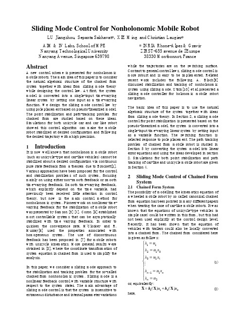
Sliding Mode Control for Nonholonomic Mobile Robot
Kylia MINT和WT-MINT延时线干涉仪产品说明书

w w w.k y l i a.c o m i n f o@k y l i a.c o m Delay Line InterferometersMINT and WT-MINT1 – Description……………………………………………………………………………………………………………………………………… p12 – Block diagrams……………………………………………………………………………………………………………………………….. p23 – Absolute maximum ratings……………………………………………………………………………………………………………… p34 – Operating conditions………………………………………………………………………………………………………………………. p35 – MINT specifications………………………………………………………………………………………………………………………… p46 – MINT statistic data………………………………………………………………………………………………………………………….. p67 – WT-MINT specifications………………………………………………………………………………………………………………….. p78 – Phase tuning options………………………………………………………………………………………………………………………. p99 – ER attenuation option…………………………………………………………………………………………………………………….. p1110 – IL attenuation option……………………………………………………………………………………………………………………. p1311 – Tunable coupling option……………………………………………………………………………………………………………….. p1312 – TAP option……………………………………………………………………………………………………………………………………. p1513 – Second input option……………………………………………………………………………………………………………………… p1514 – Wavelength range………………………………………………………………………………………………………………………… p1515 – Fiber type and connectors…………………………………………………………………………………………………………….. p1616 – Custom products…………………………………………………………………………………………………………………………… p1617 – Packages layout……………………………………………………………………………………………………………………………. p1618 – Revision………………………………………………………………………………………………………………………………………… p171 – DescriptionThe Micro Interferometer (MINT) is a Delay Line Interferometer (DLI) that performs the interference between an incoming signal and itself delayed by one bit-time. Dedicated to D(Q)PSK demodulation it can be used in many other applications. MINT is tunable to enable a precise matching of the carrier frequency. Two phase tuning options are available: the ultra-fast option (U), which exhibits very low tuning time constant (20µs), and the low voltage option (L), which needs only 3V to reach the tuning range.The WT-MINT is a Widely Tunable MINT that enables to set the delay of the interferometer to the desired value. This can be done either with a micrometer head (manual option) or with a motorized translation stage (piloted version). In both case U and L option are available to precisely match the carrier frequency. There are three ranges of WT-MINT:-WT-MINT 100ps: it enables to set an optical delay range of 100ps (corresponding to a Free Spectral Range of 10GHz to infinite, or – for instance – 5GHz to 10GHz). Available with manual or piloted option.-WT-MINT 300ps: it enables to set an optical delay range of 300ps (corresponding to a Free Spectral Range of 3.3GHz to infinite, or 2.5GHz to 10GHz). Available with manual or piloted option.-WT-MINT 3000ps: it enables to set an optical delay range of 3000ps (corresponding to a Free Spectral Range of 0.33GHz to infinite). Available with piloted option only.MINT and WT-MINT products are also available with PM fibers.MINT packagingWT-MINT packaging2 – Block diagrams50/50 platemirroroptical connectorBlock diagram: MINTBlock diagram: WT-MINTThe incoming signal is split in two parts. One is delayed regarding the other and then both are recombined on two outputs where they interfere one with each other. Both outputs are phase shifted by 180° and thus can be plugged to balanced or differential photodiodes that will convert a phase modulation into an amplitude modulation.The delay between both arms of the interferometer should be equal to the time-bit (T bit) of the incoming signal. Then the interferometer is characterized by its Free Spectral Range (FSR) which is linked to T bit by the relation FSR=1/T bit.3 – Absolute maximum ratingsParameter Symbol Min Typ. Max Unit Remarks/Conditions Maximal optical input power OpIn 300 mWStorage temperature range MINTSTR-40 80°C WT-MINT -10 40Humidity RH 5 85 % Non condensing Fiber bend radius 20 mmMaximum input voltage U optionV max100VL option44 – Operating conditionsParameter Symbol Min Typ. Max Unit Remarks/Conditions Operating wavelength OWR 1520 1570 nmOperating temperature range MINTOTR0 70°C WT-MINT 10 355 – MINT specificationsMINT, FSR > 2.5GHzParameterSymbol Min Typ. Max Unit Remarks/Conditions Free Spectral Range 1FSR 2.5 GHz Any FSR > 2.5GHz can be provided FSR accuracy 1ΔFSR 1 %FSR Insertion Losses 1 IL 2.0 dB IL uniformity 1ΔIL 0.5 dB Polarization Dependant Losses 1,2PDL 0.3 dB Polarization DependantFrequency Shift 1,2FSR>10GHz PDFS 2.0 %FSR FSR<10GHz4.0 Extinction Ratio 1ER 18 dB Polarization Extinction Ratio 1,3PER 20 25 dB Temperature Dependant Frequency Shift L TDFS 10 %FSR U50 Tuning range 1.5 FSRTuning voltage L V 3 V Voltage needed to reach the tuning range U 75 90 Tuning time constant L τ 1.0 s To reach 50% of the final state U 0.02 ms Power consumptionL P 0.5 W U 0.001 Polarization Mode Dispersion PMD 0.1 ps Chromatic Dispersion CD 1 ps/nm Optical Return Loss ORL 35 dB Skew0.5 1.0ps Packaging size 4FSR >= 20GHz44 x 26 x 9.5mm 3FSR < 20GHzor PM fiber any FSR100 x 55 x 16 Phase tuning connector 0.1 inch PIN headerFiber Pigtail Type SM SMF-28With 900µm loose tube PMPANDA PMFiber Pigtail Length0.91.01.1m1 measured over OTR and OWR for all states of polarization 2for Single Mode MINT 3for Polarization Maintaining MINT 4excluding fiber bootMINT, FSR < 2.5GHzParameterSymbol Min Typ. Max Unit Remarks/ConditionsFree Spectral Range 1FSR 0.4 2.5 GHz Any FSR between 400MHz and 2.5GHz can be providedFSR accuracy 1ΔFSR 5 %FSRInsertion Losses on short arm 1IL1 9.0 dB Including 6dB of natural losses due to beamsplitter Insertion Losses on long arm 1 IL2 9.0 dB Polarization Extinction Ratio 1,3 PER 20 25 dB Tuning range 1.5 FSRTuning voltage L V 3 V Voltage needed to reach the tuning range U 75 90 Tuning time constant L τ 1.0 s To reach 50% of the final state U 0.02 ms Power consumptionL P 0.5 W U0.001 Polarization Mode Dispersion PMD 0.1 ps Chromatic Dispersion CD 1 ps/nm Optical Return Loss ORL 35 dB Skew0.51.0ps Packaging size 4130 x 65 x 19.5 mm 3Phase tuning connector 0.1 inch PIN headerFiber Pigtail Type SM SMF-28With 900µm loose tube PMPANDA PMFiber Pigtail Length0.91.01.1m1 measured over OTR and OWR for all states of polarization 2for Single Mode MINT 3for Polarization Maintaining MINT 4excluding fiber boot6 – MINT statistic dataHere are the statistic data of our MINT delivered between January 2009 and March 2013 (any FSR from 2.5Hz to 100GHz, any phase tuning option).For PDFS and ER, we do not observe Gaussian repartition because these parameters depend on the FSR (larger is the FSR, better are PDFS and ER).0%5%10%15%20%25%30%> -2> -1.8> -1.6> -1.4> -1.2> -1> -0.8> -0.6> -0.4> -0.2% o f M I N T d e l i v e r e dIL (dB)(> -1 means -1.2dB > IL > -1.0dB)0%10%20%30%40%50%0< 0.05< 0.1< 0.15< 0.2< 0.25< 0.3< 0.35% o f M I N T d e l i v e r e dPDL (dB)(< 0.3 means 0.3dB > PDL > 0.25dB)0%5%10%15%20%< 0< 0.2< 0.4< 0.6< 0.8< 1< 1.2< 1.4< 1.6< 1.8< 2< 2.2< 2.4< 2.6< 2.8< 3% o f M I N T d e l i v e r e d (F S R > 10G H z )PDFS (%FSR)(< 3 means 3% > PDFS > 2.8%)0%5%10%15%20%> 17> 18> 19> 20> 21> 22> 23> 24> 25> 26> 27> 28> 29> 30% o f M I N T d e l i v e r e dER (dB)(> 18 means 19dB > ER > 18dB)7 – WT-MINT specificationsThe 100ps WT-MINT allows a tunable FSR from 10GHz to infinite.WT-MINT, 100ps Optical Delay RangeParameter Symbol Min Typ. Max Unit Remarks/Conditions Optical Delay RangeODR 100 ps Manual WT-MINT ODR sensitivity 8 fs M o t o r i z e d W T -M I N TMinimum incremental motion 2 fs Relative accuracy75 fs Unidirectional repeatability 15 fs Bidirectional repeatability20 fs Insertion Losses 1 IL 2.5 dB IL uniformity 1ΔIL0.5 dB Polarization Dependant Losses 1,2PDL 0.5 dB Polarization Dependant Frequency Shift 1,2PDFS 3.0 %FSR Extinction Ratio 1ER18 dB Polarization Extinction Ratio 1,3PER 20 25 dB Tuning range 1.5 FSRTuning voltage L V 3 V Voltage needed to reach the tuning range U 75 90 Tuning time constant L τ 1.0 s To reach 50% of the final state U 0.02 ms Power consumptionL P 0.5 W U0.001 Polarization Mode Dispersion PMD 0.1 ps Chromatic Dispersion CD 1 ps/nm Optical Return Loss ORL 35 dB Skew0.5 1.0ps Packaging size 4216 x 92 x 40mm 3Phase tuning connectorBNCFiber Pigtail TypeSM SMF-28With 900µm loose tubePMPANDA PM1 measured over ODR, OTR and OWR for all states of polarization 2for Single Mode WT-MINT 3for Polarization Maintaining WT-MINT 4excluding micrometer head or piloted actuatorThe 300ps WT-MINT allows a tunable FSR from 3.3GHz to infinite or 2.5GHz to 10GHz.WT-MINT, 300ps Optical Delay RangeParameter Symbol Min Typ. Max Unit Remarks/Conditions Optical Delay RangeODR 300 ps Manual WT-MINT ODR sensitivity 15 fs M o t o r i z e d W T -M I N TMinimum incremental motion 3 fs Relative accuracy150 fs Unidirectional repeatability 30 fs Bidirectional repeatability40 fs Insertion Losses 1 IL 4.0 dB IL uniformity 1ΔIL1.0 dB Polarization Dependant Losses 1,2PDL 0.8 dB Polarization Dependant Frequency Shift 1,2PDFS 5.0 %FSR Extinction Ratio 1ER15 dB Polarization Extinction Ratio 1,3PER 20 25 dB Tuning range 1.5 FSRTuning voltage L V 3 V Voltage needed to reach the tuning range U 75 90 Tuning time constant L τ 1.0 s To reach 50% of the final state U 0.02 ms Power consumptionL P 0.5 W U0.001 Polarization Mode Dispersion PMD 0.1 ps Chromatic Dispersion CD 1 ps/nm Optical Return Loss ORL 35 dB Skew0.5 1.0ps Packaging size 4216 x 92 x 40mm 3Phase tuning connectorBNCFiber Pigtail TypeSM SMF-28With 900µm loose tubePMPANDA PM1 measured over ODR, OTR and OWR for all states of polarization 2for Single Mode WT-MINT 3for Polarization Maintaining WT-MINT 4excluding micrometer head or piloted actuatorThe 3ns WT-MINT allows a tunable FSR from 0.33GHz to infinite. The 12ns WT-MINT allows a tunable FSR from 83MHz to infinite.WT-MINT, 3ns to 12ns Optical Delay RangeParameter Symbol Min Typ. Max Unit Remarks/Conditions Optical Delay Range ODR 3000 ps Minimum incremental motion3ns delay 10 fs 12ns delay 40 Relative accuracy 3ns delay 250 fs 12ns delay 1000 Unidirectional repeatability3ns delay 30 fs 12ns delay 120 Bidirectional repeatability3ns delay 150 fs12ns delay600 Insertion Losses on short arm 1 IL1 9.0 dB Including 6dB of natural losses due to beamsplitter Insertion Losses on long arm 1IL2 9.0 dB Polarization Extinction Ratio 1,2PER 20 25 dB Tuning range1.5 FSRTuning voltage L V 3 V Voltage needed to reach the tuning range U 75 90 Tuning time constant L τ 1.0 s To reach 50% of the final state U 0.02 ms Power consumptionL P 0.5 W U0.001 Polarization Mode Dispersion PMD 0.1 ps Chromatic Dispersion CD 1 ps/nm Optical Return Loss ORL 35 dB Skew0.5 1.0ps Packaging size 750 x 400 x 129Phase tuning connectorBNCFiber Pigtail TypeSM SMF-28With 900µm loose tubePMPANDA PM1measured over ODR, OTR and OWR for all states of polarization 2for Polarization Maintaining WT-MINT8 – Phase tuning optionsFor DPSK demodulation, the phase tuning is essential in order to control the contrast between both outputs of the interferometer/demodulator.The FSR variation is not significant (and can be considered as invariant) when the user adjust the phase of the demodulator/interferometer.KYLIA proposes for all its DPSK demodulators (MINT and WT-MINT) two different phase tuning options: U option:Ultra-fast response based on a piezo actuator.This option is helpful for fast shifting systems (instability of the laser for instance). The DLI can adapt itself instantaneously to the environment, if a closed loop between BER and phase shifting is set up. This solution is mainly used in labs.Using the phase tuning, theuser can adjust the demodulator phase in order to match with the low contrast between outputshigh contrast between outputs thanks to phase tuningWith this option, the utuning time is better thTuning sL option: Low-voltage tuning basPhase shift is obtainedvoltage changes the locWith this option, the utuning time is better9 – ER attenuation optionIt is possible to tune the extinction ratipower is the same the ER will be the grThe ER attenuation option for MINT anof one arm of the interferometer. It enan accuracy of 1dB.Block dthe user can accomplish a shift of one FSR by applyiter than 20µs.ning speed for a U option DPSK demodulatorng based on a resistive heatertained using a resistive heater fixed on an optical ehe local temperature and thus the optical index, thenthe user can accomplish a shift of one FSR by applyter than 1s.n ratio of an interferometer by adjusting the power inthe greatest. By attenuating the power in one arm, ERINT and WT-MINT consist of a micrometer head that. It enables to tune the ER down to 0dB (one arm is tock diagram: DLI with ER attenuation optionapplying a 60V voltage. Theical element. Changing thethen the optical delay.applying a 2V voltage. Thewer in both arms. When them, ER will be reduced.d that can adjust the powerm is totally shut down) withOn the following graph, we show the variation of the spectral response of our DLI by attenuating the optical beam for one arm of the interferometer.MINT spectral response with ER attenuationMINT with ER attenuation option-40-35-30-25-20-15-10-50193360193370193380193390193400193410I L (d B )frequency (GHz)position (mm)=0position (mm)=0.05position (mm)=0.10position (mm)=0.15position (mm)=0.20position (mm)=0.25position (mm)=0.27position (mm)=0.28position (mm)=0.29position (mm)=0.30position (mm)=0.31position (mm)=0.32position (mm)=0.33position (mm)=0.34position (mm)=0.35position (mm)=0.36position (mm)=0.37position (mm)=0.38position (mm)=0.39position (mm)=0.40micrometer head for ER attenuationWT-MINT with ER attenuation option10 – IL attenuation optionIL attenuation enables to increase the IL on each output individually. This can be done thanks to a micrometer head. The attenuation can be total (no power exits from the output) and adjusted with an accuracy of 0.1dB.Block diagram: DLI with IL attenuation option11 – Tunable coupling optionThis option is available for PM MINT or PM WT-MINT only. It enables to adjust the splitting ratio of the interferometer (which is 50/50 for standard interferometers) from 100/0 to 0/100. This can be very useful if a precise 50/50 ratio is needed.micrometer head for ER attenuationmicrometer head for FSR tuningBNC connector for phase tuningBlock diagram: DLI with tunable coupling optionWT-MINT PM with tunable coupling and ER attenuation optionsBNC connector for phase tuning12 – TAP optionThanks to the flexibility of our technology, we can propose to add optical TAP outputs in our products. The TAP ratio can be 4% or 50%.Block diagram: MINT with TAP option for input and output signals13 – Second input optionA second input can also be added in our product.Block diagram: MINT with a second optical input14 – Wavelength rangeMINT and WT-MINT can be proposed at different wavelength range, from the visible to the IR 800nm, 1064nm, 1300nm…). The device will be operational on a wavelength range of a tens of nanometers centered on the wavelength required by customer.15 – Fiber type and connectorsEvery MINT or WT-MINT can be proposed either with SM or PM fibers.The devices can be proposed with any kind of connectors (FP/UPC, FC/APC, SC/PC, SC/APC, LC/PC, E2000/PC, E2000/APC, etc…).16 – Custom productsThanks to our free-space technology we can easily customize most of our products and so it is for the MINT and WT-MINT. Customer can feel free to ask for any customization they need. We will examine the request and do our best to have a positive answer.17 – Packages layoutMINT packaging : FSR > 20GHz MINT packaging : FSR > 2.5GHzMINT packaging : FSR < 2.5GHzWT-MINT packaging (with ER attenuation option)18 – Revisiondate version ObjectMarch 21, 2013 MINT V1.0 CreationMay 15, 2014 MINT V1.1 Phase tuning option explanationMINT packaging for FSR < 2.5GHz February 3rd, 2015 MINT V1.2 Added 12ns delay WTMINT。
林肯电子Vantage 300多功能焊接机说明书

© Lincoln Global, Inc. All Rights Reserved.300ENGINE DRIVEN WELDERSProcessesStick, TIG, MIG, Flux-Cored, Gouging Product Number K2409-3See back for complete specsShown: K2409-3PH: +1.216-481-8100 • Output Range See Back PageRated Output Current/Voltage/Duty Cycle 300A/32V/100% 350A/28V/100%Number of Cylinders 4HP @ Speed (RPM) 22 HP @ 1800 RPM Weight/Dimensions (H x W x D) 1035 lbs. (469 kg) 35.9 x 25.3 x 60.0 in. (913 x 642 x 1524 mm) 44.3 (1124 mm) To Top ofExhaust Tubethe U.S.A. and Canada.Chopper Technology® delivers extremely fast response for tighter output control.VRD™ portion of nameplatewith green light on.Vantage ® 300 | [ 3 ]Single-side engine access with lockable sliding door.Fuel, oil pressure and engine temperature gauges help you monitor performance.Latched and lockable radiator cap cover.Convenient battery tray below control panel.Handy oil drain valve and tube makes oil changes neat.Output automatically switches toremote mode when remote device is connected. For the CC-stick,downhill pipe and Touch Start TIG ®modes, the machine output dial becomes a maximum current limit for more fine tuning with the remote control dial or Amptrol ™.1. Glow Plug Button2. Weld Mode Selector Switch3. Run/Stop Switch4. Hour Meter5. Start Pushbutton6. Engine Idler Switch7. Fuel Level, Engine Temperature and Oil Pressure Gauges 8. Engine Protection Light 9. Engine Battery Charging Light 10. 120 VAC Circuit Breakers 11. 120 VAC Receptacles12. Covered Weld Output Terminals + and - 13. Sealed GFCI Modules 14. Ground Stud15. 120/240 VAC Full-KVA 1-Phase Receptacle 16. 240 VAC Full-KVA 3-Phase Receptacle 17. Full-KVA 1- & 3-Phase Circuit Breaker 18. 14-Pin Wire Feeder Connector 19. 6-Pin Remote Control Connector20. Arc Force & Inductance/Pinch Control Dial 21. Welding Terminals Control Switch 22. Wire Feeder Voltmeter Polarity Switch 23. Digital Amps and Volts Output Meters 24. VRD ™ Indicator Lights 25. Output Control DialNote: Control panel door not shown.211232221201917161514181********• Simple Controls – Keeps training time to a minimum. The flip-down control panel door keeps less frequently used dials out of the way. Scratch-resistant Lexan ® nameplate.• Digital meters for amps and volts output make it easy to precisely set your procedures.• Large 20 gallon (76 liter) fuel tank provides run time for an extended day – over 16 hours of welding at 300A/32V/100% duty cycle output, or 49 hours at high idle.• The Kubota ® V1505 engine is a 22 horsepower, water-cooled, 4cylinder diesel engine with an automatic idler for greater fuel economy and reduced noise. • Engine hour meter makes it easy to schedule maintenance.• LN-25 Ironworker ™ arcoss-the-arc wire feeder is a recommended option.• 14-pin connector for Lincoln Electric wire feeders with control cables: LF-72, LF-74, LN-8, LN-15, LN-25 PRO Dual Power, and LN-742. Also compatible with Magnum ® SG spool gun system.• Two Vantage ® 300 units can be paralleled in the CC-stick mode to increase output.• Kilowatts available for Multi-Weld ® 350 use: 4.8 KW @ 60 VDC, 7.0 KW @ 58 VDC.KEY CONTROLS[ 4 ] | Vantage ® 300• Simple wire harnessing keeps connections to a minimum for greater reliability. Lead and harness strain reliefs on all control connections help ensure trouble-free performance.• Engine protection system includes automatic shutdown for low oil pressure or high engine temperature.• Indicator light turns on for low oil pressure or high engine temperature. A second indicator light turns on if the engine battery charging system malfunctions.• Circuit breaker protection on the battery ignition system provides added component protection.• Environmental friendly engine! The engine has a closed breathersystem to keep the engine compartment and ground clean. This system eliminates oil mist from collecting inside the engine compartment, especially on surfaces that would lower engine cooling efficiency.• Self-bleeding engine simplifies startup if your fuel tank runs dry.• Kubota ® engine camshaft is gear-driven. No timing belt maintenance.• Printed circuit boards are environmentally-shielded using Lincoln Electric’s engineered potting and protective frame trays.• Dependability and long life are aided by all-copper windings in rotor and stator with high quality insulation.• Standard stainless steel roof, side panels and engine-access doordeliver added protection, durability and corrosion-resistance. Eliminates the need to paint or replace rusting panels.• Manufactured under a quality system certified to ISO 9001 requirements and ISO 14001 environmental standards.• Canadian Standards Association (CSA) certified.• Three-year Lincoln Electric warranty (parts and labor) on welder(engine is warranted separately by the manufacturer).(1)High Altitude: For maximum rating, derate the output 2.5% to 3.5% for every 1,000 ft. (300 m). High Temperature: For maximum rating, derate 2 volts for every 18°F (10°C) above 104°F (40°C).(2) DC Constant Voltage capability provides convenience and added safety when welding in electrically hazardous conditions.(3) When welding, available AC generator power will be reduced. Output voltage is within +/- 10% at all loads up to rated capacity.(4) 120V will operate either 60 Hz or 50/60 Hz power tools, lights, etc.(5) Circuits cannot be wired in parallel to operate the same device.(6)Kubota ® warranty is 2 years/2,000 hours for machines shipped within the U.S., Canada, Pacific Ocean region and Western Europe. Warranty is 1 year/1,000 hours for Central and South America, Asia, Africa and Middle East.Vantage ® 300 |[ 5 ]One-Pak ® Welding PackageOrder a Lincoln Electric One-Pak ® and get everything you need to complete a welding package - all with one order number.(Package requires assembly.)Unassembled Package Contains:• Vantage ® 300• Medium Welder Trailer (K2636-1)• Duo-Hitch ™ 2 in. (51 mm) Ball/Lunette Eye Hitch (included)• Fender and Light Kit (K2639-1)• Cable Rack (K2640-1)• Cable Connectors - two (K2487-1)• Electrode Cable 2/0, two 50 ft. (15.3 m) lengths (K2485-2)• Electrode Cable 2/0, 10 ft. (3 m) (K2483-2)• Work Cable 2/0, 50 ft. (15.3 m) (K2484-2)• 300A Electrode Holder (K909-7)• 300A Work Clamp (K910-1)Order:K2452-3 Vantage ® 300 Kubota ® One-Pak ® PackageReady-Pak ® Welding PackageOrder a Lincoln Electric Ready-Pak ® Package and get an assembled welding pletely Assembled Package Contains:• Vantage ® 300• Medium Welder Trailer (K2636-1)• Duo-Hitch ™ 2 in. (51 mm) Ball/Lunette Eye Hitch (included)• Fender and Light Kit (K2639-1)• Cable Rack (K2640-1)• Cable Connectors - two (K2487-1)• Electrode Cable 2/0, two 50 ft. (15.3 m) lengths (K2485-2)• Electrode Cable 2/0, 10 ft. (3 m) (K2483-2)• Work Cable 2/0, 50 ft. (15.3 m) (K2484-2)• 300A Electrode Holder (K909-7)• 300A Work Clamp (K910-1)Order:K2453-3 Vantage ® 300 Kubota ® Ready-Pak ®PackageK2636-1 Medium Welder TrailerVantage ® 300Duo-Hitch ™ 2 in. (51 mm) Ball/Lunette Eye Hitch(included)K2640-1 Cable RackCompletely Assembled Ready-Pak ®Pkg.[ 6 ] | Vantage ® 300GENERAL OPTIONSPower Plug Kit (20A)Provides four 120V plugs rated at 20 amps each, and one dual voltage, full KVA (1-Phase) plug rated at 120/240V, 50 amps. 120V plug may not be compatible with common household receptacles. Order K802NFull-KVA Power Plug (1-Phase) One dual voltage plug rated at120/240V, 50 amps. NEMA 14-50P. Order T12153-9Full-KVA Power Plug (3-Phase) One plug rated at 240V, 50 amps. NEMA 15-50P. Order T12153-10Full - KVA Adapter Kit (1-Phase) Provides convenient connection of Lincoln Electric equipment having a 240V AC 1-phase plug (NEMA 6-50P) to the full-KVA receptacle on Lincoln engine-driven welders. Order K1816-1Medium Welder TrailerFor heavy-duty road, off-road, plant and yard use. Includes pivoting jack stand, safety chains, and 13 in. (330 mm) wheels. Stiff .120 in. (3.0 mm) welded rectangular steel tube frame construction is phosphate etched and powder coat painted for superior rust and corrosion resistance. Low sway suspension gives outstanding stability with manageable tongue weight. Wheel bearings are packed with high viscosity, high pressure, low washout Lubriplate ® grease. Includes a Duo-Hitch ™ – a 2 in. (51 mm) Ball/Lunette Eyecombination hitch. Overall width 60 in. (1524 mm). Overall length 124 in. (3150 mm). Order:K2636-1 TrailerK2639-1 Fender & Light Kit K2640-1 Cable RackFour-Wheeled Steerable Yard TrailerFor off-road, plant and yard use. Includes an automatically engaging drawbar lock when the drawbar is raised to the verticle position. 13 in. (330 mm) wheels. Wheel bearings are packed with high viscosity, high pressure, low washout Lubriplate ® grease. Stiff 3/16 in. (4.8 mm) welded rectangular steel frame construction is phosphate etched and powder-coat painted for superior rust and corrosion resistance. Also includes aDuo-Hitch ™ – a 2 in. (51 mm) Ball/Lunette Eye combination hitch. Overall width 55 in. (1397 mm). Overall length 124 in. (3150 mm). Order K 2641-2Spark Arrestor KitMounts to muffler exhaust tube. Virtually eliminates spark emissions. Order K1898-1Digital Weld Meters Kit Easy-to read digital meters for volts and amps. Easy to install. (For K2409-1 and K2499-1). Order K2467-1Polarity/Multi-Process Switch For easy polarity switching. Example: DC-stick root pass on pipe & DC+ stick for hot, fill and cap passes. Also for an easy process change. Example: DC+ stick root pass on pipe and DC- Innershield ® self-shielded flux-cored wire for hot, fill and cap passes. 6 & 14-pin remote connections can be made to this unit. For all Lincoln ElectricChopper Technology ® engine-driven welders. Mounts on roof with K2663-1 Docking Kit. Order K2642-1Docking KitSecures the K2642-1 Polarity/Multi-Process Switch to the engine-driven welder roof. Release latch permits removal of K2642-1 Polarity/Multi-Process Switch. Made from stainless steel for rust-free operation. For all Lincoln Electric ChopperTechnology ® engine-driven welders.Order K2663-1STICK OPTIONSAccessory KitIncludes 35 ft. (10.7 m) 2/0 electrode cable with lug, 30 ft. (9.1 m) 2/0 work cable with lugs, headshield, filter plate, cover plate, work clamp and electrode holder. 400 amp capacity. Order K704Remote Output ControlConsists of a control box with choice of two cable lengths. Permits remote adjustment of output.Order K857 for 25 ft. (7.6 m) K857-1 for 100 ft. (30.5 m)Remote Output Control with 120VAC ReceptaclesRemote weld output control box with two 120V AC receptacles having GFCI (Ground Fault Circuit Interrupter) protection. One cord for both remote and power. 100 ft. (30.5 m) length. Permits remote adjustment of weld output andpower for tools (such as a grinder) at the work. 20 amp capacity. Order K2627-2TIG OPTIONSPro-Torch ™ PTA-26V TIG Torch Air-cooled 200 amp torch (2 piece) equipped with valve for gas flow control. 25 ft. (7.6 m) length. Order K1783-9Magnum ® Parts Kit for PTA-26V TIG TorchMagnum ® Parts Kit provides all the torch accessories you need to start welding. Parts Kit provides collets, collet bodies, a back cap, alumina nozzles and tungstens in a variety of sizes, all packaged in an easy to carry reclosable sack. Order KP509Foot Amptrol ™Provides 25 ft. (7.6 m) of remote output control for TIG welding. (6-pin plug connection). Order K870Hand Amptrol ™Provides 25 ft. (7.6 m) of remote current control for TIG welding. 6-pin plug connection). Velcro straps secure torch. Order K963-3(one size fits all Pro-Torch ™ TIG Torches)Square Wave ™ TIG 175For AC TIG Welding with square wave performance, use the AC generator of the engine-driven welder to supply the power (full rated output may not be available). Easy setup. Includes torch, foot Amptrol ™ and gas regulator and hose. Requires the K1816-1 Full KVA Adapter Kit. Order K1478-5Invertec ® V205-T AC/DC One-Pak ® Pkg.For AC TIG welding with square wave performance, use the AC generator of the engine-driven welder to supply the power. Easy setup. Includes torch, parts kit, regulator and hose kit, Twist Mate ™ torch adapter, work cable with Twist Mate ™ end and Foot Amptrol ™. Requires K1816-1 Full-KVA Adapter Kit.Order K2350-2WIRE FEEDER OPTIONSLN-25 Ironworker™ Wire Feeder P ortable CV unit for flux-cored and MIG welding with MAXTRAC® wiredrive system. Includes digital metersfor wire feed speed/amperageand voltage, gas solenoid, internalcontactor and 5/64 in. (2.0 mm)drive roll kit for cored wire. Has 83%reduced wire feed speed capabilityfor 6 o’clock pipe welding withInnershield® wire.Order K2614-9K126 PRO Innershield® GunFor self-shielded wire with 15 ft.(4.5 m) cable. For .062-5/64 in.(1.6-2.0 mm) wire. IncludesK466-10 Connector Kit.Order K126-12Drive Roll and Guide Tube KitFor .068-.072 in. (1.7-1.8 mm)cored or solid steel wire.Order KP1697-068Magnum® PRO 350 Ready-Pak®15 ft., .035-5/64 in.Magnum® PRO MI G/flux-coredwelding guns are rated 100%duty cycle. The guns are designedfor high amperage, high dutycycle applications in extremeenvironments where heat-resistanceand fast serviceability are key.Order K2652-2-10-45Drive Roll and Guide Tube KitFor .035 in. and .045 in.(0.9-1.1 mm) solid steel wire.Order KP1696-1Magnum® SG Spool GunHand held semiautomatic wirefeeder. Requires SG Control Moduleand Input Cable.Order K487-25SG Control ModuleThe interface between the powersource and the spool gun. Providescontrol of the wire speed and gasflow. For use with a spool gun.Order K488Input Cable(For SG Control Module)For Lincoln Electric engine powersources with 14-pin MS-typeconnection, separate 115V NEMAreceptacles and output studconnections.Order K691-10PLASMA CUTTINGTomahawk® 1000Cuts metal using the AC generatorpower from the engine-drivenwelder. Requires the T12153-9Full-KVA Power Plug (1-Phase).Order K2808-1Vantage® 300 | [ 7 ]C U S T O M E R A S S I S T A N C E P O L I C YThe business of The Lincoln Electric Company is manufacturing and selling high quality welding equipment, consumables, and cutting equipment. Our challenge is to meet the needs of our customers and to exceed their expectations. On occasion, purchasers may ask Lincoln Electric for information or advice about their use of our products. Our employees respond to inquiries to the best of their ability based on information provided to them by the customers and the knowledge they may have concerning the application. Our employees, however, are not in a position to verify the information provided or to evaluate the engineering requirements for the particular weldment. Accordingly, Lincoln Electric does not warrant or guarantee or assume any liability with respect to such information or advice. Moreover, the provision of such information or advice does not create, expand, or alter any warranty on our products. Any express or implied warranty that might arise from the information or advice, including any implied warranty of merchantability or any warranty of fitness for any customers’ particular purpose is specifically disclaimed.Lincoln Electric is a responsive manufacturer, but the selection and use of specific products sold by Lincoln Electric is solely within the control of, and remains the sole responsibility of the customer. Many variables beyond the control of Lincoln Electric affect the results obtained in applying these types of fabrication methods and service requirements.Subject to Change – This information is accurate to the best of our knowledge at the time of printing. Please refer to for any updated information.For best welding results with Lincoln Electric equipment,always use Lincoln Electric consumables. Visit for more details.。
模具成形不良用语英汉对照

模具成形不良用语英汉对照 时间:2005-07-11 14:35 阿里巴巴-机械论坛aberration 色差 atomization ?化bank mark ?料纹 bite 咬入blacking hole 涂料孔(铸疵) blacking scab 涂料疤blister 起泡 blooming 起霜blow hole 破孔 blushing 泛白body wrinkle 侧壁皱纹 breaking-in 冒口带肉bubble 膜泡 burn mark 糊斑burr 毛边 camber 翘曲cell 气泡 center buckle 表面中部波皱check 细裂痕 checking 龟裂chipping 修整表面缺陷 clamp-off 铸件凹痕collapse 塌陷 color mottle 色斑corrosion 腐蚀 crack 裂痕crazing 碎裂 crazing 龟裂deformation 变形 edge 切边碎片edge crack 裂边 fading 退色filler speak 填充料斑 fissure 裂纹flange wrinkle 凸缘起皱 flaw 刮伤flow mark 流痕 galling 毛边glazing 光滑 gloss 光泽grease pits 污斑 grinding defect 磨痕haircrack 发裂 haze 雾度incrustation 水锈 indentation 压痕internal porosity 内部气孔mismatch 偏模mottle 斑点 necking 缩颈nick 割痕 orange peel 橘皮状表面缺陷overflow 溢流 peeling 剥离pit 坑 pitting corrosion 点状腐蚀plate mark 模板印痕 pock 麻点pock mark 痘斑 resin streak 树脂流纹resin wear 树脂脱落 riding 凹陷sagging 松垂 saponification 皂化scar 疤痕 scrap 废料scrap jam 废料阻塞 scratch 刮伤/划痕scuffing 深冲表面划伤 seam 裂痕shock line 模口挤痕 short shot 充填不足shrinkage pool 凹孔 sink mark 凹痕skin inclusion 表皮折叠straightening 矫直streak 条状痕 surface check 表面裂痕surface roughening 橘皮状表皮皱折surging 波动sweat out 冒汗 torsion 扭曲warpage 翘曲 waviness 波痕webbing 熔塌 weld mark 焊痕whitening 白化 wrinkle 皱纹组装、冲压、喷漆等专业词汇Assembly line组装线Layout布置图Conveyer流水线物料板Rivet table拉钉机Rivet gun拉钉枪Screw driver起子Electric screw driver电动起子Pneumatic screw driver气动起子worktable 工作桌OOBA开箱检查fit together组装在一起fasten锁紧(螺丝)fixture 夹具(治具)pallet栈板barcode条形码barcode scanner条形码扫描仪fuse together熔合fuse machine热熔机repair修理operator作业员QC品管supervisor 课长ME制造工程师MT制造生技cosmetic inspect外观检查inner parts inspect内部检查thumb screw大头螺丝lbs.inch镑、英寸EMI gasket导电条front plate前板rear plate后板chassis |'∫[$aelig]si| 基座bezel panel面板power button电源按键reset button重置键Hi-pot test of SPS高源高压测试Voltage switch of SPS电源电压接柆键sheet metal parts 冲件plastic parts塑料件SOP制造作业程序material check list物料检查表work cell工作间trolley台车carton纸箱sub-line支线left fork叉车personnel resource department 人力资源部production department生产部门planning department企划部QC Section品管科stamping factory冲压厂painting factory烤漆厂molding factory成型厂common equipment常用设备uncoiler and straightener整平机punching machine 冲床robot机械手hydraulic machine油压机lathe车床planer |'plein[$#61611]|刨床miller铣床grinder磨床driller钻床linear cutting线切割electrical sparkle电火花welder电焊机staker=reviting machine铆合机position职务president董事长general manager总经理special assistant manager特助factory director厂长department director部长deputy manager |'depjuti| =vice manager副理section supervisor课长deputy section supervisor =vice section superisor 副课长group leader/supervisor组长line supervisor线长assistant manager助理to move, to carry, to handle搬运be put in storage入库pack packing包装to apply oil擦油to file burr 锉毛刺final inspection终检to connect material接料to reverse material 翻料wet station沾湿台Tiana天那水cleaning cloth抹布to load material上料to unload material卸料to return material/stock to退料scraped |'skr[$aelig]pid|报废scrape ..v.刮;削deficient purchase来料不良manufacture procedure制程deficient manufacturing procedure制程不良oxidation |' ksi'dei[$#61611]n|氧化scratch刮伤dents压痕defective upsiding down抽芽不良defective to staking铆合不良embeded lump|in'bed| |l[$#61657]mp|镶块feeding is not in place送料不到位stamping-missing漏冲production capacity生产力education and training教育与训练proposal improvement提案改善spare parts=buffer备件forklift叉车trailer=long vehicle拖板车compound die合模die locker锁模器pressure plate=plate pinch压板bolt螺栓name of a department部门名称administration/general affairs dept总务部automatic screwdriver电动启子thickness gauge厚薄规gauge(or jig)治具power wire电源线buzzle蜂鸣器defective product label不良标签identifying sheet list标示单screwdriver holder起子插座pedal踩踏板stopper阻挡器flow board流水板hydraulic handjack油压板车forklift叉车pallet栈板glove(s)手套glove(s) with exposed fingers割手套thumb大拇指forefinger食指midfinger中指ring finger无名指little finger小指band-aid创可贴iudustrial alcohol工业酒精alcohol container沾湿台head of screwdriver起子头sweeper扫把mop拖把vaccum cleaner吸尘器rag 抹布garbage container灰箕garbage can垃圾箱garbage bag垃圾袋chain链条jack升降机production line流水线chain链条槽magnetizer加磁器lamp holder灯架to mop the floor拖地to clean the floor扫地to clean a table擦桌子air pipe 气管packaging tool打包机packaging打包missing part漏件wrong part错件excessive defects过多的缺陷critical defect极严重缺陷major defect主要缺陷minor defect次要缺陷not up to standard不合规格dimension/size is a little bigger尺寸偏大(小) cosmetic defect外观不良slipped screwhead/slippery screw head螺丝滑头slipped screwhead/shippery screw thread滑手speckle斑点mildewed=moldy=mouldy发霉rust生锈deformation变形burr(金属)flash(塑件)毛边poor staking铆合不良excesssive gap间隙过大grease/oil stains油污inclusion杂质painting peel off脏污shrinking/shrinkage缩水mixed color杂色scratch划伤poor processing 制程不良poor incoming part事件不良fold of pakaging belt打包带折皱painting make-up补漆discoloration羿色water spots水渍polishing/surface processing表面处理exposed metal/bare metal金属裸露lack of painting烤漆不到位safety安全quality品质delivery deadline交货期cost成本engineering工程die repair模修enterprise plan = enterprise expansion projects企划QC品管die worker模工production, to produce生产equipment设备to start a press开机stop/switch off a press关机classification整理regulation整顿cleanness清扫conservation清洁culture教养qualified products, up-to-grade products良品defective products, not up-to-grade products不良品waste废料board看板feeder送料机sliding rack滑料架defective product box不良品箱die change 换模to fix a die装模to take apart a die拆模to repair a die修模packing material包材basket蝴蝶竺plastic basket胶筐isolating plate baffle plate; barricade隔板carton box纸箱to pull and stretch拉深to put material in place, to cut material, to input 落料to impose lines压线to compress, compressing压缩character die字模to feed, feeding送料transportation运输(be)qualfied, up to grade合格not up to grade, not qualified不合格material change, stock change材料变更feature change 特性变更evaluation评估prepare for, make preparations for 准备parameters参数rotating speed, revolution转速manufacture management制造管理abnormal handling异常处理production unit生产单位lots of production生产批量steel plate钢板roll material卷料manufacture procedure制程operation procedure作业流程to revise, modify修订to switch over to, switch---to throw--over switching over切换engineering, project difficulty工程瓶颈stage die工程模automation自动化to stake, staking, reviting铆合add lubricating oil加润滑油shut die架模shut height of a die架模高度analog-mode device类模器die lifter举模器argon welding氩焊vocabulary for stamping冲压常词汇stamping, press冲压punch press, dieing out press冲床uncoiler & strainghtener整平机feeder送料机rack, shelf, stack料架cylinder油缸robot机械手taker取料机conveyer belt输送带transmission rack输送架top stop上死点bottom stop下死点one stroke一行程inch寸动to continue, cont.连动to grip(material)吸料location lump, locating piece, block stop 定位块reset复位smoothly顺利dent压痕scratch刮伤deformation变形filings铁削to draw holes抽孔inquiry, search for查寻to stock, storage, in stock库存receive领取approval examine and verify审核processing, to process加工delivery, to deliver 交货to return delivenry to. to send delinery back to retrn of goods退货registration登记registration card登记卡to control管制to put forward and hand in提报safe stock安全库存acceptance = receive验收to notice通知application form for purchase请购单consume, consumption消耗to fill in填写abrasion磨损reverse angle = chamfer倒角character die字模to collect, to gather收集failure, trouble故障statistics统计demand and supply需求career card履历卡to take apart a die卸下模具to load a die装上模具to tight a bolt拧紧螺栓to looser a bolt拧松螺栓to move away a die plate移走模板easily damaged parts易损件standard parts标准件breaking.(be)broken,(be)cracked 断裂to lubricate润滑common vocabulary for die engineering模具工程常用词汇die 模具figure file, chart file图档cutting die, blanking die冲裁模progressive die, follow (-on)die连续模compound die复合模punched hole冲孔panel board镶块to cutedges=side cut=side scrap切边to bending折弯to pull, to stretch拉伸Line streching, line pulling线拉伸engraving, to engrave刻印upsiding down edges翻边to stake铆合designing, to design设计design modification设计变化die block模块folded block折弯块sliding block滑块location pin定位销lifting pin顶料销die plate, front board模板padding block垫块stepping bar垫条upper die base上模座lower die base下模座upper supporting blank上承板upper padding plate blank上垫板spare dies模具备品spring 弹簧bolt螺栓document folder活页夹file folder资料夹to put file in order整理资料spare tools location手工备品仓first count初盘人first check初盘复棹人second count 复盘人second check复盘复核人equipment设备waste materials废料work in progress product在制品casing = containerazation装箱quantity of physical invetory second count 复盘点数量quantity of customs count会计师盘,点数量the first page第一联filed by accounting department for reference会计部存查end-user/using unit(department)使用单位summary of year-end physical inventory bills年终盘点截止单据汇总表bill name单据名称This sheet and physical inventory list will be sent to accounting department together (Those of NHK will be sent to financial department)本表请与盘点清册一起送会计部-(NHK厂区送财会部)Application status records of year-end physical inventory List and physical inventory card 年终盘点卡与清册使用-状况明细表blank and waste sheet NO.空白与作废单号plate电镀mold成型material for engineering mold testing工程试模材料not included in physical inventory不列入盘点sample样品incoming material to be inspected进货待验description品名steel/rolled steel钢材material statistics sheet物料统计明细表meeting minutes会议记录meeting type 会别distribution department分发单位location地点chairman主席present members出席人员subject主题conclusion结论decision items决议事项responsible department负责单位pre-fixed finishing date预定完成日approved by / checked by / prepared by核准/审核/承办PCE assembly production schedule sheetPCE组装厂生产排配表model机钟work order工令revision版次remark备注production control confirmation生产确认checked by初审approved by核准department部门stock age analysis sheet库存货龄分析表on-hand inventory现有库存available material良品可使用obsolete material良品已呆滞to be inspected or reworked待验或重工total合计cause description原因说明part number/ P/N 料号type形态item/group/class类别quality品质prepared by制表notes说明year-end physical inventory difference analysis sheet年终盘点差异分析表physical inventory盘点数量physical count quantity账面数量difference quantity差异量cause analysis原因分析raw materials原料materials物料finished product成品semi-finished product半成品packing materials包材good product/accepted goods/ accepted parts/good parts良品defective product/non-good parts不良品disposed goods处理品warehouse/hub仓库on way location在途仓oversea location海外仓spare parts physical inventory list备品盘点清单spare molds location模具备品仓skid/pallet栈板tox machine自铆机wire EDM线割EDM放电机coil stock卷料sheet stock片料tolerance工差score=groove压线cam block滑块pilot导正筒trim剪外边pierce剪内边drag form压锻差pocket for the punch head挂钩槽slug hole废料孔feature die公母模expansion dwg展开图radius半径shim(wedge)楔子torch-flame cut火焰切割set screw止付螺丝form block折刀stop pin定位销round pierce punch=die button圆冲子shape punch=die insert异形子stock locater block定位块under cut=scrap chopper清角active plate活动板baffle plate挡块cover plate盖板male die公模female die母模groove punch压线冲子air-cushion eject-rod气垫顶杆spring-box eject-plate弹簧箱顶板bushing block衬套insert 入块club car高尔夫球车capability能力parameter参数factor系数phosphate皮膜化成viscosity涂料粘度alkalidipping脱脂main manifold主集流脉bezel斜视规blanking穿落模dejecting顶固模demagnetization去磁;消磁high-speed transmission高速传递heat dissipation热传rack上料degrease脱脂rinse水洗alkaline etch龄咬desmut剥黑膜D.I. rinse纯水次Chromate铬酸处理Anodize阳性处理seal封孔revision版次part number/P/N料号good products良品scraped products报放心品defective products不良品finished products成品disposed products处理品barcode条形码flow chart流程窗体assembly组装stamping冲压molding成型spare parts=buffer备品coordinate坐标dismantle the die折模auxiliary fuction辅助功能poly-line多义线heater band 加热片thermocouple热电偶sand blasting喷沙grit 砂砾derusting machine除锈机degate打浇口dryer烘干机induction感应induction light感应光response=reaction=interaction感应ram连杆edge finder巡边器concave凸convex凹short射料不足nick缺口speck瑕疪shine亮班splay 银纹gas mark焦痕delamination起鳞cold slug冷块blush 导色gouge沟槽;凿槽satin texture段面咬花witness line证示线patent专利grit沙砾granule=peuet=grain细粒grit maker抽粒机cushion缓冲magnalium镁铝合金magnesium镁金metal plate钣金lathe车mill锉plane刨grind磨drill铝boring镗blinster气泡fillet镶;嵌边through-hole form通孔形式voller pin formality滚针形式cam driver铡楔shank摸柄crank shaft曲柄轴augular offset角度偏差velocity速度production tempo生产进度现状torque扭矩spline=the multiple keys花键quenching淬火tempering回火annealing退火carbonization碳化alloy合金tungsten high speed steel钨高速的moly high speed steel钼高速的organic solvent有机溶剂bracket小磁导liaison联络单volatile挥发性resistance电阻ion离子titrator滴定仪beacon警示灯coolant冷却液crusher破碎机模具工程类plain die简易模pierce die冲孔模forming die成型模progressive die连续模gang dies复合模shearing die剪边模riveting die铆合模pierce冲孔forming成型(抽凸,冲凸)draw hole抽孔bending折弯trim切边emboss凸点dome凸圆semi-shearing半剪stamp mark冲记号deburr or coin压毛边punch riveting冲压铆合side stretch侧冲压平reel stretch卷圆压平groove压线blanking下料stamp letter冲字(料号) shearing剪断tick-mark nearside正面压印tick-mark farside反面压印冲压名称类extension dwg展开图procedure dwg工程图die structure dwg模具结构图material材质material thickness料片厚度factor系数upward向上downward向下press specification冲床规格die height range适用模高die height闭模高度burr毛边gap间隙weight重量total wt.总重量punch wt.上模重量五金零件类inner guiding post内导柱inner hexagon screw内六角螺钉dowel pin固定销coil spring弹簧lifter pin顶料销eq-height sleeves=spool等高套筒pin销lifter guide pin浮升导料销guide pin导正销wire spring圆线弹簧outer guiding post外导柱stop screw止付螺丝located pin定位销outer bush外导套模板类top plate上托板(顶板)top block上垫脚punch set上模座punch pad上垫板punch holder上夹板stripper pad脱料背板up stripper上脱料板male die公模(凸模)feature die公母模female die母模(凹模)upper plate上模板lower plate下模板die pad下垫板die holder下夹板die set下模座bottom block下垫脚bottom plate下托板(底板)stripping plate内外打(脱料板)outer stripper外脱料板inner stripper内脱料板lower stripper下脱料板零件类punch冲头insert入块(嵌入件)deburring punch压毛边冲子groove punch压线冲子stamped punch字模冲子round punch圆冲子special shape punch异形冲子bending block折刀roller滚轴baffle plate挡块located block定位块supporting block for location定位支承块air cushion plate气垫板air-cushion eject-rod气垫顶杆trimming punch切边冲子stiffening rib punch = stinger 加强筋冲子ribbon punch压筋冲子reel-stretch punch卷圆压平冲子guide plate定位板sliding block滑块sliding dowel block滑块固定块active plate活动板lower sliding plate下滑块板upper holder block上压块upper mid plate上中间板spring box弹簧箱spring-box eject-rod弹簧箱顶杆spring-box eject-plate弹簧箱顶板bushing bolck衬套cover plate盖板guide pad导料块塑件&模具相关英文compre sion molding压缩成型flash mold溢流式模具plsitive mold挤压式模具split mold分割式模具cavity型控母模core模心公模taper锥拔leather cloak仿皮革shiver饰纹flow mark流痕welding mark溶合痕post screw insert螺纹套筒埋值self tapping screw自攻螺丝striper plate脱料板piston活塞cylinder汽缸套chip细碎物handle mold手持式模具移转成型用模具encapsulation molding低压封装成型射出成型用模具two plate两极式(模具)well type蓄料井insulated runner绝缘浇道方式hot runner热浇道runner plat浇道模块valve gate阀门浇口band heater环带状的电热器spindle阀针spear head刨尖头slag well冷料井cold slag冷料渣air vent排气道h=0.02~0.05mmw=3.2mmL=3~5mmwelding line熔合痕eject pin顶出针knock pin顶出销return pin回位销反顶针sleave套筒stripper plate脱料板insert core放置入子runner stripper plate浇道脱料板guide pin导销eject rod (bar)(成型机)顶业捧subzero深冷处理three plate三极式模具runner system浇道系统stress crack应力电裂orientation定向sprue gate射料浇口,直浇口nozzle射嘴sprue lock pin料头钩销(拉料杆)slag well冷料井side gate侧浇口edge gate侧缘浇口tab gate搭接浇口film gate薄膜浇口flash gate闸门浇口slit gate缝隙浇口fan gate扇形浇口dish gate因盘形浇口H=F=1/2t~1/5tT=2.5~3.5mmdiaphragm gate隔膜浇口ring gate环形浇口subarine gate潜入式浇口tunnel gate隧道式浇口pin gate针点浇口Φ0.8~1.0mmRunner less无浇道(sprue less)无射料管方式long nozzle延长喷嘴方式sprue浇口;溶渣品质人员名称类QC quality control 品质管理人员FQC final quality control 终点质量管理人员IPQC in process quality control 制程中的质量管理人员OQC output quality control 最终出货质量管理人员IQC incoming quality control 进料质量管理人员TQC total quality control 全面质量管理POC passage quality control 段检人员QA quality assurance 质量保证人员OQA output quality assurance 出货质量保证人员QE quality engineering 品质工程人员品质保证类FAI first article inspection 新品首件检查FAA first article assurance 首件确认TVR tool verification report 模具确认报告3B 3B 模具正式投产前确认CP capability index 能力指数CPK capability index of process 模具制程能力参数SSQA standardized supplier quality 合格供货商品质评估OOBA out of box audit 开箱检查QFD quality function deployment 品质机能展开FMEA failure model effectiveness analysis 失效模式分析8 disciplines 8项回复内容FA final audit 最后一次稽核CAR corrective action request 改正行动要求corrective action report 改正行动报告FQC运作类AQL Acceptable Quality Level 运作类允收品质水准S/S Sample size 抽样检验样本大小ACC Accept 允收REE Reject 拒收CR Critical 极严重的MAJ Major 主要的MIN Minor 轻微的AOQ Average Output Quality 平均出厂品质AOQL Average Output Quality Level 平均出厂品质Q/R/S Quality/Reliability/Service 品质/可靠度服务MIL-STD Military-Standard 军用标准S I-S IV Special I-Special IV 特殊抽样水准等级P/N Part Number 料号L/N Lot Number 特采AOD Accept On Deviation 特采UAI Use As It 首件检查报告FPIR First Piece Inspection Report 百万分之一PPM Percent Per Million 批号制程统计品管专类SPC Statistical Process Control 统计制程管制SQC Statistical Quality Control 统计质量管理R Range 全距AR Averary Range 全距平均值UCL Upper Central Limit 管制上限LCL Lower Central Limit 管制下限MAX Maximum 最大值MIN Minimum 最小值GRR Gauge Reproducibility&Repeatability 量具之再制性及重测性判断量可靠与否DIM Dimension 尺寸DIA Diameter 直径FREQ Frequency 频率N Number 样品数其它品质术语类QCC Quality Control Circle 品质圈QIT Quality Improvement Team 品质改善小组PDCA Plan Do Check Action 计划执行检查总结ZD Zero Defect 零缺点QI Quality Improvement 品质改善QP Quality Policy 目标方针TQM Total Quality Management 全面品质管理MRB Material Reject Bill 退货单LQL Limiting Quality Level 最低品质水准RMA Return Material Audit 退料认可QAN Quality Amelionrate Notice 品质改善活动ADM Absolute Dimension Measuremat 全尺寸测量QT Quality Target 品质目标7QCTools 7 Quality Controll Tools 品管七大手法通用之件类ECN Engineering Change Notes 工程变更通知(供货商)ECO Engineering Change Order 工程改动要求(客户)PCN Process Change Notice 工序改动通知PMP Product Management Plan 生产管制计划SIP Specification In Process 制程检验规格SOP Standard Operation Procedure 制造作业规范IS Inspection Specification 成品检验规范BOM Bill Of Material 物料清单PS Package Specification 包装规范SPEC Specification 规格DWG Drawing 图面系统文件类QC Quality System 品质系统ES Engineering Standarization 工程标准CGOO China General PCE龙华厂文件H Huston (美国)休斯敦C Compaq (美国)康伯公司C China 中国大陆A Assembly 组装(厂)S Stamping 冲压(厂)P Painting 烤漆(厂)I Intel 英特尔公司T TAIWAN 台湾IWS International Workman Standard 工艺标准ISO International Standard Organization 国际标准化组织GS General Specification 一般规格CMCS C-China M-Manufact C-Compaq S-Stamping Compaq产品在龙华冲压厂制造作业规范CQCA Q-Quality A-Assembly Compaq产品在龙华组装厂品管作业规范CQCP P-Painting Compaq产品在龙华烤漆厂品管作业规范部类PMC Production & Material Control 生产和物料控制PPC Production Plan Control 生产计划控制MC Material Control 物料控制ME Manafacture Engineering 制造工程部PE Project Engineering 产品工程部A/C Accountant Dept 会计部P/A Personal & Administration 人事行政部DC Document Center 资料中心QE Quality Engineering 品质工程(部)QA Quality Assurance 品质保证(处)QC Quality Control 质量管理(课)PD Product Department 生产部LAB Labratry 实验室IE Industrial Engineering 工业工程R&D Research & Design 设计开发部P Painting 烤漆(厂)A Asssembly 组装(厂)S Stamping 冲压(厂)生产类PCS Pieces 个(根,块等)PRS Pairs 双(对等)CTN Carton 卡通箱PAL Pallet/skid 栈板PO Purchasing Order 采购订单MO Manufacture Order 生产单D/C Date Code 生产日期码ID/C Identification Code (供货商)识别码SWR Special Work Request 特殊工作需求L/N Lot Number 批号P/N Part Number 料号其它OEM Original Equipment Manufacture 原设备制造PCE Personal Computer Enclosure 个人计算机外设PC Personal Computer 个人计算机CPU Central Processing Unit 中央处理器SECC SECC` 电解片SGCC SGCC 热浸镀锌材料NHK North of Hongkong 中国大陆PRC People's Republic of China 中国大陆U.S.A the United States of America 美国A.S.A.P As Soon As Possible 尽可能快的E-MAIL Electrical-Mail 电子邮件N/A Not Applicable 不适用QTY Quantity 数量VS 以及REV Revision 版本JIT Just In Time 零库存I/O Input/Output 输入/输出OK Ok 好NG Not Good 不行,不合格C=0 Critical=0 极严重不允许ESD Electry-static Discharge 静电排放5S 希腊语整理,整顿,清扫,清洁,教养ATIN Attention 知会CC Carbon Copy 副本复印相关人员APP Approve 核准,认可,承认CHK Check 确认AM Ante Meridian 上午PM Post Meridian 下午CD Compact Disk 光盘CD-ROM Compact Disk Read-Only Memory 只读光盘FDD Floppy Disk Drive 软盘机HDD Hard Disk Drive 碟碟机REF Reference 仅供参考CONN Connector 连接器CAV Cavity 模穴CAD Computer Aid Design 计算器辅助设计ASS'Y Assembly 装配,组装MAT'S Material 材料IC Integrated Circuit 集成电路T/P True Position 真位度TYP Type 类型WDR Weekly Delivery Requitement 周出货需求C?T Cycle Time 制程周期L/T Lead Time 前置时间(生产前准备时间)S/T Standard Time 标准时间P/M Product Market 产品市场3C Computer,Commumcation,Consumer electronic's 消费性电子5WIH When,Where,Who,What,Why,How to5M Man,Machine,Material,Method,Measurement4MIH Man,Materia,Money,Method,Time 人力,物力,财务,技术,时间(资源)SQA Strategy Quality Assurance 策略品质保证DQA Desigh Quality Assurance 设计品质保证MQA Manufacture Quality Assurance 制造品质保证SSQA Sales and service Quality Assurance 销售及服务品质保证LRR Lot Rejeet Rate 批退率BS Brain storming 脑力激荡EMI Electronic Magnetion Inspect 高磁测试FMI Frequency Modulatim Inspect 高频测试B/M Boar/Molding(flat cable)C/P Connector of PCA/P AssemblySPS Switching power supply 电源箱DT Desk Top 卧式(机箱)MT Mini-Tower 立式(机箱)DVD Digital Vedio DiskVCD Vdeio Compact DiskLCD Liquid Crystal DisplayCAD Computer AID DesignCAM Computer AID ManufacturingCAE Computer AID EngineeringABIOS Achanced Basic in put/output system 先进的基本输入/输出系统CMOS Complemeruary Metoll Oxide Semiconductor 互补金属氧化物半导体PDA Personal Digital Assistant 个人数字助理IC Integrated Circuit 集成电路ISA Industry Standard Architecture 工业标准体制结构MCA Micro Channel Architecture 微信道结构EISA Extended Industry Standard Architecture 扩充的工业标准结构SIMM Single in-line memory module 单项导通汇流组件DIMM Dual in-line Memory Module 双项导通汇流组件LED Light-Emitting Diode 发光二级管FMEA Failure Mode Effectivenes 失效模式分析W/H Wire Harness 金属线绪束集组件F/C Flat Calle 排线PCB Printed Circuit Board 印刷电路板CAR Correction Action Report 改善报告NG Not Good 不良WPR Weekly Delivery Requirement 周出货要求PPM Parts Per Million 百万分之一TPM Total Production Maintenance 全面生产保养MRP Material Requiremcnt Planning 物料需计划OC Operation System 操作系统TBA To Be Design 待定,定缺D/C Drawing ChangeP/P Plans & ProceduneEMI Electrical-Music Industry 电子音乐工业RFI Read Frequency Input 读频输入MMC Maximum Material ConditionMMS Maximum Material SizeLMC Least Material ConditionLMS Least Material Size------------------------------------------------------------------------------------------模具技术用语各种模具常用成形方式accurate die casting 精密压铸powder forming 粉末成形calendaring molding 压延成形powder metal forging 粉末锻造cold chamber die casting 冷式压铸precision forging 精密锻造cold forging 冷锻press forging 冲锻compacting molding 粉末压出成形rocking die forging 摇动锻造compound molding 复合成形rotary forging 回转锻造compression molding 压缩成形rotational molding 离心成形dip mold 浸渍成形rubber molding 橡胶成形encapsulation molding 注入成形sand mold casting 砂模铸造extrusion molding 挤出成形shell casting 壳模铸造foam forming 发泡成形sinter forging 烧结锻造forging roll 轧锻six sides forging 六面锻造gravity casting 重力铸造slush molding 凝塑成形hollow(blow) molding 中空(吹出)成形squeeze casting 高压铸造hot chamber die casting 热室压铸swaging 挤锻hot forging 热锻transfer molding 转送成形injection molding 射出成形warm forging 温锻investment casting 精密铸造matched die method 对模成形法laminating method 被覆淋膜成形low pressure casting 低压铸造lost wax casting 脱蜡铸造matched mould thermal forming 对模热成形模各式模具分类用语bismuth mold 铋铸模landed plunger mold 有肩柱塞式模具burnishing die 挤光模landed positive mold 有肩全压式模具button die 镶入式圆形凹模loading shoe mold 料套式模具center-gated mold 中心浇口式模具loose detail mold 活零件模具chill mold 冷硬用铸模loose mold 活动式模具clod hobbing 冷挤压制模louvering die 百叶窗冲切模composite dies 复合模具manifold die 分歧管模具counter punch 反凸模modular mold 组合式模具double stack mold 双层模具multi-cavity mold 多模穴模具electroformed mold 电铸成形模multi-gate mold 复式浇口模具expander die 扩径模offswt bending die 双折冷弯模具extrusion die 挤出模palletizing die 迭层模family mold 反套制品模具plaster mold 石膏模blank through dies 漏件式落料模porous mold 通气性模具duplicated cavity plate 复板模positive mold 全压式模具fantail die 扇尾形模具pressure die 压紧模fishtail die 鱼尾形模具profile die 轮廓模flash mold 溢料式模具progressive die 顺序模gypsum mold 石膏铸模protable mold 手提式模具hot-runner mold 热流道模具prototype mold 雏形试验模具ingot mold 钢锭模punching die 落料模lancing die 切口模raising(embossing) 压花起伏成形re-entrant mold 倒角式模具sectional die 拼合模runless injection mold 无流道冷料模具sectional die 对合模具segment mold 组合模semi-positive mold 半全压式模具shaper 定型模套single cavity mold 单腔模具solid forging die 整体锻模split forging die 拼合锻模split mold 双并式模具sprueless mold 无注道残料模具squeezing die 挤压模stretch form die 拉伸成形模sweeping mold 平刮铸模swing die 振动模具three plates mold 三片式模具trimming die 切边模unit mold 单元式模具universal mold 通用模具unscrewing mold 退扣式模具yoke type die 轭型模模具厂常用之标准零配件air vent vale 通气阀anchor pin 锚梢angular pin 角梢baffle 调节阻板angular pin 倾斜梢baffle plate 折流檔板ball button 球塞套ball plunger 定位球塞ball slider 球塞滑块binder plate 压板blank holder 防皱压板blanking die 落料冲头bolster 上下模板bottom board 浇注底板bolster 垫板bottom plate 下固定板bracket 扥架bumper block 缓冲块buster 堵口casting ladle 浇注包casting lug 铸耳cavity 模穴(模仁)cavity retainer plate 模穴扥板center pin 中心梢clamping block 锁定块coil spring 螺旋弹簧cold punched nut 冷冲螺母cooling spiral 螺旋冷却栓core 心型core pin 心型梢cotter 开口梢cross 十字接头cushion pin 缓冲梢diaphragm gate 盘形浇口die approach 模头料道die bed 型底die block 块形模体die body 铸模座die bush 合模衬套die button 冲模母模die clamper 夹模器die fastener 模具固定用零件die holder 母模固定板die lip 模唇die plate 冲模板die set 冲压模座direct gate 直接浇口dog chuck 爪牙夹头dowel 定位梢dowel hole 导套孔dowel pin 合模梢dozzle 辅助浇口dowel pin 定位梢draft 拔模锥度draw bead 张力调整杆drive bearing 传动轴承ejection pad 顶出衬垫ejector 脱模器ejector guide pin 顶出导梢ejector leader busher 顶出导梢衬套ejector pad 顶出垫ejector pin 顶出梢ejector plate 顶出板ejector rod 顶出杆ejector sleeve 顶出衬套ejector valve 顶出阀eye bolt 环首螺栓filling core 椿入蕊film gate 薄膜形浇口finger pin 指形梢finish machined plate 角形模板finish machined round plate 圆形模板fixed bolster plate 固定侧模板flanged pin 带凸缘销flash gate 毛边形浇口flask 上箱floating punch 浮动冲头gate 浇口gate land 浇口面gib 凹形拉紧销goose neck 鹅颈管guide bushing 引导衬套guide pin 导梢guide post 引导柱guide plate 导板guide rail 导轨head punch 顶镦冲头headless punch 直柄冲头heavily tapered solid 整体模蕊盒hose nippler 管接头impact damper 缓冲器injection ram 压射柱塞inlay busher 嵌入衬套inner plunger 内柱塞inner punch 内冲头insert 嵌件insert pin 嵌件梢king pin 转向梢king pin bush 主梢衬套knockout bar 脱模杵land 合模平坦面land area 合模面leader busher 导梢衬套lifting pin 起模顶销lining 内衬locating center punch 定位中心冲头locating pilot pin 定位导梢locating ring 定位环lock block 压块locking block 定位块locking plate 定位板loose bush 活动衬套making die 打印冲子manifold block 歧管档块master plate 靠模样板match plate 分型板mold base 塑料模座mold clamp 铸模紧固夹mold platen 模用板moving bolster 换模保持装置moving bolster plate 可动侧模板one piece casting 整体铸件。
VW_01014 大众图纸图框及字体规范
Engineering DrawingsDrawing Frames and Text MacrosPrevious issuesVW 01014: 1971-05, 1984-03, 1992-08, 1998-04, 1998-10, 2000-09, 2001-03, 2002-06, 2003-11,2006-01, 2007-01, 2008-03, 2009-04, 2010-05, 2010-12, 2011-05, 2011-12ChangesThe following changes have been made compared with VW 01014: 2011-12:–Technical responsibility changes–Section 1 "Scope of application": the note concerning the application in section 6 has been re‐moved. It now appears as NOTE 3 in section 1–Section 2.3 "PDM drawing frame": English legal notice updated and table of existing PDM draw‐ing frame formats in KVS added.–Section 3.7 "Volkswagen AG Know-How Protection": text macro NO-A12 added ContentsPageScope .........................................................................................................................4Drawing frames ..........................................................................................................5Drawing frame for Design Engineering (series-production drawing), see Figure 1....................................................................................................................................5Type approval drawing frame, see Figure 2 ...............................................................6PDM drawing frame, see Figure 3 .............................................................................7Drawing frames for operating equipment ...................................................................8Basic drawing frame for operating equipment, see Figure 4 ......................................8Drawing frame for method plan, see Figure 5 ............................................................9Text macros .............................................................................................................10Basic title block .. (10)122.12.22.32.42.4.12.4.233.1Group StandardVW 01014Issue 2012-09Class. No.:02115Descriptors:drawing frames, text macro, standard frame, drawingVerify that you have the latest issue of the Standard before relying on it.This electronically generated Standard is authentic and valid without signature.The English translation is believed to be accurate. In case of discrepancies, the German version is alone authoritative and controlling.Page 1 of 43Confidential. All rights reserved. No part of this document may be provided to third parties or reproduced without the prior consent of the Standards Department of a Volkswagen Group member.This Standard is available to contracting parties solely via the B2B supplier platform .© Volkswagen AktiengesellschaftVWNORM-2011-08gTitle blocks for drawings with restrictions on use .....................................................11Title block for layout drawings (ENT) > A0 ...............................................................12Symbol for European projection method ..................................................................13Change block for formats > A0 .................................................................................13Tolerancing principle as per VW 01054 ...................................................................13Volkswagen Group know-how protection .................................................................13Drawing field ............................................................................................................14Lower left corner of drawing for formats > A0 ..........................................................14Left drawing edge for formats > A0 ..........................................................................14Explanation of parenthesized dimensions for formats > A0 (lower left corner ofdrawing field) ............................................................................................................14References for formats > A0 ....................................................................................15Migration from CATIA V4 to CATIA V5 ....................................................................15Parts marking ...........................................................................................................15Part number assignment drawn / symmetrically opposite ........................................15Note on utilization of scrap material .........................................................................16NO-F1 Drawings with multiple sheets ......................................................................16Repeating and unchanging notes, mostly on body components ..............................16Drawing only for the company stated .......................................................................16Note on parts which are subject to build sample approval (BMG) ...........................17Notes on testing as per Technical Supply Specifications (TL) .................................17Note on type approval ..............................................................................................17Note on undimensioned design models in the data record ......................................17Note on open-air weathering ....................................................................................17Note on model approval ...........................................................................................17Note on master model ..............................................................................................18Note on second original, font size 7 mm ..................................................................18Note on second original, font size 3,5 mm ...............................................................18Note on heavy-duty component ...............................................................................18Note on mandatory type approval ............................................................................19Note on avoidance of hazardous substances ..........................................................19Note on other relevant drawings ..............................................................................19Note on undimensioned bend and trim radii ............................................................19Note on simplified representation .............................................................................19Note on flawless condition of surfaces .....................................................................19Note on material for form tool in grain area ..............................................................20Table for RPS ...........................................................................................................20Note on emission behavior .......................................................................................20Note on length dimensions to be measured up to relevant functional datum plane ..................................................................................................................................20Note on related tolerances for nominal dimension ranges up to relevant functional datum plane .............................................................................................................21Note on tolerances of surfaces as compared to the data record and defined RPS..................................................................................................................................21Note on tolerances of marked surfaces as compared to the data record anddefined RPS .............................................................................................................21Note on tolerances of marked and limited surfaces as compared to the datarecord and defined RPS ...........................................................................................21Note on tolerances of marked edges as compared to the data record and defined RPS ..........................................................................................................................21Note on alternative materials and surface protection types .....................................22Note on color and grain .. (22)3.23.33.43.53.63.744.14.24.34.44.54.64.74.84.94.104.114.124.134.144.154.164.174.184.194.204.214.224.234.244.254.264.274.284.294.304.314.324.334.344.354.364.374.38Page 2VW 01014: 2012-09Note on temperature resistance ...............................................................................22Note on color consistency ........................................................................................22Note on lightfastness ................................................................................................22Note on fixing, clamping and contact surface ..........................................................23Note on related finished part drawing ......................................................................23Note on material specifications, complete ................................................................23Note on material specifications, subdivided .............................................................24Note on optional welding technology .......................................................................24Note on flammability features ...................................................................................24Note on table containing gear tooth data .................................................................25Note on weight indication .........................................................................................25Note on amine emission of foam parts .....................................................................25Note on cleanliness requirements for engine components ......................................25Countersinks for internal threads .............................................................................26Testing of rolled bushings ........................................................................................26Table for limit dimensions ........................................................................................26Detail drawing for radius under screw head, mostly for standard part drawings (27)Test specification for disk wheels .............................................................................27Test specification for brake drums ...........................................................................28General tolerances for castings ...............................................................................28General tolerances for forgings ................................................................................29Coordinate dimensioning for tubes and bars ...........................................................30Bill of materials for layout drawings (ENT) ...............................................................30Distribution list for layout drawings (ENT) ................................................................31Text macros for operating equipment ......................................................................31Title block for individual part .....................................................................................31Note on pass direction, left .......................................................................................32Note on pass direction, right ....................................................................................32Title block for operating equipment label .................................................................32General tolerances for nominal dimensions without tolerance specification ............32Note on simplified drawing specifications on surface roughnesses .........................33Permissible deviations for nominal sizes without tolerance specification onweldments ................................................................................................................33Permissible deviations for nominal dimensions without tolerance specificationson flame-cut parts ....................................................................................................33Note on parts used ...................................................................................................34Note on rolled flame-cutting template plots ..............................................................34Note on "Add ½ kerf" ................................................................................................34Note on "designed" and "symmetrical opposite" ......................................................34Text macros for the "3D drawingless process" (3DZP – German abbreviation) ......35VW copyright ............................................................................................................35Note on restriction on use ........................................................................................35Note on type approval documentation and type approval number ...........................35Draft number ............................................................................................................36Note on engineering project number ........................................................................36Note on safety documentation .................................................................................36Recycling requirements as per VW 91102 ...............................................................36All dimensions apply to the finished part including surface protection .....................36Surface roughness as per VW 13705 and VDA 2005 ..............................................36Surface roughness as per VW 13705 and VDA 2005 (reference without symbol) (37)4.394.404.414.424.434.444.454.464.474.484.494.504.514.524.534.544.554.564.574.584.594.604.614.6255.15.25.35.45.55.65.75.85.95.105.115.1266.16.26.36.46.56.66.76.86.96.9.1Page 3VW 01014: 2012-09Surface roughness as per VW 13705 and VDA 2005 (reference with symbol) .......37Surface roughness as per VW 13705 and VDA 2005 (reference with symbol,collective specification 1) .........................................................................................38Surface roughness as per VW 13705 and VDA 2005 (reference with symbol,collective specification 2) .........................................................................................39Workpiece edges as per VW 01088 .........................................................................39Workpiece edges as per VW 01088 (reference without symbol) .............................40Workpiece edges as per VW 01088 (reference with symbol) ..................................40Workpiece edges as per VW 01088 (reference with symbol, collectivespecification 1) .........................................................................................................41Workpiece edges as per VW 01088 (reference with symbol, collectivespecification 2) .........................................................................................................42Applicable documents ..............................................................................................426.9.26.9.36.9.46.106.10.16.10.26.10.36.10.47ScopeThis standard applies to the computer-aided graphical representation and presentation of drawing templates, standard frames and text macros for drawings within the Volkswagen Group.NOTE 1 The standardized text macros are subject to drawing standard regulations and are centrally managed by the "Virtual Systems and Standardization" department.NOTE 2 All drawing frames and text macros shown here are available in the appropriate standard system environment of the CAD systems CATIA and Creo Elements/Pro (formerly PRO/E). The PDM drawing frames are also available as IsoDraw and Excel templates in the KVS, and also as Catia V5templates.NOTE 3 The text macros shown in section 6 are for the drawingless process only. The creator and the user of the data must agree whether their process chain allows for the use of documents as per the 3DZP method, and whether this is permissible.1Page 4VW 01014: 2012-09Drawing framesDrawing frame for Design Engineering (series-production drawing), see Figure 1Figure 1 – Drawing frame for Design Engineering (series-production drawing)2 2.1Page 5VW 01014: 2012-09Type approval drawing frame, see Figure 2Figure 2 – Type approval drawing frame2.2 Page 6VW 01014: 2012-09PDM drawing frame, see Figure 3Figure 3 – PDM drawing frame2.3 Page 7VW 01014: 2012-09Drawing frames for operating equipmentBasic drawing frame for operating equipment, see Figure 4Figure 4 – Basic drawing frame for operating equipment2.4 2.4.1Page 8VW 01014: 2012-09Drawing frame for method plan, see Figure 5Figure 5 – Drawing frame for method plan2.4.2 Page 9VW 01014: 2012-09Text macrosBasic title blockFigure 6 – Code no: NO-A1Basic title block for formats > A03 3.1Page 10VW 01014: 2012-09Title blocks for drawings with restrictions on useFigure 7 – Code no: NO-A7 A3The title block may only be used if supplier original drawings are used as modified finished part drawings.Notes on the usage of these title blocks see VW 01058.3.2Title block for layout drawings (ENT) > A0Figure 8 – Code no: NO-A3ENT = Draft3.3Symbol for European projection methodFigure 9 – Code no: NO-A5Change block for formats > A0Figure 10 – Code no: NO-A6Tolerancing principle as per VW 01054Figure 11 – Code no: NO-A11Volkswagen Group know-how protectionFigure 12 – Code no: NO-A123.4 3.5 3.6 3.7Drawing fieldLower left corner of drawing for formats > A0Figure 13 – Code no: NO-B1Left drawing edge for formats > A0Figure 14 – Code no: NO-B3Explanation of parenthesized dimensions for formats > A0 (lower left corner of drawingfield)Figure 15 – Code no: NO-B644.1 4.2 4.3References for formats > A0Figure 16 – Code no: NO-B7Migration from CATIA V4 to CATIA V5Figure 17 – Code no: NO-B8Parts markingFigure 18 – Code no: NO-E2Part number assignment drawn / symmetrically oppositeFigure 19 – Code no: NO-E54.4 4.5 4.6 4.7Note on utilization of scrap materialFigure 20 – Code no.:NO-F1 Drawings with multiple sheetsFigure 21 – Code no: NO-F2Repeating and unchanging notes, mostly on body componentsFigure 22 – Code no: NO-F3Drawing only for the company statedFigure 23 – Code no: NO-F4 (do not use for new designs!)4.8 4.9 4.10 4.11Note on parts which are subject to build sample approval (BMG)Figure 24 – Code no: NO-F5Notes on testing as per Technical Supply Specifications (TL)Figure 25 – Code no: NO-F6Note on type approvalFigure 26 – Code no: NO-F7Note on undimensioned design models in the data recordFigure 27 – Code no: NO-F8Note on open-air weatheringFigure 28 – Code no: NO-F9Note on model approvalFigure 29 – Code no: NO-F104.12 4.13 4.14 4.15 4.16 4.17Note on master modelFigure 30 – Code no: NO-F11Note on second original, font size 7 mmFigure 31 – Code no: NO-F12Note on second original, font size 3,5 mmFigure 32 – Code no: NO-F13Note on heavy-duty componentFigure 33 – Code no: NO-F144.18 4.19 4.20 4.21Note on mandatory type approvalFigure 34 – Code no: NO-F15Note on avoidance of hazardous substancesFigure 35 – Code no: NO-F16Note on other relevant drawingsFigure 36 – Code no: NO-F17Note on undimensioned bend and trim radiiFigure 37 – Code no: NO-F18Note on simplified representationFigure 38 – Code no: NO-F19Note on flawless condition of surfacesFigure 39 – Code no: NO-F204.22 4.23 4.24 4.25 4.26 4.27Note on material for form tool in grain areaFigure 40 – Code no: NO-F22Table for RPSFigure 41 – Code no: NO-F23Note on emission behaviorFigure 42 – Code no: NO-F24Note on length dimensions to be measured up to relevant functional datum planeFigure 43 – Code no: NO-F254.28 4.29 4.30 4.31Note on related tolerances for nominal dimension ranges up to relevant functional datumplaneFigure 44 – Code no: NO-F26Note on tolerances of surfaces as compared to the data record and defined RPSFigure 45 – Code no: NO-F27Note on tolerances of marked surfaces as compared to the data record and defined RPSFigure 46 – Code no: NO-F28Note on tolerances of marked and limited surfaces as compared to the data record anddefined RPSFigure 47 – Code no: NO-F29Note on tolerances of marked edges as compared to the data record and defined RPSFigure 48 – Code no: NO-F304.32 4.33 4.34 4.35 4.36Note on alternative materials and surface protection typesFigure 49 – Code no: NO-F31Note on color and grainFigure 50 – Code no: NO-F32Note on temperature resistanceFigure 51 – Code no: NO-F33Note on color consistencyFigure 52 – Code no: NO-F35Note on lightfastnessFigure 53 – Code no: NO-F364.37 4.38 4.39 4.40 4.41Note on fixing, clamping and contact surfaceFigure 54 – Code no: NO-F37Note on related finished part drawingFigure 55 – Code no: NO-F38Note on material specifications, completeFigure 56 – Code no: NO-F394.42 4.43 4.44Note on material specifications, subdividedFigure 57 – Code no: NO-F40Note on optional welding technologyFigure 58 – Code no: NO-F41Note on flammability featuresFigure 59 – Code no: NO-F424.45 4.46 4.47Note on table containing gear tooth dataFigure 60 – Code no: NO-F43Note on weight indicationFigure 61 – Code no: NO-F44Note on amine emission of foam partsFigure 62 – Code no: NO-F45Note on cleanliness requirements for engine componentsFigure 63 – Code no: NO-F464.48 4.49 4.50 4.51Countersinks for internal threadsFigure 64 – Code no: NO-G0Testing of rolled bushingsFigure 65 – Code no: NO-G1Table for limit dimensionsFigure 66 – Code no: NO-G24.52 4.53 4.54Detail drawing for radius under screw head, mostly for standard part drawingsFigure 67 – Code no: NO-G4Test specification for disk wheelsFigure 68 – Code no: NO-G64.55 4.56Test specification for brake drumsFigure 69 – Code no: NO-G7General tolerances for castingsFigure 70 – Code no: NO-G84.57 4.58General tolerances for forgingsFigure 71 – Code no: NO-G94.59Coordinate dimensioning for tubes and barsFigure 72 – Code no: NO-G10Bill of materials for layout drawings (ENT)Figure 73 – Code no: NO-H14.60 4.61Distribution list for layout drawings (ENT)Figure 74 – Code no: NO-H2Text macros for operating equipmentTitle block for individual partFigure 75 – Code no: R001 individual part4.62 55.1Note on pass direction, leftFigure 76 – Code no: R002 pass direction, leftNote on pass direction, rightFigure 77 – Code no: R003 pass direction, rightTitle block for operating equipment labelFigure 78 – Code no: R004 operating equipment labelGeneral tolerances for nominal dimensions without tolerance specificationFigure 79 – Code no: R005 machining operation5.2 5.35.45.5Note on simplified drawing specifications on surface roughnessesFigure 80 – Code no: R006 surfacesPermissible deviations for nominal sizes without tolerance specification on weldmentsFigure 81 – Code no: R007 welded partsPermissible deviations for nominal dimensions without tolerance specifications on flame-cut partsFigure 82 – Code no: R008 flame-cut parts5.6 5.75.8Note on parts usedFigure 83 – Code no: R009 parts usedNote on rolled flame-cutting template plotsFigure 84 – Code no: R010 flame-cutting templateNote on "Add ½ kerf"Figure 85 – Code no: R011 kerfNote on "designed" and "symmetrical opposite"Figure 86 – Code no: R012 symmetrical opposite5.9 5.105.115.12Text macros for the "3D drawingless process" (3DZP – German abbreviation)The following text macros are not created in CAD systems, but only in the PDM system KVS.The design engineer must add the necessary parameters to the text macros.VW copyrightFigure 87 – Code no: NOZ-01Note on restriction on useLegend P01Company nameFigure 88 – Code no: NOZ-02Note on type approval documentation and type approval numberLegend P01Type approval doc. and type approval numberFigure 89 – Code no: NOZ-036 6.16.26.3Draft numberLegend P01Draft numberFigure 90 – Code no: NOZ-04Note on engineering project numberLegend P01Engineering project numberFigure 91 – Code no: NOZ-05Note on safety documentationLegend P01TLD number (technical guideline for documentation – German abbreviation)Figure 92 – Code no: NOZ-06Recycling requirements as per VW 91102Figure 93 – Code no: NOZ-07All dimensions apply to the finished part including surface protectionFigure 94 – Code no: NOZ-08Surface roughness as per VW 13705 and VDA 2005The design engineer must add the required parameters to the symbols shown here (e.g., Rz value).Two types of text macros (with and without graphical representation) have been defined. Variant NOZ-09 is a reference to Standard VW 13705, additional information possible, but restricted. Variants NOZ-09-01 a to f are reserved for the main surface roughness value. Due to system restrictions,identical symbols cannot be used more than once. For this reason, the symbols in section 6.9.3 and6.4 6.56.66.76.86.9section 6.9.4 must be used for cases of multiple use. If surface roughness values are added as a note, the text macros are placed beneath each other instead of beside each other. This deviating representation has been released for the 3DZP drawingless process.Surface roughness as per VW 13705 and VDA 2005 (reference without symbol)Figure 95 – Code no: NOZ-09Surface roughness as per VW 13705 and VDA 2005 (reference with symbol)Figure 96 – Code no: NOZ-09-01-aFigure 97 – Code no: NOZ-09-01-bFigure 98 – Code no.: NOZ-09-01-cLegend P01Machining allowance (numerical value in mm)P02Production processP03Surface parameter and numerical valueP04if applicable, additional requirement as per VDA 2005P05if applicable, additional requirement as per VDA 2005P06if applicable, second requirement on surface texture (surface parameter,numerical value)P07Specification of the surface groovesLegend P01Letter for simplified drawing specification. Method defined in section "simplified specifi‐cation" in VDA 2005Figure 99 – Code no: NOZ-09-01-d6.9.16.9.2Figure 100 – Code no: NOZ-09-01-e Figure 101 – Code no: NOZ-09-01-fSurface roughness as per VW 13705 and VDA 2005 (reference with symbol, collectivespecification 1)Figure 102 – Code no: NOZ-09-02-aFigure 103 – Code no: NOZ-09-02-bFigure 104 – Code no: NOZ-09-02-cLegend P01Machining allowance (numerical value in mm)P02Production processP03Surface parameter and numerical valueP04if applicable, additional requirement as per VDA 2005P05if applicable, additional requirement as per VDA 2005P06if applicable, second requirement onsurface texture (surface parameter,numerical value) P07Specifica‐tion of thesurface groovesCode no.:Legend P01Letter for simplified drawing specification. Method defined in section "simplified specifi‐cation" in VDA 2005Figure 105 – NOZ-09-02-dFigure 106 – Code no: NOZ-09-02-e Figure 107 – Code no: NOZ-09-02-f6.9.3。
SPECIFICATION NO. 207 Model 207自动焊接系统说明书

Model 207 Automatic GTAW Welding System1.0 IntroductionThe Model 207 is a completely self-contained Gas Tungsten Arc Welding (GTAW) Systemrequiring only input power, inert gas and AMI Welding Head (or manual torch) for operation. Itssmall size makes it especially useful in field applications where portability is required. It is intended for (but not limited to) totally automatic fusion (Autogenous) welding of tube, pipe fittings using AMI Model 9 Tube Welding Heads.The M-207 employs a constant-current Line Inverter as the Weld Current Power source and a 16-bit microprocessor with memory for control of all system functions. All functions are accurate and repeatable to better than +/- 1% providing that line voltage fluctuations and ambient temperatureare within the stated limits.All welding function parameters (weld schedules) are entered via the computer keypad anddisplay. All steps for entering these values are prompted by the display in plain language, nocomputer language or codes are needed. Weld parameters for each specific application are onlyentered one time and are then retained within the system memory (by schedule number).The M-207 is built in a rugged housing that is designed to be portable. Operating AC power issupplied by line cord and gas is supplied by flexible hosing, so permanent connections are notrequired. The system requires an inert gas source with pressure regulator and flow meter (notsupplied).The chassis and power source are air-cooled. Torches and weld heads requiring liquid-coolingmust use the Model 207-CW Cooling Unit which attaches to the M-207 to retain system portability.Multi-level pulsed current, torch rotation speed and timing controls allow the establishment ofoptimum welding procedures on a large variety of materials, sizes and wall thicknesses.This specification details operating ranges, construction and general use. For specific information about operation, consult the Model 207 Operation Manual.2.0 Features and System Configuration2.1 Standard Features: The following are general features described in thisspecification.1. All functions microprocessor-controlled.2. Memory storage for up to 100 weld procedures.3. Ability to create, copy and modify schedules.4. 100/150 Amperes of straight polarity GTAW current.5. Pulsed current controls from 0.05 to 50 PPS.6. Multi-Levels of pulsed current values.7. Continuous or stepped arc rotation controls.Model 207 Automatic GTAW Welding System2.0 Features and System Configuration (continued)8. Operates all AMI Model 9 Fusion Weld Heads.9. Operates Manual Welding Torch.10. Complete automatic operation and timing controls including pre-purge,post-purge, upslope, downslope, function start, and rotation delays andlevel times.11. Built-in fault checks for system status and common operation errors (gascheck, coolant check, etc.)12. Multi-lingual display instructions in English, French or German (otherlanguages will be available at later dates).13. Built-in printer for recording weld procedures.2.2 System Configuration:1. Main Power Supply console including:1. 25-foot input power cord.2. 150 Ampere inverter power source.3. Computer memory module.4. Main computer electronics (weld functions)5. Input gas panel (two port).6. Weld head connect panel including ground, electrode, weld headelectrical connectors, gas output connectors, remote pendantconnector and auxiliary connector.7. 2 line by 40 character display (2 each).8. Membrane key panel including numeric keys and all set up, start/stopkeys (jog, purge, etc.) and program selection keys.9. Printer.2. 15-Foot Weld Head Adapter Cable including1. Weld head arc gas hose.2. Electrode cable.3. Ground cable.4. Weld head electrical cable.2.3 Enclosure Physical Construction1. Material: Aluminum2. Height: 10.9” (276.9 mm) cover closed9.3” (236.2 mm) cover removedModel 207 Automatic GTAW Welding System2.0 Features and System Configuration (continued)3. Width: 22.75” (577.9 mm)4. Depth: 19.25” (489.0 mm) including handle5. Weight: 78 lb. (35.4 kg)3.0 Input Power, Inert Gas and Temperature Requirements3.1 Input Power: The M-207, as standard, can operate on a variety of single phaseAC input power as follows:100 VAC + 32%, -10%, 50/60 Hz, 30 ampere service110 VAC + 20%, -18%, 50/60 Hz, 30 ampere service115 VAC + 15%, -22%, 50/60 Hz, 30 ampere service120 VAC + 10%, -25%, 50/60 Hz, 30 ampere service200 VAC + 32%, -10%, 50/60 Hz, 20 ampere service208 VAC + 27%, -13%, 50/60 Hz, 20 ampere service220 VAC + 20%, -18%, 50/60 Hz, 20 ampere service230 VAC + 15%, -22%, 50/60 Hz, 20 ampere service240 VAC + 10%, -25%, 50/60 Hz, 20 ampere service+/- % indicates the allowable input voltage fluctuation to maintain performanceas specified. “Ampere service” rating is based on maximum welding currentoutput (100 or 150 Ampere) with maximum Arc Voltage (20 VDC).3.2 Inert Gas: The M-207 is a Gas Tungsten Arc Welding (GTAW) Power Sourceonly and as such requires Inert or Inert/Active Mixed Gas for operation. TheArc Gas Line is provided with an Automatic/Manual Solenoid which controls thepre-weld, weld and post-weld purging of the weld zone.Input gas pressure must be regulated, by the user, to a maximum of 50 PSI +/-5 PSI (3.4 +/- 0.3 bar).Connection to the gas source is via color-coded impermeable hosing (toprevent oxygen and water diffusion) and standard 5/8-16 NPT Gas fittings.3.3 Temperature: The M-207 is designed to operate in an ambient temperaturerange between 0°C (32°F) and 45°C (110°F).4.0 Weld Current Source and Controls4.1 Output current: 3 to 100 Amperes using 100 to 120 VAC. 3 to 150 Amperesusing 200 to 240 VAC.4.2 Voltage: 20 to 30 VDC open circuit (no current) depending on input VAC value.5 (min.) to 20 (max.) VDC at 150 Amperes.4.3 Regulation: Constant current, straight polarity. +/- 1% of program setting or 0.5Ampere (whichever is greater) with input power fluctuations of +/- 10%.Model 207 Automatic GTAW Welding System4.0 Weld Current Source and Controls (continued)4.4 Regulation type: Line inverter using 35 KHz switching frequency,microprocessor closed loop, real-time monitoring with solid-state, high-speedswitching regulation devices.4.5 Duty cycle: 100% at specified operating temperature and specified input VAC.4.6 Current controls: The system provides two (2) methods of current operation.Continuous (Cont.) mode or Pulsed mode. The Cont. mode sets the system toregulate a single desired value of current. In the Pulsed mode, the system willautomatically pulse between one desired current and another to perform pulsedarc-welding.In addition, the system provides (in either mode) the ability to automaticallyprogram changes in the current value. These changes are called “Levels” andthe system can provide up to 100 Level changes per automatic weld sequence.The desired current values, current mode, desired pulsation rate (pulse times)and current Level values are entered into the microprocessor memory (viakeypad) and filed by weld number/type/description.5.0 Pulsed Arc CurrentIf desired, two (2) current values can be selected. The “high” current is designated thePrimary current and the “low” current is designated the Background current. Thefrequency or pulse rate of switching between these currents is controlled by the Primaryand Background Pulse time function with the following range:Primary Pulse Time: 0.01 to 10.00 seconds, +/- 0.001Background Pulse Time: 0.01 to 10.00 seconds, +/- 0.001This equates to a pulse frequency range of 0.05 to 50.00 pulses per second. Pulse width adjustment is a function of the Primary time versus the Background time.6.0 Fixture Rotation Servo and ControlsThe M-207 is intended to (but not limited to) operate AMI Model 9 Fusion Tube WeldingHeads. These heads encapsulate the weld zone (with inert gas) and the welding arc(electrode) is rotated around the stationary tube, pipe or fitting to be welded. The M-207 is equipped standard with a Rotation Servo and controls to drive the Weld Head Rotation Motor.6.1 Rotation Speed: 0.10 to 20.00 RPMThere are over 23 versions of Model 9 Weld Heads and not all heads have thesame rotation speed ranges.Model 207 Automatic GTAW Welding System6.0 Fixture Rotation Servo and Controls (continued)6.2 Rotation Regulation: Closed-loop servo using tachometer feedback withregulation to +/- 1%.NOTE: The Servo is rated to +/- 1% over its specified range, however, someM-9 Weld Heads have low speed minimums greater than 1%.Consult the individual head specification for details.6.3 Rotation Controls: The system provides two (2) methods of rotation control.Continuous (Cont.) mode and Stepped mode. The Cont. mode sets the systemto regulate a single desired value of speed. In the Stepped mode, the systemwill automatically pulse between a desired Primary speed and a desiredBackground speed to perform Stepped arc-welding. The Stepping issynchronized to the Current Pulsation’s.The desired speed value and speed mode are entered into the microprocessormemory (via keypad) and filed by weld number/type/description.7.0 Arc Start SystemA High Frequency (HF) Arc Starter is provided, with a booster that momentarily increasesthe open circuit voltage during Arc Start. The HF starter will reliably start the arc atcurrent levels of 5 amps in Argon and 10 amps in Helium using a suitably preparedthoriated or ceriated tungsten electrode with an arc gap of 0.080 inch or less, with weldhead cables of 100 feet or less.Protective devices are installed in the HF starter and at suitable points in the system toprevent HF feed through the power lines or to internal, sensitive components.The Starting Frequency is approximately 10 MHz and will vary with components andcables.8.0 MeteringDuring the weld sequence, one of the displays provides sliding scale indicators whichdisplay Amperes, Arc Volts and Rotation Speed.The meters are intended as an information and trouble-shooting guide and are notintended to be used for Quality Control or calibration purposes.9.0 MicroprocessorThe M-207 contains a 16-bit microprocessor with BATRAM memory. The microprocessor has operating software which supplies all of the standard functions of this Specification.All standard commands are inputted into the microprocessor via the display panel keys.All steps of operation and programming are prompted by the displays (in English, French or German) contained in the display panel.Model 207 Automatic GTAW Welding System10.0 EMI SuppressionThe M-207 is equipped with a heavy-duty Pi-Network filter, connected to the input power line, to prevent propagation of EMI either into or out of the M-207. All-metal enclosures and internal shields prevent radiated EMI.11.0 Operation, ModesThe M-207 has three (3) basic modes of operation. The modes are selected via a 3-way keylock mode switch. The key can be removed to lock the system into any of its threemodes as described below:11.1 Operate Mode: The operate mode is really two-fold: Non-welding Functions andAutomatic Weld Sequence. The following describes these two Operate Modes:Non-Welding1. Operator selection of any one of the possible 100 weld schedules containedin the system memory.2. Operator “override” control for Current and Rotation Speed. Limits to“override” can be pre-programmed (see programming).3. Weld set-up controls for jogging the weld head electrode to the desired startposition.4. Manual purge control for pre-setting of desired gas flow rates.5. Manual sequence stop for operator interruption of the weld sequence withnormal stopping functions.6. “All Stop” function for operator interruption of normal weld sequence withoutnormal stopping sequence (post-purge only).7. Automatic fault detection for gas flow, coolant flow, overheating, etc.Engages “All Stop” automatically.Automatic Weld Sequence: Sequence Start is initiated by the operator and thefollowing events occur automatically in the sequence described below:8. Pre-purge Time: 0 to 999 seconds with automatic initiation of arc gassolenoid at beginning of sequence.9. Arc Initiation (after pre-purge): Via impulse HF Starter.10. Arc Detection: After Arc Initiation, the M-207 will detect if there is an arc. Ifarc start is not successful, it will notify the operator to start over; ifsuccessful, the following will all start at the same time:Current Upslope Time: 0.0 to 99.9 seconds. The current will rise during thistime to its maximum programmed value.Rotation Start Delay Time: 0.0 to 99.9 seconds. Arc rotation will be delayedfor the programmed time to achieve penetration before moving.Model 207 Automatic GTAW Welding System11.0 Operation, Modes (continued)Pulsation Timers: 0.01 to 9.99 Primary, 0.01 to 9.99 Background (if pulsemode is programmed, the current will start to pulse at the programmedrate).Level 1 Time: 000 to 999 seconds. This programmed function sets theperiod of time that the level 1 primary current value will be used beforeswitching to level 2 or end of sequence.11. Levels: After upslope the Primary current will be at its full programmedvalue and will remain at that value until the level 1 time is over. Up to 99levels of Primary current and Time for each can be programmed and thesystem will advance from level to level as each level time is completed. Alllevels do not have to be programmed.When the last level time (1, 2, 3, 8, 12, etc.) is complete, the system will“Sequence Stop” automatically.12. Sequence Stop: When the last programmed level time is over, the systemwill do the following:Downslope Time: 0 to 99.9 seconds. The current will progress to 0Amperes during this time. When the current is less than 3 Amperes, theArc will go off.Rotation Delay: The arc will continue to rotate for the same time as thedownslope and stop rotating when the arc goes out.13. Post-purge Time: 0 to 999 seconds. When the arc goes out the gas willcontinue to flow until this programmed time is complete.14. Return-to-Home and Reset: When the post-purge time is complete, the arcgas solenoid will turn off and Model 9 rotors will automatically return to the“open” position for Head removal. The system will reset to be able torepeat the sequence on the next weld.11.2 Operate Lock ModeWhen the three-way keylock is in this position, the selected weld schedulecannot be changed. If the key is removed, this will prevent anyone fromchanging the set-up of the system.Model 207 Automatic GTAW Welding System11.0 Operation, Modes (continued)11.3 Weld ProgrammingThe programming mode is engaged by the operating mode keylock switchwhich can be locked in the programming position. When engaged in theprogramming mode, the M-207 will perform the following.1. The display will ask if the user wants to Create a new weld schedule, Copyan existing schedule, Modify an existing schedule, Transfer the weldschedule memory to another M-207 or Delete a weld schedule.2. When the above choice is made the display will prompt the programmer foreach step.3. See the M-207 operation manual for further programming details.11.4 PrinterThe M-207 is supplied standard with a printer and print select key. The printercan issue a copy of the following items:1. A complete list of all weld schedules in memory including day and date ofprint.2. A complete copy of all program parameters for any particular weld scheduleincluding day and date of print. The system can be set up to issue a copyof this automatically after every weld.3. A complete copy of all actual function values during a weld including dayand date of print and a statement as to whether or not the functionsperformed as programmed.4. A complete copy of all weld numbers contained in the optional M-207-EMM(External Memory Module).12.0 Additional Standard Features12.1 Weld Count: The system will keep track of how many times a particular weldschedule has been used.12.2 Tenth Increments: The system can be set up to be able to program amperesand weld level time in increments of 0.1 instead of the standard 1 amp or 1second.12.3 External Sensor Fault: In addition to the built-in faults (gas, coolant, voltage,etc.) the system can be set up to accept fault information from other sourcessuch as an Oxygen Analyzer or Temperature Monitor.Model 207 Automatic GTAW Welding System12.0 Additional Standard Features (continued)12.4 Speed Math Function: M-9 Heads rotation is entered in RPM. Since the actualwelding speed (surface speed) for any given RPM value changes as the welddiameter changes, the system can calculate the required RPM setting for anygiven weld diameter. By entering the weld O.D. and the desired welding speed,the system will automatically calculate and display the correct RPM setting.12.5 Tungsten Length Math Function: Allows the system to calculate requiredtungsten length.12.6 Rotation Calibration: Weld Head contain tachometers and they must becalibrated to the M-207 they are being run on. A built-in Automatic Calibrationfeature is included in the M-207.12.7 Remote Equipment Start/Stop: The M-207 has input and output connectors toallow for the connection of external devices such as lathes or mills that mayneed to turn on during the welding sequence.13.0 OptionsThe M-207 can operate a variety of options as follows:13.1 Remote Operators Pendant: This option allows the operator to set-up, selectweld schedule from a remote location.13.2 M-207-CW Optional Cooling Package: An add-on liquid-cooling unit for weldheads with duty cycles and weld currents requiring liquid-cooling of the weldhead or manual torch.13.3 M-207-EMM External Memory Module: Used to store, transfer or back-upcopies of the M-207 memory.13.4 Chart Recorder: The M-207 is supplied standard with a Chart Recorder OutputPort. When the optional chart recorder is connected, the user can record theAmperes, Voltage and Travel Speed in continuous “real time” information.13.5 Manual Welding Foot Controller: Provides sequence start/stop and variablecurrent. This option is required for manual welding.13.6 Manual Welding Torch13.7 Extension Cables: For operation of weld heads or manual torches up to 100feet from the M-207.THIS SPECIFICATION IS SUBJECT TO CHANGE WITHOUT NOTICE。