ME6216 ON划词翻译ON实时翻译 低功耗,低ESR电容
me6210中文规格书

me6210中文规格书1.产品概述ME6210是一款高性能的智能手机,采用先进的硬件和软件技术,以满足用户在日常生活和工作中的多样化需求。
该手机具有强大的处理能力、优秀的摄影功能、长续航时间和便捷的用户界面,是一款功能齐全且易于操作的智能设备。
2.产品特点2.1高性能处理器ME6210配备了一颗先进的处理器,能够提供流畅的用户体验和快速的应用响应速度。
无论是进行高清游戏、多媒体处理还是进行多任务处理,ME6210都能轻松应对。
2.2高清摄影ME6210的摄影功能经过精心优化,采用高像素摄像头和先进的图像处理算法,能够拍摄出清晰、细腻的照片和视频。
无论是日常拍摄还是专业摄影,ME6210都能满足用户的需求。
2.3长续航时间ME6210配备了大容量电池,能够支持长时间的使用。
无论是在旅途中、出差期间还是日常使用,用户都可以放心享受手机带来的便利,而不用频繁充电。
2.4便捷用户界面ME6210的用户界面简洁直观,操作简便。
无论是老年人还是初学者,都能轻松上手,享受到智能技术带来的便利和乐趣。
3.技术规格3.1处理器:八核心处理器,主频2GHz3.2操作系统:基于安卓系统新开发的智能操作系统3.3存储容量:内置存储器64GB,可扩展存储容量3.4摄像头:后置1600万像素摄像头,前置800万像素摄像头3.5电池:4000mAh高容量电池3.6屏幕:5.5寸全高清屏幕3.7尺寸:152mm x 74mm x 8mm3.8重量:约170克4.附件配件ME6210手机配件如下:-充电器- USB数据线-耳机-手机保护壳5.保修与售后服务ME6210提供一年的免费保修期。
在保修期内,如果出现产品质量问题,用户可以享受免费维修或更换的服务。
此外,在保修过期后,用户可以享受久久国际提供的终身售后服务。
6.安全和隐私保护ME6210采用先进的安全技术,保护用户的个人隐私和数据安全。
支持指纹解锁、面部解锁等多种安全解锁方式,并且提供安全支付和防护应用程序等功能,保障用户的信息安全。
LT6220资料
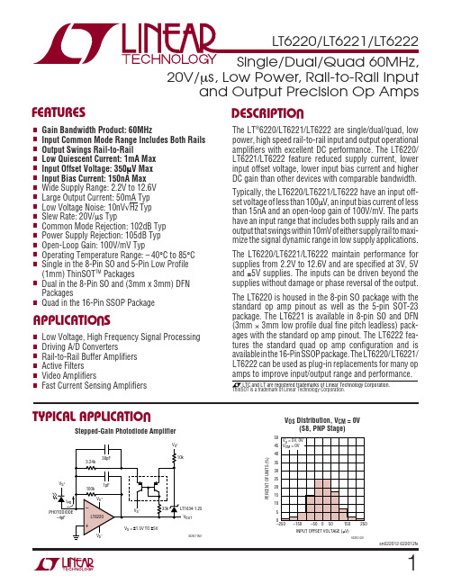
12ELECTRICAL CHARACTERISTICST A = 25°C, V S = 5V, 0V; V S = 3V, 0V; V CM = V OUT = half supply, unless otherwise notedSYMBOL PARAMETER CONDITIONS MIN TYP MAX UNITS V OS Input Offset Voltage V CM = 0V70350µVV CM = 0V (DD Package)150700µVV CM = 0V (S5 Package)200850µVV CM = V S0.5 2.5mVV CM = V S (S5 Package)0.53mV ∆V OS Input Offset Voltage Shift V S = 5V, V CM = 0V to 3.5V30195µVV S = 3V, V CM = 0V to 1.5V15120µV Input Offset Voltage Match (Channel-to-Channel)V CM = 0V100600µV (Note 9)V CM = 0V (DD Package)1501100µV I B Input Bias Current V CM = 1V15150nAV CM = V S250600nA Input Bias Current Match (Channel-to-Channel)V CM = 1V15175nA (Note 9)V CM = V S20250nA I OS Input Offset Current V CM = 1V15100nAV CM = V S15100nA Input Noise Voltage0.1Hz to 10Hz0.5µV P-P e n Input Noise Voltage Density f = 10kHz10nV/√Hz i n Input Noise Current Density f = 10kHz0.8pA/√Hz C IN Input Capacitance2pF A VOL Large Signal Voltage Gain V S = 5V, V O = 0.5V to 4.5V, R L = 1k at V S/235100V/mVV S = 5V, V O = 1V to 4V, R L = 100Ω at V S/2 3.510V/mVV S = 3V, V O = 0.5V to 2.5V, R L = 1k at V S/23090V/mV CMRR Common Mode Rejection Ratio V S = 5V, V CM = 0V to 3.5V85102dBV S = 3V, V CM = 0V to 1.5V82102dB CMRR Match (Channel-to-Channel) (Note 9)V S = 5V, V CM = 0V to 3.5V79100dBV S = 3V, V CM = 0V to 1.5V76100dB Input Common Mode Range0V S V PSRR Power Supply Rejection Ratio V S = 2.5V to 10V, V CM = 0V84105dB PSRR Match (Channel-to-Channel) (Note 9)79105dB Minimum Supply Voltage (Note 6) 2.2 2.5V V OL Output Voltage Swing LOW (Note 7)No Load540mVI SINK = 5mA100200mVI SINK = 20mA325650mV V OH Output Voltage Swing HIGH (Note 7)No Load540mVI SOURCE = 5mA130250mVI SOURCE = 20mA475900mV I SC Short-Circuit Current V S = 5V2045mAV S = 3V2035mA I S Supply Current Per Amplifier0.91mA GBW Gain-Bandwidth Product V S = 5V, Frequency = 1MHz3560MHz SR Slew Rate V S = 5V, A V = –1, R L= 1k, V O = 4V1020V/µs FPBW Full Power Bandwidth V S = 5V, A V = 1, V O = 4V p-p 1.6MHz HD Harmonic Distortion V S = 5V, A V = 1, R L= 1k, V O = 2V P-P, f C = 500kHz–77.5dBc t S Settling Time0.01%, V S = 5V, V STEP = 2V, A V = 1, R L= 1k 300ns ∆G Differential Gain (NTSC)V S = 5V, A V = 2, R L= 1k0.3%∆θDifferential Phase (NTSC)V S = 5V, A V = 2, R L= 1k0.3Degsn622012 622012fs34sn622012 622012fsSYMBOL PARAMETER CONDITIONS MIN TYP MAX UNITS V OSInput Offset VoltageV CM = 0V●90500µV V CM = 0V (DD Package)●180850µV V CM = 0V (S5 Package)●2301250µV V CM = V S●0.53mV V CM = V S (S5 Package)●0.5 3.5mV ∆V OSInput Offset Voltage ShiftV S = 5V, V CM = 0V to 3.5V ●30280µV V S = 3V, V CM = 0V to 1.5V●15190µV Input Offset Voltage Match (Channel-to-Channel)V CM = 0V ●110850µV (Note 9)V CM = 0V (DD Package)●1801400µV V OS TC Input Offset Voltage Drift (Note 8)● 1.55µV/°C (S5 Package)● 3.510µV/°C I BInput Bias CurrentV CM = 1V●20175nA V CM = V S – 0.2V ●275800nA Input Bias Current Match (Channel-to-Channel)V CM = 1V●15200nA (Note 9)V CM = V S – 0.2V ●20300nA I OS Input Offset Current V CM = 1V●15125nA V CM = V S – 0.2V●15125nA A VOLLarge Signal Voltage GainV S = 5V, V O = 0.5V to 4.5V, R L = 1k at V S /2●3090V/mV V S = 5V, V O = 1V to 4V, R L = 100Ω at V S /2●39V/mV V S = 3V, V O = 0.5V to 2.5V, R L = 1k at V S /2●2580V/mV CMRR Common Mode Rejection RatioV S = 5V, V CM = 0V to 3.5V ●82100dB V S = 3V, V CM = 0V to 1.5V ●78100dB CMRR Match (Channel-to-Channel) (Note 9)V S = 5V, V CM = 0V to 3.5V ●77100dB V S = 3V, V CM = 0V to 1.5V ●73100dBInput Common Mode Range●0V SV PSRR Power Supply Rejection RatioV S = 2.5V to 10V, V CM = 0V●81104dB PSRR Match (Channel-to-Channel) (Note 9)●76104dB Minimum Supply Voltage (Note 6)●2.2 2.5V V OLOutput Voltage Swing LOW (Note 7)No Load ●850mV I SINK = 5mA ●110220mV I SINK = 20mA ●375750mV V OHOutput Voltage Swing HIGH (Note 7)No Load●850mV I SOURCE = 5mA ●150300mV I SOURCE = 20mA ●6001100mV I SC Short-Circuit Current V S = 5V ●2040mA V S = 3V●2030mAI S Supply Current Per Amplifier ●1 1.4mA GBW Gain-Bandwidth Product V S = 5V, Frequency = 1MHz ●3060MHz SRSlew RateV S = 5V, A V = –1, R L = 1k, V O = 4V P-P●918V/µsELECTRICAL CHARACTERISTICSThe ● denotes the specifications which apply over the 0°C ≤ T A ≤ 70°Ctemperature range. V S = 5V, 0V; V S = 3V, 0V; V CM = V OUT = half supply, unless otherwise noted.5sn622012 622012fsSYMBOL PARAMETER CONDITIONS MIN TYP MAX UNITS V OSInput Offset VoltageV CM = 0V●125700µV V CM = 0V (DD Package)●3001300µV V CM = 0V (S5 Package)●3502000µV V CM = V S●0.75 3.5mV V CM = V S (S5 Package)●1 4.5mV ∆V OSInput Offset Voltage ShiftV S = 5V, V CM = 0V to 3.5V ●30300µV V S = 3V, V CM = 0V to 1.5V●30210µV Input Offset Voltage Match (Channel-to-Channel)V CM = 0V ●1751200µV (Note 9)V CM = 0V (DD Package)●3002200µV V OS TC Input Offset Voltage Drift (Note 8)● 1.57.5µV/°C (S5 Package)● 3.515µV/°C I BInput Bias CurrentV CM = 1V●25200nA V CM = V S – 0.2V ●300900nA Input Bias Current Match (Channel-to-Channel)V CM = 1V●15250nA (Note 9)V CM = V S – 0.2V ●20350nA I OS Input Offset Current V CM = 1V●20150nA V CM = V S – 0.2V●20150nA A VOLLarge Signal Voltage GainV S = 5V, V O = 0.5V to 4.5V, R L = 1k at V S /2●2570V/mV V S = 5V, V O = 1.5V to 3.5V, R L = 100Ω at V S /2● 2.58V/mV V S = 3V, V O = 0.5V to 2.5V, R L = 1k at V S /2●2060V/mV CMRR Common Mode Rejection RatioV S = 5V, V CM = 0V to 3.5V ●81100dB V S = 3V, V CM = 0V to 1.5V ●77100dB CMRR Match (Channel-to-Channel) (Note 9)V S = 5V, V CM = 0V to 3.5V ●76100dB V S = 3V, V CM = 0V to 1.5V ●72100dBInput Common Mode Range●0V SV PSRR Power Supply Rejection RatioV S = 2.5V to 10V, V CM = 0V●79104dB PSRR Match (Channel-to-Channel) (Note 9)●74104dB Minimum Supply Voltage (Note 6)●2.2 2.5V V OLOutput Voltage Swing LOW (Note 7)No Load ●1060mV I SINK = 5mA ●120240mV I SINK = 10mA ●220450mV V OHOutput Voltage Swing HIGH (Note 7)No Load●1060mV I SOURCE = 5mA ●160325mV I SOURCE = 10mA ●325650mV I SC Short-Circuit Current V S = 5V ●12.530mA V S = 3V●12.525mAI S Supply Current Per Amplifier ● 1.1 1.5mA GBW Gain-Bandwidth Product V S = 5V, Frequency = 1MHz ●2550MHz SRSlew RateV S = 5V, A V = –1, R L = 1k, V O = 4V●815V/µsELECTRICAL CHARACTERISTICSThe ● denotes the specifications which apply over the –40°C ≤ T A ≤ 85°Ctemperature range. V S = 5V, 0V; V S = 3V, 0V; V CM = V OUT = half supply unless otherwise noted. (Note 5)ELECTRICAL CHARACTERISTICST A = 25°C, V S = ±5V, V CM = 0V, V OUT = 0V, unless otherwise noted.SYMBOL PARAMETER CONDITIONS MIN TYP MAX UNITS V OS Input Offset Voltage V CM = –5V80500µVV CM = –5V (DD Package)150750µVV CM = –5V (S5 Package)200900µVV CM = 5V0.7 2.5mVV CM = 5V (S5 Package)0.73mV ∆V OS Input Offset Voltage Shift V CM = –5V to 3.5V70675µV Input Offset Voltage Match (Channel-to-Channel)V CM = –5V100850µVV CM = –5V (DD Package)1501300µV I B Input Bias Current V CM = –4V20150nAV CM = 5V250700nA Input Bias Current Match (Channel-to-Channel)V CM = –4V15175nAV CM = 5V20250nA I OS Input Offset Current V CM = –4V15100nAV CM = 5V15100nA Input Noise Voltage0.1Hz to 10Hz0.5µV P-P e n Input Noise Voltage Density f = 10kHz10nV/√Hz i n Input Noise Current Density f = 10kHz0.8pA/√Hz C IN Input Capacitance f = 100kHz2pF A VOL Large Signal Voltage Gain V O = –4V to 4V, R L = 1k3595V/mVV O = –2V to 2V, R L = 100Ω 3.510V/mV CMRR Common Mode Rejection Ratio V CM = –5V to 3.5V82102dB CMRR Match (Channel-to-Channel)77100dB Input Common Mode Range V S–V S+V PSRR Power Supply Rejection Ratio V S+ = 2.5V to 10V, V S–= 0V, V CM = 0V84105dB PSRR Match (Channel-to-Channel)79105dB V OL Output Voltage Swing LOW (Note 7)No Load540mVI SINK = 5mA100200mVI SINK = 20mA325650mV V OH Output Voltage Swing HIGH (Note 7)No Load540mVI SOURCE = 5mA130250mVI SOURCE = 20mA475900mV I SC Short-Circuit Current2550mA I S Supply Current Per Amplifier1 1.5mA GBW Gain-Bandwidth Product Frequency = 1MHz60MHz SR Slew Rate A V = –1, R L = 1k, V O = ±4V,20V/µsMeasure at V O = ±2VFPBW Full Power Bandwidth V O = 8V P-P0.8MHz HD Harmonic Distortion A V = 1, R L= 1k, V O = 2V p-p, f c = 500kHz–77.5dBc t S Settling Time0.01%, V STEP = 5V, A V = 1, R L = 1k375ns ∆G Differential Gain (NTSC)A V = 2, R L = 1k0.15%∆θDifferential Phase (NTSC)A V = 2, R L = 1k0.6Deg6sn622012 622012fs7sn622012 622012fsSYMBOL PARAMETER CONDITIONSMIN TYP MAX UNITS V OSInput Offset VoltageV CM = –5V●100650µV V CM = –5V (DD Package)●180900µV V CM = –5V (S5 Package)●2301300µV V CM = 5V●0.753mV V CM = 5V (S5 Package)●0.75 3.5mV ∆V OSInput Offset Voltage ShiftV CM = –5V to 3.5V●90850µV Input Offset Voltage Match (Channel-to-Channel)V CM = –5V ●901100µV (Note 9)V CM = –5V (DD Package)●1801500µV V OS TC Input Offset Voltage Drift (Note 8)● 1.55µV/°C (S5 Package)● 3.510µV/°C I BInput Bias CurrentV CM = –4V ●20175nA V CM = 4.8V ●275800nA Input Bias Current Match (Channel-to-Channel)V CM = –4V ●15200nA (Note 9)V CM = 4.8V ●20300nA I OS Input Offset Current V CM = –4V ●15125nA V CM = 4.8V●15125nA A VOL Large Signal Voltage Gain V O = –4V to 4V, R L = 1k ●3090V/mV V O = –2V to 2V, R L =100Ω●39V/mV CMRRCommon Mode Rejection RatioV CM = –5V to 3.5V●80100dB CMRR Match (Channel-to-Channel) (Note 9)●75100dBInput Common Mode Range●V S –V S +V PSRR Power Supply Rejection RatioV S + = 2.5V to 10V, V S –= 0V, V CM = 0V●81104dB PSRR Match (Channel-to-Channel) (Note 9)●76104dB V OLOutput Voltage Swing LOW (Note 7)No Load ●850mV I SINK = 5mA ●110220mV I SINK = 20mA ●375750mV V OHOutput Voltage Swing HIGH (Note 7)No Load●850mV I SOURCE = 5mA ●150300mV I SOURCE = 20mA ●6001100mV I SC Short-Circuit Current ●2040mA I S Supply Current Per Amplifier ●1.22mA GBW Gain-Bandwidth Product Frequency = 1MHz ●60MHz SRSlew RateA V = –1, R L = 1k , V O = ±4V,●18V/µsMeasure at V O = ±2VELECTRICAL CHARACTERISTICSThe ● denotes the specifications which apply over the 0°C ≤ T A ≤ 70°Ctemperature range. V S = ±5V, V CM = 0V, V OUT = 0V, unless otherwise noted.SYMBOL PARAMETER CONDITIONS MIN TYP MAX UNITS V OS Input Offset Voltage V CM = –5V●150800µVV CM = –5V (DD Package)●3001300µVV CM = –5V (S5 Package)●3502000µVV CM = 5V●0.75 3.5mVV CM = 5V (S5 Package)●1 4.5mV ∆V OS Input Offset Voltage Shift V CM = – 5V to 3.5V●90950µV Input Offset Voltage Match (Channel-to-Channel)V CM = –5V●1751350µV (Note 9)V CM = –5V (DD Package)●3002200µV V OS TC Input Offset Voltage Drift (Note 8)● 1.57.5µV/°C(S5 Package)● 3.515µV/°C I B Input Bias Current V CM = –4V●25200nAV CM = 4.8V●300900nA Input Bias Current Match (Channel-to-Channel)V CM = –4V●15250nA (Note 9)V CM = 4.8V●20350nA I OS Input Offset Current V CM = –4V●20150nAV CM = 4.8V●20150nA A VOL Large Signal Voltage Gain V O = –4V to 4V, R L = 1k●2570V/mVV O = –1V to 1V, R L = 100Ω● 2.58V/mV CMRR Common Mode Rejection Ratio V CM = –5V to 3.5V●79100dB CMRR Match (Channel-to-Channel) (Note 9)●74100dB Input Common Mode Range●–5 5V PSRR Power Supply Rejection Ratio V S+= 2.5V to 10V, V S– = 0V, V CM = 0V●79104dB PSRR Match (Channel-to-Channel) (Note 9)●74104dB V OL Output Voltage Swing LOW (Note 7)No Load●1060mVI SINK = 5mA●120240mVI SINK = 10mA●220450mV V OH Output Voltage Swing HIGH (Note 7)No Load●1060mVI SOURCE = 5mA●160325mVI SOURCE = 10mA●325650mV I SC Short-Circuit Current●12.530mA I S Supply Current● 1.4 2.25mA GBW Gain-Bandwidth Product Frequency = 1MHz●50MHz SR Slew Rate A V = –1, R L = 1k,V O = ±4V,●15V/µsMeasure at V O = ±2VNote 1: Absolute Maximum Ratings are those values beyond which the life of a device may be impaired.Note 2: The inputs are protected by back-to-back diodes. If the differential input voltage exceeds 1.4V, the input current should be limited to less than 10mA.Note 3: A heat sink may be required to keep the junction temperature below the absolute maximum rating when the output is shorted indefinitely.Note 4: The LT6220C/LT6221C/LT6222C and LT6220I/LT6221I/LT6222I are guaranteed functional over the temperature range of –40°C and 85°C. Note 5: The LT6220C/LT6221C/LT6222C are guaranteed to meet specified performance from 0°C to 70°C. The LT6220C/LT6221C/LT6222C are designed, characterized and expected to meet specified performance from –40°C to 85°C but is not tested or QA sampled at these temperatures. The LT6220I/LT6221I/LT6222I are guaranteed to meet specified performance from –40°C to 85°C.Note 6: Minimum supply voltage is guaranteed by power supply rejection ratio test.Note 7: Output voltage swings are measured between the output and power supply rails.Note 8: This parameter is not 100% tested.Note 9: Matching parameters are the difference between amplifiers A and D and between B and C on the LT6222; between the two amplifiers on the LT6221.Note 10: Thermal resistance (θJA) varies with the amount of PC board metal connected to the package. The specified values are for short traces connected to the leads. If desired, the thermal resistance can be substantially reduced by connecting Pin 2 of the LT6220CS5/LT6220IS5 or the underside metal of DD packages to a larger metal area (V S– trace).ELECTRICAL CHARACTERISTICS The ● denotes the specifications which apply over the –40°C ≤ TA≤ 85°C temperature range. V S = ±5V, V CM = 0V, V OUT = 0V, unless otherwise noted. (Note 5)8sn622012 622012fs91011TIME (SECONDS)8622012 G202461071359V S = 5V, 0VV S = ±5V PHASEGain and Phase vs FrequencyV S = 5V, 0V100ns/DIV622012 G36A V = 1R L = 1k121314sn622012 622012fsA pair of complementary common emitter stages Q14/Q15that enable the output to swing from rail-to-rail construct the output stage. The capacitors C2 and C3 form the local feedback loops that lower the output impedance at high frequency. These devices are fabricated by Linear Technology’s proprietary high speed complementary bi-polar process.Power DissipationThe LT6222, with four amplifiers, is housed in a small 16-lead SSOP package and typically has a thermal resis-tance (θJA ) of 135°C/W. It is necessary to ensure that the die’s junction temperature does not exceed 150°C. The junction temperature, T J , is calculated from the ambient temperature, T A , power dissipation, P D , and thermal resis-tance, θJA :T J = T A + (P D • θJA )The power dissipation in the IC is the function of the supply voltage, output voltage and the load resistance. For a given supply voltage, the worst-case power dissipation P D(MAX)occurs when the maximum supply current and the output voltage is at half of either supply voltage for a given load resistance. P D(MAX) is given by:P V I V R D MAX S S MAX S L ()()•/=()+⎛⎝⎜⎞⎠⎟22Example: F or an LT6222 in a 16-lead SSOP package operating on ±5V supplies and driving a 100Ω load, the worst-case power dissipation is given by:P Amp mA mWD MAX ()/•../...=()+()=+=1018251000018006258052If all four amplifiers are loaded simultaneously, then the total power dissipation is 322mW.The maximum ambient temperature at which the part is allowed to operate is:T A = T J – (P D(MAX) • 135°C/W)= 150°C – (0.322W • 135°C/W) = 106.5°CAPPLICATIO S I FOR ATIOW UUU Input Offset VoltageThe offset voltage will change depending upon which input stage is active. The PNP input stage is active from the negative supply rail to 1.2V below the positive supply rail,then the NPN input stage is activated for the remaining input range up to the positive supply rail during which the PNP stage remains inactive. The offset voltage is typically less than 70µV in the range that the PNP input stage is active.Input Bias CurrentThe LT6220/LT6221/LT6222 employ a patent pending technique to trim the input bias current to less than 150nA for the input common mode voltage of 0.2V above the negative supply rail to 1.2V below the positive rail. The low input offset voltage and low input bias current of the LT6220/LT6221/LT6222 provide precision performance especially for high source impedance applications.OutputThe LT6220/LT6221/LT6222 can deliver a large output current, so the short-circuit current limit is set around 50mA to prevent damage to the device. Attention must be paid to keep the junction temperature of the IC below the absolute maximum rating of 150°C (refer to the Power Dissipation section) when the output is in continuous short circuit. The output of the amplifier has reverse-biased diodes connected to each supply. If the output is forced beyond either supply, unlimited current will flow through these diodes. If the current is transient and limited to several hundred milliamperes, no damage will occur to the device.Overdrive ProtectionWhen the input voltage exceeds the power supplies, two pair of crossing diodes, D1 to D4, will prevent the output from reversing polarity. If the input voltage exceeds either power supply by 700mV, diode D1/D2 or D3/D4 will turn on to keep the output at the proper polarity. For the phase reversal protection to perform properly, the input current must be limited to less than 5mA. If the amplifier is155µs/DIV622012 F03Figure 3. Stepped-Gain Photodiode Amplifier Response Single 3V Supply, 1MHz, 4th Order Butterworth Filter161718Information furnished by Linear Technology Corporation is believed to be accurate and reliable. However, no responsibility is assumed for its use. Linear Technology Corporation makes no represen-tation that the interconnection of its circuits as described herein will not infringe on existing patent rights.1920Linear Technology Corporation1630 McCarthy Blvd., Milpitas, CA 95035-7417(408) 432-1900 ● F AX: (408) 434-0507 ● © LINEAR TECHNOLOGY CORPORA TION 2003LT/TP 0204 1K • PRINTED IN USA。
TLE2161AMFK中文资料
IMPORTANT NOTICETexas Instruments and its subsidiaries (TI) reserve the right to make changes to their products or to discontinue any product or service without notice, and advise customers to obtain the latest version of relevant information to verify, before placing orders, that information being relied on is current and complete. All products are sold subject to the terms and conditions of sale supplied at the time of order acknowledgement, including those pertaining to warranty, patent infringement, and limitation of liability.TI warrants performance of its semiconductor products to the specifications applicable at the time of sale in accordance with TI’s standard warranty. Testing and other quality control techniques are utilized to the extent TI deems necessary to support this warranty. Specific testing of all parameters of each device is not necessarily performed, except those mandated by government requirements.CERTAIN APPLICATIONS USING SEMICONDUCTOR PRODUCTS MAY INVOLVE POTENTIAL RISKS OF DEATH, PERSONAL INJURY, OR SEVERE PROPERTY OR ENVIRONMENTAL DAMAGE (“CRITICAL APPLICATIONS”). TI SEMICONDUCTOR PRODUCTS ARE NOT DESIGNED, AUTHORIZED, OR WARRANTED TO BE SUITABLE FOR USE IN LIFE-SUPPORT DEVICES OR SYSTEMS OR OTHER CRITICAL APPLICATIONS. INCLUSION OF TI PRODUCTS IN SUCH APPLICATIONS IS UNDERSTOOD TO BE FULLY AT THE CUSTOMER’S RISK.In order to minimize risks associated with the customer’s applications, adequate design and operating safeguards must be provided by the customer to minimize inherent or procedural hazards.TI assumes no liability for applications assistance or customer product design. TI does not warrant or represent that any license, either express or implied, is granted under any patent right, copyright, mask work right, or other intellectual property right of TI covering or relating to any combination, machine, or process in which such semiconductor products or services might be or are used. TI’s publication of information regarding any third party’s products or services does not constitute TI’s approval, warranty or endorsement thereof.Copyright © 1998, Texas Instruments Incorporated。
英隨頓公司PL6型号微型电路保护器产品说明说明书

SG62211Description• H igh-quality miniature circuit breakers for commercial and residential applications • Contact position indicator red - green• Guide for secure terminal connection• 3-position DIN rail clip, permits removal from existing busbar system• C omprehensive range of accessories can be mounted subsequently• Rated currents up to 63 A• Tripping characteristics B, C, D• R ated breaking capacity 6 kA according to IEC/EN 60898-1Rated current I n (A)TypeDesignationArticle No.Units perpackage6 kA, Characteristic BSG454111PL6-B1/116474012/1201.5PL6-B1,5/116473612/1201.6PL6-B1,6/116473712/1202PL6-B2/128651612/1202.5PL6-B2,5/116474112/1203PL6-B3/116474312/1203.5PL6-B3,5/116474212/1204PL6-B4/128651712/1205PL6-B5/116474412/1206PL6-B6/128651812/1208PL6-B8/116474512/12010PL6-B10/128651912/12012PL6-B12/116473812/12013PL6-B13/128652012/12015PL6-B15/116473912/12016PL6-B16/128652112/12020PL6-B20/128652212/12025PL6-B25/128652312/12032PL6-B32/128652412/12040PL6-B40/128652512/12050PL6-B50/128652612/12063PL6-B63/128652712/1201-poleSG514111PL6-B1/1N1649038/801.5PL6-B1,5/1N1649018/801.6PL6-B1,6/1N1649028/802PL6-B2/1N1649078/802.5PL6-B2,5/1N1649068/803PL6-B3/1N1649118/803.5PL6-B3,5/1N1649108/804PL6-B4/1N1649138/805PL6-B5/1N1649148/806PL6-B6/1N1060258/808PL6-B8/1N1649158/8010PL6-B10/1N1060268/8012PL6-B12/1N1649048/8013PL6-B13/1N1060278/8015PL6-B15/1N1649058/8016PL6-B16/1N1060288/8020PL6-B20/1N1649088/8025PL6-B25/1N1649098/8032PL6-B32/1N1649128/801+N-poleRated current I n (A)TypeDesignationArticle No.Units perpackage SG515111PL6-B1/21648036/601.5PL6-B1,5/21648016/601.6PL6-B1,6/21648026/602PL6-B2/22865506/602.5PL6-B2,5/21648066/603PL6-B3/21648086/603.5PL6-B3,5/21648076/604PL6-B4/22865516/605PL6-B5/21648096/606PL6-B6/22865526/608PL6-B8/21648106/6010PL6-B10/22865536/6012PL6-B12/21648046/6013PL6-B13/22865546/6015PL6-B15/21648056/6016PL6-B16/22865556/6020PL6-B20/22865566/6025PL6-B25/22865576/6032PL6-B32/22865586/6040PL6-B40/22865596/6050PL6-B50/22865606/6063PL6-B63/22865616/602-poleSG622111PL6-B1/31648684/401.5PL6-B1,5/31648664/401.6PL6-B1,6/31648674/402PL6-B2/32865844/402.5PL6-B2,5/31648714/403PL6-B3/31648734/403.5PL6-B3,5/31648724/404PL6-B4/32865854/405PL6-B5/31648744/406PL6-B6/32865864/408PL6-B8/31648754/4010PL6-B10/32865874/4012PL6-B12/31648694/4013PL6-B13/32865884/4015PL6-B15/31648704/4016PL6-B16/32865894/4020PL6-B20/32865904/4025PL6-B25/32865914/4032PL6-B32/32865924/4040PL6-B40/32865934/4050PL6-B50/32865944/4063PL6-B63/32865954/403-poleRated current I n (A)TypeDesignationArticle No.Units perpackage SG647111PL6-B1/3N1650023/301.5PL6-B1,5/3N1650003/301.6PL6-B1,6/3N1650013/302PL6-B2/3N1650073/302.5PL6-B2,5/3N1650063/303PL6-B3/3N1650093/303.5PL6-B3,5/3N1650083/304PL6-B4/3N1650103/305PL6-B5/3N1650113/306PL6-B6/3N1060353/308PL6-B8/3N1650123/3010PL6-B10/3N1060363/3012PL6-B12/3N1650033/3013PL6-B13/3N1650043/3015PL6-B15/3N1650053/3016PL6-B16/3N1060373/3020PL6-B20/3N1060383/3025PL6-B25/3N1060393/3032PL6-B32/3N1060403/3040PL6-B40/3N1060413/3050PL6-B50/3N1069033/3063PL6-B63/3N1069043/303+N-poleSG266121PL6-B1/41664893/301.5PL6-B1,5/41664873/301.6PL6-B1,6/41664883/302PL6-B2/41664963/302.5PL6-B2,5/41664953/303PL6-B3/41664993/304PL6-B4/41665013/305PL6-B5/41665033/306PL6-B6/41665053/308PL6-B8/41665073/3010PL6-B10/41664903/3012PL6-B12/41664913/3013PL6-B13/41664923/3015PL6-B15/41664933/3016PL6-B16/41664943/3020PL6-B20/41664973/3025PL6-B25/41664983/3032PL6-B32/41665003/3040PL6-B40/41665023/3050PL6-B50/41665043/3063PL6-B63/41665063/304-poleRated current I n (A)TypeDesignationArticle No.Units perpackage6 kA, Characteristic CSG454110.16PL6-C0.16/116474612/1200.25PL6-C0,25/116474712/1200.5PL6-C0,5/116474812/1200.75PL6-C0,75/116474912/1201PL6-C1/116475412/1201.5PL6-C1,5/116475012/1201.6PL6-C1,6/116475112/1202PL6-C2/128652812/1202.5PL6-C2,5/116475512/1203PL6-C3/116475712/1203.5PL6-C3,5/116475612/1204PL6-C4/128652912/1205PL6-C5/116475812/1206PL6-C6/128653012/1208PL6-C8/116475912/12010PL6-C10/128653112/12012PL6-C12/116475212/12013PL6-C13/128653212/12015PL6-C15/116475312/12016PL6-C16/128653312/12020PL6-C20/128653412/12025PL6-C25/128653512/12032PL6-C32/128653612/12040PL6-C40/128653712/12050PL6-C50/128653812/12063PL6-C63/128653912/1201-poleSG514110.16PL6-C0.16/1N1649168/800.25PL6-C0,25/1N1649178/800.5PL6-C0,5/1N1649188/800.75PL6-C0,75/1N1649198/801PL6-C1/1N1649228/801.5PL6-C1,5/1N1649208/801.6PL6-C1,6/1N1649218/802PL6-C2/1N1060298/802.5PL6-C2,5/1N1649258/803PL6-C3/1N1649298/803.5PL6-C3,5/1N1649288/804PL6-C4/1N1060308/805PL6-C5/1N1649318/806PL6-C6/1N1060318/808PL6-C8/1N1649328/8010PL6-C10/1N1060328/8012PL6-C12/1N1649238/8013PL6-C13/1N1060338/8015PL6-C15/1N1649248/8016PL6-C16/1N1060348/8020PL6-C20/1N1649268/8025PL6-C25/1N1649278/8032PL6-C32/1N1649308/801+N-poleRated current I n (A)TypeDesignationArticle No.Units perpackage SG515110.16PL6-C0.16/21648116/600.25PL6-C0,25/21648126/600.5PL6-C0,5/21648136/600.75PL6-C0,75/21648146/601PL6-C1/21648176/601.5PL6-C1,5/21648156/601.6PL6-C1,6/21648166/602PL6-C2/22865626/602.5PL6-C2,5/21648206/603PL6-C3/21648226/603.5PL6-C3,5/21648216/604PL6-C4/22865636/605PL6-C5/21648236/606PL6-C6/22865646/608PL6-C8/21648246/6010PL6-C10/22865656/6012PL6-C12/21648186/6013PL6-C13/22865666/6015PL6-C15/21648196/6016PL6-C16/22865676/6020PL6-C20/22865686/6025PL6-C25/22865696/6032PL6-C32/22865706/6040PL6-C40/22865716/6050PL6-C50/22865726/6063PL6-C63/22865736/602-poleSG622110.16PL6-C0.16/31648764/400.25PL6-C0,25/31648774/400.5PL6-C0,5/31648784/400.75PL6-C0,75/31648794/401PL6-C1/31648824/401.5PL6-C1,5/31648804/401.6PL6-C1,6/31648814/402PL6-C2/32865964/402.5PL6-C2,5/31648854/403PL6-C3/31648874/403.5PL6-C3,5/31648864/404PL6-C4/32865974/405PL6-C5/31648884/406PL6-C6/32865984/408PL6-C8/31648894/4010PL6-C10/32865994/4012PL6-C12/31648834/4013PL6-C13/32866004/4015PL6-C15/31648844/4016PL6-C16/32866014/4020PL6-C20/32866024/4025PL6-C25/32866034/4032PL6-C32/32866044/4040PL6-C40/32866054/4050PL6-C50/32866064/4063PL6-C63/32866074/403-poleRated current I n (A)TypeDesignationArticle No.Units perpackage SG647110.16PL6-C0.16/3N1650133/300.25PL6-C0,25/3N1650143/300.5PL6-C0,5/3N1650153/300.75PL6-C0,75/3N1650163/301PL6-C1/3N1650193/301.5PL6-C1,5/3N1650173/301.6PL6-C1,6/3N1650183/302PL6-C2/3N1069053/302.5PL6-C2,5/3N1650223/303PL6-C3/3N1650243/303.5PL6-C3,5/3N1650233/304PL6-C4/3N1069063/305PL6-C5/3N1650253/306PL6-C6/3N1069073/308PL6-C8/3N1650263/3010PL6-C10/3N1069083/3012PL6-C12/3N1650203/3013PL6-C13/3N1069093/3015PL6-C15/3N1650213/3016PL6-C16/3N1069103/3020PL6-C20/3N1069113/3025PL6-C25/3N1069123/3032PL6-C32/3N1069133/3040PL6-C40/3N1069143/3050PL6-C50/3N1069153/3063PL6-C63/3N1069163/303+N-poleSG266120.16PL6-C0.16/41665083/300.25PL6-C0,25/41665093/300.5PL6-C0,5/41665103/300.75PL6-C0,75/41665113/301PL6-C1/41665143/301.5PL6-C1,5/41665123/301.6PL6-C1,6/41665133/302PL6-C2/41665213/302.5PL6-C2,5/41665203/303PL6-C3/41665253/303.5PL6-C3,5/41665243/304PL6-C4/41665273/305PL6-C5/41665293/306PL6-C6/41665313/308PL6-C8/41665333/3010PL6-C10/41665153/3012PL6-C12/41665163/3013PL6-C13/41665173/3015PL6-C15/41665183/3016PL6-C16/41665193/3020PL6-C20/41665223/3025PL6-C25/41665233/3032PL6-C32/41665263/3040PL6-C40/41665283/3050PL6-C50/41665303/3063PL6-C63/41665323/304-poleRated current I n (A)TypeDesignationArticle No.Units perpackage6 kA, Characteristic DSG454110.5PL6-D0,5/116476012/1201PL6-D1/116476512/1201.5PL6-D1,5/116476112/1201.6PL6-D1,6/116476212/1202PL6-D2/128654012/1202.5PL6-D2,5/116476612/1203PL6-D3/116476812/1203.5PL6-D3,5/116476712/1204PL6-D4/128654112/1205PL6-D5/116476912/1206PL6-D6/128654212/1208PL6-D8/116477012/12010PL6-D10/128654312/12012PL6-D12/116476312/12013PL6-D13/128654412/12015PL6-D15/116476412/12016PL6-D16/128654512/12020PL6-D20/128654612/12025PL6-D25/128654712/12032PL6-D32/128654812/12040PL6-D40/128654912/1201-poleSG514110.5PL6-D0,5/1N1649338/801PL6-D1/1N1649368/801.5PL6-D1,5/1N1649348/801.6PL6-D1,6/1N1649358/802PL6-D2/1N1649438/802.5PL6-D2,5/1N1649428/803PL6-D3/1N1649478/803.5PL6-D3,5/1N1649468/804PL6-D4/1N1649488/805PL6-D5/1N1649498/806PL6-D6/1N1649508/808PL6-D8/1N1649518/8010PL6-D10/1N1649378/8012PL6-D12/1N1649388/8013PL6-D13/1N1649398/8015PL6-D15/1N1649408/8016PL6-D16/1N1649418/8020PL6-D20/1N1649448/8025PL6-D25/1N1649458/801+N-poleRated current I n (A)TypeDesignationArticle No.Units perpackage SG515110.5PL6-D0,5/21648256/601PL6-D1/21648286/601.5PL6-D1,5/21648266/601.6PL6-D1,6/21648276/602PL6-D2/22865746/602.5PL6-D2,5/21648316/603PL6-D3/21648336/603.5PL6-D3,5/21648326/604PL6-D4/22865756/605PL6-D5/21648346/606PL6-D6/22865766/608PL6-D8/21648356/6010PL6-D10/22865776/6012PL6-D12/21648296/6013PL6-D13/22865786/6015PL6-D15/21648306/6016PL6-D16/22865796/6020PL6-D20/22865806/6025PL6-D25/22865816/6032PL6-D32/22865826/6040PL6-D40/22865836/602-poleSG622110.5PL6-D0,5/31648904/401PL6-D1/31648934/401.5PL6-D1,5/31648914/401.6PL6-D1,6/31648924/402PL6-D2/32866084/402.5PL6-D2,5/31648964/403PL6-D3/31648984/403.5PL6-D3,5/31648974/404PL6-D4/32866094/405PL6-D5/31648994/406PL6-D6/32866104/408PL6-D8/31649004/4010PL6-D10/32866114/4012PL6-D12/31648944/4013PL6-D13/32866124/4015PL6-D15/31648954/4016PL6-D16/32866134/4020PL6-D20/32866144/4025PL6-D25/32866154/4032PL6-D32/32866164/4040PL6-D40/32866174/403-poleRated current I n (A)TypeDesignationArticle No.Units perpackage SG647110.5PL6-D0,5/3N1650273/301PL6-D1/3N1650303/301.5PL6-D1,5/3N1650283/301.6PL6-D1,6/3N1650293/302PL6-D2/3N1650373/302.5PL6-D2,5/3N1650363/303PL6-D3/3N1650413/303.5PL6-D3,5/3N1650403/304PL6-D4/3N1650433/305PL6-D5/3N1650453/306PL6-D6/3N1650463/308PL6-D8/3N1650473/3010PL6-D10/3N1650313/3012PL6-D12/3N1650323/3013PL6-D13/3N1650333/3015PL6-D15/3N1650343/3016PL6-D16/3N1650353/3020PL6-D20/3N1650383/3025PL6-D25/3N1650393/3032PL6-D32/3N1650423/3040PL6-D40/3N1650443/303+N-poleSG266120.5PL6-D0,5/41665343/301PL6-D1/41665373/301.5PL6-D1,5/41665353/301.6PL6-D1,6/41665363/302PL6-D2/41665443/302.5PL6-D2,5/41665433/303PL6-D3/41665483/303.5PL6-D3,5/41665473/304PL6-D4/41665503/305PL6-D5/41665523/306PL6-D6/41665533/308PL6-D8/41665543/3010PL6-D10/41665383/3012PL6-D12/41665393/3013PL6-D13/41665403/3015PL6-D15/41665413/3016PL6-D16/41665423/3020PL6-D20/41665453/3025PL6-D25/41665463/3032PL6-D32/41665493/3040PL6-D40/41665513/304-poleSpecifi cations | Miniature Circuit Breakers PL6Description• High selectivity between MCB and back-up fuse due to low let-throughenergy• Compatible with standard busbar• T win-purpose terminal (lift/open-mouthed) above and below• B usbar positioning optionally above or below• M eets the requirements of insulation co-ordination, distance between con-tacts ≥ 4 mm, for secure isolation• S uitable for applications up to 48 V DCAccessories:Auxiliary switch for subsequent installation ZP-IHK286052ZP-WHK286053 Tripping signal switch for subsequent installation ZP-NHK248437 Remote control and automatic switching device Z-FW/LP248296Shunt trip release ZP-ASA/..248438, 248439 Undervoltage release Z-USA/..248288-248291 Compact enclosure KLV-TC-2276240KLV-TC-4276241 Additional terminal 35 mm2Z-HA-EK/35263960 Switching interlock Z-IS/SPE-1TE274418Technical DataPL6ElectricalIEC/EN 60898-1Design according toCurrent test marks as printed onto the deviceRated voltage U n AC: 230/400 VDC: 48 V (per pole, max. 2 poles)Rated frequency50/60 HzRated breaking capacity according to IEC/EN 60898-1I cn 6 kACharacteristic B, C, DBack-up fuse max. 100 A gLSelectivity class3Rated impulse withstand voltage U imp 4 kV (1.2/50 μs)Enduranceelectrical components≥ 10,000 switching operationsmechanical components≥ 20,000 switching operationsLine voltage connection at will (above/below)Minimal voltage12 V AC/DCMechanicalFrame size45 mmDevice height80 mmDevice width17.5 mm per pole (1MU)Mounting quick fastening with 3 lock-in positions on DIN rail IEC/EN 60715 Degree of protection IP20Upper and lower terminals open mouthed/lift terminalsTerminal protection fi nger and hand touch safe, DGUV VS3, EN 50274Terminal capacity1-25 mm2Terminal torque2-2.4 NmBusbar thickness 0.8 - 2 mmMounting independent of positionConnection diagramsDimensions (mm)Tripping Characteristics (IEC/EN 60898-1)Quick-acting (B), slow (C), very slow (D)Tripping characteristic BTripping characteristic CTripping characteristic DTRIPPING CURRENTTRIPPING CURRENTTRIPPING CURRENT1-pole1+N-pole2-pole3-pole3+N-pole4-pole1P2P3P+N4P1P+N3PEffect of the Ambient Temperature on Thermal Tripping Behaviour Effect of Power FrequencyEffect of power frequency on the tripping behaviour I MA of the quick releaseLoad Capacity of Series Connected Miniature Circuit BreakersPower frequency f [Hz]162/35060100200300400I MA (f)/I MA (50 Hz) [%]91100101106115134141Adjusted rated current values according to the ambient temperatureNumber of devices (n) 1-poleLet-through Energy PL6Let-through Energy PL6, Characteristic B, 1-pole Let-through Energy PL6, Characteristic C, 1-poleLet-through Energy PL6, Characteristic D, 1-poleProspective short-circuit current [A]L e t t h r o u g h e n e r g y I 2t [A 2 s e c ]Prospective short-circuit current [A]L e t t h r o u g h e n e r g y I 2t [A 2 s e c ]Prospective short-circuit current [A]L e t t h r o u g h e n e r g y I 2t [A 2 s e c ]Short Circuit Selectivity PL6 towards DII-DIV fuse linkIn case of short circuit, there is selectivity between the miniature circuit breakers PL6 and the upstream fuses up to the specifi ed values of the selectivity limit current I s [kA] (i. e. in case of short-circuit currents I ks under I s only the MCB will trip, in case of short circuit currents above this value both protective devices will respond).*) basically in accordance with EN 60898-1 D.5.2.bShort circuit selectivity Characteristic B towards fuse link DII-DIV *)Short circuit selectivity Characteristic C towards fuse link DII-DIV *)Short circuit selectivity Characteristic D towards fuse link DII-DIV *)1) Selectivity limit current I s under 0.5 kA 2) S electivity limit current I s = rated breaking capacity I cn of the MCBDarker areas: no selectivityPL6DII-DIV gL/gG I n [A]10162025355063801002<0.51)<0.51)0.8 1.6 6.02) 6.02) 6.02) 6.02) 6.02)4<0.51)<0.51)0.6 1.0 3.6 6.02) 6.02) 6.02) 6.02)1)1)2)2)2)PL6DII-DIV gL/gG I n [A]10162025355063801002<0.51)<0.51)0.8 1.6 6.02) 6.02) 6.02) 6.02) 6.02)4<0.51)<0.51)0.60.8 1.8 3.6 6.02) 6.02) 6.02)1)1)2)2)2)PL6DII-DIV gL/gG I n [A]10162025355063801001)<0.51)0.6 1.0 2.8 5.8 6.02) 6.02) 6.02)Short Circuit Selectivity PL6 towards D01-D03 fuse linkIn case of short circuit, there is selectivity between the miniature circuit breakers PL6 and the upstream fuses up to the specifi ed values of the selectivity limit current I s [kA] (i. e. in case of short-circuit currents I ks under I s only the MCB will trip, in case of short circuit currents above this value both protective devices will respond).*) basically in accordance with EN 60898-1 D.5.2.bShort circuit selectivity Characteristic B towards fuse link D01-D03*)Short circuit selectivity Characteristic C towards fuse link D01-D03*)Short circuit selectivity Characteristic D towards fuse link D01-D03*)1) Selectivity limit current I s under 0.5 kA 2) S electivity limit current I s = rated breaking capacity I cn of the MCBDarker areas: no selectivityPL6D01-D03 gL/gG I n [A]10162025355063801002<0.51)<0.51)0.6 1.0 6.02) 6.02) 6.02) 6.02) 6.02)1)1)2)2)2)2)PL6D01-D03 gL/gG I n [A]10162025355063801002<0.51)<0.51)0.50.7 6.02) 6.02) 6.02) 6.02) 6.02)1)1)1)2)2)2)PL6D01-D03 gL/gG I n [A]10162025355063801001)<0.51)0.60.8 2.2 6.02) 6.02) 6.02) 6.02)Short Circuit Selectivity PL6 towards NH-00 fuse linkIn case of short circuit, there is selectivity between the miniature circuit breakers PL6 and the upstream fuses up to the specifi ed values of the selectivity limit current I s [kA] (i. e. in case of short-circuit currents I ks under I s only the MCB will trip, in case of short circuit currents above this value both protective devices will respond).*) basically in accordance with EN 60898-1 D.5.2.bShort circuit selectivity Characteristic B towards fuse link NH-00*)Short circuit selectivity Characteristic C towards fuse link NH-00*)Short circuit selectivity Characteristic D towards fuse link NH-00*)1) Selectivity limit current I s under 0.5 kA 2) S electivity limit current I s = rated breaking capacity I cn of the MCBDarker areas: no selectivityPL6NH-00 gL/gG I n [A]1620253235405063801001251602<0.51)0.5 1.0 2.5 6.02) 6.02) 6.02) 6.02) 6.02) 6.02) 6.02) 6.02)4<0.51)<0.51)0.8 1.3 2.3 4.3 6.02) 6.02) 6.02) 6.02) 6.02) 6.02)5<0.51)<0.51)0.7 1.1 1.6 2.2 3.6 4.8 6.02) 6.02) 6.02) 6.02)6<0.51)<0.51)0.7 1.1 1.5 2.0 3.3 4.3 6.02) 6.02) 6.02) 6.02)1)1)2)2)2)PL6NH-00 gL/gG I n [A]1620253235405063801001251602<0.51)0.6 1.0 2.5 6.02) 6.02) 6.02) 6.02) 6.02) 6.02) 6.02) 6.02)4<0.51)<0.51)0.7 1.0 1.5 2.1 3.6 5.0 6.02) 6.02) 6.02) 6.02)5<0.51)<0.51)0.60.8 1.2 1.7 2.8 3.8 6.02) 6.02) 6.02) 6.02)6<0.51)<0.51)0.50.8 1.2 1.5 2.5 3.3 5.7 6.02) 6.02) 6.02)1)1)2)2)2)PL6NH-00 gL/gG I n [A]1620253235405063801001251602<0.51)<0.51)0.8 1.3 2.1 3.1 6.02) 6.02) 6.02) 6.02) 6.02) 6.02)1)<0.51)0.71.0 1.62.23.8 5.2 6.02) 6.02) 6.02) 6.02)。
CREE XP-G (R5) LED 手持闪光灯用户手册说明书

®User ManualFeatures• CREE XP-G (R5) LED• Maximum output of up to 190 lumens• Highly effective current circuit board• High efficiency circuit enables maximum runtime of up to 27 hours • 3 presetted brightness levels• Active dimming system with auto-adjust function• Soft turn-on mode and low illumination for everyday usage• Convenient one-handed operation• Reverse polarity protection• Equipped with integrated lens• Constructed from aerospace grade aluminum alloy• Type III military grade hard anodizing• Special-made rhombic knurling for better grip• Waterproof in accordance with IPX-8 (2 meters submersible)• Tail stand abilityDimensionsLength: 64mm (2.52”)Head Diameter: 19.8mm (0.78”)Tail Diameter: 19.8mm (0.78”)Weight: 23.8g (0.85oz)(without battery)Brightness ControlWhen the flashlight is turned on from off:• Flashlight will enter high output level when the head is parallel to the floor • Flashlight will enter medium output level when the head is at 45 degreesThanks for purchasing NITECORE!NOTICEThe stated data has beenmeasured in accordance with theinternational flashlight testingstandards ANSI/NEMA FL1, usingSYSMAX CR123 battery (3V,1550mAh) under laboratoryconditions. The data may vary inreal-world use due to differentbattery usage or environmentalconditions.SYSMAX Industry Co.,Ltd.TEL: +86-20-83862000FAX: +86-20-83882723E-mail: *****************Web: Address: Rm1407-08, Glorious Tower, 850 East Dongfeng Road,Guangzhou, China 510600Brightness & Runtime6h30min27h2hHIGH MID LOWLUMENS60LUMENS190LUMENS201450cd (Peak Beam Intensity)76m (Beam Distance)IPX-8, 2m(Waterproof AND Submersible)1.5m (Impact Resistant)AccessoriesKey chain, spare O-ringPlease follow our facebook for more info: NITECORE Flashlights Operation instructionsBattery installationInsert one CR123 batteryWARNINGAlways ensure batteries are inserted with the positive (+) ends pointing towardthe flashlight head. If incorrectly installed, the flashlight will not work.ON/OFFTurn ON: Rotate the head of the flashlight in a clockwise direction to turn it on.Turn OFF: Rotate the head of the flashlight in a counter-clockwise direction toturn it off.Notes:1. Each time you turn on the flashlight, the SENS CR built-in accelerationsensor can detect the angle and switch to the appropriate brightness level2. After the lights is powered on, the sensor will shut off to avoid brightnesschanging when the user changes the flashlight angle.Active Dimming TechnologyWith the flashlight switched off, turn on the light with the head pointed straightup. The light will access the active dimming function immediately. Anacceleration sensor is built in the SENS CR flashlight, which can continuouslydetect the angle of the light and work with the light’s mico-computer to selectthe appropriate output. For example, when it detects a horizontal position, thebuilt-in micro-computer will assume a higher output is appropriate and increaseoutput to illuminate a longer distance. When it detects a vertical position,micro-computer will decrease output so to save battery life, extending runtimeof SENS up to 5-8 times.Notes:1. When the flashlight switches from low to high level, the output will increasemomentarily, allowing the user to observe distant targets.2. After the flashlight switches from low to high level, the brightness willdecrease slowly to allow the user’s eyes to adapt.MaintenanceClean the threads twice a year with a clean cloth and coat with silicone grease.Warranty ServiceAll NITECORE® products are warranted for quality. DOA / defective productscan be exchanged for replacement though a local distributor/dealer within the14 days of purchase. After 14 days, all defective / malfunctioning NITECORE®products will be repaired free of charge for a period of 18 months from the dateof purchase. After 18 months, a limited warranty applies, covering the cost oflabor and maintenance, but not the cost of accessories or replacement parts.The warranty is nullified in all of the following situations:1. The product(s) is/are broken down, reconstructed and/or modified byunauthorized parties.2. The product(s) is/are damaged through improper use.3. The product(s) is/are damaged by leakage of batteries.For the latest information on NITECORE® products and services, pleasecontact your national NITECORE® distributor or send an email to********************。
IR6216;IR6216S;中文规格书,Datasheet资料

Max. Units Test Conditions
— — — —
o
C
o
C/W
Lead Assignments
3 (Vcc) 3 (Vcc) 1 2 3 4 5 - Ground - In - Vcc - DG - Out
12345
12345
5 Lead - TO-220 IR6216 Part Number
The IR6216 is a 5 terminal monolithic HIGH SIDE SWITCH with built in short circuit, over- temperature, ESD protections, inductive load turn off capability and diagnostic feedback. The on-chip protection circuit limits the average current during short circuit if the drain current exceeds 10A. The protection circuit latches off the high side switch if the junction temperature exceeds 170oC and latches on after the junction temperature falls by 10oC. The Vcc (drain) to out (source) voltage is actively clamped at 55V, improving its performance during turn off with inductive loads. The on-chip charge pump high side driver stage is floating and referenced to the source of the Power MOSFET. Thus the logic to power ground isolation can be as high as 50V. This allows operation with larger offset as well as controlling the switch during load energy recirculation or regeneration. A diagnostic pin is provided for status feedback of short circuit, over temperature and open load detection.
XC6216_2中文资料

1
5
6
2
2
5
3
4
4
4
3
3
5
1
1
-
-
2
PIN NAME
VIN VSS NC CE VOUT NC
FUNCTIONS
Power Input Ground
No connection ON/OFF Control
Output No connection
˔XC6216C Series
SOT-25 1 2 3 4 5 -
DESCRIPTION : Fixed output voltage, High Active : Output voltage externally set, High Active : Fixed output voltage, No CE function
: For the voltage within 2.0V ~9.9V; e.g. 2.5V ˰ 25 5.0V ˰ 50
: For the voltage above 10.0V; e.g. 10.6V ˰ A6 11.2V ˰ B2 ç 12.0V ˰ C0
: For C type (output voltage externally set), VOFB=2.0V only
: Within ʶ2% accuracy : Within ʶ1% accuracy : SOT-25 ( for B and C types only) : SOT-89 (for D type only) : SOT-89-5 (for B and C types only) : USP-6C (for B and C types only) : SOT-223 (for D type only) : TO-252 (for D type only) : Embossed tape, standard feed : Embossed tape, reverse feed
LM621中文资料

TL H 8679LM621 Brushless Motor CommutatorAugust1992LM621Brushless Motor CommutatorGeneral DescriptionThe LM621is a bipolar IC designed for commutation ofbrushless DC motors The part is compatible with boththree-and four-phase motors It can directly drive the powerswitching devices used to drive the motor The LM621pro-vides an adjustable dead-time circuit to eliminate‘‘shoot-through’’current spiking in the power switching circuitryOperation is from a5V supply but output swings of up to40V are accommodated The part is packaged in an18-pindual-in-line packageFeaturesY Adjustable dead-time feature eliminates current spikingY On-chip clock oscillator for dead-time featureY Outputs drive bipolar power devices(up to35mA basecurrent)or MOSFET power devicesY Compatible with three-and four-phase motorsBipolar drive to delta-or Y-wound motorsUnipolar drive to center-tapped Y-wound motorsSupports30-and60-degree shaft position sensorplacements for three-phase motorsSupports90-degree sensor placement for four-phasemotorsY Directly interfaces to pulse-width modulator output(s)via OUTPUT INHIBIT(PWM magnitude)and DIREC-TION(PWM sign)inputsY Direct interface to Hall sensorsY Outputs are current limitedY Undervoltage lockoutConnection DiagramTL H 8679–1Order Number LM621NSee NS Package Number N18AC1995National Semiconductor Corporation RRD-B30M115 Printed in U S AAbsolute Maximum Ratings(See Notes)If Military Aerospace specified devices are required please contact the National Semiconductor Sales Office Distributors for availability and specifications V CC1a7V V CC2a45V Logic Inputs(Note1)V CC1a0 5V b0 5V Logic Input Clamp Current20mA Output Voltages a45V b0 5V Output Currents Internally current limited Operating Ambient Temperature RangeLM621b40 C to a85 C Storage Temperature Range b65 C to a150 C Junction Temperature150 C ESD Susceptibility(Note10)2000V Lead Temperature N pkg(Soldering 4sec )260 CElectrical Characteristics(See Notes)Parameter Conditions Typ Tested DesignUnits Limits LimitsDECODER SECTIONHigh Level Input VoltageHS1 HS2 HS3 2 02 0V min 30 60SELECT 2 02 0V minHigh Level Input CurrentHS1 HS2 HS3 V IH e V CC1100200m A max 30 60SELECT V IH e V CC1120240m A maxLow Level Input VoltageHS1 HS3and HS230 60e5V0 60 4V max HS1 HS3and HS230 60e0V0 60 4V max 30 60Select H SI e H S3e5V0 60 4V maxLow Level Input CurrentHS1and HS3 V IL e0 35V b400b600m A max HS2 V IL e0 4V b100b200m A max 30 60SELECT V IL e0 0V b700b1000m A maxInput Clamp Voltage I in e1mA(V CC1a0 7)V (Pins2 3 5 6 7 8 17)I in e b1mA(b0 6)VOutput Leakage Current Outputs OffSinking Outputs V CC2e40V 0 21 0m AV OUT e40VSourcing Outputs V OUT e0V b0 2b1 0m AShort-Circuit Current V CC2e10V 5035mA min Sinking Outputs V OUT e10VSourcing Outputs V OUT e0V b50b35mA minV sat(sinking)I e20mA0 831 00V max V drop(sourcing)e(V CC2b V OUT)I e b20mA1 72 00V maxOutput Rise Time(sourcing)50nsC L k10pFOutput Fall Time(sinking)50nsC L s10pFPropagation Delay Dead-Time Off200ns (Hall Input to Output)2Electrical Characteristics(See Notes)(Continued)Parameter Conditions Typ Tested DesignUnits Limits LimitsDEAD-TIME SECTIONHigh Level Input VoltageDIRECTION Pin3e0V2 02 0V min OUTPUT INHIBIT 2 02 0V min DEAD-TIME ENABLE Pin17e0V2 02 0V minHigh Level Input Current V in e5VDIRECTION Pin3e0V100150m A max OUTPUT INHIBIT 60100m A max DEAD-TIME ENABLE 200300m A maxLow Level Input VoltageDIRECTION Pin3e0V0 60 4V max OUTPUT INHIBIT 0 60 4V max DEAD-TIME ENABLE 0 30 2V maxLow Level Input CurrentDIRECTION V in e0 6V b100b150m A max OUTPUT INHIBIT V in e0 6V b60b100m A max DEAD-TIME ENABLE V in e0V b200b300m A maxPropagation Delays Dead-Time Off(Inputs to Outputs)(Pin3e0V)OUTPUT INHIBIT200ns DIRECTION200nsMinimum Clock Period R e11k X R1e1k1 8m sT CLK(Notes3 11)C e200pFClock Accuracy R e30k R1e1kg3%f e100kHz(Note11)C e420pFMinimum Dead-Time Dead-Time Off15ns Minimum Dead-Time Dead-Time On2T CLK COMPLETE CIRCUITTotal Current Drains Outputs OffI CC110mA minI CC1152230mA maxI CC2V CC2e40V2mA minI CC2369mA maxUndervoltage Lockout3 63 0V MAXV CC1Note1 Unless otherwise noted ambient temperature(T A)e25 CNote2 Unless otherwise noted V CC1e a5 0V ‘‘recommended operating range V CC e4 5V to5 5V’’V CC2e a10 0V ambient temperature e25 CNote3 The clock period is typically T CLK e(0 756c10b3)(R a1)C where T CLK is in m s R is in k X and C is pF Also see selection graph in Typical Characteristics for determining values of R and C Note that the value of R should be no less than11k X and C no less than200pFNote4 Tested limits are guaranteed and100%production testedNote5 Design limits are guaranteed(but not100%production tested)at the indicated temperature and supply voltages These limits are not used to calculate outgoing quality levelsNote6 Specifications in boldface apply over junction temperature range of b40 C to a85 CNote7 Typical Thermal Resistances O JA(see Note8)N pkg board mounted110 C WN pkg socketed118 C WNote8 Package thermal resistance indicates the ability of the package to dissipate heat generated on the die Given ambient temperature and power dissipation the thermal resistance parameter can be used to determine the approximate operating junction temperature Operating junction temperature directly effects product performance and reliabilityNote9 This part specifically does not have thermal shutdown protection to avoid safety problems related to an unintentional restart due to thermal time constant variations Care should be taken to prevent excessive power dissipation on the dieNote10 Human body model 100pF discharged through a1500X resistorNote11 R1e0for C t620pF3Typical Performance Characteristicsfor R and CSelection Graph vs TemperatureSupply Currents vs TemperatureSupply Currents V sat vs Temperature V drop vs Temperature( T A e 25 C)Typ V drop vs I out source Typ V sat vs I out sinkTL H 8679–2Description of Inputs and OutputsPin 1 V CC1(a 5V) The logic and clock power supply pin Pin 2 DIRECTION This input determines the direction of rotation of the motor ie clockwise vs counterclockwise See truth tablePin 3 DEAD-TIME ENABLE This input enables or disables the dead-time feature Connecting a 5V to pin 3enables dead-time and grounding pin 3disables it Pin 3should not be allowed to floatPin 4 CLOCK TIMING An RC network connected between this pin and ground sets the period of the clock oscillator which determines the amount of dead-time See Figure 2and textPins 5thru 7 HS1 HS2 and HS3(Hall-sensor inputs) These inputs receive the rotor-position sensor inputs from the motor Three-phase motors provide all three signals four phase motors provide only two one of which is con-nected to both HS2and HS3Pin 8 30 60SELECT This input is used to select the re-quired decoding for three-phase motors ie either ‘‘30-de-gree’’(a 5V)or ‘‘60-degree’’(ground) Connect pin 8to a 5V when using a four-phase motorPin 9 LOGIC GROUND Ground for the logic power supplyPin 10 POWER GROUND Ground for the output buffer supplyPins 11thru 13 SOURCE OUTPUTS The three current-sourcing outputs which drive the external power devices that drive the motorPins 14thru 16 SINK OUTPUTS The three current-sinking outputs which drive the external power devices that drive the motorPin 17 OUTPUT INHIBIT This input disables the LM621outputs It is typically driven by the magnitude signal from an external sign magnitude PWM generator Pin 17e a 5V e outputs offPin 18 V CC2(a 5to a 40V) This is the supply for the collectors of the three current-sourcing outputs (pins 11thru 13) When driving MOSFET power devices pin 18may be connected to a voltage source of up to a 40V to achieve sufficient output swing for the gate When driving bipolar power devices pin 18should be connected to a 5V to mini-mize on-chip power dissipation Undervoltage lockout auto-matically shuts down all outputs if the V CC1supply is too low All outputs will be off if V CC1falls below the undervol-tage lockout voltage4Functional DescriptionThe commutation decoder receives Hall-sensor inputs HS1 HS2 and HS3and a30 60SELECT input This block de-codes the gray-code sequence to the required motor-drive sequenceThe dead-time generator monitors the DIRECTION input and inhibits the outputs(pins11thru16)for a time sufficient to prevent current-spiking in the external power switches when the direction is reversedThe six chip outputs drive external power switching devices which drive the motor Three outputs source current the remaining three sink current The output transistors provide up to50mA outputs for driving devices or up to40V output swings for driving MOSFETs The LM621logic is powered from5VThe undervoltage lockout section monitors the V CC supply and if the voltage is not sufficient to permit reliable logic operation the outputs are shutdownThree-Phase Motor Commutation There are two popular conventions for establishing the rela-tive phasing of rotor-position signals for three-phase mo-tors While usually referred to as30-degree and60-degree sensor placements this terminology refers to mechanical degrees of sensor placement not electrical degrees The electrical angular resolution is the required60degrees in both cases The phasing differences can be noted by com-paring the sequences of HS1through HS3entries in Table I LM621Commutation Decoder Truth Table which shows both the30-and60-degree phasings(and the90-degree phasing for four-phase motors)and their required decoder logic truth tables respectively Table I shows the phasing (or codes)of the Hall-effect sensors for each60-degree (electrical)position range of the rotor and correlates these data to the commutator sink and source outputs required to drive the power switches These phasings are common to several motor manufacturers The60-degree phasing is pre-ferred to30-degree phasing because the all-zeros and all-ones codes are not generated The60-degree phasing is more failsafe because the all-zeros and all-ones codes could be inadvertently generated by things like disconnect-ed or shorted sensorsBecause the above terminology is not used consistently among all motor manufacturers Table II Alternative Sen-sor-phasing Names will hopefully clarify some of the differ-ences Table II shows a different60-degree phasing and 120- 240- and300-degree phasings Comparison with Ta-ble I will show that these four phasings are essentially shift-ed and or reversed-order versions of those used with the LM621Figure1shows the waveforms associated with the commu-tation decoder logic for a motor which has60-degree rotor-position phasing along with the generated motor-drive waveforms As can be seen in the drawing Hall-effect sen-sor signals HS1through HS3are separated by60electrical degrees which is the required angular resolution for three-phase motorsTL H 8679–6FIGURE1 Commutation Waveforms for60-degree Phasing5Three-Phase Motor Commutation(Continued)TABLE I LM621Commutation Decoder Truth TableSensor Position Sensor Inputs Sink Outputs Source Outputs Phasing Range HS1HS2HS31231230–60000ON off off off ON off60–120001ON off off off off ON 30deg120–180011off ON off off off ON 180–240111off ON off ON off off240–300110off off ON ON off off300–360100off off ON off ON off0–60101ON off off off ON off60–120100ON off off off off ON 60deg120–180110off ON off off off ON 180–240010off ON off ON off off240–300011off off ON ON off off300–360001off off ON off ON off0–9001HS2off na off off na ON 90deg90–18000HS2ON na off off na off 180–27010HS2off na ON off na off270–36011HS2off na off ON na off Pin Numbers 567161514131211 Note1 The above outputs are generated when the Direction input pin2 is logic high For reverse rotation(pin2logic low) the above sink and source output states become exchangedNote2 For four-phase motors sink and source outputs number two(pins15and12)are not used hense the‘‘na’’(not applicable)in the appropriate columns above Figure6shows how the required sink and source outputs for four-phase motors are derivedTABLE II Alternative Sensor-Phasing NamesAlternate Position Sensor Inputs Corresponding LM621Position Phasing Range HS1HS2HS3Range and or Comments0–60000Same as30-degree phasing but in reverse60–120100order i e only change is relative direction‘‘60deg’’120–180110180–240111240–300011300–3600010–60001Same as60-degree phasing but with shifted60–120101order of position ranges i e only change is‘‘120deg’’120–180100relative phasing of sensor signals180–240110240–300010300–3600110–60010Same comment as above for‘‘120deg’’60–120110phasing‘‘240deg’’120–180100180–240101240–300001300–3600110–60011Same as30-degree phasing but with shifted60–120111order of position ranges i e only change is‘‘300deg’’120–180110relative phasing of sensor signals180–240100240–300000300–360001Four-Phase Motor CommutationFour-phase motors use a90-degree(quadrature)rotor-posi-tion sensor phasing This phasing scheme is also shown in Table I LM621Commutation Decoder Truth Table As shown in Table I the90-degree phasing has only two rotor-position-sensor signals HS1and HS2 When using the LM621to run a four-phase motor the HS2signal is connect-ed to both the HS2and HS3chip inputs6Dead-Time FeatureThe DEAD-TIME ENABLE input is used to enable this fea-ture (by connecting a 5V to pin 3) The reason for providing this feature is that the external power switches are usually totem-pole structures Since these structures switch heavy currents if either totem-pole device is not completely turned off when its complementary device turns on heavy ‘‘shoot-through’’current spiking will occur This situation occurs when the motor DIRECTION input changes (when all output drive polarities reverse) at which time device turn-off delay can cause the undesired current spikingFigure 2shows the logic of the dead-time generator The dead-time generator includes an RC oscillator to generate a required clock Pin 4(CLOCK TIMING)is used to connect an external RC network to set the frequency of this oscilla-tor The clock frequency should be adjusted so that two periods of oscillation just slightly exceed the worst-case turn-off time of the power switching devices As shown bythe graph in Typical Peformance Characteristics the time ofone clock period (in m s)is approximately (0 756c 10b3)(R a 1)C where R is in k X and C is in pF the period can be measured with an oscilloscope at pin 4 The dead-time generator function monitors the DIRECTION input for changes synchronizes the direction changes with the inter-nal clock and inhibits the chip outputs for two clock periods Flip-flops FF1through FF3form a three-bit shift-register delay line the input of which is the DIRECTION input The flip-flops are the only elements clocked by the internal clock generator The shift register outputs must all have the same state in order to enable gate G1or G2 one of which must be enabled to enable the chip outputs As soon as a direc-tion change input is sensed at the output of FF1 gates G1and G2will be disabled thereby disabling the drive to the power switches for a time equal to two clock periodsFIGURE 2 Dead-Time Generator Logic DiagramTL H 8679–7TL H 8679–8FIGURE 3 Dead-Time Generator Waveforms7Dead-Time Feature(Continued)Dead-time is defined as the time the outputs are blanked off (to prevent shoot-through currents)after a direction change input See Figure3 It can be seen that the dead-time is two clock periods Since the dead-time scheme introduces de-lay into the system feedback control loop which could im-pact system performance or stability it is important that the dead-time be kept to a minimum From Figure3it can be seen that the time between a direction change signal and the initiation of output blanking can vary up to one clock period due to asynchronous nature of the clock and the direction signalTypical ApplicationsTHREE-PHASE EXAMPLESFigure4is a typical LM621application This circuitry is for use with a three-phase motor having30-degree sensor phasing as indicated by connection of the30 60SELECT input pin8 to a logic‘‘1’’(a5V) The same connection of the DEAD-TIME ENABLE input pin3 enables this feature Typical power switches and a simple implementation of an overcurrent sensing circuit are also detailed in Figure4 This application example assumes a device turn-off time of about 4 8m s maximum as evidenced by the choice of R and C See Typical Performance Characteristics The choice of RC should be made such that two periods are at least equal to the maximum device turn-off timeThe choice of the value for R limit(the resistors which couple the LM621outputs to the power switches)depends on the input current requirements of the power switching devices These resistors should be chosen to provide only the amount of current needed by the device inputs up to50mA (typical) The resistors minimize the dissipation incurred by the LM621 Although Figure4shows the5–40V supply(pin 18)connected to the motor supply voltage this was done only to emphasize the ability of the part to provide up to40V output swings For the bipolar power switches shown con-necting pin18to a5V supply would reduce on-chip power dissipation Driving FET power switches however may re-quire connecting pin18to a higher voltage Figure5is the three-phase application built with MOSFET power-switching components Note that since the output V drop(sourcing)is at least1 5V V CC2can be chosen to avoid overdriving the MOSFET gatesTL H 8679–9FIGURE4 Commutation of Three-Phase Motor(Bipolar Switches)8Typical Applications(Continued)TL H 8679–10 FIGURE5 Commutation of Three-Phase Motor(MOSFET Switches)9Typical Applications(Continued)FOUR-PHASE EXAMPLEFigure6is typical of the circuitry used to commutate a four-phase motor using the LM621 This application is seen to differ from the three-phase application example in that the LM621outputs are utilized differently Four-phase motors require four-phase power switches which in turn require the commutator to provide four current-sinking outputs and four current sourcing outputs The18-pin package of the LM621 facilitates only three sinking and three sourcing outputs The schematic shows the30 60SELECT input in the30-degree select state(pin8high)and rotor-position sensor inputs HS2and HS3connected together This connection trun-cates the number of possible rotor-position input states to four which is consistent with the90-degree quadrature ro-tor-position signals provided by four-phase motors With the LM621outputs connected as shown this approach pro-vides the needed power-switch drive signals for a four-phase motor Note that only four of the six LM621outputs (SINK 1and 3 and SOURCE 1and 3)are used directly and that these are also inverted to form the remain-ing four SINK 2and SOURCE 2outputs are not used HALF-WAVE DRIVE EXAMPLEThe previous applications examples involved delta-config-ured motor windings and full-wave operation of the motor The application shown in Figure7differs in that it features half-wave operation of a motor with the windings in a Y-con-figuration This approach is suitable for automotive and oth-er applications where only low-voltage power supplies are conveniently available The advantage of this power-switch-ing scheme is that there is only one switch-voltage drop in series with the motor winding thereby conserving more of the available voltage for application to the motor winding Half-wave operation provides only unidirectional current to the windings in contrast to the bidirectional currents applied by the previous full-wave examplesTL H 8679–11FIGURE6 Commutation of Four-Phase Motor10Typical Applications(Continued)TL H 8679–12FIGURE7 Half-Wave Drive of Y-Configured Motor11L M 621B r u s h l e s s M o t o r C o m m u t a t o r Physical Dimensions inches (millimeters)Lit 107155Molded Dual-in-Line Package (N)Order Number LM621NNS Package Number N18ALIFE SUPPORT POLICYNATIONAL’S PRODUCTS ARE NOT AUTHORIZED FOR USE AS CRITICAL COMPONENTS IN LIFE SUPPORT DEVICES OR SYSTEMS WITHOUT THE EXPRESS WRITTEN APPROVAL OF THE PRESIDENT OF NATIONAL SEMICONDUCTOR CORPORATION As used herein1 Life support devices or systems are devices or2 A critical component is any component of a life systems which (a)are intended for surgical implantsupport device or system whose failure to perform can into the body or (b)support or sustain life and whosebe reasonably expected to cause the failure of the life failure to perform when properly used in accordancesupport device or system or to affect its safety or with instructions for use provided in the labeling caneffectiveness be reasonably expected to result in a significant injuryto the userNational SemiconductorNational Semiconductor National Semiconductor National Semiconductor CorporationEurope Hong Kong Ltd Japan Ltd 1111West Bardin Road Fax (a 49)0-180-530858613th Floor Straight Block Tel 81-043-299-2309。
- 1、下载文档前请自行甄别文档内容的完整性,平台不提供额外的编辑、内容补充、找答案等附加服务。
- 2、"仅部分预览"的文档,不可在线预览部分如存在完整性等问题,可反馈申请退款(可完整预览的文档不适用该条件!)。
- 3、如文档侵犯您的权益,请联系客服反馈,我们会尽快为您处理(人工客服工作时间:9:00-18:30)。
Inches Max 0.122 0.0827 0.0197 0.0472 0.0098 0.1181 0.0708
V01
Page 6 of 9
ME6216
● SOT23
Millimeters DIM Min A B b C c d E e 2.7 1.7 0.35 1.0 0.1 0.2 2.1 1.2 Max 3.1 2.1 0.5 1.2 0.25 2.64 1.4 Min 0.1063 0.0669 0.0138 0.0394 0.0039 0.0079 0.0827 0.0472
Input Voltage (V)
Dropout
5.5
6
6.5
Output Curre nt(mA)
(5)Output Voltage VS. Temperature (VIN=VOUT+1V, IOUT =10mA)
Output Voltage VS.Temperature 3.32
Output Voltage(V)
Inches Max 0.122 0.0827 0.0197 0.0472 0.0098 0.1039 0.0551
V01
Page 7 of 9
ME6216
● TO-92
Min A B C D E e e1 L 3.4 0.3 4.4 4.4 0.9 1.17 2.39 12
Max 3.8 0.5 4.8 4.8 1.5 1.37 2.69 16
Supply Current VS.Input Voltage
Dropout Volta ge VS.Output Curre nt
500 400 300 200 100 0 0 50 100 150 200 250 300 350
6
Supply Current(uA)
5 4 3 2 1 0 3.5 4 4.5 5
ME6216
Type Characteristics ( ME6216A33 )
(1)Output Voltage VS. Output Current (VIN=VOUT+1, Ta = 25 ° C)
Output Voltage VS.Output Current
(2)Output Voltage VS. Input Voltage (Ta = 25 ° C)
Output Voltage VS.Input Voltage
3.5 3.4 3.3 3.2 3.1 3 2.9 2.8 0 50 100 150 200 250 300 350
Output Current(mA)
3.5 3 2.5 2 1.5 1 0.5 0 0.5
Output Voltage(V)
50
dB
I short I limit
30 420
60 450
mA mA
Note : 1. VOUT (T) :Specified Output Voltage 2.VOUT (E) :Effective Output Voltage ( le. The output voltage when “VOUT (T)+1.0V”is provided at the Vin pin while maintaining a certain IOUT value.) 3.Vdif :VIN1 – VOUT (E)’ VIN1 :The input voltage when VOUT(E)’ appears as input voltage is gradually decreased. VOUT (E)’=A voltage equal to 98% of the output voltage whenever an amply stabi lized IOUT {VOUT (T)+1.0V} is input. V01 Page 3 of 9
Output Voltage(V)
100mA 10mA 1mA
1.5 2.5 3.5
Input Voltage(V)
4.5
5.5
6.5
(3)Dropout Voltage VS. Output Current (VIN=VOUT+1V,Ta = 25 ° C)
Voltage(mV)
(4 )Supply Current VS. Input Voltage (Ta = 25 ° C)
3.3 3.28 3.26 3.24 3.22 -40 -20 0 20 40 60 80 100 120 140 160 Temperature(℃ )
V01
Page 4 of 9
ME6216
Packaging Information
●ห้องสมุดไป่ตู้SOT89-3
Millimeters DIM Min A A1 a b c d B C D E e L1 L2 1.4 1.4 0.36 0.41 0.36 1.4 0.38 1.4 4.4 2.4 0.4 0.8 Max 1.6 1.6 0.48 0.53 0.48 1.75 0.43 1.6 4.6 4.25 2.6 Min 0.0551 0.0551 0.0142 0.0161 0.0142 0.0551 0.015 0.0551 0.1732 0.0945 0.0157 0.0315
Features
Highly Accurate:±1% Output voltage range:1.0V~5.0V Low power consumption:4uA(TYP.) Large output current: 300mA (VIN=4.3V,VOUT=3.3V) Input voltage: up to 6 V Dropout voltage: 0.11V at 100mA and 0.24V at 200mA Excellent Input Stability Be available to regulator and reference voltage Packages:SOT23-3,SOT89-3,SOT23,TO-92
Inches Max 0.0630 0.0630 0.0189 0.0209 0.0189 0.0689 0.0169 0.0630 0.181 0.1673 0.1023 -
V01
Page 5 of 9
ME6216
● SOT23-3
Millimeters DIM Min A B b C c d E e 2.7 1.7 0.35 1.0 0.1 0.2 2.6 1.5 Max 3.1 2.1 0.5 1.2 0.25 3.0 1.8 Min 0.1063 0.0669 0.0138 0.0394 0.0039 0.0079 0.1023 0.059
Min 0.13386 0.0118 0.1732 0.1732 0.0354 0.046 0.094 0.4724
Max 0.1496 0.0197 0.189 0.189 0.059 0.0539 0.1059 0.6299
V01
Page 8 of 9
Typical Application Circuit
V01
Page 1 of 9
ME6216
Pin Configuration
Pin Assignment
ME6216Axx Pin M3 SOT23-3 1 2 3 ME6216Bxx Pin P SOT89-3 2 1 3 VSS VOUT VIN Ground Output Input Name Function P SOT89-3 1 3 2 X SOT23 1 2 3 T TO-92 1 3 2 VSS VOUT VIN Ground Output Input Name Function
ME6216
Low power consumption, Low ESR Cap. Compatible ME6216 Series
General Description
ME6216 series are highly precise, low power consumption, positive voltage regulators manufactured using CMOS technologies .The series provides large currents with a significantly small dropout voltage. The series is compatible with low ESR ceramic capacitors .The current limiter’s foldback circuit also operates as a short protect for the output current limiter and the output pin.
V01
Page 2 of 9
ME6216
Block Diagram
Electrical Characteristics
ME6216-3.3V (VIN=VOUT+1V,CIN=COUT=1uF,Ta=25OC Unless otherwise stated) PARAMETER Output Voltage Input Voltage Maximum Output Current Load Regulation Dropout Voltage (Note 3) Supply Current Line Regulations Power Supply Ripple Rejection Ratio Short Circuit Current Over Current Protection SYMBOL VOUT(E) (Note 2) VIN IOUT (max) ∆VOUT Vdif1 Vdif2 ISS ∆VOUT ∆VIN •VOUT PSRR VIN= VOUT +1V VIN= VOUT +1V 1mA≤IOUT≤100mA IOUT =80mA IOUT =200mA VIN= VOUT +1V IOUT =40mA Vout+1V ≤VIN≤6V Vin= [VOUT +1]V +1Vp-pAC IOUT =10mA,f=1kHz Vin= VOUT (T)+1V VOUT =VSS VIN= VOUT +1V 300 9 100 240 4 0.07 CONDITION IOUT=10mA, VIN=VOUT+1V MIX X 0.99 TYP VOUT(T) (Note 1) MAX X 1.01 6 350 18 120 260 8 0.2 UNIT V V mA mV mV mV μA %/V