PAC12天线攻略(地网).pdf
变形金刚之PAC-12完整版
HAM DIY的变形金刚之PAC-12多功能短波天线做HAM好长时间,一直有DIY天线的冲动,期间也不断学习、试验、搜集这方面的知识,硬盘上都存储了几个G了,UV天线除了Y AGE和50厘米的GP做了还好用以外,其他都不甚理想,后来干脆不做了,还是买个钻石的X510比较超值,这两年玩短波的过程中又激起了我的冲动,试验性做了几根出来,简单测试一下,效果还不错,做一批出来大家使用,帮我改进一下、完善一把,不胜感激;由于本人业余时间不多,学习无线电知识也不多,不对的地方还望批评指正,在此先行道谢。
HAM DIY的变形金刚之PAC-12多功能短波天线是pac-12便携天线、钻石单段车载天线的有机结合和变形,集pac-12便携天线的便携性、低辐射仰角和快速方便架设、钻石单段车载天线的车载机动性的优点和长处,最初设计是单波段固定加感线圈,后来因为工艺和方便携带问题而改为可调式。
变形金刚之PAC-12多功能短波天线在短波3-50多波段具有良好的效率和驻波比,固定使用在14-50M有1/2、3/4、1/4、1/1等不同谐振波长选择使用,效率自然高;同时采用大家公认的高效率加感模式—顶部加感,通联效率有了很大的提高,加粗了振子直径,增加了有效收发面积,提高了接收增益和发射带宽;优质的不锈钢材料制作强度高耐腐蚀,经久耐用;有待开发的在3-50M全频包括非HAM专用频段、U段、V段、水平架设改善近距离通讯盲区等等其它频率收发试验等待您的参与,增加了可玩性。
外观和形式并不是判定是否是一根好移动天线主要因素!关键的是它必须要具有高性能和良好的拆装性、便携性、高可靠性和耐用性。
试验证明变形金刚之PAC-12多功能短波天线在进行快速安装、调整、通联、移动应用等试验中足以满足一般需求,是一条具有实际效率及优越性能的短波移动天线!变形金刚之PAC-12多功能短波天线DIY目的:HAM专用的多功能、多用途、多波段、低辐射仰角、高增益、高效率、单人携带架设方便易用、功率范围大、近距离无盲区。
12米卫星接收天线分系统控制信号传输改造
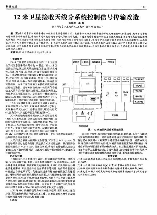
变 的位 置位 于 A C U与 A D U的通信联 系, 将现有 的传输模式 改造 为 对应不 同的问题设计不 同的解决方式 。以后把这种技术扩张开来 , 更合适 、 更可靠的传输模式 , 以此减小通信传 输的故障率 , 增 强通 信 将各 种型号卫 星接收天线 、 自动气象站 、 自动雨量 点等 中长距 离串 口信号通信设备 的传输模式改造为更 合适 、 更可靠 的传输模式 。 传输 的防护性 。
科 技 论 坛
・1 3・
1 2米卫星接收天线 分系统控制信 号传 输改造
张作君 李 娜
( 佳木斯气象卫星地 面站 , 黑龙江 佳木斯 1 5 4 0 0 7 ) 摘 要: 现行 的中长距 离信号通信一般采用 电信号传输 方式。电信 号中长距 离传输 易受外界电及 电磁影 响, 如感应雷、 电平不足 等影 响传输设备及传输质量 , 传输距 离过长也会 因电平过低 导致信 号减弱 。目前 国内外各种型号的卫星接收 天线设备及 自动气 象站设备 因研 发周期长 , 中长距 离信 号通信均采 用电信号传输 , 而国内局部地 区受雷电影响较 多, 电信 号 中长距 离传输 易受外界 电及 电磁影响 , 如 感应 雷、 电平不足 等影响传输设备及传输质量 。鉴 于近年来新的通信 传输技术的 出现 , 可以使用新的通信传输技术对 中长距 离信号通信 方式 进行改造 , 使 中长距 离信号通信更加稳定可靠 , 有利 于提 高卫星接收 天线控 制 系统、 自动 气象站数据传 输 系统、 自动雨量点数据传输 系统
受到外界强 电、 强磁干扰 , 传输速率较慢。 光信号 中长距 离传 输不受 外界 电及 电磁影响 , 传输距 离不 限 , 传输速率较 高 , 有利用 中长距离 信号通信设 备的稳定性和可靠性 。因此对 于 1 2米接收天线分系统 的天伺馈子系统 A C U — A D U通信 的改造采用光信号传输。 A C U与 A D U的通信信号 为点对点数字信号 , 采用 R S 4 2 2通信 协议 , 利用编解码器进行通信联 系工作 。因此改造时需要将光端盒 与编解 码器两端 分别加入模数转化器
地球站12米天线安装调测介绍
·69·卫星与有线传输网络总第100期地球站12米天线安装调测介绍李 良(辽宁卫星广播电视地球站)【摘 要】本文介绍了大口径卫星天线的安装、调试原理,并结合实例叙述了具体实现方法。
【关键词】天线;抛面;精度;IDPMS软件作者简介:李 良,辽宁卫星广播电视地球站,高级工程师,主要从事广播电视技术管理工作 。
辽宁卫视高清节目本地上星工程中,12m 卫星天线安装调测是一项重要环节,天线抛面的安装精度直接关系到天线增益参数,辽宁地球站采用“数字摄影测量技术”,利用IDPMS软件(智能数字摄影测量系统)对12m口径天线反射面的面板进行高精度调整,本文将介绍12m卫星天线抛面的调整方法及IDPMS软件的使用。
辽宁地球站12m天线抛面由80块曲面梯形金属板拼接而成,每块曲面梯形金属板均由6个螺丝固定在骨架上,螺丝分两段,上段用于固定曲面梯形金属面板,下段连接骨架,同时可用于调节曲面梯形金属板平整度。
天线抛面平整度的精度是否符合天线的理论模型,最终影响着天线发射和接收的增益。
在理论模型中,12m天线处于一个三维直角坐标系中,馈源中轴线为Z轴,Z轴与面板交点为原点,馈源侧方向为正方向,过原点做垂直Z轴的XY平面,XY轴方向任意。
因为每个螺丝的指向都与Z轴方向接近,受XY坐标影响很小,规定将需要调整的数值记为ΔZ(注意ΔZ 不是Z坐标误差)。
需要指出,馈源位置使用普通螺丝固定,基本不需要调整。
大口径卫星天线C波段和Ku波段的面板调整精度是一样的,每块板材上6个螺丝的ΔZ的均方根要小于0.5mm。
在没有“数字摄影测量技术”和IDPMS软件以前,大口径卫星天线是使用经纬仪调整,大致方法是:卫星天线面板拼装完成后,在吊装到天线基座之前,将抛面整体置于地面并严格保持水平;先不装馈源,将经纬仪放置于馈源约1.2m高处,再将N米长有刻度钢尺一端固定于原点,则Z轴、钢尺和经纬仪的激光成三角形;当激光正好打到所需刻度点时,该点就是该处面板理论上的位置;由于判断该点位置只能用人眼,误差较大,加之该操作需在夜间进行,并受温差影响较大,虽然理论上可以达到精度要求,但是在实际操作调试过程中耗时费力,操作繁琐,调试一部大口径卫星天线耗时在15~20天,甚至更长的调试周期。
7512Manual

PAC-12天线
PAC-12 便携多波段垂直短波天线线圈骨架是开模加工而成,材料为尼龙,强度非常高,线圈用1.0mm 的镀锡铜线绕制,所有螺丝采用不锈钢螺丝,振子铝管喷砂氧化成黑色,即使水平架设的话,下垂度也很小。
底座氧化成黑色,中国红,蓝色,定制的2.5米不锈钢拉杆天线重量轻体积小携带方便架设快捷,一个人3分钟就可以架设完毕很适合野外架台,出差旅游或者阳台架设性能参数:1. 携带重量约1.4Kg2.收缩长度约34.5cm,架设长度约410cm3.频率:可以工作在40.30.20.17.15.12.10.6米8个波段(7Mhz-50Mhz)4.阻抗:50Ω5.承载功率:200W6.SWR<1.3装箱清单:1. 铝合金底座1个(阳极氧化成黑色,中国红,蓝色,方便大家选择)2. 多波段加感线圈1个(40米- 10米,材料:尼龙,注:加感线圈为开模加工制作非手工车制)3. 地锚1个,规格10×240mm(未做电镀处理,以保持良好接地)4. 氧化铝管4个(黑色),规格19×320mm(阳极喷砂氧化)5. 顶部2.5m不锈钢拉杆天线1个(定做加厚的)6. 调节波段用的带钩螺丝1套7. 地网10股排线1根(使用时按需要撕开,一般撕开3股即可)8. 专用布包一个注:不含馈线天线使用注意事项:1 把地网的连接环直接套在地锚的螺杆上拧到底座上就可以了,注意在地锚和地网之间放上垫圈拧紧然后依次是连接座--垫片(用以防止在装接振子时刮花底座)--四节铝管--加感线圈--拉杆天线2. 带钩的调节螺丝同样不要拧的太紧,因为线圈是镀锡铜线绕制的,比较软,太紧的话就把线圈拉变形了3. 带钩的调节螺丝开口侧朝向拉杆天线,在40米波段用不到调节螺丝时,建议取下来,以防止短路线圈4. 馈线不要盘成圆圈,要把馈线全部打开,否则影响驻波的调整5.地网使用时撕开3-4根就可以了,调节地网的夹角,可以改变天线阻抗常用波段参考数据:7.050从靠近铝管一侧开始数第8圈,拉杆全部拉出,驻波1.114.270,加感线圈从靠近拉杆天线一侧开始数第6圈,拉杆天线全部拉出,驻波1.1-1.1221.4用4节铝管加拉杆天线7节+10cm左右,驻波1.229.6只用拉杆天线,全部拉出缩回半节左右,驻波1.2。
PAC-12阳台架设调试方法
PAC-12阳台架设调试方法问:水平架设你的地网不太好做,会对天线的参数改变很多,驻波不太好调。
前段时间也这么架设了一个,后来给拆了。
不知其他朋友遇到过这种情况没有?bd2bh回答:1、居住在楼宇的用户,如果pac-12在阳台/窗台水平,或者呈一定角度架设,又有幸居住地在2楼以上的话,可用一根1/4波长的地网,从窗台自然悬垂下去。
2、此时,天线已经成为一个两振子呈90°以上夹角的Dipole,因此天线需要增加1:1的巴伦。
3、同时,天线已经不能仅仅靠一只1/4波长悬垂的线段(Dipole天线的另外一臂)谐振在设计的每个波段,因此须给每个波段增加一个1/4波长的金属导线(可根据需要在适时改变悬垂线段)。
4、天线的谐振频率调整。
假如我们工作在20m波段,方法有三:一是pac-12主体和悬垂的5米振子同时调整谐振长度(比较常见的思维方法);二是根据说明书指定线圈匝数/拉杆的长度(固定天线的经验长度),然后调整天线另外一臂(悬垂振子)的长度;三是,固定悬垂线段(振子)长度,调整主振子长度/线圈。
5、当然,无论第二,还是第三种方式都不是绝对的,必要的时候也辅助调整天线的另外一臂。
比较常用、方便的方式是第三种形式。
这跟我们在汽车上或者地面上架设多波段垂直天线相类似,地网(车体)固定,只需调整天线的垂直部分。
有些正v天线,两臂的调整也不是等比例的。
这可能与加载线圈的电感不同而有所差异,也是这个道理。
因为这种类型天线架设距离楼体较近体,天线的调整可能都会相对复杂一些,相关因素比较多,找到了规律就会很快调整完毕的。
6、最后。
我倒是觉得天线这种架设形式,包括巴伦的运用,改变了天线的结构,天线已经成为了近似垂直1/2波长dipole的形式。
因此天线的信噪比、增益,特别是效率会远远高于pac-12的原本设计。
祝楼上实验者都会有所收获!。
PAC-12天线攻略(地网)
PAC-12天线攻略自从2012年4月份七公首次将此天线用于木兰围场测试赛,经过了将近一年时间的测试、使用,迄今为止已用其通联了7O6T、NH8S、3D2C、5T0SP、5X8C、6V7S、ZC4LI、A61Q、RI1FJ、T30PY、P29VCX、VE2IM以及伦敦奥运特设台等等众多远征以及稀有DX电台,至于“500W的QRP、59+60dB的QRP”等等皆是由此天线演绎出的传说,随着使用的深入对此天线的特性也有越来越多的了解,网上也有许多朋友希望七公能更详细介绍一下这款天线的具体架设以及使用方法,经过一段时间的准备,现在就将七公架设此款天线的心得体会写于此博客,期待与各位朋友一起分享,当然也肯定会有许多错误之处,不当之处还请各位朋友批评指正,打算分成三个部分来写:“地网制作篇”“天线测试篇”“天线拓展使用篇”。
需要说明的是本篇博客不是一蹴而就的,由于相关测试工作还在进行中再加之工作等等原因,本篇博客的完成也许会经历一段较长的时间,还请各位朋友多多谅解。
地网制作篇关于垂直天线的地网,七公觉得如何强调都不为过,现实中七公看到过一些朋友架设的垂直天线,主杆品类繁多,各式各样的花色品种令人目不暇接,或雄壮或绮丽,然而在观其地网的拉设却令人大跌眼镜,要么没有要么就是随随便便扔一根不知长度的电线在一旁,更认为这是可有可无之物不加重视,对此七公只能苦笑了,经过这一年来的实践,七公认为GP垂直天线地网的重要性远远大于主杆,对其越重视在地网上下的功夫越多,越能得到丰厚的回报,2012年4月木兰围场测试赛,七公首次使用此款天线的时候就拉设了9根地网,分别是10米的3根、5米的3根、3.4米的3根,分别对应于40米/20米/15米的1/4波长,取得了意外效果,也使得七公对此天线有了新的认识,其后经过反复实践,天线也由最初使用BG4DBZ出品的最初版本换成了现在BD7JPC出品的版本,无论是在外观、强度还是在实用性上都有了很大程度的提高,下面就先介绍一下七公这款天线的地网制作与配置。
DrayTek VigorAP 912C 802.11ac天花板安装式接入点快速入门指南说明书
VigorAP 912C802.11ac Ceiling-mount AccessPointQuick Start GuideVersion: 1.0Firmware Version: V1.3.0_RC1(For future update, please visit DrayTek web site)Date: July 18, 2019Intellectual Property Rights (IPR) InformationSafety Instructions and ApprovalHereby, DrayTek Corporation declares that the radio equipment type VigorAP 912C is in compliance with Directive 2014/53/EU.The full text of the EU declaration of conformity is available at the following internet address: /ftp/VigorAP 912C/Document/CE/Manufacturer: DrayTek Corp.Address: No. 26, Fu Shing Road, HuKou Township, HsinChu Industrial Park, Hsin-Chu County, Taiwan 303Product: VigorAP 912CFrequency Information for Europe area:(*1: for 2.4G WLAN model; *2: for 5G WLAN model)This product is designed for 2.4GHz and 5GHz WLAN network throughout the EC region.Federal Communication Commission Interference StatementThis equipment has been tested and found to comply with the limits for a Class B digital device, pursuant to Part 15 of the FCC Rules. These limits are designed to provide reasonable protection against harmful interference in a residential installation. This equipment generates, uses and can radiate radio frequency energy and, if not installed and used in accordance with the instructions, may cause harmful interference to radio communications. However, there is no guarantee that interference will not occur in a particular installation. If this equipment does cause harmful interference to radio or television reception, which can be determined by turning the equipment off and on, the user is encouraged to try to correct the interference by one of the following measures:●Reorient or relocate the receiving antenna.●Increase the separation between the equipment and receiver.●Connect the equipment into an outlet on a circuit different from that to which the receiveris connected.●Consult the dealer or an experienced radio/TV technician for help.This device complies with Part 15 of the FCC Rules. Operation is subject to the following two conditions:(1) This device may not cause harmful interference, and(2) This device may accept any interference received, including interference that may cause undesired operation.CautionAny changes or modifications not expressly approved by the grantee of this device could void the user's authority to operate the equipment.Any changes or modifications not expressly approved by the party responsible for compliance could void the user's authority to operate this equipment.This transmitter must not be co-located or operating in conjunction with any other antenna or transmitter.Radiation Exposure Statement: This equipment complies with FCC radiation exposure limits set forth for an uncontrolled environment. This equipment should be installed and operated with minimum distance 20cm between the radiator & your body.Operations in the 5.15-5.25GHz band are restricted to indoor usage only.More update, please visit .T a b l e o f C o n t e n t s1. Package Content (1)2. Panel Explanation (2)3. Installation (3)3.1 Ceiling-mount Installation (Wooden Ceiling) (3)3.2 Ceiling-mount Installation (Plasterboard Ceiling) (4)3.3 Suspended Ceiling (Lightweight Steel Frame) Installation (5)3.4 Wall-Mounted Installation (7)4. Connection and Configuration (8)4.1 Notifications for Hardware Connection (8)4.2 Connect to a Vigor Router using AP Management (9)4.3 Web Configurations (10)Connected As a Mesh Node (in Mesh Network) (10)Connected As an Access Point (10)5. Customer Service (13)Be a Registered Owner (13)Firmware & Tools Updates (13)1.P a c k a g e C o n t e n tTake a look at the package content. If there is anything missed or damaged, please contact DrayTek or dealer immediately.VigorAP 912C Main Unit Ceiling mount bracket & Quick StartGuideT-Rail Mounting Kits(Used for suspended ceiling)Fixings and Screws(for ceiling mounting)RJ-45 Cable (Ethernet) Screw set (for wall mounting)The type of the power adapter depends on the country that the AP will be installed: UK-type power adapter EU-type power adapterUSA/Taiwan-type power adapter AU/NZ-type Power AdapterThe maximum power consumption is 10 Watt.2. P a n e l E x p l a n a t i o nNote● For the sake of security, make the accessory kit away fromchildren.● Remove the protective film from the access point before useto ensure ventilation.Factory ResetEthernet Port3.I n s t a l l a t i o nVigorAP can be installed under certain locations: wooden ceiling, plasterboard ceilings, light-weighted steel frame and wall.3.1C e i l i n g-m o u n t I n s t a l l a t i o n(W o o d e n C e i l i n g)1.Place the bracket under the wooden ceiling and fasten two screws firmly (asshown in Figure below, Step 1).2.When the bracket is in place, fasten two screws firmly (as shown in Figurebelow, Step 2) on the bottom of VigorAP.3.Make the device just below the bracket. Put the screws installed in Step 2 onthe holes of the bracket (as shown in Figure below, Step 3).4.Gently rotate the device to make screws slide into the notches of thebracket and move forward till it is firmly fixed.BracketStep 3Step 1Step 23.2C e i l i n g-m o u n t I n s t a l l a t i o n(P l a s t e r b o a r d C e i l i n g)1.Place the bracket under the plasterboard ceiling and fasten two turnbucklesfirmly (as shown in Figure below, Step 1).2.Make the screws pass through the bracket and insert into the turnbuckles (asshown in Figure below, Step 2). Fasten them to offer more powerfulsupporting force.3.When the bracket is in place, fasten two screws firmly (as shown in Figurebelow, Step 3) on the bottom of VigorAP.4.Make the device just below the bracket. Put the screws installed in Step 3 onthe screw holes of the bracket (as shown in Figure below, Step 4).5.Gently rotate the device to make screws slide into the notches of thebracket and move forward till it is firmly fixed.Step1BracketStep 4Step 2Step 33.3S u s p e n d e d C e i l i n g(L i g h t w e i g h t S t e e l F r a m e)I n s t a l l a t i o nYou cannot screw into ceiling tiles as they are weak and not suitable for bearing loads. Your VigorAP is supplied with mounts (T-Rail brackets) which attach directly to the metal grid (…T-Rail‟) of your suspended ceili ng.1.Choose one set of T-Rail mounting kits from the bundled package.2.Put the T-Rail brackets on the holes of the bottom side of the device. Fastenthem with suitable screws.T-Rail BracketT-Rail Bracket3.If a larger gap is required between the ceiling and the VigorAP, use theextension pieces to extend the height of the brackets.Extension PieceExtension Piece4.Attach the T-Rail brackets to the ceiling frame.Note Warning: The screw set shown below is for wall mounting only.Do not use such set for ceiling mounting due to the danger offalling.3.4 W a l l -M o u n t e d I n s t a l l a t i o nFor wall-mounting, the VigorAP has keyhole type mounting slots on the underside. You can fit the AP at any axis (i.e. 12, 3, 6 or 9 O‟Clock) to allow for cable entry from the most convenient location if you are using side entry – note the position of the side entry cable cutout.1. A template is provided on the VigorAP‟s packaging box to enable you tospace the screws correctly on the wall.2. Place the template on the wall and drill the holes according to therecommended instruction.3. Fit screws into the wall using the appropriate type of wall plug (as shown inthe ceiling section) but do not use the ceiling bracket – the VigorAP hangs directly onto the screws.Wall (wooden, concrete, plasterboard or others)4.C o n n e c t i o n a n d C o n f i g u r a t i o n4.1N o t i f i c a t i o n s f o r H a r d w a r e C o n n e c t i o n●If required, remove the protective cap of VigorAP to create extra spacefor the cables to pass through.●Connect VigorAP to Vigor router (via LAN port) with Ethernet cable.●Connect VigorAP to PoE switch (via LAN port) with Ethernet cable. Forconnecting with PoE switch, do not connect the power adapter. VigorAPwill get the power from the switch directly.4.2C o n n e c t t o a V i g o r R o u t e r u s i n g A P M a n a g e m e n tYour VigorAP can be used with Vigor routers which support AP management (such as the Vigor2862 or Vigor2926 series). AP Management enables you to monitor and manage multiple DrayTek APs from a single interface.1.Connect one end of the power adapter to power port of VigorAP, and theother side into a wall outlet.2.Access into the web user interface of Vigor router. Here we take Vigor2862as an example. Open Central Management>>AP>>Status.3.Locate VigorAP 912C. Click the IP address assigned by Vigor router to accessinto web user interface of VigorAP 912C.4.After typing username and password (admin/admin), the main screen will bedisplayed.4.3W e b C o n f i g u r a t i o n sThis section will guide you to install the AP and make configuration for VigorAP.C o n n e c t e d A s a M e s h N o d e(i n M e s h N e t w o r k)❶Install VigorAP on to the ceiling.❷As a mesh node, settings related to VigorAP 912C must be configured by a remote Mesh Root (e.g., VigorAP 903) within the mesh network.The user must detect VigorAP 912C via a Mesh Root to add it as a meshnode.C o n n e c t e d A s a n A c c e s s P o i n tAs an access point, VigorAP 912C must be connected to a router and configured in AP (Access Point) / Range Extender mode.❶Install VigorAP on to the ceiling.❷Use a twisted-pair cable with RJ-45 plugs at both ends, and plug into Ethernet device (e.g., Vigor router) and Ethernet port of VigorAP.❸There are two methods to configure VigorAP.Method 1:(a)First, open a web browser on your PC and type https://192.168.1.2. Apop-up window will open to ask for username and password.Note You may either simply set up your computer to get IPdynamically from the router or set up the IP address of thecomputer to be in the same subnet as the IP address ofVigorAP 912C.●If there is no DHCP server on the network, then VigorAP912C will have an IP address of 192.168.1.2.●If there is DHCP available on the network, then VigorAP912C will receive its IP address via the DHCP server.●If you connect to VigorAP by wireless LAN, you could tryto access the web user interface through.(b)After clicking Login, Quick Start Wizard for configuring wirelesssettings will appear as follows.(c) Follow the on-screen steps to finish the network connection.Method 2:(a) Use a mobile phone to scan the QR code named with DrayTek WirelessApp to download DrayTek Wireless APP.(b) After downloading, run the APP. (c) Click Quick Start Wizard. Next, scan the QR code named with ConnectSSID . Later, click Connect to access into the APP user interface ofVigorAP 912C to set the device in AP or Range Extender mode.5.C u s t o m e r S e r v i c eIf the device cannot work correctly after trying many efforts, please contact your dealer/DrayTek for further help right away. For any questions, please feel free to send e-mail to “*******************”.B e a R e g i s t e r e d O w n e rWeb registration is preferred. You can register your Vigor router via.F i r m w a r e&T o o l s U p d a t e sDue to the continuous evolution of DrayTek technology, all routers will beregularly upgraded. Please consult the DrayTek web site for more information on newest firmware, tools and documents.。
- 1、下载文档前请自行甄别文档内容的完整性,平台不提供额外的编辑、内容补充、找答案等附加服务。
- 2、"仅部分预览"的文档,不可在线预览部分如存在完整性等问题,可反馈申请退款(可完整预览的文档不适用该条件!)。
- 3、如文档侵犯您的权益,请联系客服反馈,我们会尽快为您处理(人工客服工作时间:9:00-18:30)。
PAC-12天线攻略
自从2012年4月份七公首次将此天线用于木兰围场测试赛,经过了将近一年时间的测试、使用,迄今为止已用其通联了7O6T、NH8S、3D2C、5T0SP、5X8C、6V7S、ZC4LI、A61Q、RI1FJ、T30PY、P29VCX、VE2IM以及伦敦奥运特设台等等众多远征以及稀有DX电台,至于“500W的QRP、59+60dB的QRP”等等皆是由此天线演绎出的传说,随着使用的深入对此天线的特性也有越来越多的了解,网上也有许多朋友希望七公能更详细介绍一下这款天线的具体架设以及使用方法,经过一段时间的准备,现在就将七公架设此款天线的心得体会写于此博客,期待与各位朋友一起分享,当然也肯定会有许多错误之处,不当之处还请各位朋友批评指正,打算分成三个部分来写:“地网制作篇”“天线测试篇”“天线拓展使用篇”。
需要说明的是本篇博客不是一蹴而就的,由于相关测试工作还在进行中再加之工作等等原因,本篇博客的完成也许会经历一段较长的时间,还请各位朋友多多谅解。
地网制作篇
关于垂直天线的地网,七公觉得如何强调都不为过,现实中七公看到过一些朋友架设的垂直天线,主杆品类繁多,各式各样的花色品种令人目不暇接,或雄壮或绮丽,然而在观其地网的拉设却令人大跌眼镜,要么没有要么就是随随便便扔一根不知长度的电线在一旁,更认为这是可有可无之物不加重视,对此七公只能苦笑了,经过这一年来的实践,七公认为GP垂直天线地网的重要性远远大于主杆,对其越重视在地网上下的功夫越多,越能得到丰厚的回报,2012年4月木兰围场测试赛,七公首次使用此款天线的时候就拉设了9根地网,分别是10米的3根、5米的3根、3.4米的3根,分别对应于40米/20米/15米的1/4波长,取得了意外效果,也使得七公对此天线有了新的认识,其后经过反复实践,天线也由最初使用BG4DBZ出品的最初版本换成了现在BD7JPC出品的版本,无论是在外观、强度还是在实用性上都有了很大程度的提高,下面就先介绍一下七公这款天线的地网制作与配置。
首先,来看看地网长度的取舍,理论上来说1/4波长应该是最佳选择,那么相关波段的数值七公列了一个表如下:
波长(单位:米)长度(单位:米)
10 2.48
12 2.87
15 3.37
17 3.95
20 5.04
307.06
4010.14
8019.59
16037.63
以上的数据只是参考,各位朋友在实际运用中也不必要如此精确与苛求,大概差不多就是行了
地网使用的线径是越粗越好,但很细的线似乎也没问题,七公使用的是当初BD6QBY老弟友情赠送的一卷0.2的线
七公的地网是对照上表,按20米/17米/15米/12米/10米五个波段来截取为一组,一共是三组共计15根
接线头是市场上购买的直径为10的压线头(方便套在直径为10的地钉上)
除了以上的配置以外,七公似乎觉得还不够过瘾,于是找本地的钳工师傅对天线底座再一次做了小小的改动,围着天线底座每120度钻一个直径4毫米的孔,一共3个,然后买来香蕉插头,每个插头压入5根1.5米长的网线,这样一来又有15根地网可以加入,在现有的条件下不断挖掘此款天线的潜力,提高效率就是QRPer七公的追求。
一图胜过千言万语,下面就用图示来看看七公每次是如何来架设PAC-12地网的吧
1、看看合影,这就是七公户外野战时的天线配置
2、专门配备了一把锤子,注意要用橡胶头的,以免在打入地钉的时候损伤地钉上的螺纹
3、打入地钉后,将做好的地网依次套上,注意要呈现360度的均匀分布。
4、拧上底座并将15根地网均匀散开分布拉设
5、最后将3个香蕉头共15根由1.5米网线做的地网插入底座中后来加工好的孔内,这样一个完整的地网就架设完毕了。