丁玉成等综述Ordering, positioning and uniformity of quantum dot arrays
国际航运中心的发展模式(续篇1)
国际航运中心的发展模式(续篇1)
顾家骏
【期刊名称】《航海科技动态》
【年(卷),期】1999(000)007
【总页数】4页(P2-5)
【作者】顾家骏
【作者单位】无
【正文语种】中文
【中图分类】U692.22
【相关文献】
1.国际航运中心的变迁与发展模式研究——基于史料的案例分析 [J], 王学锋;陈扬;金琳;朱昱音
2.国际航运中心的发展模式(续篇2) [J], 顾家骏
3.大连国际航运中心的发展模式及对策研究 [J], 苗秀杰;戚静静
4.上海国际航运中心发展模式选择 [J], 李智慧
5.大连国际航运中心的发展模式及对策研究 [J], 苗秀杰;戚静静
因版权原因,仅展示原文概要,查看原文内容请购买。
现代城市综合体中的传统空间礼序探讨——以济宁文化科技融合创新中心为例
1672023.17 / Architectural Design and Theory 建筑设计·理论现着多元风格。
济宁历史文脉的延续,多元共生是必然趋势,也是社会从封闭走向开放的必然结果[2]。
在有如此文化内涵的城市,且在新区城市地标集群中做项目设计,除了应满足项目自身需求,也需要对其地标性、公共性、文化性加以考虑和回应,将城市的多元文化延续下去。
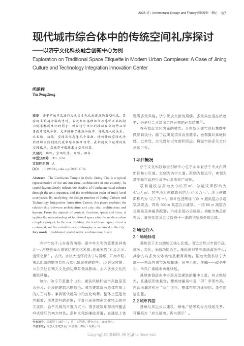
1项目概况济宁文化科技融合创新中心位于山东省济宁市太白湖新区核心区域,北侧为济宁大道,西侧为新运河,南侧为济宁新市政府行政中心及市民广场等。
项目建设总用地为9.08万m 2,总建筑面积约为47.5 万 m 2,其中地上建筑面积约为34.8万m 2,地下建筑面积约为12.7万m 2。
项目包括两栋130 m 超高层办公建筑及酒店、四栋100 m 高层办公建筑、一栋60 m 高层办公建筑及其裙房配套,六栋多层办公建筑。
功能为集总部办公、商务交流及会议接待于一体的创新商务综合体。
2场地介入2.1场地脉络基地位于太白湖新区核心区域,周边功能以市级行政、商务、文化、金融功能为主。
基地南部紧邻市级政务中心,其余方向多为文体场馆及教育用地。
基地北侧临济宁大道——东西向城市发展轴线;居中为南北主轴——政务中心、市民广场城市南北轴线。
基地南侧政务中心是周边建筑的重中之重,其占地较大,且建筑形体复合,最高体量居中呈“四”字形布局,东西两翼对称呈“日”字形,整体布局方正规则,造型简洁庄重。
2.2城市界面基地与周边公共建筑、绿地广场等均存在视线关系,可概括为“府北路南、两向展示”。
摘要 济宁市曲阜孔庙作为我国古代礼制建筑的典型代表,其空间布局通过轴线序列、多进制院落的组合秩序明显地折射出儒家礼制文化的影子。
结合济宁文化科技融合创新中心项目设计实践分析,文章阐释了建筑与城市、场地及人的关系,从文脉、功能、空间及形态等几个层面,将对传统空间礼序的理解实践到现代城市综合体项目中。
基于循环经济的供应链核心竞争力评价指标体系研究
出口贸易对技术创新的影响研究综述
出口贸易对技术创新的影响研究综述田朔;李平【摘要】全球化背景下,国际市场较强的竞争及伴随出口贸易商品的流动而产生的技术溢出等都能使得出口商获得技术优势,形成较高的技术创新能力;同时,相关贸易政策通过影响贸易规模、贸易质量等方面促使企业进行技术创新。
随着各国对外开放程度的不断提高,出口贸易大幅增长,对于如何利用出口贸易刺激并实现技术进步的研究具有现实意义。
在综述近年来出口贸易对本国技术创新影响的主要文献的基础上,将其影响归纳为竞争引致创新效应、技术溢出效应及政策影响等方面,为该领域的深入研究提供有益思路% Against the background of globalization, relationships between countries are increasingly significant, and international competitions as well as technology spillovers with flows of export goods make exporters gain more tech⁃nological advantage and form higher innovative capacities. Meanwhile, relative trade policies enable exporters to carry out technological innovation by influencing trade scale, trade structure, trade quality and so on. Along with China’s opening up and the increase of export, how to stimulate and realize China’s technological advancement by using export is significantly practical. This paper reviews the main studies made at home and abroad on the effects of the export on technological innovation and summarizes the specific effects, which aims to analyze the effects of the export on technological innovation systematically.【期刊名称】《常熟理工学院学报》【年(卷),期】2012(000)005【总页数】5页(P40-44)【关键词】出口贸易;技术创新;竞争引致创新;技术溢出;政策法规【作者】田朔;李平【作者单位】山东理工大学商学院,山东淄博 255012;山东理工大学商学院,山东淄博 255012【正文语种】中文【中图分类】F740一、引言在国际贸易理论的演进过程中,技术要素一直贯穿其中,产品生命周期理论、新贸易理论以及内生增长理论等揭示了国际贸易和技术创新之间存在的相互促进关系。
物流系统的复杂适应性研究
文章编号:1002-3100(2010)02-0001-04收稿日期:2009-11-18基金项目:国家教育部人文社会科学规划项目,项目编号:09YJA630112。
作者简介:万志成(1984-),男,河北唐山人,天津科技大学经济与管理学院硕士研究生,研究方向:管理信息系统;慕静(1966-),女,山西大同人,天津科技大学经济与管理学院,教授,博士、硕士研究生导师,研究方向:系统科学与规范管理、物流系统与供应链。
Logistics Sci-Tech No.2,2010物流科技2010年第2期摘要:在介绍物流系统的基础上,运用复杂适应系统理论对物流系统的基本特征进行了分析,证明它是一个复杂适应系统,并分析了物流系统的复杂适应性,构建了物流系统复杂适应性的概念模型。
结果表明,物流系统是一个典型的复杂适应系统,具有学习演化、协同进化、涌现、动态性和环境的交互作用的复杂适应性特征。
关键词:物流系统;复杂性;适应性;概念模型中图分类号:G301:N941文献标识码:A Abstract:This paper introduces the logistics system,applies complex adaptive systems theory to analyze the logistics sys -tem's basic features and proves that logistics system is acomplex adaptive system,then builds a conceptual model ofcomplex adaptability of the logistics system by analyzing com -plex adaptability of the logistics system.The result shows thatthe logistics system is a typical complex adaptive system,which has complex adaptive characteristics of learning evolu -tion,co-evolution,emergence,dynamic and interaction of envi -ronment.Key words:logistics system;complexity;adaptability;concep -tual model 物流系统的复杂适应性研究Research on Complex Adaptability of Logistics System万志成,慕静(天津科技大学经济与管理学院,天津300222)WAN Zhi-cheng,MU Jing(College of Economics &Management,Tianjin University of Science &Technology,Tianjin 300222,China)在日益全球化和网络化的现代社会中,随着国内物流市场的开放,竞争愈加激烈,物流企业面临巨大挑战。
哈萨克斯坦主要农机需求量预测分析
第42卷第1期2021年1月中国农机化学报JournalofChineseAgriculturalMechanizationVol42No1Jan2021DOI:10.13733/j.jcam.issn.2095—5553.2021.01.019哈萨克斯坦主要农机需求量预测分析楚天舒S王德睿S韩鲁佳杨增玲成天一1(1.中国农业大学工学院,北京市100083; 2.中国农业大学烟台研究院,山东烟台,264670)摘要:哈萨克斯坦农业资源丰富,发展潜力巨大,农业是中哈两国合作的重点领域之一)然而,受制于农业机械老旧和国内机械设备产能落后,哈萨克斯坦农业机械化与现代化发展缓慢)由于哈萨克斯坦国家政府对农业机械化发展的支持,中哈在农机技术与产品方面的贸易往来势必加强)本研究以黑龙江农垦与新疆生产建设兵团的农机装备水平为参考对象,预测分析哈萨克斯坦主要农机需求量与市场潜力)研究发现哈萨克斯坦农机需求量大,拖拉机、排灌机械、植保机械、收获机械和播种机械预测市场潜力分别为575万台、27万台、64万台、82万台、147万台以上)此外,由于农业经济基础薄弱,哈萨克斯坦短时间内不可能达到预测的农机数量,但可作为其未来农业机械化与现代化发展的参考)关键词:哈萨克斯坦;农业机械;预测需求量;农机产业中图分类号:S23文献标识码:A文章编号:2095-5553(2021)01-0136-07楚天舒,王德睿,韩鲁佳,杨增玲,成天一.哈萨克斯坦主要农机需求量预测分析+,中国农机化学报$021,42(1):136—142Chu Tianshu,Wang Derui,Han Lujia,Yang Zengling,Cheng Tianyi.Forecast demand for Kazakhstan's major agricultural machinery[J,Journal of Chinese Agricultural Mechanization,2021,42(1):136—1420引言在“一带一路”倡议提出后,中国与哈萨克斯坦的政治、经济、文化等方面交流日益密切。
《淋浴器用水效率限定值及用水效率等级》国家标准解读
Research on "Public Procurement Basic Vocabulary
"
作者: 丁玉珍[1] 邢献军[1] 白雪[2] 朱双四[1]
作者机构: [1]国家排灌及节水设备产品质量监督检验中心,合肥230601 [2]中国标准化研
究院,北京100088
出版物刊名: 标准科学
页码: 73-75页
年卷期: 2012年 第10期
主题词: 淋浴器 流量 用水效率等级 用水效率限定值 节水评价值
摘要:淋浴器是家庭中主要用水器具,标准根据流量的大小对其进行节水性评价,本文介绍了《淋浴器用水效率限定值及用水效率等级》标准的制定背景,并对该水效标准的主要技术条
款作了详细的解说,便于标准使用者更好地理解和把握标准的内容。
健全和完善中国粮食市场体系
Perfecting China' s Food Market System 作者: 丁声俊[1];朱玉辰[2]
作者机构: [1]中国市场学会,北京100037;[2]大连商品交易所,大连116000
出版物刊名: 国家行政学院学报
页码: 48-51页
主题词: 中国;粮食市场体系;市场机制;管理体制;多元化;粮油商品;市场监控系统
摘要:经过20余年的改革、培育和发展,中国粮食市场体系建设已经取得重大绩效,发挥了重大作用,但是该体系市场机制发育滞后,管理体制政出多门,职责不清.新时期的改革总体思路是,发展多元化、多类型、多形式的统一、开放、竞争、有序的粮食市场体系,达到强农、利民、兴企、益国的目标.。
DATA TRANSMISSION METHOD AND APPARATUS
专利名称:DATA TRANSMISSION METHOD AND APPARATUS发明人:DING, Zhiming,丁志明,HAN, Yunbo,韩云博,ZHUANG, Hongcheng,庄宏成申请号:CN2017/107973申请日:20171027公开号:WO2019/015157A1公开日:20190124专利内容由知识产权出版社提供专利附图:摘要:Provided in the present application are a data transmission method and apparatus. The method comprises: the network device receives first request informationsent by a first terminal device over first transmission request resources, the first request information being used for requesting the use of the first data transmission resources, the first data transmission resources belonging to periodic data transmission resources pre-configured by the network device for the first terminal device; the network device sends authorisation response information to the first terminal device over first transmission authorisation resources, the first authorisation response information being used for indicating that the first terminal device can use the first data transmission resources; and the network device receives uplink data sent by the first terminal device over the first data transmission resources. Thus, the terminal device can determine resources used for uplink data transmission as quickly as possible by means of less message exchange, and thus perform uplink data transmission as quickly as possible, helping or possibly reducing the latency in performing uplink data transmission.申请人:HUAWEI TECHNOLOGIES CO., LTD.,华为技术有限公司地址:Huawei Administration Building Bantian, Longgang Shenzhen, Guangdong 518129 CN,中国广东省深圳市龙岗区坂田华为总部办公楼, Guangdong 518129 CN 国籍:CN,CN代理人:LONGSUN LEAD IP LTD.,北京龙双利达知识产权代理有限公司更多信息请下载全文后查看。
基于管理成熟度评估模型的职业院校诊断与改进方法研究与实践
『20151168号 )文件 后 ,全 国已有27所 职 业 院校 开展 绩 效 准 则 》(Criteria for Performance Excellence)
了试 点 工作 。目前 ,各 省 高 等 职 业 院校 诊 断与 改 中的评 分 系统 (以下 简 称 “卓 越 绩 效模 式 评 分 系
进 理论 研 究 和实 践 也方 兴未 艾 ,从 发 表 的论 文 或 统 ”)提 供了一 套 对管 理 要 素量 化评 分 方 法 ,但评
出版 的专 著来 看 ,主 要 研 究 方 向为 诊 改 的作 用 、 分系 统 非常 复 杂 ,其 分 为过 程 和结 果 两个 评 分维
内涵和工作内容,即对诊改工作 “为什么”“是什 度 ,每 个 维 度 内部 有 六个 等级 ,每 个 等 级 内部又
我 评 价工 具 中 的描 述 详 细 、具 体 。用 于 开展 诊 断与 改 进 工 管 理 工具 中的先 进 理论 、方 法 .吸 纳其优 势 并尽量 规 避 其 不
作 ,不 宜 理解 和 操作 ,评 分 也有 些难 度 。
足 ,学 校 与管 理 咨询 机 构 共 同 创 造 性 地设 计 适 用 于 职 业
院 校诊 断与 改 进 的工 具— — 《职业 院校 管 理 成 熟 度 评 估 模
二、适 用于 职业 院校 诊 改的管理 成熟 度评 型 (2017版 )》 (以下简 称 “本 模 型 ”),并 用 于两 所 职 业改 实践 ,这 对 深 化 职 业 院校 的 诊 改 工作 有一 定 的借 鉴 意义 。表 l为本 模 型 的框架 和 内容。
基金会 )卓越模 式 (EFQM Excellence Mode)的 i ;
ISO9004《追求组织的持续成功一一质量管 RADAR评分矩阵(以下简称“EFQM-@ ̄
- 1、下载文档前请自行甄别文档内容的完整性,平台不提供额外的编辑、内容补充、找答案等附加服务。
- 2、"仅部分预览"的文档,不可在线预览部分如存在完整性等问题,可反馈申请退款(可完整预览的文档不适用该条件!)。
- 3、如文档侵犯您的权益,请联系客服反馈,我们会尽快为您处理(人工客服工作时间:9:00-18:30)。
Nano T oday(2012)7,94—123REVIEWOrdering,positioning and uniformity of quantumdot arraysHongbo Lan a,b,∗,Yucheng Ding a,∗a Centre for Micro and Nano Manufacturing,State Key Laboratory for Manufacturing System Engineering,Xi’an Jiaotong University,Xi’an710049,Chinab Nanomanufacturing and Nano-Optoelectronics Lab,Qingdao T echnological University,Qingdao266033,ChinaReceived30October2011;received in revised form16February2012;accepted20February2012Available online16March2012KEYWORDSQuantum dot arrays;Uniformity andordering;Site control;Patterned substrateSummary Quantum dot(QD)arrays have now been attracting tremendous attention due tothe potential applications in various high performance devices(e.g.,QD lasers,3rd generationsolar cells,single photon emitters,QD memories,etc.),the fundamental investigation of quan-tum computing and quantum communication,and in the exploration or observation of novelphysical phenomena.Uniform and regular QD arrays with precisely controlled positions andsizes may serve as a template for the next generation of nanoelectronic and optoelectronicdevices.Currently,the major challenging issues in commercialized application of QD arraysinclude fabrication of large-area,defect-free,highly uniform and ordering QDs,accurate posi-tioning for individual QD nucleation site,and reproducibility in size and spatial distribution,which all crucially determines optoelectronic performance and consistency for these QDs-basedfunctional devices and the investigation of fundamental physical properties for QDs.Over thepast decade,enormous attempts have been made to improve the ordering,positioning,unifor-mity,and defect reduction for obtaining perfect QD arrays over a large area with long rangeordering.This article provides a review of some major attempts and progresses recently madefor enhancing the ordering,positioning and uniformity for QD arrays,with an emphasis on theproblems which has been well addressed to reach the current state of the arts.Furthermore,theprospects,challenges and trends for producing high quality QD arrays with high ordering,uni-formity,positioning and defect reduction,are addressed.Finally,some potential or promisingsolutions for achieving perfect QD arrays are discussed.©2012Elsevier Ltd.All rights reserved.∗Corresponding authors at:Centre for Micro and Nano Manufac-turing,State Key Laboratory for Manufacturing System Engineering,Xi’an Jiaotong University,Xi’an710049,China.T el.:+862983399518;fax:+862982660114.E-mail addresses:hblan99@(n),ycding@(Y.Ding).IntroductionQuantum dots(QDs)are nanoscale and three-dimensionallyconfined semiconductor structures,which exhibit quantumeffects such as sharp density of states.Semiconductor quan-tum dot structures have now been attracting great interestbecause of their peculiar physical properties as well as1748-0132/$—see front matter©2012Elsevier Ltd.All rights reserved.doi:10.1016/j.nantod.2012.02.006Ordering,positioning and uniformity of quantum dot arrays95their potential applications in high performance devices[1]. The unique advantages of quantum dot ensembles or indi-vidual QD can be fully harvested only if the dots are as uniform as possible in shape and size and the correspond-ing nucleation sites are precisely positioned.In particular, quantum dot arrays with high uniformity,positioning and ordering have demonstrated the great potential for a wide variety of applications,ranging from nanoelectron-ics,optoelectronics quantum functional devices operating at telecom wavelengths,to quantum information process-ing and quantum computing(e.g.,QD lasers,solar cells, single-electron transistors,single photon emitters,QD mem-ories,infrared photodetectors,etc.)[2—4].However,the industrialized application of QD arrays is faced with some major challenging issues,including generation of defect-free,highly uniform and ordering QDs over a large-area, accurate controlling of individual QD nucleation site,as well as reproducibility in size and spatial distribution,which can play a crucial role in the realizations and further per-formance improvement of these QDs-based devices and in the investigation of fundamental physical properties con-cerning the QDs.Since optical and electrical properties, and acute responses essentially depend upon the unifor-mity of QD size,shape and composition,and upon a precise positioning of individual QD nucleation site,as well as pre-dictable and reliable controlled applications,large-area QD arrays with uniformity and perfect long range ordering are demanded.The large sizefluctuation of QDs results in signif-icant inhomogeneous broadening,diminishing the potential advantages of their use in optoelectronic devices,such as those with low threshold current density,narrow gain band-width,and increased critical temperature.Numerous studies have been performed to explore the processes for producing QD arrays with accurate site con-trol(high ordering and positioning)and with identical size, shape,and composition(high uniformity).Such quantum dot arrays would be desirable for realizing high performance lasers or photonic crystal devices,single photon emitters, as well as for inducing efficient coupling between QDs and cavity modes[2—4].For instance,an ideal QD laser should consist of high density3D QD arrays with equal size and shape surrounded by a higher bandgap material which con-fines the injected carriers.The whole structure is embedded in an optical waveguide consisting of lower and upper cladding layers[5].One of the most promising and chal-lenging methods for achieving high power efficiency(>60%) solar cells is to utilize periodic3D arrays of the semiconduc-tor quantum dots[6,7].Highly ordered InAs/InP quantum dot arrays(1D,2D,3D)are the basis for the realization of novel quantum functional devices operating at telecom wave-lengths[8].For single photon emitters and device integration,the ability to place an individual QD precisely at a pre-defined location is of great ly,QD arrays with accurately positioned nucleation sites and a low density are critical.Moreover,the precise position control of individual quantum dots in an array is also necessary for the integration in photonic cavities or for further processing of the devices[8].Laterally ordered semiconductor QD arrays are highly demanded due to the shrinking feature sizes in microelec-tronics and especially in the emerging quantum functional devices employing semiconductor QDs[9,10].The control of lateral QD alignment has been considered as the key to next generation quantum functional and optoelectronic devices where quantum mechanical and electromagnetic interactions of single and multiple electrons and photons are well-controlled within the ordered QD networks[3,8]. Perfectly ordered QD arrays are also required for the obser-vation of novel physical phenomena such as interference effects[11]and enhancement of excitonic optical nonlin-earities[3,8].The realization of well-positioned QD arrays, thus,gives rise to interesting physical phenomena which modify the fundamental material properties,providing the basis for nanoelectronics/optics in future functional devices utilized for quantum information processing and quantum computing.In addition,coupled QD array system with dot-to-dot interaction is a very promising candidate for the logical unit in a quantum computer,as called‘‘qubit’’or quantum bit,which in principle can be realized by a two-level quantum system,e.g.,the horizontal or vertical polarization of a photon or the up and down states of an electronic spinning[12,13].Thus,not only the size,shape, and emission wavelength control are needed,but also is a spatially well-positioned QDs nucleation essential[9,14,15].QDs can be formed by epitaxial growth from the vapor phase molecular beam epitaxy(MBE),metallo-organic chemical vapor deposition(MOCVD),chemical synthesis (colloidal chemistry or electrochemistry)and semiconductor processing methods.Conventional semiconductor process-ing techniques based on lithography and etching are faced inherently with problems such as limited resolution,high cost,and possible introduction of surface defects,which tend to degrade the optical and electrical properties of QD-based devices[16].One of the most promising approaches for fabricating low-dimensional semiconductor QDs is a self-assembly process under the Stranski—Krastanov(S—K) growth mode.The self-assembled quantum dots nucleate spontaneously under certain conditions during MBE and MOCVD,when a material is grown on a substrate to which it is not lattice-matched.The growth initially progresses with a pseudomorphic growth mode forming a strained2Dfilm, the wetting layer.When this strain accumulates in thefilm and reaches a certain amount at the critical thickness,the growing material matrix may experience a phase transition from a2D layer-by-layer growth to a3D island growth.This growth mode is known as Stranski—Krastanov(S—K)growth. The important term to determine the S—K growth mode is the lattice mismatch between the two epitaxial layers.For instance,the common combination of InAs and GaAs has a lattice mismatch of7%,Ge/Si system has a lattice mismatch of4%.The islands can be subsequently buried to form the QDs.The semiconductor QDs grown by S—K growth mode has been well established as a reliable growth technique, and also considered as one of the most promising candidates for applications in QD-based devices due to the ease in fab-rication and their high-quality,defect-free properties.The QDs grown by S—K growth mode are defect-free giving rise to structural and optical properties of a high quality.How-ever,due to the inherent limitation of the self-assembling process(this approach is not ideal and is complicated by the randomness of the QD size distribution and inherent presence of the wetting layer.Furthermore,wetting layers are inevitably produced as a step in the formation process of self-assembled QDs),the QDs sizefluctuation,materialn,Y.Dingintermixing,and randomly distributed nucleation sites are inevitable.But,the large size variation of these QDs typically results in significant inhomogeneous broadening, diminishing the potential advantages of their use in opto-electronic devices.For an ideal case,the energy levels of all QDs should be the same.This means that the size,shape,and composition of the QDs need to be identical to the greatest extent.Then,the inhomogeneous broadening of QD lumines-cence due to sizefluctuations can be eliminated,resulting in a real concentration of the electron energy states[8].In addition,controlling the nucleation site of quantum dots is also one of the key issues in the nano-scale design of optoelectronic functional QD devices.Furthermore,the site-control plays an essential role for these QDs used for quantum computing and quantum communications,since a regular array of quantum bits and a single photon emit-ter can be formed by this technique.However,this random nucleation makes it difficult to address each individual self-assembled QD.It is a big challenge to reproduce and exactly control the nucleation site of each individual QD.Moreover, another disadvantage associated with self-assembly is its inability to create long-range-ordered structures[17].The QDs were formed using the S—K growth mode.The area densities range between2×1010and l×1011cm−2with a typical size distribution of∼10%[5].Some functional QD devices such as QD laser,QD memory require a large num-ber of QDs in the desired region with a high density.On the other hand,considering the application of QDs in sin-gle photon-emitting devices,such as a microcavity quantum electro-dynamics device,in order to isolate single QD emis-sion in practical device structures a QD density approaching 108cm−2is required(the density of QDs should be rather low).In other words,it is preferred that one QD is formed at the center of the cavity where the electricfield is maxi-mum,in order to achieve high-performance operation.It is very difficult for QDs grown by S—K growth mode to obtain low density QDs.It is almost impossible to place QDs in an organized way and at predesigned locations.Therefore,in a summary,applicability of QD arrays may at least be faced with the following challenging issues:1)Homogeneity(uniformity)of QD arrays in size,shape andcomposition;2)Accurate positioning of individual QD nucleation site inQD arrays;3)Proper control(tuning)of QD arrays density from lowdensity to high density;4)Generation of large area,high density,long-range order-ing QD arrays with high optical property;5)Mass production of perfect QD arrays over large area.In order to achieve large-area,defect-free QD arrays with high uniformity and ordering(also called perfect QD arrays),a number of investigations and efforts have been performed over the past decade.The objective of this paper is to present a comprehensive review of recent advances in creating highly ordering and uniform,well-positioning QD arrays.Furthermore,the prospects,challenges and future development directions of making high quality QD arrays are also addressed and discussed.As a result,some possible or promising solutions for achieving perfect QD arrays are discussed.The paper may provide a reference and direction for the further explorations and studies of perfect QD arrays.The rest of this paper is organized as follows.Sec-tion‘Basic characteristics and a classification of QD arrays’introduces principal characteristics and classification of QD arrays.Section‘Formation of QD arrays on non-patterned substrates’presents the formation of QD arrays on non-patterned substrates.Generation of QD arrays on patterned substrates are described in detail in section‘Generation of QD arrays on patterned substrates’.Furthermore,some other methods for fabricating QD arrays are also addressed in section‘Other approaches for formation of QD arrays’.In addition,three key issues are discussed in section‘Discus-sions for three key issues’.Prospects,challenges and trends in producing perfect QD arrays are elaborated in section ‘Discussions for three key issues’.Finally,section‘Conclu-sions’summarizes this paper.Basic characteristics and a classification of QD arraysPrincipal characteristicsSome key concepts or characteristics arefirstly addressed which can play an important role to accurately describe the properties of QD arrays and better understand the nature of QD arrays.These features of QD arrays are described as follows.Density(high density and low density)The density of QD arrays(i.e.,the number of QDs over a unit area)can be roughly divided into high density(>1010cm−2) and low density(<108cm−2).Some QD devices require a large number of QDs in the desired region with a high density. For instance,the requirement of QD density for the inter-mediate band solar cells(IBSC is about5—10×1010cm−2); the sheet density is estimated to be about1011cm−2for high efficient QD lasers.On the other hand,some QD-based devices and applications(e.g.,single photon emitters and microcavity quantum electro-dynamics device),low density (dilute)QD arrays and single QD are required and desirable. In other words,it is preferred that one QD is formed at the center of the cavity where the electricfield is maximum,in order to achieve high-performance operation.The density ranging from2×1010to l×1011cm−2with a size distribu-tion of∼10%is the typical range for S—K QD ensembles. S—K growth beyond this range is certainly difficult but may be achieved and was reported.However,it is very difficult to achieve low density QD arrays by the self-assembly pro-cess.The QDs growth on patterned substrates has the ability to achieve both high dense QDs and low dense QDs.Growth on the patterned substrates has been shown to result in a low QD density,by preferential QD nucleation in nanoholes or growth of QDs on pyramidal structures.Alternatively, it is also possible to significantly control reducing the QD density on conventional substrates through accurate con-trol of growth conditions,for example by reduction of the InAs quantum dot growth rate together with further sam-ple treatment such as mesa etching to isolate the single QD emission has been demonstrated[9,18,19].Ordering,positioning and uniformity of quantum dot arrays 97Ordering (lateral ordering and vertical ordering;short-range ordering and long-range ordering)The ordering of QD arrays involves generally two aspects:lateral ordering and vertical ordering;short-range ordering and long-range ordering [3,17,20].The lateral ordering of QDs (lateral alignment of QDs)refers to that the QDs can accurately control the nucleation site in a planar .The lateral ordering of self-assembled QDs and QD arrays has been under investigation because many emerging QD-based devices such as single photon emitters or single turnstile devices will eventually require the strict positioning of individual QD.A variety of approaches have been employed to obtain lat-eral ordering.The most promising approach to force QDs into lateral order seems to be the growth on patterned sub-strates.It is important to form electrically and optically active QD layers with perfect crystal quality far away from the contaminated interface.Therefore,the vertical align-ment of QDs is a useful technique to transfer the initial surface modulation to the growth front through laterally strain-modulated buffer layer .This buffer layer can consist of a laterally strain-modulated superlattice or stacked self-assembled QDs.The self-assembled QDs stacked would form a three-dimensionally ordered QD superlattice.Vertical ordering can be improved by the multilayer stacking pared to the vertical ordering,the lateral ordering of QDs and QDs arrays may play a much more important role for QD-based devices and applications.Various methods includ-ing strained multilayer stacking,pre-patterned substrates,multi-atomic steps,cleaved edge overgrowth,and multi-layer stacking on high-index substrates have been proposed to enhance the lateral and vertical ordering of QDs and QD arrays [3].Three-dimensional stacking of self-assembled QDs in multilayers or superlattice structures has turned out to be one of the most effective techniques for control-ling the vertical and lateral arrangement of the QDs.The semiconductor QDs grown by S—K growth mode can obtain QD arrays with short-range ordering.The primary disadvan-tage associated with self-assembly is its inability to create long-range-ordered structures.However ,long-range order characterizes physical systems in which remote portions of the same sample exhibit correlated behavior .Long-range ordering quantum dot arrays might be useful for a high inte-gration of single quantum dot devices,or to realize one,two,and three-dimensional quantum dot crystals.It is this lack of long-range order that prevents the widespread use ofself-assembly for many technological applications.The QDs growth on the patterned substrates has the ability to create the QD arrays with long-range ordering.Unfortunately ,the technique is hard to make such defect-free QD arrays hav-ing long-range ordering [21].Many efforts to obtain perfect long-range order over large are via the self-assembly process have been frustrated in practice as ensuing patterns contain defects [17].Dimensionality (1D,2D,3D QD arrays)According to the difference of the spatial dimension,there are three kinds of types for QD arrays which involve one-dimensional (1D),two-dimensional (2D),and three-dimensional (3D)QD arrays,as shown in Fig.1.High uniform and ordering 1D,2D QD arrays can be achieved by epitaxial growth on the patterned substrates [3,8,22].3D QD arrays have been formed by successive deposition of epitaxial QD layers;after the first layer of epitaxial QDs is formed,suc-cessive layers tend to form with the QDs in each layer aligned on top of each other .One can add a new dimension to the study of quantum-dot lasers by stacking the individual lay-ers.Because of the interacting strain fields,islands in one layer tend to form above those in the layer below,if the sep-aration is not too great.Stacking layers of dots in the laser structure increase the amount of active materials in devices.Significant reduction in photoluminescence linewidth seen from the stacked layers is attributed to the more uniform dot sizes caused by the correlated nucleation of the dots.Better uniformity of dots is achieved at the top surface of a stack than an iso1ated monolayer .Vertical correlation and elec-tronic coupling/decoupling between the dots open up the possibility of some novel micro-and optoelectronic devices.Fig.2schematically shows the formation of vertical stacks due to stress distribution [24].Material (group III—V;group II—VI,group IV—IV)Semiconductor QDs and QD arrays can be fabricated using different material systems which can be categorized mainly into three types:III—V (e.g.,GaAs,InAs,InP ,etc.),II—VI (e.g.,CdSe,CdT e,ZnS)and IV—IV (Si/Ge).III—V and II—VI compound semiconductors have shown high luminescence efficiencies and have been widely used in room temperature LEDs and lasers.However ,such compound semiconductors are currently difficult to integrate with conventional electronic devices,due to the processincompatibilityFigure 1Type of ordered QD arrays (a)1D QD arrays,(b)2D QD arrays,(c)3D QD arrays.Reprinted with permission from Reference [23].Copyright 2008Springer .n,Y.DingFigure2Schematic of spontaneous synthesis of nanostructures via growth of highly strained materials[24].with the current CMOS technique.Silicon is a well-known indirect-bandgap semiconductor.Bulk silicon does not emit visible light and cannot be applied in photodevices.Many efforts have been performed to resolve the low quantum efficiency of silicon associated with its indirect bandgap. One important approach is the combination of Si with other semiconductors,such as Ge for heterostructures.Due to the simplicity and the sophisticated integration technique on Si,Ge/Si system has been an interesting subject of self-assembled islands.A number of investigations have been conducted to produce the Si/Ge QDs and QD arrays [25—27].Area(large area and small area)For QD-based devices,non-uniformity of size,shape and composition is clearly undesirable,as the resulting struc-tures will exhibit a broad range of electronic and optical properties,effectively smearing out the sought-after zero-dimensional behavior of the dot ensemble[28].Currently, producing the uniform and ordering QD arrays is mainly confined in the small areas.It is considerably difficult to gen-erate large area(∼cm2)QD arrays with high uniformity and ordering by using existing techniques.In addition,it is hard even impossible to obtain large-scale ordered arrays with-out some forms of external guidance.The most promising approach to grow large-scale arrays of quantum dots is self-assembly.Unfortunately,large-scale self-assembled arrays are imperfect,consisting of multiple domains,domain walls, and defects.It is easy to understand why large-scale self-assembled arrays are seldom perfect.Considerfirst the case where the deposition is isotropic.When theflatfilm destabilizes to a self-assembled array,it loses orientational and translational symmetries.Hence there is a‘‘Goldstone mode’’of equivalent solutions,which in this case are related to each other by translations and/or rotations.In other words,an array that emerges spontaneously can have any orientation,and the specific direction along which the arrays form depends on uncontrollable factors like local stochas-tic effects.In a large scale array,sites far from each other emerge with independent orientations.As these arrays grow beyond a characteristic size,they fail to merge to a sin-gle domain,thus leaving a pattern with multiply oriented domains and associated defects[21].Epitaxial processes(MBE,MOCVD,CBE)Fabrication methods of self-assembled QD arrays mainly include:MBE,MOCVD,and CBE.The basic principle for MOCVD,MBE,and CBE is demonstrated in Fig.3.Molecu-lar beam epitaxy is one of several methods of depositing single crystals.MBE takes place in high vacuum or ultra high vacuum(10−8Pa).The most important aspect of MBE is the slow deposition rate(typically less than1000nm/h),which allows thefilms to grow epitaxially.The slow deposition rates require proportionally better vacuum to achieve the same impurity levels as other deposition techniques.During the operation,reflection high energy electron diffraction (RHEED)is often used for monitoring the growth of the crystal layers.In systems where the substrate needs to be cooled,the ultra-high vacuum environment within the growth chamber is maintained by a system of cryopumps, and cryopanels,chilled using liquid nitrogen or cold nitro-gen gas to a temperature close to77Kelvin(−196◦C).MBE has several advantages over metal—organic chemical vapor deposition.For example,films with lower point defect con-centration have been achieved.Problems in MBE are due to the difficult temperature control of the effusion cells since the change in effusion cells temperature is dramat-ically altered the beamflux and growth rate.Moreover,the temperature profile the group III cells change with consump-tion,thus the regular calibration is required.Metal—organic chemical vapor deposition,also known as organometallic vapor phase epitaxy(OMVPE)or metal—organic vapor phase epitaxy(MOVPE),is a chemical vapor deposition method of epitaxial growth of materials,especially compound semi-conductors from the surface reaction of organic compounds or metalorganics and metal hydrides containing the required chemical elements.In contrast to MBE the growth of crys-tals is by chemical reaction and not physical deposition. This takes place not in a vacuum,but from the gas phase at moderate pressures(2—100kPa).As such,this technique is preferred for the formation of devices incorporating ther-modynamically metastable alloys,and it has become a major process in the manufacture of optoelectronics.The advan-tage of MOCVD growth is theflexibility of the vapor sources and the ability to mass production which makes the tech-nique very suitable for the industry.However,the safety and responsible environmental care have become major fac-tors of paramount importance in the MOCVD-based crystal growth of compound semiconductors.Chemical beam epi-taxy(CBE)is a newer development in epitaxial technology which combines the beam nature of MBE and the use of all vapor sources as in MOCVD.CBE is a process in which metal alkyls(e.g.,triethylgallium),as group III sources,and hydrides(e.g.,mine).As group V sources,are used to formOrdering,positioning and uniformity of quantum dot arrays99Figure3Fundamental epitaxial processes(a)MOCVD,(b)MBE,(c)CBE[8,29].the corresponding intermetallic crystalline compound in an ultra-high vacuum(UHV)chamber.The beam nature in CBE allows it to prepare semiconductor heterostructures with monolayer abruptness and thickness control as achieved by MBE,where the use of vapor sources provides pre-cise reproducibleflux control with instantaneous response [8,29—31].A classification of QD arraysBased on the different criteria,QD arrays can be categorized into six forms,as shown in Fig.4.T able1presented a summary for previous studies and literatures regarding the enhancement of ordering,posi-tioning and uniformity for QD arrays and various fabrication methods for QD arrays.According to the summarized results, most research works focus on the following several aspects: epitaxial growth using MBE;materials based on III—V;high density;and lateral ordering as well as accurate position-ing for individual QD nucleation site.Producing QD arrays using the MOCVD process should be widely and deeply inves-tigated.In addition,absolutely accurate controlling and positioning individual QD nucleation site need also be further conducted in the future works.Formation of QD arrays on non-patterned substratesThe self-assembled QD arrays grown by S—K mode on a non-patterned substrate are promising candidates for producing quantum functional devices due to their ease in fabrication and their high-quality,defect-free properties.Substantial knowledge has been acquired for the growth on planar sub-strates.However,QDs grown using S—K mode are usually randomly distributed on the growth surface and suffer from fluctuations in size and strain in a random manner.It is almost impossible to place QDs in an organized way and at predesigned locations.The sizefluctuation also results in large inhomogeneous broadening in their energy spec-trum.This seriously limits potential-device applications of the QDs.For the QDs growth on the patterned substrates, the structural and,in particular,optical properties of the dots are significantly degraded due to defects which usually arise from lithographic and etching imperfections.Recently,the technique of‘‘self-organized anisotropic strain engineering’’has been developed and led to a novel method for QD ordering maintaining high structural prop-erty and optical quality.The lateral ordering of epitaxial QDs by self-organized anisotropic strain engineering relies on the creation of well-ordered multilayered superlattice。