马自达创驰蓝天发动机Mazda_sky_2.0L
马自达3发动机的详细解剖介绍
马自达3发动机的详细解剖介绍马自达3的发动机马自达3全铝MZR发动机,这是一款高质量直列四缸发动机,自从它诞生起就没有任何批次问题,它的一大口碑就是质量稳定优异。
它是马自达技术的精髓,充分体现现代轿车用发动机发展的前沿科技,性能优异,使您在驾驭时永远都感到动力输出衔接顺畅,加速时又动力源源不断、,充分体现马自达3“小马哥”的奔跑驾驶乐趣。
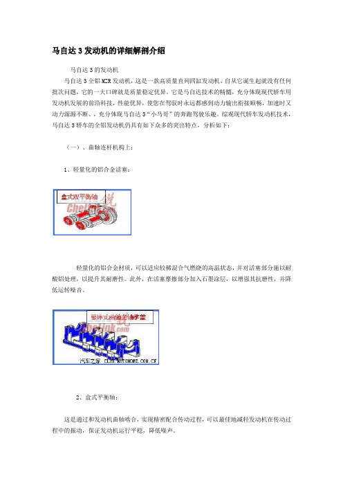
综观现代轿车发动机技术,马自达3轿车的全铝发动机仍具有如下众多的突出特点,分析如下:(一)、曲轴连杆机构上:1、轻量化的铝合金活塞:轻量化的铝合金材质,可以适应较稀混合气燃烧的高温状态,并对活塞部分施以耐酸铝处理,以提升其耐磨性。
此外,在活塞摩擦部分加入石墨涂层,以增强其抗磨性,并降低运转噪音。
2、盒式平衡轴:这是通过和发动机曲轴啮合,实现精密配合传动过程,可以最佳地减轻发动机在传动过程中的振动,保证发动机运行平稳,降低噪声。
3、整体式曲轴主轴承盖:整体式的曲轴安装轴瓦,可以理想地保证发动机曲轴的同轴度,安装的精密度,降低发动机的工作噪声,延长曲轴及曲轴瓦使用寿命,也就是延长发动机大修的周期。
轻铝合金发动机,在减轻重量上是非常突出的,有利于增加轿车的加速性能,并且明显地降低燃油经济性。
(二)、配气机构上:可变配气正时PCM的液压控制系统:马自达3轿车上配备的可变配气正时,这种进气门正时控制代表当今轿车进气控制的一大发展趋势,它是利用发动机电脑精准控制的进气控制方式,可以保证发动机在所有工况下都有一个与之相适应的最大的充气效率。
最大进气效率是发动机性能能否发挥出来的最关键因素,所有品牌的发动机进气控制方面都在不遗余力地在保证最大的进气量而在奋斗,马自达3轿车率先给予了可靠地保证。
(三)在进气系统上:1、先进的“3V”结构再加电子节气门(ETC)控制和可变进气控制(S-VT):“3V”结构是马自达轿车在进气系统上所下功力的最大成就,VAD是可变进气道,VIS 是可变进气控制,VTCS是可变涡流控制。
马自达新一代动力传动系统SKY

NwDvl K mM za 同团田 e re e Yr ad iiS f n o I
体 增加 ,导致 气缸 内气体温 度上 E p a r ig C ce u o e n D i n y l。新 欧洲 在排 气端 采用 可变气 门提 升机 构 , r v
。
而4 2 1 — ~ 式排 气管 的优 点是尾 驾 驶 循 环 ) 式 下 实 现 了 与柴 油 车 增 加 了残 留气体 并提 高 了气缸 内的 模
气体温 度 。
干 涉小 ,可 在 中 低 速 区 提 高 扭 相 当的CO2 排放 量 1 0 /m。 3 gk
。
降低 压 缩 比后 ,压 缩结 束 时的 S Y D 有 配备 尿 素S R 选 K — 没 C ( 及 ( 的距离较 远 ,因此要 在启动 后立 择 性 还 原 催 化 剂 ) NOX 氮 氧 化 温度 也会 下降 ,因此 燃料 与空 气混 吸 激 活催化 剂 ,需要 大幅推迟 点火 物 ) 附 还 原 催 化 剂 等 尾 气 后 处 合 的时 间延长 ,从而 可控 制急剧 燃 另一 方面 ,由于排 气 门与催化
目前使 用 的4 发动 机 都 尽量 缸
为了充 分发 挥新 型动 力传动 系 扭 矩 ,从 而 实 现 了 可 在 驾 驶 时降
统的特性 ,马自达还新设计了汽车 低发 动机转速 的 “ o nS e d D w pe”
使催 化剂靠 近发动 机 ,因此一般采
底盘 ,将柴油 车 中的 “ t n a A e z ”级 性能 。具 体 方 法 是 ,将 压 缩 比提 用 可 将 4 管迅 速 汇集 威 1 管 的 根 根
车辆 的 C O 排放 量 降低到 了与 “ 德 高 至 1 1 4: ,通过 可 变气 门提 升机 4 1 — 式排 气 管。不 过 ,这种 类型 的 米欧 ”相 当的水平 。此次 还备有 试 构减 少 了泵 吸损 失 ,从 而减轻 了摩 排气 管会 因尾 气 的干涉而造 成残 留
压燃“黑科技”——解析马自达SKYAVTIVE-X发动机

New Vehicle084在全世界范围内,排放法规愈发严格,所以大部分厂家为了降低整个产品序列的平均油耗纷纷推出了小排量的涡轮增压发动机,2.5L 、3.0L 以上的大排量自然发动机目前在市面上屈指可数。
不过一向素有‘技术宅’之称的马自达绝对是这其中的叛逆者,坚持在自然吸气的路上寻求突破。
国内消费者在昂科赛拉、阿特兹等车型上已经领略到马自达第一代创驰蓝天技术(SkyActive-G )序列下出色的动力和操控性能,而如今它已经进化到了第二代——SkyActive-X 。
这套动力系统在海外版的马自达3和CX-30上率先搭载,很快也将引入国内市场,我们今天就来介绍下马自达这套动力总成的黑科技。
——解析马自达SKYAVTIVE-X 发动机压燃“黑科技”文/王一鸣 设计/邱洪涛085说到SkyActive-X 发动机,它的最大特色是采用了一种名为“SPCCI ”(Spark Controlled Compssion Ignition 火花点火控制压燃点火)的发动机点火技术。
单从结构上看,SPCCI 和采用传统火花塞点燃技术(SI )的发动机并没有结构性的区别,但是借助更高的压缩比和精准的点火控制,可以实现均质压燃(HCCI )和火花塞点燃(SI )之间的无缝切换。
传统汽油机通过火花塞点火,并向整个燃烧室逐步传递;而传统柴油机则通过活塞压缩混合气体并突破燃点,同时快速着火。
马自达SkyActive-X 发动机结合了汽油机和柴油机的优点,大部分中高转速情况下,汽油空气和废气的混合气在燃烧室内均匀燃烧,物质和热量均匀分布,混合更为充分,燃烧更为彻底,不依靠火焰传播燃烧速度更加迅速,而且理论上不会发生扩散。
在发动机低转速和低负载情况下,SPCCI 可以分别利用CI (压燃)和SI (点燃)的方式驱动,在复杂多变的环境下精确控制每个燃烧循环中混合气体的温度和浓度,这两种方式可以取长补短,以达到更快的点火时间和更均匀的燃烧。
[Word]发动机DUALS-VT技术
![[Word]发动机DUALS-VT技术](https://img.taocdn.com/s3/m/2c39b8b6b1717fd5360cba1aa8114431b90d8e8e.png)
Dual S-VT是双可变气门正时控制系统+电子控制节气门提到创驰蓝天发动机,大家的第一印象就是省油,它的特点仅是省油吗?创驰蓝天发动机的开发理念如何来的?创驰蓝天发动机用了哪些技术来实现它的开发目标?创驰蓝天发动机相关的一系列名词是什么意思?创驰蓝天发动机和涡轮增压发动机对比又如何什么是汽油发动机?一般车用发动机分为两种,以汽油(gasoline)为燃料的汽油机和以柴油(diesel)为燃料的柴油机,所以创驰蓝天汽油机称为Skyactiv-G,创驰蓝天柴油机称为Skyactiv-D。
目前,由于油品和政策原因,国内柴油乘用车尚难以普及,Skyactiv-D目前也未引入国内,因此我们研究的重点是Skyactiv-G。
为了便于了解Skyactiv-G的特点,我们先来了解一下汽油发动机的工作原理。
右边图示是一个缸内直喷汽油机的完整工作流程,包括进气、压缩、排气、做功、排气四个行程,活塞上下往复运动,把汽油燃烧的热量转化为驱动汽车奔跑的动能。
PS.:汽油机与柴油机都属于内燃机,即燃料在发动机内部燃烧。
除活塞式的汽油机,马自达独有的转子发动机也是汽油机马自达的目标—探寻理想的发动机虽然汽油机是乘用车使用最早且应用最广泛的发动机,但是它是理想的发动机吗?当然不是,事实上汽油发动机只能够利用燃料30%的能量,另外70%以各种形式被浪费掉。
因此,各大汽车公司都在寻求提升汽油机燃料利用效率的方法,最终出现了两条技术路线,一个就是用涡轮增压,一个就是混合动力。
这两种技术有两个共同点:都在发动机外部寻求较复杂的解决方法;都认为发动机本身没有太多改进的余地。
但是马自达的工程师不这样认为,他们先明确了理想发动机应该具备的三个特征,即高效清洁排放、可靠性,以这三条来衡量,涡轮增压和混合动力都不能算是理想的发动机。
马自达的工程师决定从零开始,从发动机本身寻找改进的方法,找出了发动机内部最基本的可控因素,并对它们逐一改进,最终成功开发出Skyactiv-G,真正拥有高效率、清洁排放和可靠性的理想发动机。
马自达bk bl驾驶感受

马自达bk bl驾驶感受
1、顺滑。
自然吸气的顺滑感,犹如天鹅绒一般顺畅。
目前马自达主打的两款发动机是2.0L和2.5L的创驰蓝天发动机,作为自然吸气界的扛把子,13:1的压缩比带来了出色的性能提升。
这款发动机的特点让大致的驾驶感受会是如此,起步迅猛,中段省油,高转速压榨出高性能。
最近马自达还有新突破,采用了最新的HCCI均质稀薄压燃技术的创驰蓝天发动机,最高压缩比已经达到了逆天的18:1。
2、很稳。
黑科技GVC。
作为弯道之王,马自达驾驶的另一大感受源于弯道的顺畅感,当然最近加入的GVC加速度矢量控制系统起到至关重要的作用,有了这套系统,使得整车在过弯时,四轮会根据路面反馈,及时的调整四轮输出,增大抓地力,从而提升过弯的顺畅度。
3、很拉风,不要问为什么!那一抹骚红的确很吸引人。
整体做工中等偏上,豪华感不高,实用性不错,人机交互系统合理,抬头显示还有待加强,变速箱聪明,同级别最好用没有之一,加四门隔音,整体的噪音相对较高,平时听歌没太大感觉,并不会吵,油耗不高,启停系统比较好用,最起码比迷你的强太多,造型比较符合多数人审美,大灯不错自动调节,全led,顶棚做工档次相对较低,天窗大小比较中庸,后备箱够大,后排空间相对较小,全车175身高妥妥够用,车身偏长四米九,前雷达
好用,影像系统中庸,右前遮阳挡化妆镜盖异响,轮毂大,侧面视觉感受好,但是容易刮破,胎噪相对较大。
总之比较省心,想玩车的时候跑山路不错,满打一圈半,操控舒服,不像日系车的日系车。
cx4(一汽马自达)详细参数

6扬声器
-
高级沙色打孔真皮
○ ○ ○ ○ ○ ○ ○ ○ ○ ○ ○ ○ ○ ○ ○ ○ ○ ○ ○ ○ ○ ○ ○ ○ ○ ○ ○ ○ ○ ○ -
6扬声器
-
高级棕/黑打孔真皮
○ ○ ○ ○ ○ ○ ○ ○ ○ ○ ○ ○ ○ ○ ○ ○ ○ ○ ○ ○ ○ ○ ○ ○ ○ ○ ○ ○ ○ ○ ○ ○ ○ ○
外饰颜色
注: 1、“○”表示配备,“-” 表示不配备。 2、魂动红和珠光白颜色全系车型需在市场指导价基础上加价2000元/台。 3、本清单中所有配置均以实车为准,为不断推动产品技术进步以满足顾客需求和国家相关法律要求等,一汽马自达汽车销售有限公司有权对上述配置、规格等做修改,并不作另行通知。
○ ○ ○ ○ ○ ○ ○
创驰蓝天-发动机 SKYACTIV-G
○ ○ ○ ○ ○ ○ ○ ○ ○ ○ ○ ○ ○ ○ ○ ○ ○ ○ ○ ○ 速度表中置
○ ○ ○ ○ ○ ○ ○ ○ ○ ○ ○ 行车电脑
○ ○ ○ ○ ○ ○ ○ ○ ○ ○ ○ ○ ○ ○ ○
转速表中置
17英寸(225/65R17)
○ ○ ○ ○ ○ ○ ○ ○ ○ ○ ○ ○ ○ ○ ○
Mazda CX-4 参数配置表
2.0L 6MT 2WD 蓝天活力版 规格参数 长×宽×高(mm) 轴距(mm) 前/后轮距(mm) 尺寸参数 前/后悬(mm) 空载最小离地间隙(mm) 最小转弯半径(m) 油箱容积(L) 行李箱容积(L) 质量参数 整车整备质量(kg) 1390 1450 创驰蓝天汽油直喷全铝合金发动机 水冷直列4缸双顶置凸轮轴(DOHC)16气门 13:1超高压缩比 4-2-1加长型排气系统 Dual S-VT双可变气门正时控制系统+电子节气门 1998 13:1 116/6400 202/4000 200 6.4 192 6.3 国V排放标准 风琴式油门踏板 六速手动 93#(北京92#)及以上无铅汽油 风琴式油门踏板 降挡加速开关(Kickdown Switch) "六速手自一体 全速域锁定技术" 高效能宽速域锁止技术 迅捷换挡响应机电一体化模块 车身胶焊工艺 直线、连续化环闭式车身结构 车身冲击力分散引导系统 前、后、侧方超高强度防撞梁 前悬架:麦弗逊式独立悬架,带横向稳定杆 后悬架:E 型多连杆式独立悬架,带横向稳定杆 电动助力转向系统 四轮盘式制动 前置前驱 i-ACTIV AWD 马自达智能四驱系统 前后轮扭矩动态智能分配 (路况/天气/车轮打滑/驾驶意图实时预判) 7.3 6孔高压缸内直喷技术(二级喷射) 高效燃烧设计凹顶活塞+米勒循环 轻量化、低摩擦阻力技术 2488 13:1 141/6100 252/4000 198 7.2 创驰蓝天技术(SKYACTIV TECHNOLOGY) 发动机型式 197 196 5.6 51 400 1545 1560 4633×1840×1535 4633×1840×1530 2700 1584/1586 950/983 191 194 4633×1840×1535 1584/1587 2.0L 6AT 2WD 蓝天活力版 2.0L 6AT 2WD 蓝天活力真皮版 2.0L 6AT 2WD 蓝天品位版 2.0L 6AT 2WD 蓝天领先版 2.5L 6AT AWD 蓝天激情版 2.5L 6AT AWD 蓝天无畏版
汽车新技术论文3000字

汽车新技术论文3000字篇一:汽车新技术论文汽车新技术,汽车发动机、动力传动、悬架、转向、制动、设计方法、新材料等方面,手写10-15页纸。
摘要:报告讲述了汽车发动机、动力传动、悬架、转向、制动、设计方法、新材料等方面的新技术,结合作者自身的经历讲述对这些新技术的看法和思考,让人耳目一新。
关键词:缸内直喷、FSAE比赛、差速器壳体改装、后轮转向、制动减配、新材料污染前言:自1886年“奔驰1号”诞生开始,世界汽车工业已经延续一百多年了,而他的作用也从当初的代步工具逐渐变的多元化。
依我看来现代汽车更像一件融合了高端科技的绝美艺术品。
汽车的出现极大的改变了人们的生活方式,汽车在改变我们的生活,不过它在带给我们极大便利的同时,的确也带来了一些烦恼。
空气污染是否跟汽车尾气排放有关?想必大家对2021年1月中科院关于汽车尾气排放占有率研究的乌龙事件还记忆犹新。
汽车尾气的排放到底占大气污染源的多少我能力有限,真的无法告诉你。
不过眼下很多汽车新技术都是紧紧围绕节能减排和安全舒适这个两个主题诞生的。
各种新技术的应用使现代汽车不断向着节能化、现代化、智能化、信息化的方向发展,新技术的应用更大程度地满足了人类的安全舒适度需求,同时也进一步降低了人类活动对环境的负面影响。
人类的需求带来问题,人类不得不动脑子解决这些问题。
我觉的百度文库里的这句话说得很好——生活就是这样,对任何生活方式的评价都是相对的,没有绝对的好与坏。
这是一种观念,一种态度,更是一种文化。
下面我就正式开始向大家介绍汽车发动机、动力传动、悬架、转向、制动、设计方法、新材料等方面的一些汽车新技术。
一、汽车发动机发动机这玩意是将自然界中的某种能量直接转换成机械能并拖动某些机械来工作的机器。
简单讲发动机就是一个能量转换机构,即将汽油(柴油)的热能,通过在密封气缸内燃烧气体膨胀时,推动活塞做功,转变为机械能,这是发动机最基本原理。
发动机所有结构都是为能量转换服务的,虽然发动机伴随着汽车走过了100多年的历史,无论是在设计上、制造上、工艺上还是在性能上、控制上都有很大的提高,其基本原理仍然未变,这是一个富于创造的时代,那些发动机设计者们,不断地将最新科技与发动机融为一体,把发动机变成一个复杂的机电一体化产品,使发动机性能达到近乎完善的程度,各世界著名汽车厂商也将发动机的性能作为竞争亮点。
马自达CX-5配置表

创驰蓝天-发 动机
SKYACTIVG
发动机技术
Dual S-VT双可变气门正时控制系统+电子控制节气门
燃烧状态发动机电脑实时控制系统
创驰蓝天-发 排量(ml)
1998
2488
动机 压缩比
13:01
SKYACTIV- 最大功率
G
(kW/r/min
114/6000
最大扭矩 (Nm/r/min
200/4000
〇
〇
〇
〇
〇
〇
一键启动系统
〇
〇
〇
〇
〇
〇
〇
智能无钥匙进入系统
—
—
—
—
〇
〇
〇
间歇可调式前后雨刷
〇
〇
〇
〇
〇
〇
〇
雨量感应式智能前雨刷 —
—
—
—
〇
—
〇
方向盘高低前后四向可调 〇
〇
〇
〇
〇
〇
〇
方向盘音响控制
〇
〇
〇
〇
〇
〇
〇
方向盘定速巡航
—
—
—
—
〇
〇
〇
驾驶员侧车窗一触式升降/ 防夹
〇
〇
〇
〇
〇
〇
〇
行李箱遮物帘车门联动与 细网透视设计
最高车速 (km/h)
197
187
180
综合工况油
13:01 144/6100 252/4000
184
耗
7
6.6
6.6
7.4
7.4
7.7
7.5
- 1、下载文档前请自行甄别文档内容的完整性,平台不提供额外的编辑、内容补充、找答案等附加服务。
- 2、"仅部分预览"的文档,不可在线预览部分如存在完整性等问题,可反馈申请退款(可完整预览的文档不适用该条件!)。
- 3、如文档侵犯您的权益,请联系客服反馈,我们会尽快为您处理(人工客服工作时间:9:00-18:30)。
MAZDA SKYACTIV-G 2.0L Gasoline EngineIchiro Hirose, Hidetoshi Kudo, Tatuhiro Kihara, Masanao Yamakawa,Mitsuo HitomiMazda Motor Corporation, Hiroshima, JapanSummaryThe SKYACTIV-G is the first gasoline engine which was developed based on Mazda's long-term vision for technology and the search of internal combustion engineers who are pursuing technologies to develop the ultimate internal combustion engine. This is done with Mazda's aim in mind to achieve a balance between enjoyable driving and environmental performance at the supreme level.The challenging target of 15% torque improvement compared with that of conventional engine was set. This was achieved by solving technological issues towards introduction of extremely high combustion ratio and a 4-2-1 exhaust system.1 IntroductionMazda is aiming at developing the ideal internal combustion engine before we see the complete EV age. We are sure we can contribute to environmental protection primarily by improving the internal combustion engine which will remain mainstream for the automotive powertrain in the mean time. We also believe that the system cost can be reduced by combining the internal combustion engine with the electric devices, which leads to marketability improvement, such as purchasing cost reduction and maintenance cost reduction. Therefore, as you can see from Figure 1, our plan is to upgrade the efficiency of base technologies for the internal combustion engine and others first, combine such technologies with the electric devices as a next step, and then introduce the combined technologies into markets one after another. We call this plan the "Building-Block Strategy".Figure 2 shows our approach toward the ideal internal combustion engine development. We consider that the approach is the same for both gasoline and diesel engines. To be more specific, bringing control factors, such as compression ratio, combustion duration, etc. to the ideal conditions means that the gasoline engine adopts advantages of the diesel engine and vice versa. The SKYACTIV-G, which has been developed based on the above-mentioned long-term technological development strategy, is the new 2.0 liter gasoline engine which will offer driving pleasure to our customers more than ever and also achieves superb environmentally-friendly performance. It is planned that the SKYACTIV-G will be gradually introduced into various markets in 2011 and thereafter.Fig. 1: MAZDA Building-Block StrategyFig. 2: Roadmap for the Ultimate Internal Combustion Engine2 Technological targetAs the first step to bring the gasoline engine closer to the ideal internal combustion engine, the technological targets were set: 15% improvement in the NEDC mode fuel economy and the full load performance respectively, compared with Mazda's existinggasoline engine (Figure 3). The idea behind these was to develop the world-best engine.Fig. 3: Functional TargetIn order to achieve the technological targets, all the controlling factors except for specific heat ratio were upgraded functionally. Considering the cost performance and assuming the natural-aspirated direct-injection engine, it was aimed to improve the compression ratio and pumping loss which were inferior to those of the diesel engine and reduce the mechanical loss further which was superior to that of the diesel engine.In particular, the functional targets were compression ratio increase to world highest 14:1 (@95RON) while keeping the same combustion period, 20% pumping loss reduction, 30% mechanical loss reduction and 10% charging efficiency improvement. Table 1 shows the main specification comparison of the current PFI engine (hereinafter referred to as "base engine") and the SKYACTIV-G.Table 1: Main Specifications3 Fuel Economy3.1 Compression ratioThe world-highest compression ratio of 14:1 was targeted. It is generally known that with only raising the compression ratio strongly, a high fuel consumption improvement cannot be gained. It was identified at the beginning of the development that primary sources for this were long combustion duration and high cooling loss due to quenching of initial flame kernel core, damping of tumble air motion at the top of the piston (Figure 4 & 5).Fig. 4: Effect of compression ratio on Constant Volume=11Fig. 5: Effect of Compression Ratio on In-cylinder FlowIn order to solve this issue, it was a must to balance two conflicting requirements: to form a large cavity while maintaining a high compression ratio. Therefore, basic designs and dimensions such as the bore diameter and the valve angle for intake and exhaust were carefully reviewed.Fig. 6: Requirements for Bore/Stroke SelectionFirst of all, as shown in Figure 6 it was decided to secure the compression ratio of 15 or more for the future. Then the bore diameter was determined to satisfy the peak power requirement with careful consideration of the small bore requirement to reduce surface-volume ratio and the valve diameter requirement. Consequently, the bore diameter was reduced from 87.5mm to 83.5mm. The valve angle was expanded from intake 19 deg./exhaust 20 deg. to intake 22 deg./exhaust 23 deg. The cavity was designed so that the flame should not touch the piston until the flame level reaches 5% MFB from the perspective of cooling loss reduction.Fig. 7: Effect of Cavity Piston on Tumble Ration and Cooling LossAs you can see from Figure 7, this cavity is effective in reducing the cooling loss and increasing tumbling flow. The cooling loss was reduced by 9% while the combustionspeed was increased as shown in Figure 8. As a result (see Figure 9), the new piston improved specific fuel consumption by 2-3% from the original piston. Further the thermal efficiency improvement effect of compression ratio came closer to thetheoretical expectation.Fig. 8: Effect of Piston Shape on Heat Release0%1%2%3%1500rpm/100kPa 1500rpm/262kPa2500rpm/100kPachanging the port angle to be gentler. With this, the combustion speed was increasedas described in Figure 11.Fig. 10:Intake Port Configuration Fig. 11:Effect of Tumble ration on Heat Release Fig. 12:Effect of Tumble ration on Combustion Duration36384042444648501 1.2 1.4 1.6 1.8Tum ble ratio [-]Target 87.5mmbore 83.5mmboreAs a result, a wider overlapping than ever before and a significantly late intake valve close timing were achieved. To be more precise, a dual S-VT (sequential valve timing system) was incorporated. The intake valve timing was set at IVC=110degATDC/EVC=50ATDC (@2000rpm/200kPa). Figure 13-15 show the pumping loss comparison between the base engine and the SKYACTIV-G. The base engine has TSCV (Tumble Swirl Control Valve) and an external EGR. In contrast, the SKYACTIV-G does not have such devices. However, the SKYACTIV-G increased the internal EGR ratio (11% to 18%), achieved intake valve close timing retarded up to 110ATDC and reduced the pumping loss by 20% without any combustion instability.2018161412105060708090100110Intake Valve Close(IVC) Timing [deg CA]40506070809010005101520Exhaust Gas Recirculation ratio [%]3.3.1 Crank/Piston/ConnrodThe diameter of the crank main journal was reduced from =47mm,while the required rigidity was maintained. In addition, the LOC (lubricant oil consumption) performance was enhanced. These improvements made it possible to use the piston ring with the tension lower than that of the current piston ring by 38%.3.3.2 Valve systemThe valve spring weight was reduced by introducing a roller follower and optimizing the cam profiles. For the chain system, the mechanical resistance was reduced due to chain behavior stabilization by reducing the wearing resistance between the high-rigid straight guide and the chain, and dividing and equalizing the load on the levers.3.3.3 Lubrication systemFirst the oil pump capacity was reduced by decreasing the pressure loss in the hydraulic pressure channel and by minimizing the hydraulic pressure requirements for hydraulic pressure-related devices. Then the hydraulic pressure during the partial load operation was reduced by adopting the electrically-controlled variable hydraulic pressure oil pump. The more effects of the variable hydraulic pressure on the fuel economy are seen under the cold condition when the viscosity and resistance are higher.3.3.4 Cooling systemThe water pump unit efficiency was upgraded by a highly effective plastic impeller and reducing the resistance in the cooling channels.Figure 19 indicates the positioning of the SKYACTIV-G in terms of friction loss by comparing with the base engine friction loss measured by a third party (under the condition of 2000rpm and all accessories included) and using the improvement rate which Mazda confirmed. It demonstrates that the SKYACTIV-G is the world's best in terms of the control factor of the friction loss as well.Fig. 17:Examples of Friction Loss ReductionFig. 18:Typical Components for Friction Loss Reduction050100150200100020003000400050006000Engine speed (rpm)F3.4 Fuel economy in vehicle levelThe vehicle fuel economy was measured by using the C/D-class vehicles equipped with the SKYACTIV-G. Figure 20 shows its breakdown. It was verified that the SKYACTIV-G improved the fuel economy in the NEDC by 15%, compared with the current Mazda engine. This is resulted from the fuel economy improvement effects under the hot and steady conditions, such as the above-mentioned high compression ratio with pumping loss reduction (8%) and friction loss reduction (4%). There are other contributors including effects of variable hydraulic pressure under the warm-up condition where hydraulic pressure difference becomes larger, idle engine speed reduction and so on.0%2%4%6%8%10%12%14%16%Compression Ratio and Pumping Loss EffectIdle-Speed Reduction140150160170180190200210TargetBaseInitial statusFull Load Performance improvement0%15%0%15%Current EngineTargetBreakthrough by combustionFig. 22: Toque Recovery Target by Combustion Improvement4.1 Functional target for full load performance improvementRoot cause of the torque decrease are exactly deterioration in knocking resistance and efficiency drop, which resulted from an increase in the pressure and temperature in the cylinder due to the high compression ratio. Therefore, it was focused to reduce the unburned gas temperature in the cylinder at TDC and to improve the combustion duration, referring to characteristics of the DI engine with low compression ratio of 11:1. As shown in Figure 23, the functional target is equivalent to 50 degree C reduction in the gas temperature in the cylinder and reduction in combustion duration by 5 deg.CA (equivalence of approx. 20%) from the initial status of the SKYACTIV-G. In order to meet this functional target, it was focused to improve the combustion system and the exhaust system.302826242220670680690700710720730740750 Unburned gas temperature at TDC (K)Flat piston20BTDC10BTDCTDC 10ATDCCavity pistonFig. 24:Effect of Piston Shape on Flame PropagationFig. 25:Effect of Piston Shape on Heat ReleaseFig. 26:Effect of Piston Shape on Torque4.2.2 Air motion enhancementProgresses were made in the following elements, a) the bore diameter reduction to diminish the cooling loss, and b) the tumble motion enhancement to raise the combustion speed, with a view to knocking resistance enhancement. The long stroke resulting from the bore diameter reduction effectively enhanced the tumble motion. As shown in Figure 27-28, the combined technologies, the tumble motion enhancement and the bore diameter reduction, reduced the combustion duration by 2 deg.CA and improved the torque by 4%.-20020406080100120140-10103050Crank Angle (deg)87.5mm Bore Original int.port83.5mmBore Enhanced int.port4%Fig. 28: Effect of Tumble Ratio on Torque4.2.3 Air-Fuel mixture formation improvementIt was challenged to maximize the charging effect as the combustion system approach toward the gas temperature reduction in the cylinder.In order to efficiently cool down the gas temperature in the cylinder, the latent heat of fuel and multi-hole injector with 6 holes and an excellent mixing characteristic was introduced. Some elements including the fuel spray angle of each cylinder, the spray penetration and the injection ratio for split injection were optimized by utilizing CAE in order to meet various requirements, such as the mixture homogenization for getting charging effect, and the high stratification for catalyst heating up at warming up, which will be touched on later, the oil dilution and the smoke so on.In general, the spray pattern is designed to inject the fuel homogeneously into the cylinder targeting a homogeneous mixture. However,penetration of #1 spray was controlled more to reduce the oil dilution. The spray angle in the horizontal direction for the #1, #2 and #3 sprays in the first and second rows, which play an important role in stratified mixture formation, is designed so that sprayed fuel is captured by the cavity. The spray angle and penetration for the #6 spray in the bottom row is designed to enhance tumble air motion (Figure 29-30).Fig. 29: Basic Spray ConfigurationFig. 30: Visualization Results of In-Cylinder FlowFigure 31-32 indicate differentials in homogenization among three spray patterns. The Layout-A spray pattern, which the SKYACTIV-G adopted, achieved a better homogenization than the other spray patterns and much better than the traditional swirl-type spray patterns.X sprayY spray 060mm20mm 40mm 0 60mm20mm 40mm (i) Layout A (ii) Layout B (iii) Layout CX sprayY spraysFig. 33: Comparison of Mixture HomogeneityLayout B Layout AFig. 36: Comparison of gas temperature distributionThe combustion duration reduction at 4 deg. CA and 10% torque improvement from the initial status were achieved by incorporating these combustion-related technologies. The SKYACTIV-G with high compression ratio of 14 realized the same torque at low engine speed as the current DI with the compression ratio of 11.4.3 Exhaust system upgradeAlthough the torque was improved by 10% by upgrading the combustion system, as indicated in Figure 37, further 8% improvements were required to meet the torque target at low engine speed. To achieve this, it was aimed at improving the exhaustsystem. Full Load Performance improvement 0%15%0%15%Current EngineTargetBreakthroughby exh. systemFig. 37:Target for Exhaust System DevelopmentFigure 38 indicates the relation between the charging efficiency for the residual gas ratio and the gas temperature in the cylinder at TDC based on the CAE analysis. The residual gas ratio for the 4-1 exhaust system, which is the base exhaust system, isapprox. 7%. The charging efficiency is 84%. The temperature in the cylinder is 720K.6080100120140]39[K]4-1CCstatusScavengingFig. 38: Functional Target for Exhaust System DevelopmentIt is required to secure approximately 160kPa boosting pressure @ IVC in order to gain the charging efficiency sufficiently enough to meet the low-end torque target while keeping the same residual gas ratio. However, this was not an option for the SKYACTIV-G because its design concept was naturally aspiration. Therefore, an approach taken was to reduce the residual gas and the temperature in the cylinder by optimizing the use of scavenging effects. As shown in Figure 38, with scavenging effects, the residual gas was reduced by approx. 45% and the temperature in thecylinder was reduced by 39K. As a result, the charging efficiency increased by approx. 9%, which gave a positive outlook toward the low-end torque target achievement.Fig. 39: Basic Concept of Exhaust System DesignIn order to maximize scavenging effects, it was started to develop the 4-2-1 long exhaust system which is almost disappearing from the industry because of emission reasons.First the exhaust manifold basic specification was decided from the aspect of the pressure wave timing control. In order to prevent the exhaust gas from getting into another cylinder during valve overlap, in other words, in order to prevent the residual gas increase in all the engine speed ranges due to the reversal exhaust gas flow, the runner length to the exhaust manifold collector position was set to approx. 600 mm. This contributed to shifting the resonance point of the reverse negative pressure wave at the exhaust manifold collector during valve overlap to the relatively wide ranges of the engine speed (2000/3000/5000 rpm).Then the pipe diameter and shape of exhaust manifold were optimized to maximize the reverse negative pressure. The exhaust manifold pipe inner diameter was set to) of the exhaust pipe.Fig. 40: Basic Concept of Exhaust System DesignSince it was difficult to predict the above-mentioned 3-dimensionnal effect of exhaust manifold on pressure wave characteristics by using CAE, as you can see from Figure 40, the characteristics were optimized through the rig test with which reflection/damping of the impulse acoustic wave was acoustically analyzed. There are high correlation between the rig test result and the actual engine test result.In addition, the blow down timing and the timing of reversed negative wave coming are carefully adjusted in the engine speed range where scavenging effects are expectable by controlling the EVO timing and the IVO timing optimally.The exhaust manifold was designed to be compact and loop-shaped as shown in Figure 41 so that it was installable on 4WD vehicles and small-sized vehicles. As mentioned earlier, the exhaust manifold was developed by optimizing the tube bending radius through the acoustic rig test. It was confirmed that by doing so, the performance equal to that of the straight 4-2-1 exhaust manifold was secured without deteriorating the pressure wave transmission function, which was the basic function for this exhaust manifold.Fig. 41: Final Design of 4-2-1 Exhaust ManifoldOn the other hand, it was clarified that if the piston protruded too much, scavenging effects were spoiled even when the optimized exhaust system was used. Therefore, the piston design was changed as shown in Figure 42 as a result of the bore diameter reduction. The bore diameter decrease made it possible to reduce the piston protrusion height, maintaining the compression ratio. With this, the torque was improved as expected through the use of the scavenging effects.Thanks to the above-mentioned efforts, the charging efficiency was improved by 9% and the torque at the low engine speed was improved by 8%.Fig. 42: Final Design of Piston ShapeThe improvements in the combustion duration and the gas temperature in the cylinder, and the torque improvement effects are put together and shown in Figure 43 & 44. The temperature in the cylinder and the combustion duration which are almost equal to those of the current DI engine (compression ratio of 11:1) were finally achieved. In addition, the charging efficiency was improved as planned. With these technologies, the low-end torque of SKYACTIV-G was finally upgraded by approx. 15 % from the current DI engine, although its compression ratio was 14:1.202224262830670680690700710720730740750Unburned gas temperature at TDC (K)140150160170180190200210IntialStatusTarget2%pistonoptimisation4%Small Bore andAlirMotion opt.3%mixtureoptimization8%ScavengingIntial Status TargetFig. 44: Roadmap to the Low-End Torque TargetThe scavenging effects gained by improving the exhaust manifold design are also gained from the reverse negative pressure wave from the other exhaust components. It is designed to get scavenging effects in the wide range of the engine speed by adjusting resonance point of the reverse negative wave from the pre-silencer to 2500 rpm and that from main silencer to 1500 rpm (Figure 39).The charging efficiency was improved by adjusting the resonance point of intake system is utilized for 2250rpm where no scavenging effects are expected because the reverse positive wave resonances to valve overlap. By this effort, the flat torque curve was developed in all over engine speed range.It was also verified that the torque drop sensitivity to noise factors, such as intake air temperature, hydraulic temperature, fuel octane value, etc., was equivalent to that of existing engines.As the vehicle models which the SKYACTIV-G will be installed on will commonize the locations and functions of all the intake/exhaust system components which have impacts on torque, it is expected that all the vehicle models will exhibit almost the same torque characteristics.Through the above-mentioned efforts, the technical targets were met: 15% improvements in the fuel economy and the power performance respectively, compared with those of the current engine.The improvements of the SKYACTIV-G fuel economy and power performance under full load operation are shown in Figure 45. The specific fuel economy achieves the same level as existing Mazda diesel engines. Figure 45also shows the positioning of BSFC of SKYACTIV-G by using the base engine's specific fuel consumption measured by the third party and BSFC improvement ratio in the SKYACTIV-Gmeasured in Mazda (absolute BSFC value is just reference). The SKYACTIV-G demonstrates far better fuel consumption than other stoichiometric combustion engines. It can be said that the SKYACTIV-G stands at the world-best level. Further more, the SKYACTIV-G is foremost level in the low-end torque among the existing engines. The max. torque and max. power also stand at the top level. Full Load Performance improvement 0%15%0%15%Current Engine30032034036038040042044046048050050010001500200025003000Engine diplacement (cc)Base engine (measured by 3rd party)15%Positioning of SKYACTIV-G SKYA CTIV-GenginScatter band measured by 3rd PartyFig. 45:Positioning of SKYACTIV-G 2.0L5 Other technical issues to be overcomeAs mentioned earlier, the higher compression ratio and the 4-2-1 exhaust system were incorporated as enablers to improve the fuel economy and low-end torque. There were various technical issues that to be overcome to achieve the development goals. One was the pre-ignition control technology development for high compression ratio. The other was the emission reduction technology development for the 4-2-1 exhaust system. How they were solved will be described next.5.1 Pre-ignition controlThe pre-ignition referred here is auto-ignition of the mixture caused by high pressure and temperature in the cylinder, not the pre-ignition caused by heat spot such as high-temperature spark plug. The heat-spot pre-ignition tends to occur in the high engine speed range easily. While the auto-ignition tends to occur at the low speed where the mixture is compressed for a longer time.As existing engines with the low compression ratio have enough margins from the pre-ignition limit, so far, it is not needed to worry about the robustness against the pre-ignition so much. However, the high compression ratio introduction surely raises possible risks of pre-ignition because the temperature and the pressure in the cylinder significantly increase.In order to prevent abnormal combustions including pre-ignition even under the conditions with considering the effect of multiple noise factors, such as compression ratio raised by carbon deposit or various environmental and driving conditions on pre-ignition limit, the development was proceeded by taking three approaches below.5.1.1 Sensitivity to pre-ignitionSensitivity of various noise factors to pre-ignition was examined. Figure 46 indicate that pre-ignition tends to occur when the engine speed is lower and the intake air temp./water temp. are higher and that it tends to take place more frequently when relative air-fuel ratio(AFR) is aroundFig. 46: Pre-ignition Sensitivity of Several Noise FactorsFigure 47 illustrates the effects of split injection on pre-ignition under the conditions offull load andFig. 47: Effect of Split Injection on Pre-ignitionFigure 48 demonstrates the pre-ignition robustness of SKYACTIV-G under multiple noise conditions. There are sufficient margins even with cam timing fully optimized for best torque under the nominal specifications and standard environmental conditions. However, considering the compression ratio increase due to carbon deposits and the upper limits of the temperature and the octane values so on, there are no more margins left. This indicates that the pre-ignition could occur under worst case.CompressionRationominal (14.0)nominal (14.0)nominal (14.0)nominal (14.0)worst (15.4)worst (15.4)FuelNominal 95RON 95RON 95RON 95RON 93RON worst 91RON Intake air temp.Normal(255858100100100)Normal(90100110110110Preignition MarginePreignition Limit Calibrated IVC for Best TorqueIVC controllable rangeAFR controllable rangeFig. 48:Robustness for Pre-ignitionOn the other hand, there is the pre-ignition controllable range by late IVC controlling and rich AFR operation. Please look at the right side of Figure 48.As this controllable range makes it possible to achieve the effective compression ratio which is below the pre-ignition limit even under the worst condition, pre-ignition can be prevented under any conditions as long as the pre-ignition limit is predicted in response to environment changes. The pre-ignition prediction model was developed for this reason.5.1.2 Pre-ignition prediction technologyFigure 49 shows the relation between the initial combustion position (corresponding MBF 10%) and the heat release under various engine operational conditions. The stronger the pre-ignition is, the earlier the initial combustion is. As a result, there is tendency that more heat is released. If it is possible to predict the combustion cycle where the MBF 10% is positioned at 25deg.BTDC, early signs of pre-ignition can be grasped without fail.Fig. 49: Correlation Between Predicted and Measured Pre-ignition Limit Therefore, the mean effective compression ratio where MBF10% was positioned at 25deg.BTDC was defined as the pre-ignition limit. As shown in Figure 50, Liven-Wood integral formula was used to clarify the relation between the temperature and the pressure in the cylinder which reaches the condition of pre-ignition limit. Based on this study, pre-ignition limit was described as the mean effective compression ratio under the ambient temperature condition (temperature, ambient temperature, coolant temperature etc. which can be measured by sensors existing in the engine.Fig. 50: Correlation Between Initial Combustion Position and Heat ReleaseFigure 51 indicates the correlation between the pre-ignition limit predicted based on the above formula and the measured pre-ignition limit under various conditions. They are in line with each other within +/- 0.2 of the mean effective compression ratio.Fig. 51: Ionization Current Sensor System for Pre-Ignition DetectionAs shown in Figure 47, the engine normally has enough safety against the pre-ignition limit and operates based on the IVC timing which was determined by the fuel economy/power performance requirements. However, when the intake air or hydraulic oil temperature increases extraordinary, IVC is retarded based on the pre-ignition limit predication calculated according to the above formula. With the help of。