Air flow and thermal efficiency characteristics in solar chimneys and Trombe Walls
燃气轮机专业英语
燃气轮机专业英语Gas turbines are the powerhouse of modern industry, converting fuel into mechanical energy with remarkable efficiency.These machines, with their intricate blades and high-pressure combustion chambers, are a marvel of engineering. They are not only found in power plants but also in aviation, where they propel aircraft at incredible speeds.The language of gas turbine engineering is a specialized field, filled with technical jargon that can be daunting to newcomers. Terms like "combustion efficiency," "thermal cycle," and "axial-flow compressor" are common in the professional lexicon.Understanding the components and their functions is crucial. For instance, the compressor section is responsible for pressurizing the incoming air, while the turbine section extracts energy from the expanding gases to drive the generator.Maintenance is key to the longevity and performance of a gas turbine. Regular inspections, monitoring of emissions, and balancing of the rotating assembly ensure optimal operation and compliance with environmental regulations.The future of gas turbines looks promising withadvancements in materials science, leading to lighter, more durable components. Innovations in cooling techniques also allow for higher operating temperatures, enhancing power output.In summary, the professional English of gas turbines is a language of precision and power, essential for anyone working in the field of energy production and mechanical engineering.。
短路电流换路产生的直流分量问题分析

短路电流换路产生的直流分量问题分析吴建云【摘要】针对宁夏电网发生的一起罕见的因短路电流换路产生直流分量导致开关分闸失败的事故案例,对目前电网继电保护配置和重合闸方式进行深入分析,提出了调整线路重合闸方式的解决方案,并在宁夏电网中进行应用.应用结果表明:该方法有效解决了因短路电流换路产生的直流分量问题.【期刊名称】《宁夏电力》【年(卷),期】2017(000)005【总页数】6页(P55-59,63)【关键词】短路电流;直流分量;分闸失败;重合闸【作者】吴建云【作者单位】国网宁夏电力公司电力调度控制中心,宁夏银川, 750001【正文语种】中文【中图分类】TM773目前,国内220 kV及以上线路均采用单相重合闸方式,固定时间无检定重合,经过多年运行,该方式在保障电网安全供电和可靠运行发挥了重要作用,但随着电网规模不断扩大,短路容量不断增大,直流分量对电网的影响日益突出[1]。
2016年5月,宁夏电网发生一起因线路两侧系统短路容量强弱相差较大,开关重合时间不一致造成换路产生的直流分量问题,直流分量较大造成断路器无法灭弧,开关分闸失败,故障由母线失灵保护动作切除,事故造成开关机构损坏,故障范围扩大,对电网造成较大影响。
2016年5 月,宁夏电网发生一起罕见的因短路电流换路引起的直流分量问题,事故造成开关损坏,事故范围扩大。
故障发生前系统运行方式如图1所示,±660kV银东直流额定输送功率为4 GW,京能电厂装机容量为1.32 GW,京川I、II线线路配置RCS-931BM、CSC-103C保护,银川东换流站7531、7530、7532成串运行,京能电厂侧7521、7520、7522成串运行,边开关重合闸时间为0.6 s,中开关重合闸时间为1.2 s。
事故起因为银川东换流站7530开关B相靠近Ⅰ母线侧CT下端盆式绝缘子对地放电,由于故障点位于银川东换流站7530断路器B相靠近Ⅰ母线侧,7530开关CT布置于开关断口两侧,因此故障点在川京Ⅱ线和川灵Ⅱ线线路保护范围内,750 kV川京Ⅱ线和川灵Ⅱ线两套线路差动保护均动作跳开线路两侧故障相,经过0.6 s左右延时后,两侧线路对应边开关重合于永久故障,线路保护加速段动作,跳开川京Ⅱ线和川灵Ⅱ线两侧对应的边开关与中开关,在川京Ⅱ线7522开关重合于永久故障时刻,线路保护在加速段动作跳开7522开关时,由于7522开关失灵,最终引起京能电厂侧750 kVⅡ母失灵出口跳开Ⅱ母所有连接开关,切除故障。
航空发动机专业英语之空气动力学

Introduced how to reduce the impact of emissions on aircraft performance and meet environmental regulations by optimizing exhaust emission design and control technologies.
With the continuous improvement of aircraft performance, the aerodynamic design of aircraft engines is affecting more string requirements, including higher take off and landing speeds, longer flight distances, and more complex flight conditions
Detailed description
Definition and Concepts
Understanding the characteristics and classification of fluids helps to gain a deeper understanding of the working principles of aircraft engines.
Air inlet aerodynamics
Explored the effects of aerodynamic phenomena in combustion chambers on combustion efficiency and emissions, including flame propagation speed, combustion stability, and combustion chamber outlet temperature distribution.
ASHRAE美国采暖、制冷与空调工程师学会关于数据中心温度和湿度限制的开创性改变

ASHRAE’s Groundbreaking EnvironmentalClass ChangesClass ChangesPresented by Don Beaty, DLB Associates©ASHRAE 2011Opening CommentsTwo concerns of many data center operators are:f d1)Did I cause an expensive outage?2)Did I void a warranty on expensive equipment?In 2004, ASHRAE TC 9.9 standardized data center temperature and humidity.Created a common set of vendor neutral environmental guidelines that the ITd f d l i l id li h h OEMs would agree did NOT violate their warranties.In 2008, ASHRAE TC 9.9, 20°C to 25°C range became 18°C to 27°C while still being within warranty requirements.In 2011, White Paper provides scenarios for ranges as wide as 5°C to 45°C.©ASHRAE 2011AgendaPart 1 –ITE Environment(Envelopes, Classes & Specifications)(f) Part 2 –Use & Application Guidance for New ASHRAE DataP t2U&A li ti G id f N ASHRAE D t Center Classes©ASHRAE 2011Part 1 –ITE Environment©ASHRAE 2011©ASHRAE 2011©ASHRAE 2011ITE Environment –Envelope DefinitionsFor optimal IT equipment reliability and longevity, conditions should bei l i li bili d l i di i h ld b within the recommended envelope. However, occasional, short-term excursions into the allowable envelope MAY be acceptable.excursions into the allowable envelope MAY be acceptable.Recommended–The purpose of the recommended envelope is to give guidance to data center operators on maintaining high reliability and also id d i i i hi h li bili d l operating their data centers in the most energy efficient manner.recommended envelope is based on IT OEM’s expert knowledge ofThe recommended envelope is based on IT OEM s expert knowledge of server power consumption, reliability & performance vs. ambient temp.Allowable–The allowable envelope is where the IT manufacturers test their ll bl h ll bl l i h h f h i equipment in order to verify that the equipment will function within those environmental boundaries.environmental boundaries.©ASHRAE 2011Criteria20042008Low End Temp.20°C18°CHigh End Temp.25°C27°CLow End Moisture40% RH 5.5°C DPHigh End Moisture55% RH60% RH & 15°C DP©ASHRAE 2011Criteria20042008Low End Temp.20°C18°CHigh End Temp.25°C27°CLow End Moisture40% RH 5.5°C DPHigh End Moisture55% RH60% RH & 15°C DP©ASHRAE 2011ITE Environment –New Data Center ClassesPreviously there were four classes (Class 1 through 4) total.i l h f l(l h h)lTwo of the old Classes were specifically for data centers (Class 1 & 2).Two of the old Classes were specifically for data centers(Class1&2).The naming conventions have now been updated; the old Classes 1, 2, 3 and di l d2d4 directly mapped to A1, A2, B and C.Two new data center classes have been introduced: A3 and A4.Two new data center classes have been introduced:A3and A4©ASHRAE 2011ITE Environment –New Data Center ClassesPreviously there were four data center classes (Class 1 through 4). Two ofi l h f d l(l h h)f the four classes applied to ITE used in data center applications (Class 1 & 2).The new environmental guidelines have more data center classes to accommodate different applications and priorities of ITE operation.This is critical because a single data center class forces a single optimization whereas each data center needs to be optimized based on the operator s whereas each data center needs to be optimized based on the operator’s own criteria (e.g. fulltime economizer use vs. maximum reliability).The naming conventions have now been updated to better delineate theh i i h b d d b d li h types of IT equipment. The old and new classes are now specified differently with the previous Classes1,2,3and4directly mapped to A1,A2,B andwith the previous Classes 1, 2, 3 and 4 directly mapped to A1, A2, B and C.Two new data center classes have been introduced: A3 and A4.©ASHRAE 2011Criteria20042008Low End Temp.20°C18°CHigh End Temp.25°C27°CLow End Moisture40% RH 5.5°C DPHigh End Moisture55% RH60% RH & 15°C DP©ASHRAE 2011Two NEW data center classeshave now been defined (A3,A4) with expanded allowableA4)with expanded allowableenvelopes.The envelopes for newThe envelopes for newClasses A1 and A2 areEXACTLY the SAME asprevious Classes 1 & 2The recommendedenvelope isEXACTLYthe SAME.the SAME©ASHRAE 2011ITE Environment –New Equip. Environment Specifications Table (Partial)©ASHRAE 2011Part 2 Use and ApplicationPart2–Use and Application Guidance for New ASHRAE DataCenter Classes©ASHRAE 20112011 Thermal Guidelines –Operating Envelopeh d i i i i l l i i bl bl d The data center optimization is a complex multi-variable problem and requires a detailed engineering evaluation to be successful.ITE Allowable EnvelopeITE CorrosionITE Acoustical NoiseITE ITE CostITE Power PerformanceITE AirflowOperating ITE ITE PowerDatacenter operational EnvelopeITE Reliabilityoperational knowledge©ASHRAE 2011Use & Application Guidance for New ASHRAE Data Center Classes S d biServer Power Trend vs. Ambient Temperature Airflow and power increase with temperature.Airflow PowerPower required increases to the cube of fan speed (rpm)©ASHRAE 2011Whiteboard©ASHRAE 2011Server Reliability Trend vs. Ambient TemperatureS li bili d biThe hardware failure rate within a given data center will be determined by:1)The local climate2)Type of economizationType of economization3)Facility setpoint/ operation.For the following example, the data is based on:1)air-side economizer (with an assumed 1.5°C system gain))i id i(i h d°i)2)Internal data center temp. is allowed to vary with ambient temp.3)Air mixing occurs to maintain a minimum data center temp of 15°C.©ASHRAE 2011Server Reliability Trend vs. Ambient Temperature (cont.)S li bili d bi()2010 dry bulb temp for Shanghai with air mixing to maintain 15°C min. temp.©ASHRAE 2011Assumes continuous (7 x 24 x 365) operation with Dry Bulb Temp. at ITE inlet. Assumes continuous(7x24x365)operation with Dry Bulb Temp at ITE inlet©ASHRAE 2011Server Reliability Trend vs.Ambient Temperature Server Reliability Trend vs. Ambient Temperature (cont.)Shanghai Net X-Factor across the whole year.IT hardware failure in Hong Kong with a variable data centertemperature is only 5.9% higher than if the data center wasoperating at a tightly controlled temperature of 20°C ©ASHRAE 2011operating at a tightly controlled temperature of 20C.S li bili d bi()Server Reliability Trend vs. Ambient Temperature (cont.)Average Net Failure Rate Projections for Air-side Economization (World Cities)©ASHRAE 2011S li bili d bi()Server Reliability Trend vs. Ambient Temperature(cont.)Chiller Hours Per Year for Air-side Economization (World Cities)©ASHRAE 2011©ASHRAE 2011Use & Application Guide for New Data Center Classes S li bili C i iServer Reliability vs. Contamination Particulate and gaseous contamination becomes a more important consideration when there is an increased use of economizer systems.consideration when there is an increased use of economizer systems.The air quality and building materials should be checked carefully for sources of pollution & particulates and additional filtration should be added to p p remove gaseous pollution and particulates, if needed.Products ofC b ti Pollen Dirt Smoke©ASHRAE 2011CombustionSHOW & TELL©ASHRAE 2011Closing CommentsPower Usage Effectiveness (PUE) has now become the default metric toff i()h b h d f l i measure data center efficiency.To enable improved PUE capability TC 9.9 has created additional environmental classes for data centers with expanded ALLOWABLE temperature and humidity ranges.temperature and humidity rangesClasses A3 and A4 have been added primarily for facilities wishing to avoid the capital expense of compressor based cooling.Expanding the capability of IT equipment to meet wider environmental Expanding the capability of IT equipment to meet wider environmental requirements can change reliability, power consumption & performance. ASHRAE are providing guidance for operators to be able to understand the ASHRAE are providing guidance for operators to be able to understand the magnitude of the change as applied to their particular climate.©ASHRAE 2011TC 9.9 Datacom Book Series1Thermal Guidelines for Data Processing Environments 3rd Edition (coming soon)1.Thermal Guidelines for Data Processing Environments 3Edition (coming soon)2.Datacom Equipment Power Trends & Cooling Applications (2005)3.Design Considerations for Datacom Equipment Centers (2006)4.Liquid Cooling Guidelines for Datacom Equipment Centers (2006)5.Structural & Vibration Guidelines for Datacom Equipment Centers (2008)6Best Practices for Datacom Facility Energy Efficiency (2008)6.Best Practices for Datacom Facility Energy Efficiency (2008)7.High Density Data Centers –Case Studies & Best Practices (2008)8.Particulate & Gaseous Contamination in Datacom Environments (2009)9.Real-Time Energy Consumption Measurements in Data Centers (2009)10.Green Tips for Data Centers (2011)©ASHRAE 2011Contact InformationDon BeatyDon BeatyDLB AssociatesTel: +1 (732) 910-1300Email: dbeaty@il db@dlb iASHRAE TC 9.9 Website©ASHRAE 2011END OF SLIDES©ASHRAE 201131。
不同常压流化床煤气化方案的模型预测__模型预测及分析

第32卷2004年第3期6 月燃 料 化 学 学 报JOURNAL OF FU EL CHEM ISTRY AND TECHNOLOGYVol 32 No 3Jun 2004文章编号:0253 2409(2004)03 0292 05收稿日期:2003 06 23;修回日期:2004 03 18基金项目:国家重点基础研究发展规划项目(G1999022105)作者简介:吴学成(1978 ),男,浙江长兴人,博士研究生,热能工程专业。
E mail:fencewu@不同常压流化床煤气化方案的模型预测.模型预测及分析吴学成,王勤辉,骆仲泱,方梦祥,岑可法(浙江大学热能工程研究所,能源洁净利用与环境工程教育部重点实验室,浙江杭州 310027)摘 要:利用已建立的流化床煤气化模型系统地研究了不同气化方案下的流化床煤气化性能,包括空气气化、空气 蒸气气化、空气 二氧化碳气化、氧气 水蒸气气化、氧气 二氧化碳气化5个气化方案,结果表明:空气 水蒸气和氧气 水蒸气方案具有较优的气化效率和较高的煤气品质,氧气 蒸气气化方案在煤气组分、气化效率和热效率等方面比空气 蒸气气化方案更具优势。
关键词:煤气化;流化床;气化模型;模型预测中图分类号:TQ541 文献标识码:A为了评价常压流化床煤气化中各种气化方案的优劣,吴学成等[1]从化学动力学[2,3]角度并结合化学平衡[4,5]建立了流化床煤气化模型,并通过对文献报道的几个流化床气化实际工况进行计算预测。
计算数据和实测数据比较吻合,表明模型有较好的可信度。
在此基础上,本文利用该模型系统地研究了不同气化方案对常压流化床气化性能的影响,考察了空气,空气 二氧化碳,空气 水蒸气,氧气 二氧化碳,氧气 水蒸气等5种气化方案下流化床的煤气化过程、煤气组分和气化效率,并进行了比较,为实验及工业气化炉设计提供理论基础。
1 气化方案模型预测为方便计算,计算基准参数见表1(取自文献[1]表2中的工况 ),气化系统散热损失假定为3.0%,各种气化方案基准工况的选取参考了部分文献试验报道以及理论计算。
LOW-E 玻璃钢化(英文)
INTRODUCTION
I shall use the case of tempering Low-E glass for the purpose of describing the application of convection in a demanding process for a product growing in popularity.
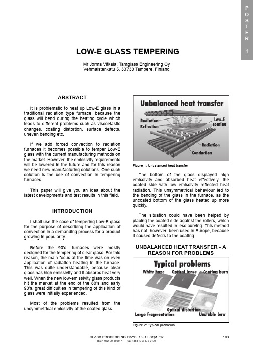
Most of the problems resulted from the unsymmetrical emissivity of the coated glass.
Figure 1: Unbalanced heat transfer
The bottom of the glass displayed high emissivity and absorbed heat effectively, the coated side with low emissivity reflected heat radiation. This unsymmetrical behaviour led to the bending of the glass in the furnace, as the uncoated bottom of the glass heated up more quickly.
where T is the temperature of the glass, t and x stand for time and space and a is the thermal diffusivity.
模拟建筑英语作文模板及范文
模拟建筑英语作文模板及范文英文回答:Architecture Simulation: A Comprehensive Guide。
Architecture simulation plays a crucial role in modern architectural design and construction. It allows architects and engineers to create virtual models of buildings and environments, enabling them to analyze and test different design options, optimize building performance, and identify potential problems before construction begins.Components of Architecture Simulation。
3D modeling: Creating detailed digital representations of buildings and their surroundings.Physics engines: Simulating the physical behavior of buildings, including structural integrity, wind loads, and thermal performance.Occupancy simulation: Modeling human interactionwithin buildings, including crowd movement, space utilization, and behavioral patterns.Building information modeling (BIM): Integrating information from multiple disciplines into a single digital model for comprehensive building design and analysis.Types of Architecture Simulation。
air conditioning 空调

air conditioning 空调air-air heat pump 气-气热泵air-blower 鼓风机air-cooling coil空气冷却盘管air-flow 空气流量airflow meter 空气流量表air-free 真空的air-meter 风速计air-vent 排气口、通风口airborne pollution大气污染airness 通风airway 风道专业名词缩写Air condition空调Air compressor空气压缩机Air condenser空气冷凝器Air cooler 空气冷却器EER (energy efficiency ratio)能效比COP (coefficient of performance)性能系数IAQ (Indoor Air Quality)室内空气品质IEQ (Indoor Environmental Quality)GSHP(Ground source heat pump)地源热泵PCM(Phase change material)相变材料Theory(Fundamentals of HVAC)Thermodynamics and Refrigeration Cycles (热力学和制冷循环)Fluid mechanics (流体力学)Heat Transfer (传热)Mass Transfer(传质学)Psychrometrics (焓湿学)Emphasis: English to ChineseTheory(Fundamentals of HVAC)Thermodynamics and Refrigeration Cycles (热力学和制冷循环)Fluid mechanics (流体力学)Heat Transfer (传热)Mass Transfer(传质学)Psychrometrics (焓湿学)Emphasis: English to ChineseTheory(Fundamentals of HVAC)Thermodynamics and Refrigeration Cycles (热力学和制冷循环)Fluid mechanics (流体力学)Heat Transfer (传热)Mass Transfer(传质学)Psychrometrics (焓湿学)Emphasis: English to ChineseTheory(Fundamentals of HVAC)Thermodynamics and Refrigeration Cycles (热力学和制冷循环)Fluid mechanics (流体力学)Heat Transfer (传热)Mass Transfer(传质学)Psychrometrics (焓湿学)Emphasis: English to ChineseTheory(Fundamentals of HVAC)Thermodynamics and Refrigeration Cycles (热力学和制冷循环)Fluid mechanics (流体力学)Heat Transfer (传热)Mass Transfer(传质学)Psychrometrics (焓湿学)Emphasis: English to ChineseTheory(Fundamentals of HVAC)Thermodynamics and Refrigeration Cycles (热力学和制冷循环)Fluid mechanics (流体力学)Heat Transfer (传热)Mass Transfer(传质学)Psychrometrics (焓湿学)Emphasis: English to ChineseTheory(Fundamentals of HVAC)Thermodynamics and Refrigeration Cycles (热力学和制冷循环)Fluid mechanics (流体力学)Heat Transfer (传热)Mass Transfer(传质学)Psychrometrics (焓湿学)Emphasis: English to ChineseTheory(Fundamentals of HVAC)Thermodynamics and Refrigeration Cycles (热力学和制冷循环)Fluid mechanics (流体力学)Heat Transfer (传热)Mass Transfer(传质学)Psychrometrics (焓湿学)Emphasis: English to ChineseEngineering InformationThermal Comfort (热舒适)Air Contaminant (空气污染物)Emphasis: Chinese to English; AbstractHVAC systems and EquipmentCentral cooling and Heating (集中供冷、供热)Decentralized Cooling and Heating(非集中式供冷、供热)Air-cooling and Dehumidifying coils (冷却去湿盘管)Air cleaners for particulate contaminants (可吸入颗粒污染物空气净化器)Unitary Air Conditioners and Unitary Heat Pumps (单元式空调机组和热泵)Emphasis: Reading Comprehension;Potential energy (势能)Thermal energy (内能)Kinetic energy (动能)Chemical energy (化学能)Nuclear (atomic) energy (原子能)Mechanical or shaft work (W)(机械功或轴功)Flow work(流动功)Saturated liquid (饱和液体)If a substance exists as liquid at the saturation temperature and pressure, it is called saturated liquid. Subcooled liquid (过冷液体)Compressed liquid (压缩液体)Saturated vapor (饱和蒸汽)Dry saturated vapor (干饱和蒸汽)Superheated vapor (过热蒸汽)Quality 干度Thermodynamics (热力学)Entropy (熵);enthalpy (焓)Internal energy (内能)Potential energy (势能)Kinetic energy (动能)Saturated liquid (饱和液体)Subcooled liquid (过冷液体)Saturated vapor (饱和蒸汽)Super-heated vapor (过热蒸汽)Law of the conservation of energy (能量守恒定律)First law of thermodynamics (热力学第一定律)Second law of thermodynamics (热力学第二定律)Calculating Thermodynamic PropertiesBubble point 气泡点,始沸点Bubble point curve 气泡曲线Dew point 露点Zeotrope 非共沸点Azeotropic 共沸点Refrigeration cycle (制冷循环)Coefficient of Performance (性能系数)Refrigerating efficiency(制冷效率)Isentropic expansion (等熵膨胀)Isentropic compression(等熵压缩)Isothermal compression(等温压缩)Isobaric (等压)Equation of state (状态方程)Expansion valve (膨胀阀Fluid mechanics (流体力学)Shearing stress (切应力)Laminar flow (层流)Turbulence (紊流)Density(密度)Viscosity (粘度)absolute viscosity or dynamic viscosity(动力粘度); kinematic viscosity(运动粘度)Generalized Bernoulli equation (广义伯努利方程)Reynolds number (雷诺数)Boundary layer (边界层)Drag coefficient (阻力系数)Shearing stress (切应力), NKinematic viscosity (运动粘度),m2/sThe ratio of absolute viscosity to density.Velocity gradient (速度梯度)Wall friction (壁面摩擦力)Heat transfer process(传热过程)Steady-State Conduction(稳态导热)Fourier lawOverall heat transfer process(总的传热)Transient heat flow (非稳态传热)Thermal Radiation (热辐射)Heat transfer (传热)Thermal conduction (热传导)Thermal convection (热对流)Thermal radiation (辐射)Natural (free) convection (自然对流)Forced convection (强迫对流)Boundary layer (边界层)Fully developed laminar flow (充分发展的层流流动)Fully developed turbulent flow (充分发展的紊流流动)Laminar sublayer (层流底层)Buffer layer (过渡层, 缓冲层)Turbulent region (紊流区)Thermal resistance in series(串联热阻)Thermal resistance in parallel(并联热阻)In the direction of (沿…方向)Be termed (被称为)Be designated as (被定义为)Thermal circuit (热力循环)Overall heat transfer coefficient (总传热系数) Logarithmic mean temperature difference(对数平均温差法)效率,效能) NTU (Number of heat exchanger heat Transfer Unit, 传热单元)Capacity Rate Ratio z (热容比)Parallel flow exchangers (顺流换热器)Counterflow exchangers (逆流换热器)Total rate of energy emission per unit area (单位面积总辐射力)Monochromatic emissive power (单色辐射力)Wien’s displacement law (维恩位移定律)Nonbalck (非黑体)Hemispherical emittance (半球辐射率)Gray(灰体)Absorptance (吸收率)Transmittance (透射率)Reflectance (反射率)Kirchhoff’s law(基尔霍夫定律)Lambert’s law(兰贝特定律)Diffuse radiation (漫辐射)Angle factor (角系数)Nonabsorbing media (非吸收性介质)Thermal circuit (热力循环)Overall heat transfer coefficient (总传热系数) Logarithmic mean temperature difference(对数平均温差法)效率,效能) NTU (Number of heat exchanger heat Transfer Unit, 传热单元)Capacity Rate Ratio z (热容比)Parallel flow exchangers (顺流换热器)Counterflow exchangers (逆流换热器) concentration gradient (浓度梯度)Molecular diffusion (分子扩散)Fick’s law (菲克定律)Mass diffusivity (扩散系数)Mass transfer coefficient (传质系数)Mass/Molar flux (质量/物质的量通量)Significant error (显著误差)Moist air (湿空气)Partial pressure gradient (分压力梯度)Convection of mass (对流传质)Lewis Relation (刘易斯关系)air washer(空气洗涤器)cooling tower (冷却塔)dehumidifying coil(除湿盘管)liquid absorbent(液体吸收剂)evaporative condenser(蒸发式冷凝器)dilute component(稀释成分)a binary gas mixture(二元气体混合物)random molecular motion(分子无规则运动)Stagnant fluids(停滞流体)nonpolar gas(非极性气体)mass transfer:Molecular diffusion(分子扩散)Convective mass transfer(对流传质)Atmospheric air (大气)Moist air (湿空气)Dry air (干空气)Thermodynamic temperature scale (热力学温标)Water at saturation (饱和水)Liquid water(液态水)barometric pressure (大气压力)troposphere(对流层)stratosphere(同温层、平流层)thermodynamic temperature scale(热力学温标)Humidity ratio (含湿量)Saturation humidity ratio (饱和含湿量)Specific humidity (比湿度)Degree of saturation (饱和度)Relative humidity (相对湿度)absolute humidity (绝对湿度)Dew-point temperature (露点温度)Thermodynamic wet-bulb temperature (热力学湿球温度)psychrometer 温度计Composition of Dry and Moist Air (干空气和湿空气组成成分)United States Standard Atmosphere (美国大气标准)Thermodynamic Properties of Moist Air (湿空气热力学性质)Thermodynamic Properties of Water at Saturation(饱和水的热力学性质)Humidity Parameters (湿度参数)Thermodynamic wet-bulb Temperature and Dew-point temperature(热力学湿球温度和露点温度)Psychrometric charts(焓湿图)troposphere(对流层)stratosphere(同温层)Absolute humidity (绝对湿度)Saturation humidity ratio (饱和含湿量)Degree of saturation (饱和度)Dew-point temperature (露点温度)Relative humidity (相对湿度)Thermodynamic wet-bulb temperature (热力学湿球温度)Psychrometric charts(焓湿图)energy expenditure(能量消耗)Human Thermoregulation(人体热调节)Energy Balance (能量平衡)Conditions for Thermal Comfort (热舒适状况)Prediction of Thermal Comfort (热舒适的预测)Thermostat setting(温度调节装置)thermoregulation(体温调节)hyperthermia(体温过高)hypothermia(体温过低)hypothalamus (下丘脑)vasodilation (血管舒张)Skin wettedness(皮肤潮湿率)Integral control(积分控制)Sensible heat(显热)Latent heat (潜热)ASHRAE thermal sensation scale(ASHRAE 热感觉指标)Clothing insulation levels(衣服热阻)Predicted mean vote (PMV)index(预期平均评价表)Thermal load(热负荷)Predicted percent dissatisfied (PPD)(预期不满意百分数)Two-Node Model (两节点模型)Skin compartment (皮肤间隔)Adaptive models (自适应模型)Hypothalamus(下丘脑)The metabolic activities(新陈代谢)dissipated(消耗)hyperthermia(体温过高)hypothermia(体温过低Sensible and latent heat losses(显热和潜热损失)heat storage(蓄热)Energy Balance (能量平衡)Conditions for Thermal Comfort (热舒适状况)Prediction of Thermal Comfort (热舒适的预测)Steady-State Energy Balance(稳态能量平衡)Prediction of Thermal Comfort (热舒适的预测)Essential values(基准值)Classification of Air Contaminants(空气污染物分类) Particulate Contaminants(颗粒污染物)Arise from:Wind erosion (风的侵蚀)Sea spray evaporation(海水蒸发)Volcanic eruption(火山喷发)Metabolism or decay of organic matter(有机物质的新陈代谢或腐烂)Human activityElectric power-generating plants(发电厂)Various modes of transportation(各种运输方式) Industrial processesMining(采矿), smelting(冶炼), construction(建筑)Agriculture generateAir Contaminants(空气污染物)helium (氦)particulate(颗粒,微粒)dusts(粉尘)fumes(烟雾、烟尘)mist(轻雾)fogs(雾)smog(烟雾)bioaerosols(生物气溶胶)inhalable(可吸入的)respirable(呼吸性的)anthropogenic (人为的)bacteria(菌)viruses(病毒)fungus(菌类)pollen(花粉)environmental tobacco smoke (环境香烟烟雾,二手烟)inhalable mass(可吸入物)thoracic particle mass(胸部颗粒物)respirable particulate mass (可吸入颗粒物) aerodynamic (equivalent)diameter (空气动力学(当量)直径)Optical particle counters(光学粒子计数器)Minimum efficiency reporting value (最低效率报告值) Condensation nucleus counter (凝结核计数器)Optical density (光密度)Microscope(显微镜)Cascade impactor (分级采样仪)inhalable mass(可吸入物)thoracic particle mass(胸部颗粒物)respirable particulate mass(可吸入颗粒物)An efficiency by mass(质量效率)Suspended particles (悬浮颗粒)Preassessment (预评估)Air sampling(空气取样)Dry filter paper(干滤纸)Glass impingers (玻璃吸收瓶)Slit samples (膜取样)Culture plate impactors (培养皿采样仪)Slit-to-agar samplers(膜-琼脂采样)Filter cassette samplers (过滤盒采样)Data interpretation(数据说明)Redundancy (富裕量)Reliability (可靠性)Flexibility (灵活性)Life cycle analysis (生命周期分析)Construction budget(施工预算)CENTRAL COOLING AND HEATING(集中制冷与供热)DECENTRALIZED COOLING AND HEATING(分散式制冷与供热)AIR-COOLING AND DEHUMIDFYING COILS(空气冷却与除湿盘管)AIR CLEANERS FOR PARTICULATE CONTAMINANTS(颗粒污染物的空气净化器)UNITARY AIR CONDITIONERS AND UNITARY HEAT PUMPS (单元式空调器与热泵)Refrigeration Equipment(制冷设备)Heating Equipment(供热设备)Distribution(输配)Instrumentation (仪表)Space Requirements(空间需求)Central Plant Loads(集中设备负荷)Geothermal (地热)Maintenance and labor costs(维护和劳动成本)Decentralized plant(分散式设备)Boiler(锅炉)Centrifugal refrigeration units(离心式制冷机组)Absorption chillers(吸收式冷水机组)Heat reclaim(热回收)Exhaust gases(废气)Air distribution(气流组织)Ice thermal storage(冰蓄冷)Conventional system(常规系统)Energy penalty=energy loss(能量损失)chilled water (冷冻水)decentralized plant(分散式设备)Boilers(锅炉)absorption chillers (吸收式冷水机组)heat reclaim (热回收)any exhaust gases(废气)ir distribution(气流组织)water and ice thermal storage(冰蓄冷)conventional system(常规系统)he energy penalty(能量损失)reciprocating compressors(活塞式压缩helical rotary compressors(螺杆式压缩机)centrifugal compressors(离心式压缩机)absorption chillers(吸收式制冷机)frequently field assembled(现场组装)air-cooled or evaporative condensers (空气冷却或蒸发式冷凝器)remote installation(远程安装)Air cooled condensers(风冷冷凝器)Evaporative condensers((蒸发式冷凝器)8.2HEATING EQUIPMENTWorking medium(工质)Circulation rate(循环流量)Fire tube boilers(火管锅炉)Water tube boilers(水管锅炉)Cast iron sectional boilers(铸铁组合锅炉)Negative pressure (负压)Positive pressure(正压)Natural draft boiler(自然通风锅炉)Stack(烟道)Chimney(烟囱)Condenser water(冷凝水)Condensate(凝结水)Boiler feed(锅炉供水)Fuel oil(燃料油)Load calculation (负荷计算)Solar radiation (太阳辐射)Thermal equilibrium (热平衡)Conduct heat gain (导热得热)External wall (外墙)Sensible heat (显热)Heat transfer coefficient (传热系数)Shading coefficient (遮阳系数)Latent heat (潜热)Exterior window (外窗)Wind velocity (风速)Wind pressure (风压)Stack effect (烟囱效应)Cooling load (冷负荷)Commercial building (商业建筑)Residential building (居住建筑)System characteristics(系统特征)Economizers(节能装置)Through-the-wall and Window-mounted Air Conditions and Heat Pumps(穿墙式和窗式空调及热泵)Interconnected Room-by-room System(互联的室室系统)heating coil (加热盘管)Cooling coil (冷却盘管)Window air conditioners(窗式空调器)through-the-wall room air conditioners(穿墙式房间空调器)unitary air conditioners (单元式空调器)air-source heat pumps (空气源热泵)water-source heat pumps (水源热泵)Self-contained units(独立式机组)discharge air temperature(排风温度)Air-handling systems(空气处理系统)Self-contained units(独立式机组)outdoor air damper, relief damper, return air damper(室外空气阀、排风阀、回风阀)variable-volume relief fan(变量排风风机)static pressure (静压)dynamic pressure (动压)direct-expansion cooling coil(直接蒸发式表冷器)variable-air-volume (VAV变风量)Packaged terminal air conditioners(组合式末端空调器) ductwork(管道系统)cabinet enclosure(箱体外壳)stack effect(烟囱效应)Hermetic reciprocating compressors(全封闭活塞式压缩机)scroll compressors(涡旋式压缩机)expansion valves(膨胀阀)energy efficiency ratio (coefficient of performance) defrost(除霜)Warm air furnaces (暖风机)Hot water boilers (热水锅炉fire tube boilers(烟管锅炉)water tube boilers(水管锅炉)cast-iron sectional boilers(铸铁模块锅炉)electric boilers(电锅炉)Air handlers (空气处理装置)Field built-up system(现场组合系统)Economic analysis (经济性分析)Air handler(空气处理装置、空调箱)Aqueous glycol(乙二醇水溶液)Barometric pressure(大气压力)Bypass damper(旁通风管)cleanliness(洁净度)Constant pressure expansion valve(恒压膨胀阀)Cross-counterflow(交叉逆流)dehumidify(除湿、减湿)Drain plug(泄水阀)Eliminator plate(挡水板)Throttling vavle(节流阀)Water and Aqueous Glycol Coils (水和乙二醇盘管) Direct-Expansion Coils(直接蒸发盘管)outside diameter(外径)tube spacing ranges(管间距)Water and Aqueous Glycol(乙二醇溶液)CoilsThe capillary tube (毛细管)thermostatic expansion valve(TXV)(热力膨胀阀)General Exhaust (Dilution) Ventilation Systems(全面通风) Local Exhaust Ventilation Systems(局部通风)Fan SelectionHoods (排风罩)Ducts(管道)Air CleanersStacks (烟囱)Make-up Air Systems (补风)Make-up air systems补风系统ventilation system 通风系统emission sources 排放源污染源general exhaust ventilation全面通风dilution ventilation 稀释通风local exhaust ventilation 局部通风number of air changes 换气次数mixing efficiency 混合效率hood排风罩contaminant 污染物make-up air 补充空气air cleaner 空气处理器stacks烟囱static pressure 静压velocity pressure动压axial flow fan 轴流风机centrifugal fan离心风机entry losses 入口损失friction losses摩擦损失precipitator除尘器cyclone 旋风除尘器negative pressure负压positive pressure正压air-handling system 空气处理系统recirculated air(循环风)airborne particles(尘埃粒子)microorganisms(微生物)Air Cleaning Applications (空气净化应用)Mechanisms of Particle collection (除尘机理)Evaluating Air Cleaners (评价空气净化器)Types of Air Cleaners (空气净化器的类型)Filter Types and Their Performance (过滤器的类型及性质)smaller particles, the respirable(可吸入)fraction Electronic air cleaners (静电空气净化器)medium-to high-efficiency filters (中高效过滤器)high-or ultrahigh-efficiency filters(高效或超高效过滤器)Efficiency(效率)Resistance to airflow(气流阻力)Dust-holding capacity(容尘量)Efficiency(效率)Resistance to airflow(气流阻力)Dust-holding capacity(容尘量)Arrestance(捕集率)ASHRAE Atmospheric Dust-Spot Efficiency(ASHRAE大气比色效率)Fractional Efficiency or Penetration (分级效率或穿透率)Efficiency by Particle Size(粒径效率)Dust Holding Capacity(容尘量)Types of Air Cleaners (空气净化器的类型)Fibrous media unit filter 纤维过滤器Renewable media unit filter 可再生介质过滤器Electronic air cleaners 静电空气净化器Combination air cleaners 组合式空气净化器Filter Types and Their Performance (过滤器的类型及性质)Viscous impingement panel filter 粘性撞击板式过滤器Dry-type extended-surface filter 干式折叠式过滤器Electret filter 静电过滤器Very high-efficiency dry filter 高效干式过滤器Membrane filter 膜过滤器Negative ionizer 阴离子发生器Space charge 空间电荷Ozone臭氧Types of unitary Equipment(单元式设备的类型)Equipment and System Standards(设备和系统标准)12.1Types of unitary Equipment(单元式设备的类型)Arrangement 布置Heat Rejection 排热量Heat Source/Sink 热源/汇Unit Exterior室外机Placement 安装位置Ventilation Air新风Desuperheaters过热器12.2Equipment and System Standards(设备和系统标准)Energy Conservation and Efficiency 节能和效率the Energy Policy and Conservation Act能源政策和能源保护法the Federal Trade Commission (FTC)联邦商务委员会The U.S. Department of Energy (DOE)美国能源部The seasonal energy efficiency ratio (SEER)季节能效比a heating seasonal performance factor (HSPF)供热季节性能系数ARI Certification Programs ARI认证程序Safety Standards and Installation Codes安全标准和安装法规heat pump 热泵reversing valve 四通换向阀heating cycle 制热循环cooling cycle制冷循环indoor coil室内盘管outdoor coil 室外盘管frost 霜结霜defrost 除霜energy efficiency ratio (EER) 能效比coefficient of performance (COP) 性能系数heating seasonal performance factor (HSPF) 制热季节性能系数seasonal energy efficiency ratio (SEER) (制冷)季节能效比ambient temperatures室外气温air-source heat pump 空气源热泵water-source heat pump 水源热泵ground-water heat pump 地下水源热泵geothermal closed-loop heat pump 闭环地源(或土壤源)热泵Frost formation(结霜).。
- 1、下载文档前请自行甄别文档内容的完整性,平台不提供额外的编辑、内容补充、找答案等附加服务。
- 2、"仅部分预览"的文档,不可在线预览部分如存在完整性等问题,可反馈申请退款(可完整预览的文档不适用该条件!)。
- 3、如文档侵犯您的权益,请联系客服反馈,我们会尽快为您处理(人工客服工作时间:9:00-18:30)。
Airflow and thermal efficiency characteristics in solarchimneys and Trombe WallsS.A.M.Burek a,*,A.Habeb ba Glasgow Caledonian University,Cowcaddens Road,Glasgow G40BA,Scotland,UKb Faculty of Engineering and Technology,Sebha University,Brack Alshty,P.O.Box68,LibyaReceived4December2005;received in revised form20March2006;accepted15April2006AbstractThis paper reports on an experimental investigation into heat transfer and massflow in thermosyphoning air heaters,such as solar chimneys and Trombe Walls.The test rig comprised a vertical open-ended channel with closed sides,resembling a solar collector or solar chimney approximately 1m2.Close control of the heat input was achieved by using an electrical heating mat—steady-state heat inputs ranged from200to1000W,and the channel depth was varied between20and110mm.Temperatures were recorded throughout the test rig,as was the air velocity.The principal results from the data showed:The massflow rate through the channel was a function of both the heat input and the channel depth:m/Q0:572iandm/s0:712The thermal efficiency of the system(as a solar collector)was a function of the heat input,and not dependent on the channel depth:h/Q0:298iCorrelations are given in dimensionless forms.#2006Elsevier B.V.All rights reserved.Keywords:Natural convection;Trombe Walls;Solar chimneys;Experiment;Thermosyphoning air panel1.IntroductionTrombe Walls and solar chimneys are passive building elements which rely on solar-induced buoyancy-driven con-vection.In contrast to fan-driven(forced)convection,buoy-ancy-driven(natural)convection components are more difficult to analyse and it is more difficult to predict their performance, not least because massflow depends on the heat input and also on the geometry of the system,and therefore it is not easily controlled.Buoyancy-driven convection from a single vertical plate has been studied extensively,but in Trombe Walls and solar chimneys theflow is constrained within a vertical channel. Elenbaas[1]reported one of thefirst detailed investigations of buoyancy-driven convection of air between parallel plates.His experiments were performed on a small-scale test rig,with plates up to24cm high.Subsequent investigators used air(for example[2–7])and water(for example[8])to study various aspects of this type of system.However,most of these studies were done under conditions more applicable to electronics applications,for example:plate sizes were small,typically up to30cm high;in some cases the vertical surfaces were configured to have a uniform wall temperature(UWT),as opposed to a uniform heatflux(UHF);in some cases the channels were open-sided,as might be expected in a rack of printed-circuit boards;and mostly the experiments were constrained to have symmetrical heating or one adiabatic surface./locate/enbuildEnergy and Buildings39(2007)128–135*Corresponding author.Tel.:+441413313897;fax:+441413313639.E-mail address:s.burek@(S.A.M.Burek).0378-7788/$–see front matter#2006Elsevier B.V.All rights reserved.doi:10.1016/j.enbuild.2006.04.015In parallel with this experimentation,various analytical techniques were being developed.For example,Bodoia and Osterle[9]reported a model which was in good agreement in the results presented in[1],and since then,other models have been presented of increasing sophistication(for example[2,10–12]).Mostly,these models did not differentiate between solar applications and electronics applications,treating the problem as a phenomenon of natural convection between parallel plates, and in particular ignoring the effects of radiative heat transfer and heat losses through glazed walls.However,Akbari and Borgers[13]and Borgers and Akbari [14]developed models which recognised the particular nature of Trombe Walls,namely that the channel is asymmetrically heated,and that heat losses occur through the glazing.Other models based on boundary-layer analysis followed,for example[15–18].Some researchers coupled other parts of the building into their models[19,20].Ong and co-workers[21,22]developed a simplified thermal network,based on the bulk properties of theflow,rather than on a detailed study of the behaviour of the boundary layer.Other simplified thermal networks and lumped-parameter models have been developed to predict the diurnal performance of a solar chimney or Trombe Wall—in particular,Balocco[23]and Infield et al.[24]used experimental or monitored data to validate their models.Bansal et al.[25]described a model of a Trombe Wall based on Fourier series analysis,used to predict the diurnal performance.A variety of experiments have been reported,using test cells or real buildings under outdoor conditions.For example: Hirunlabh et al.[26]monitored the ventilation due to a thermosyphoning air panel in Bangkok;Sandbergh and Moshfegh[27]presented temperature data forflow in a ventilated PV channel,comparing two different geometries for the outlet from the channel;and Afonso and Oliveira[28] studied airflow through a roof mounted solar chimney,using a tracer-gas technique.Whilst these types of experiments are necessary and important,they report on the performance of test rigs in very specific and uncontrolled conditions.Hocevar and Casperson[29]reported some early measure-ments of velocity and temperature profiles in a Trombe Wall channel,but there have been relatively few reports of detailed measurements under controlled conditions and on a scale which represents Trombe Walls and solar chimneys,which could be used to characterise the airflow within the channel on this scale. Bouchair[30]reported results from a solar chimney test rig, with channel depths ranging from100to500mm,for a symmetrically heated Pica et al.[31]recorded data from a channel2.6m high.The channel was heated from one side using an electrical heating mat(the‘absorber plate’in terms of a Trombe Wall),and the other surface(the‘cover’)was silvered to reduce heat losses.The airflow,and temperatures at various points on the plate and in the channel,were measured, with different channel depths ranging from75to170mm and heat inputs from48to317W/m2.Chen et al.[32]reported on a similar set of experiments,using a1.5m high rig,with a Plexiglas cover.Heat inputs ranged from200to600W/m2,and channel depths from100to600mm.The present paper reports on a set of experiments conducted to measure the airflow and temperature profiles in a test rig designed to simulate the essential features of a Trombe Wall or solar chimney.The results are presented in dimensionless form, based on parameters which are either known or controllable. The results are compared with those of the previous investigation reported by La Pica et al.[31].The aim is to present data which can be used to characterise the airflow and temperature within large-scale thermosyphoning systems,such as Trombe Walls and solar chimneys,on a similar basis to those which have been collected for small-scale applications.2.Experimental set-upThe test rig comprised a vertical channel,open at the top and bottom,and enclosed at the sides.The dimensions of the channel were102.5cm high and92.5cm wide(area0.948m2). The depth of the channel could be altered,ranging from20to 110mm.The channel was constructed to resemble the essential workings of a solar collector.Thus,it had a transparent coverS.A.M.Burek,A.Habeb/Energy and Buildings39(2007)128–135129 Nomenclaturea regression constant:see Eq.(2)A x cross-sectional area of the channel(m2)b regression constant:see Eq.(2)c regression constant:see Eq.(2)c p specific heat capacity of air(J/kg8C)F R heat removal factorg acceleration due to gravity(=9.81m/s2)H height(length)of the channel(m)I incident solar radiation(W/m2)k thermal conductivity of air(W/m8C)m air massflow rate(kg/s)Pr Prandtl numberq i heat input per unit area(W/m2)Q i heat input(W)Q o heat gain by the air in the channel(heat output)(W)Ra*modified Rayleigh number:see Eq.(4)Re(s)Reynolds number based on channel depth:seeEq.(3)s channel depth(m)T a ambient temperature(8C)T i inlet temperature(8C)T o outlet temperature(8C)u air bulk velocity(m/s)U L overall heat loss coefficient(W/m28C)Greek symbolsb thermal expansion coefficient(KÀ1)h thermal efficiencyn kinematic viscosity(m2/s)r air density(kg/m3)ta transmittance–absorbtance product(made of Perspex—polymethyl methacrylate),and an alumi-nium ‘absorber plate’,painted matt black.The heat input was provided by an electrical heating mat behind the absorber pared with testing a system outside in the sun or using artificial lighting to simulate the solar input,this arrangement was much simpler to control,and given the objectives of the experiment,it was considered adequate.A 100mm layer of insulation was applied behind the heating mat,to ensure that stray heat losses were minimised—see Fig.1.The test rig was instrumented to measure temperature profiles across the depth at the vertical centre-line of the channel.Fine (0.2mm diameter)thermocouples were inserted at six positions along the height of the channel.At each position there were four thermocouples in the air channel,one attached to the heating (‘absorber’)plate,and one to the cover—a total of 36thermocouples.The thermocouples in the air stream were placed centrally inside lightweight radiation shields,designed specifically to reduce as far as possible any effects on the airflow or temperatures within the channel.A further thermocouple was used to measure ambient temperature.Air velocity was measured using a sensitive hot-bead anemometer (Prosser Scientific Instruments,model 521L),located at the centre of the channel,approximately 50mm from the bottom.This was calibrated down to 0.2m/s,but earlierstudies suggest that lower readings were self-consistent and could be used with care [33].3.Experimental procedureThe channel depth could be varied,using spacer blocks,to 20,40,60,80,100and 110mm.For each of these channel depths,five heat inputs were studied:200–1000W,in 200W steps,i.e.,a total of 30different test runs.Each test run started from cold (ambient temperature).The electric heating mat was switched on and the power input was adjusted to the required level (measured by a wattmeter Feedback Electronic Company,model EW604).Temperatures from all 37thermocouples and velocity readings were recorded,using a Solartron Scorpio data logger.The power input to the heating mat was monitored,and was found to be constant throughout each test run,as the test rig heated up.It took typically 3–4hours after the start of a test run to achieve steady state—this paper is concerned only with the final steady-state conditions for each test run.In addition to the temperature and velocity readings,recorded during the heating-up period,the velocity profile of the airflow was determined when steady state had been reached,by measuring the airflow at points across the channel depth at the bottom of the channel.Velocity readings were taken at intervals of between 2and 5mm across the channel (depending on the channel depth):60readings at each point at 1-s intervals.More details of the experimental equipment and procedures are presented by Habeb [34].4.Initial observationsThe following observations were made:In all cases,the temperature profiles of the air,as measured across the channel,were fairly flat across the main part of the channel.A typical temperature profile across the channel is shown in Fig.2.This is similar to data reported by Chen et al.[32].S.A.M.Burek,A.Habeb /Energy and Buildings 39(2007)128–135130Fig.1.Schematic diagram of the test rig (not toscale).Fig.2.Typical profile of temperatures across the channel depth at different heights:data shown for 80mm channel depth,1000W input.In each case,the cover temperature was greater than the air temperature (but less than the plate temperature)—see Fig.2.Similar observations have been made by previous workers [31,32,35,36],which can be attributed to radiation heat transfer from the heated plate to the cover.Sandberg and Moshfegh [27]suggested that as much as 40%of the heat absorbed by the absorber plate in a solar collector can be transferred by radiation to the cover.Many solar collectors make use of selective surface materials to reduce the radiated heat from the absorber plate,but this also suggests that low-emissivity materials,as often used in glazing in buildings,might be useful to reduce the radiation absorbed by the cover.In many cases,temperatures at the highest position were lower than the temperatures below them,i.e.,the temperature fell towards the top of the channel.This applies particularly to the heating plate and the cover,and can be seen clearly in Fig.3.This is contrary to what simple theory suggests,whereby the temperature should rise exponentially towards an asymptote (see,for example [37]).Other workers [31,32,36,38]have also observed this phenomenon,but the cause is not entirely clear—possibly due to radiation from the top of the plate directly to the surroundings,where the view factor is greater than in the middle of the plate;or a result of a changing boundary-layer regime [32].Velocity profiles,as measured across the bottom of the channel,were generally flat across most of the width of the channel.This indicates an undeveloped velocity profile,with very thin boundary layers at this point.This may be expected,as is assumed by many numerical analyses of this type of system.As a result of these observations,the following assumptions are made in the analysis below:The temperature of the air in the channel at any height is taken as the mean of the measured air temperatures at that height.The air mass flow through the channel is calculated,based on the mean of the measured velocities at the bottom of the channel.Temperatures in the test rig,as reported henceforward,are taken to be the temperatures above ambient.The inlet temperature is also taken as ambient temperature.It is further assumed that the width of the channel,92.5cm,is sufficient that edge effects are largely eliminated at the centre.This width is similar to large-scale test rigs used by other investigators [31,32,38],and most small-scale investigations had similar height-to-width ratios.Therefore,the conditions mea-sured at the centre line of the test rig are taken to be representative of the conditions in an infinitely wide channel.However,this assumption may be tested in future experiments.5.Flow rateThe critical performance indicator for the system as a solar chimney is the air flow rate.The flow rate is determined by m ¼r A x u(1)Fig.4shows the flow rate of air through the channel according to the channel depth at different heat inputs.Although the measured data show velocity decreasing with increasing channel depth,the mass flow rate increases with channel depth,and also with heat input.The dependence of flow rate on the heat input and channel depth can be characterised by the relationship:Re ðs Þ¼a ðRa ÃÞb sH c(2)where the mass flow rate is represented by the Reynolds number:Re ðs Þ¼us n(3)and the heat input is represented by the modified Rayleigh number:Ra üg b q in H 4n kPr(4)S.A.M.Burek,A.Habeb /Energy and Buildings 39(2007)128–135131Fig.3.Typical profile of temperatures along the channel height:data shown for 100mm channel depth,400Winput.Fig.4.Mass flow rate against channel depth.The other independent variable,i.e.,the channel depth,is represented by the aspect ratio (s /H ).The properties of air are evaluated at the input temperature.The result of a multivariate regression analysis,carried out using SigmaPlot software,gives:Re ðs Þ¼0:00116ðRa ÃÞ0:572s H 0:712(5)Statistics for the regression analysis show—correlation coefficient R 2:0.994;mean percentage error of the data from the calculated regression line:4.6%;constant a =1.16Â10À3:standard error 6.83Â10À4(t -ratio 1.70);index for Ra *0.572:standard error 0.0218(t -ratio 26.2);index for s /H 0.712:standard error 0.0242(t -ratio 29.5).As a measure of the confidence in the regression coefficient,the absolute value for the t -ratio should be greater than 2.A value of 1.70for the multiplier constant a indicates uncertainty,but the t -ratios for the indices for Ra *and s /H indicate confidence in the dependence of the Reynolds number on these parameters,as calculated.Fig.5shows Re plotted against Ra *,and the dependence on s /H is clear to see.6.Heat output and heat gain efficiencyIn terms of a solar collector,the final heat gain and thermal efficiency are of principal interest.Given the temperature rise through the test rig and the flow rate,as measured at the bottom of the test rig,the heat gain is given by Q o ¼mc p ðT o ÀT i Þ(6)The heat gain efficiency is given by h ¼Q o Q i(7)Efficiency can be characterised as a function of heat input and channel depth,using the same form as above for Reynolds number.The results of this analysis,using SigmaPlot,gives:h ¼8:83Â10À5ðRa ÃÞ0:298sH0:0203(8)Statistics for the regression analysis show—correlation coefficient R 2:0.824;mean percentage error of the data from the calculated regression line:6.3%;constant a =8.83Â10À5:standard error 7.03Â10À5(t -ratio 1.26);index for Ra *0.298:standard error 0.0284(t -ratio 10.5);index for s /H 0.0203:standard error 0.0236(t -ratio 0.858).Once again,these results show some uncertainty in the value of the multiplier constant a .However,the thermal efficiency is a strong function of,and correlates well against,the Rayleigh number (i.e.,heat input),but it is a very weak function of the channel depth.Fig.6shows efficiency plotted against Rayleigh number,and the data points are clustered according to the heat input.At first sight,it appears that there is a trend within each of these clusters,but closer inspection reveals that there is no trend according to channel depth,which in agreement with the regression analysis above.7.DiscussionThe system tested in this set of experiments was built to resemble the essential characteristics of a solar collector,in particular the input is a uniform heat flux (UHF)and it has a transparent cover,through which it loses heat.In this very important way it differs from most other investigations of buoyancy-driven airflow through asymmetrically heated ducts.The case of uniform wall temperature (UWT)–such as reported in [1,8,9]among others –never occurs in practical solar energy applications.Most previous UHF investigations (for example [16]),had an opaque or adiabatic cover (non-heated wall).This may be the case where natural convection in the channel is induced behind an opaque photovoltaic panel (for example [39]),but never for Trombe Walls,nor for solar chimney systems which have a transparent cover.In particular,with an adiabatic non-heated wall,all the heat generated by the heated surface is transferred into the air stream,and therefore the thermal efficiency,by definition,is 100%.Some large-scale experiments on solar applications are based on outdoor test rigs (for example [26,27]),and therefore the heat input is not controllable.S.A.M.Burek,A.Habeb /Energy and Buildings 39(2007)128–135132Fig.5.Variation of Reynolds number with Rayleighnumber.There is a scarcity of data from closely controlled experiments from large-scale test rigs resembling solar collectors,and the data and results from this investigation should be viewed in this context.Of those investigations which have been reported:Bouchair[30]used a symmetrically heated channel;Chen et al.[32]does not present results for Reynolds number and thermal efficiency,and La Pica’s test rig[31]has crucial differences compared with the present one.7.1.Airflow rateWhilst the general result,thatflow rate increases with heat input and with channel depth,might be expected,Bouchair [30]observed that for greater channel depths(between300 and500mm)theflow rate decreases as channel depth increases.The data shown in Fig.4do show a small decrease inflow rate at low heat inputs,as the channel depth increases from100to110mm.Bouchair used a test rig2.0m high,and consequently depth-to-height aspect ratios up to0.25, compared with aspect ratios up to0.107in the current experiments.Nevertheless,whilst the slightly decreasing trend from the current data could be due to experimental uncertainties,it might,on the other hand,it support Bouchair’s observations and the notion of an optimum channel depth. This may be a topic for future study.Processing the data presented by La Pica et al.[31]in the same way as the velocity data above,the following relationship is obtained:ReðsÞ¼0:350ðRaÃÞ0:318 sH0:347(9)The results are not directly comparable,because of differences in the test rigs,in particular:The height of the test rig used in the current investigation was 1.025m,as opposed to2.6m reported by La Pica.The cover of the current test rig was transparent plastic sheet, while La Pica used silvered glass.Furthermore,unlike La Pica’s set-up,the test rig in this investigation does not have inlet and outlet ducts,which would affect the airflow through the system.However,the present test rig may be considered as the simplest‘base case’,to which such refinements could be added.Nevertheless,the relationship in Eq.(9)is plotted in Fig.5,and despite all the differences,there appears to be some continuity between the two data sets.7.2.Thermal efficiencyThe power-law relationship between efficiency and heat input suggests that efficiency continues to increase,and therefore it can reach values over100%.This is clearly impossible.However,forflat-plate solar collectors,the heat input does not normally exceed about1000W/m2in practical situations.Therefore,the relationship derived above can be regarded as valid for the system considered as a solar collector.For solar collectors,the heat balance equation is often used to characterise the thermal performance(see,for example[37]): h¼F RtaÀU LT iÀT aI(10)The heat removal factor,F R,is a function of massflow rate, and for active(fan-driven)systems,it is considered a constant (to afirst-degree approximation).However,for passive (buoyancy-driven)systems,flow rate is a function of the heat input,and therefore not constant,which means that F R is not constant either.For this set of experiments,in terms of Eq.(10):the inlet temperature is equal to the ambient temperature (T i=T a),andta=1,because the heat is supplied by a heating mat behind the absorber plate.Therefore,Eq.(10)reduces to:h¼F R(11)For active systems,with a given constantflow rate,the maximum efficiency is equal to F R ta,which is constant irrespective of the heat input.This set of experiments confirms that,for passive systems,F R is not constant,and shows that the maximum efficiency of the system is dependent on the heat input,and therefore not constant under a given set of practical operating conditions,where the solar input varies throughout the day.The thermal efficiency depends on the nature of the cover. The principal source of inefficiencies in a solar collector is the heat loss through the cover.The heat loss in turn affects the massflow rate,and therefore the thermal characteristics of the cover are crucial to the performance of such a system,either as a solar collector or as a solar chimney.This may be a topic for future investigation.Although the test rig is well-insulated at the back,it is inevitable that there are some heat losses via this route.These have not been measured accurately,but they are estimated to be small compared with the losses via the front cover.The result that the thermal heat gain and efficiency are independent of channel depth suggests that the thermal boundary layers on the heating plate and the cover are independent of each other—the thermal boundary layers are not fully developed.An analysis presented by Wirtz and Stutzman [40]suggests that,based on[2],for a20mm channel depth and 200W/m2input,the thermal boundary layers should merge at about4.5m height.Nevertheless,Wirtz and Stutzman also present interferometer images which show that the thermal boundary layers are not entirely independent much lower in the channel.This is linked to the‘chimney effect’,whereby although the momentum boundary layers are relatively thin for a single plate,the air is drawn upwards throughout the entire channel depth.The present results are in agreement with Wirtz and Stutzman,namely that although the thermal boundary layers are thin enough to have little effect on the overall heatS.A.M.Burek,A.Habeb/Energy and Buildings39(2007)128–135133gain,the air in the channel away from the boundary layers is nevertheless heated.The test rig,as described,is thermally lightweight compared with a Trombe Wall construction,which is a very common application of passive systems of this type.Trombe Walls comprise a massive thermal store,whereas the test rig in this investigation had lightweight insulation behind the heated plate.Nevertheless,it still took several hours for the test rig to achieve steady state—a thermally massive Trombe Wall construction would take significantly longer,and indeed, because it is designed to store heat for several hours,and its mode of operation is essentially always transient.Transient performance and the effects of thermal mass are the subject of continuing investigations.8.ConclusionsThe data from this investigation yield some insights into the performance of solar chimneys and passive solar collectors,by varying the heat input and channel depth in a test rig resembling a passive solar collector,approximately1m2.The following are the main conclusions from this investigation:The massflow rate within the channel depends on both the heat input and the channel depth.The current investigation suggests that:m/Q0:572i ðm is proportional to Q0:572iÞ(12)andm/s0:712ðm is proportional to s0:712Þ(13) However,other workers’results(for example Bouchair [30])suggest that there may be an optimum channel depth, which may depend on heat input,to give maximumflow rate. Data from the current investigation for low heat inputs at high aspect ratios show some support for this assertion.The efficiency of the system,operating as a passive solar air-heating collector,is dependent on the heat input.For heat inputs up to1000W/m2,the data give the following relationship:h/Q0:298i ðh is proportional to Q0:298iÞ(14)The depth of the channel does not affect the thermal efficiency or the heat output.This investigation is being continued:The current results are based only on one height of channel. Further experiments are being undertaken using channels of different heights to assess the effect of this parameter.Temperature and velocity data within the test rig,as it heats up and cools down,are being analysed to assess the transient behaviour of the system.In a practical system operating as s solar collector,the inlet and outlet would be connected to a room via some kind of duct. Also,the inlet temperature would be different to the ambient temperature.The effect of these parameters on the performance of the system should also be investigated more closely. References[1]W.Elenbaas,Heat dissipation of parallel plates by free convection,Physica9(1)(1942)1–24.[2]W.Aung,L.S.Fletcher,V.Sernas,Developing laminar free convectionbetween verticalflat plates with asymmetric heating,International Journal of Heat and Mass Transfer15(1972)2293–2308.[3]E.K.Levy,P.A.Eichen,W.R.Cintani,R.R.Shaw,Optimum plate spacingfor laminar natural convection heat transfer from parallel vertical iso-thermalflat plates:experimental verification,Transactions of ASME, Journal of Heat Transfer97(1975)474–476.[4]L.F.A.Azevedo,E.M.Sparrow,Natural convection in a vertical channelvented to the ambient through an aperture in the channel wall,Interna-tional Journal of Heat and Mass Transfer29(6)(1986)819–830. [5]B.W.Webb,D.P.Hill,High Rayleigh number laminar natural convectionin an asymmetrically heated vertical channel,Transactions of ASME, Journal of Heat Transfer111(1989)649–656.[6]N.Onur,M.K.Aktas¸,An experimental study on the effect of opposingwall on natural convection along an inclined hot plate facing downward, International Communication Heat Mass Transfer25(3)(1998)389–397.[7]M.A.Habib,S.A.M.Said,S.A.Ahmed,A.Asghar,Velocity character-istics of turbulent natural convection in symmetrically and asymmetrically heated vertical channels,Experimental Thermal and Fluid Science26 (2002)77–87.[8]E.M.Sparrow,L.F.A.Azevedo,Vertical-channel natural convection span-ning between the fully-developed limit and the single-plate boundary-layer limit,International Journal of Heat and Mass transfer28(10)(1985) 1847–1857.[9]J.R.Bodoia,J.F.Osterle,The development of free convection betweenheated vertical plates,Transactions of ASME,Journal of Heat Transfer84 (1962)40–44.[10]W.Aung,Fully developed laminar free convection between vertical platesheated asymmetrically,International Journal of Heat and Mass Transfer15 (1972)1577–1580.[11]S.H.Kim,N.K.Anand,W.Aung,Effect of wall conduction on freeconvection between asymmetrically heated vertical plates:uniform wall heatflux,International Journal of Heat and Mass Transfer33(5)(1990) 1013–1023.[12]E.M.A.Mokheimer,Spreadsheet numerical simulation for developinglaminar free convection between vertical parallel plates,Computerised Methods Applied Mechanical Engineering178(1999)393–412. [13]H.Akbari,T.R.Borgers,Free convection laminarflow within the trombewall channel,Solar Energy22(1979)165–174.[14]T.R.Borgers,H.Akbari,Free convection turbulentflow within the TrombeWall channel,Solar Energy33(3/4)(1984)253–264.[15]F.Mootz,J.-J.Bezian,Numerical study of a ventilated fac¸ade panel,SolarEnergy57(1)(1996)29–36.[16]A.G.Fedorov,R.Viskanta,Turbulent natural convection heat transfer inan asymmetrically heated,vertical parallel-plate channel,International Journal of Heat and Mass Transfer40(16)(1997)3849–3860.[17]A.M.Rodrigues,A.Canha da Piedale,hallec,J.Y.Grandpeix,Modelling natural convection in a heated vertical channel for room ventilation,Building and Environment35(2000)455–469.[18]W.Ding,Y.Hasemi,T.Yamada,Natural ventilation performance of adouble-skin fac¸ade with a solar chimney,Energy and Buildings37(4) (2005)411–418.[19]S.J.Ormiston,G.D.Raithby,K.G.T.Hollands,Numerical predictions ofnatural convection in a Trombe Wall,International Journal of Heat and Mass Transfer29(6)(1986)869–877.[20]R.Letan,V.Dubovsky,G.Ziskind,Passive ventilation and heating bynatural convection in a multi-storey building,Building and Environment 38(2)(2003)197–208.[21]K.S.Ong,A mathematical model of a solar chimney,Renewable Energy28(2003)1047–1060.S.A.M.Burek,A.Habeb/Energy and Buildings39(2007)128–135 134。