Solidworks flow simulation 实例分析
如何使用SolidWorks Flow Simulation分析孔蚀现象

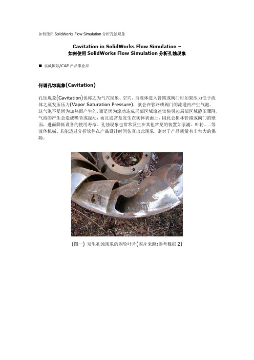
如何使用SolidWorks Flow Simulation分析孔蚀现象Cavitation in SolidWorks Flow Simulation –如何使用SolidWorks Flow Simulation分析孔蝕現象■實威國際/CAE產品事業部何謂孔蝕現象(Cavitation)孔蝕現象(Cavitation)也稱之為氣穴現象、空穴。
當液體進入管路或閥門時如果壓力低於流體之蒸發壓壓力(Vapor Saturation Pressure),就會在管路或閥門的流道內產生氣泡。
這氣泡不是因為加熱而產生的,而是因為流動造成局部區域流速較快引起局部區域靜壓驟降,氣泡的產生會造成噪音或振動,而且通常是發生在實體表面上,因此會損壞管路或閥門的壁面,進而降低設備的使用壽命。
孔蝕現象也常常發生在其他常見的裝置如泵浦、葉輪……等流體機械。
若能透過分析軟體在產品設計階段模擬出此現象,則對於產品品質有非常大的保障。
(圖一) 發生孔蝕現象的渦輪葉片(圖片來源:參考資料2)(圖二) 葉輪模型範例,吸入端至吐出端的壓力曲線,上方曲線是正常的,下方曲線低於蒸發壓力會發生孔蝕現象。
孔蝕現象在SolidWorks Flow Simulation1.SolidWorks Flow Simulation 2006以前版本。
SolidWorks Flow Simulation無法直接模擬出孔蝕現象。
不過,可以藉由分析結果中負壓的區域指出有孔蝕現象的區域。
2.SolidWorks Flow Simulation 2007之後版本。
SolidWorks Flow Simulation有一項新增功能,可以應用來評估是否發生孔蝕現象。
(圖三) 在SolidWorks Flow Simulation 2007版本之後,在流體流動特性(Flow Characteristic)中,就可以指定要不要啟動Cavitation選項。
使用建議• 若是分析水的流動,在分析的區域中有可能局部區域的靜態將低於液體在環境溫度下的蒸發壓力值或者是液體流過劇烈加熱區域使溫度上升至沸點而引起孔蝕現象,建議在Wizard 或General Settings的Fluid設定頁面中啟用Cavitation選項。
学习使用SolidWorksFlowSimulation进行流体分析
学习使用SolidWorksFlowSimulation进行流体分析Chapter 1: Introduction to SolidWorks Flow SimulationSolidWorks Flow Simulation is a powerful computational fluid dynamics (CFD) tool that allows engineers and designers to analyze the behavior of fluid flow and heat transfer within their designs. It is an integrated feature of SolidWorks, a popular 3D CAD software widely used in various industries.The purpose of this chapter is to provide a brief overview of SolidWorks Flow Simulation, its capabilities, and its benefits for engineers and designers.1.1 What is SolidWorks Flow Simulation?SolidWorks Flow Simulation is a CFD software package that enables engineers to simulate and analyze fluid flow, heat transfer, and related phenomena. It uses mathematical equations and numerical methods to solve complex fluid dynamics problems.1.2 Why Use SolidWorks Flow Simulation?There are several reasons why engineers and designers choose to use SolidWorks Flow Simulation:- Improved Design Efficiency: By simulating fluid flow and heat transfer early in the design process, engineers can identify and resolvepotential issues before physical prototypes are built. This saves time and reduces costs.- Accurate Results: SolidWorks Flow Simulation uses validated numerical algorithms to provide accurate results. It considers factors such as turbulence, flow rates, pressure drops, and thermal effects.- Visualization: SolidWorks Flow Simulation provides interactive 3D visualizations of fluid flow patterns, velocity vectors, temperature distributions, and other parameters. This helps engineers better understand the behavior of their designs.- Optimization: SolidWorks Flow Simulation offers optimization capabilities, allowing engineers to automatically find the best design parameters for their fluid systems. This can lead to improved performance and efficiency.1.3 Applications of SolidWorks Flow SimulationSolidWorks Flow Simulation has a wide range of applications in various industries, including:- Automotive: Analyzing airflow around vehicles, optimizing cooling systems, and improving aerodynamics.- Aerospace: Evaluating aircraft wing designs, studying fluid flow in jet engines, and optimizing heat transfer in spacecraft.- HVAC: Simulating air conditioning systems, optimizing ventilation design, and analyzing thermal comfort.- Electronics: Studying the cooling of electronic components, evaluating heat sink designs, and analyzing airflow in computer servers.Chapter 2: Getting Started with SolidWorks Flow SimulationChapter 2 provides a step-by-step guide on how to get started with SolidWorks Flow Simulation. It covers the basic workflow, setup, and analysis of a typical fluid flow problem.2.1 Creating a StudyThe first step in using SolidWorks Flow Simulation is to create a new study. This involves defining the fluid domain, selecting the appropriate fluid type, and specifying the boundary conditions.2.2 Meshing the GeometryAfter creating a study, the next step is to generate a mesh for the geometry. Meshing is the process of dividing the fluid domain into a network of small cells or elements. A finer mesh provides higher accuracy but requires more computational resources.2.3 Defining Boundary ConditionsBoundary conditions define the inputs and outputs of the fluid flow problem. This includes specifying the inlet velocity or pressure, outlet conditions, wall properties, and any additional constraints or assumptions.2.4 Solving the Flow ProblemOnce the geometry is meshed and the boundary conditions are set, SolidWorks Flow Simulation can solve the flow problem. This involves solving the Navier-Stokes equations, which describe the conservation of mass, momentum, and energy.2.5 Analyzing the ResultsAfter the flow problem is solved, engineers can analyze the results using various post-processing tools. This includes visualizing flow patterns, velocity profiles, pressure distributions, temperature gradients, and other relevant parameters.Chapter 3: Advanced Features and TechniquesChapter 3 explores some of the advanced features and techniques available in SolidWorks Flow Simulation. These features allow engineers to handle more complex fluid flow problems and obtain more detailed insights.3.1 Turbulence ModelingTurbulence modeling is crucial in accurately simulating turbulent flow, which is common in many real-world scenarios. SolidWorks Flow Simulation provides various turbulence models, such as the k-epsilon model and Reynolds stress model, to capture turbulence effects.3.2 Multiphase FlowMultiphase flow refers to the simultaneous flow of multiple fluid phases, such as gas-liquid, liquid-solid, or gas-liquid-solid. SolidWorksFlow Simulation offers tools to model and analyze multiphase flow phenomena, such as cavitation, droplet dynamics, and particle transport.3.3 Heat Transfer AnalysisSolidWorks Flow Simulation includes comprehensive heat transfer analysis capabilities. Engineers can analyze conduction, convection, and radiation heat transfer within their designs. This is particularly useful in evaluating thermal management solutions and optimizing heat dissipation.3.4 Fluid-Structure Interaction (FSI)Fluid-structure interaction occurs when the fluid flow affects the structural behavior of a design, and vice versa. SolidWorks Flow Simulation allows engineers to perform FSI analysis, enabling them to study the interaction between fluid forces and structural responses.Chapter 4: Case Studies and Real-Life ExamplesChapter 4 presents several case studies and real-life examples that demonstrate the practical applications of SolidWorks Flow Simulation. These examples cover a diverse range of industries and showcase the capabilities and benefits of the software.4.1 Automotive Cooling System OptimizationThis case study focuses on optimizing the cooling system of a car engine. By simulating the airflow around the radiator, fan, and othercomponents, engineers can identify design improvements that enhance cooling efficiency and reduce engine overheating.4.2 HVAC System Design OptimizationIn this example, SolidWorks Flow Simulation is used to optimize the design of an HVAC system in a commercial building. By analyzing air distribution, temperature gradients, and ventilation effectiveness, engineers can improve occupant comfort and energy efficiency.4.3 Electronics Cooling AnalysisThis case study demonstrates the thermal analysis of an electronic circuit board. SolidWorks Flow Simulation helps engineers evaluate heat sink designs, optimize airflow through the components, and ensure proper cooling of sensitive electronic devices.Chapter 5: ConclusionIn conclusion, SolidWorks Flow Simulation is a valuable tool for engineers and designers involved in fluid flow and heat transfer analysis. It provides a comprehensive set of features and capabilities that enable users to simulate, analyze, and optimize their designs.By integrating SolidWorks Flow Simulation into the design process, engineers can gain valuable insights, improve design efficiency, and make informed decisions that lead to better performing and more reliable products.Whether in automotive, aerospace, HVAC, or electronics industries, SolidWorks Flow Simulation offers a powerful solution for fluid analysis, contributing to safer, more efficient, and more innovative designs.。
SolidWorks Flow Simulation在臭氧均布器分析中的应用
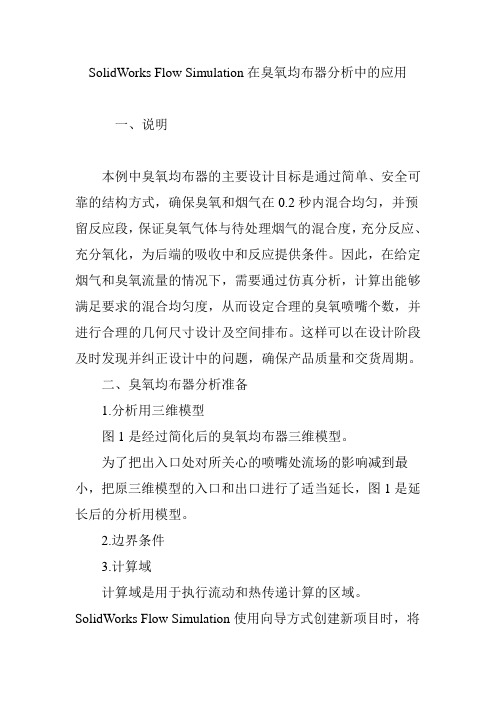
SolidWorks Flow Simulation在臭氧均布器分析中的应用一、说明本例中臭氧均布器的主要设计目标是通过简单、安全可靠的结构方式,确保臭氧和烟气在0.2秒内混合均匀,并预留反应段,保证臭氧气体与待处理烟气的混合度,充分反应、充分氧化,为后端的吸收中和反应提供条件。
因此,在给定烟气和臭氧流量的情况下,需要通过仿真分析,计算出能够满足要求的混合均匀度,从而设定合理的臭氧喷嘴个数,并进行合理的几何尺寸设计及空间排布。
这样可以在设计阶段及时发现并纠正设计中的问题,确保产品质量和交货周期。
二、臭氧均布器分析准备1.分析用三维模型图1是经过简化后的臭氧均布器三维模型。
为了把出入口处对所关心的喷嘴处流场的影响减到最小,把原三维模型的入口和出口进行了适当延长,图1是延长后的分析用模型。
2.边界条件3.计算域计算域是用于执行流动和热传递计算的区域。
SolidWorks Flow Simulation使用向导方式创建新项目时,将自动创建包含模型的计算域。
计算域是一个可用于3D分析和2D分析的长方体区域。
计算域边界平行于全局坐标系平面。
SolidWorks Flow Simulation也可以手动设置域以减少内部分析的计算域,或将计算域的边界平面移到外部,分析固体的更近或更远处。
本例中的计算域尺寸如表1所示。
4.初始条件所有稳态流动问题最初都被视为随时间变化的问题,并作为从指定初始流动状态到稳态流动的变化(在本例中是作为迭代),按时间步长进行解析。
因此,必须在整个计算域中指定初始流动条件,即独立流动参数的初始分布。
如果要以较短时间解析内部问题,只需指定比较接近假定解的初始条件。
本例中的初始条件设置如表2所示。
5.流体介质设置流体:烟气,臭氧。
6.分析目标设定SolidWorks Flow Simulation将所有稳态流动问题均视为随时间变化的问题。
求解器模块以内部确定的时间步长进行迭代以寻找稳态流场,因此需要确定已获得稳态流场的标准,以便停止计算。
如何使用SolidWorks_Flow_Simulation分析空蚀现象-气蚀分析
如何使用SolidWorks Flow Simulation分析孔蚀现象Cavitation in SolidWorks Flow Simulation –如何使用SolidWorks Flow Simulation分析孔蚀现象■实威国际/CAE产品事业部何谓孔蚀现象(Cavitation)孔蚀现象(Cavitation)也称之为气穴现象、空穴。
当液体进入管路或阀门时如果压力低于流体之蒸发压压力(Vapor Saturation Pressure),就会在管路或阀门的流道内产生气泡。
这气泡不是因为加热而产生的,而是因为流动造成局部区域流速较快引起局部区域静压骤降,气泡的产生会造成噪音或振动,而且通常是发生在实体表面上,因此会损坏管路或阀门的壁面,进而降低设备的使用寿命。
孔蚀现象也常常发生在其他常见的装置如泵浦、叶轮……等流体机械。
若能透过分析软件在产品设计时间仿真出此现象,则对于产品质量有非常大的保障。
(图一) 发生孔蚀现象的涡轮叶片(图片来源:参考数据2)(图二) 叶轮模型范例,吸入端至吐出端的压力曲线,上方曲线是正常的,下方曲线低于蒸发压力会发生孔蚀现象。
孔蚀现象在SolidWorks Flow Simulation1.SolidWorks Flow Simulation 2006以前版本。
SolidWorks Flow Simulation无法直接模拟出孔蚀现象。
不过,可以藉由分析结果中负压的区域指出有孔蚀现象的区域。
2.SolidWorks Flow Simulation 2007之后版本。
SolidWorks Flow Simulation有一项新增功能,可以应用来评估是否发生孔蚀现象。
(图三) 在SolidWorks Flow Simulation 2007版本之后,在流体流动特性(Flow Characteristic)中,就可以指定要不要启动Cavitation选项。
使用建议• 若是分析水的流动,在分析的区域中有可能局部区域的静态将低于液体在环境温度下的蒸发压力值或者是液体流过剧烈加热区域使温度上升至沸点而引起孔蚀现象,建议在Wizard 或General Settings的Fluid设定页面中启用Cavitation选项。
solidworks flow simulation工程实例详解
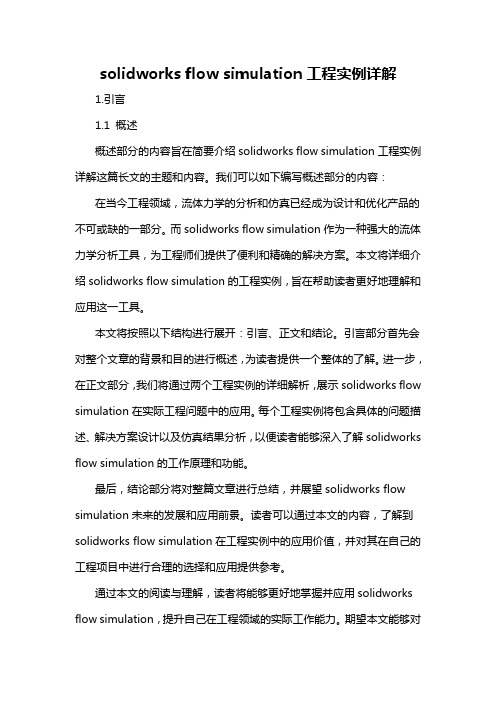
solidworks flow simulation工程实例详解1.引言1.1 概述概述部分的内容旨在简要介绍solidworks flow simulation工程实例详解这篇长文的主题和内容。
我们可以如下编写概述部分的内容:在当今工程领域,流体力学的分析和仿真已经成为设计和优化产品的不可或缺的一部分。
而solidworks flow simulation作为一种强大的流体力学分析工具,为工程师们提供了便利和精确的解决方案。
本文将详细介绍solidworks flow simulation的工程实例,旨在帮助读者更好地理解和应用这一工具。
本文将按照以下结构进行展开:引言、正文和结论。
引言部分首先会对整个文章的背景和目的进行概述,为读者提供一个整体的了解。
进一步,在正文部分,我们将通过两个工程实例的详细解析,展示solidworks flow simulation在实际工程问题中的应用。
每个工程实例将包含具体的问题描述、解决方案设计以及仿真结果分析,以便读者能够深入了解solidworks flow simulation的工作原理和功能。
最后,结论部分将对整篇文章进行总结,并展望solidworks flow simulation未来的发展和应用前景。
读者可以通过本文的内容,了解到solidworks flow simulation在工程实例中的应用价值,并对其在自己的工程项目中进行合理的选择和应用提供参考。
通过本文的阅读与理解,读者将能够更好地掌握并应用solidworks flow simulation,提升自己在工程领域的实际工作能力。
期望本文能够对有关solidworks flow simulation的工程专业人士提供一定的帮助和指导。
1.2 文章结构文章结构部分的内容可以包括以下内容:本文分为引言、正文和结论三部分。
引言部分包括概述、文章结构和目的三个小节。
在概述中,将介绍solidworks flow simulation工程实例的背景和重要性。
solidworks:hands on,使用Flow Simulation开始您的流体分析
汽车排气管
Click to edit Master text styles
Second level 在这个例子中我们将考察汽车尾气排放管一个截面的流动状态,在这 Third level 个截面上排出的尾气受到两块催化剂的阻碍,这两块催化剂属于多孔 Fourth level 介质,它的作用是将尾气中有害的一氧化碳气体转化为二氧化碳气体
Click to edit Master text styles
Second level
Third level
Fourth level Fifth level
使用Flow Simulation开始您的流体分析
广州宇喜资讯科技有限公司 张小林
日程
介绍 Click to edit Master text styles 实际动手做的例子 Second level 阀流量计算 Third level
阀流量计算
Click to edit Master text styles
Second level 创建一个新项目,并命名为flow rate
Third level
Fourth level Fifth level
阀流量计算
Click to edit Master text styles
Second level 选择单位系统,vel
定义边界条件
Click to edit Master text styles
Second levelopenings(流动入口) 选择 Flow Third level 和 Inlet Velocity(入口速度)
Fourth level Fifth level
定义边界条件
因此在前部催化剂的入口处大约13处流动应该比等向性的非均匀流更加值得关注比较单向性和等向性催化剂clickeditmastertextstylessecondlevelthirdlevelfourthlevelfifthlevel然而由于等向渗透性在等向性催化器内气流膨胀并且比单向性的催化剂在下一部分所占据的体积要大对于单向性的催化器由于它的单向渗透性阻碍了气流的膨胀所以在前部单向性催化器的后23的催化剂的流动比等向性的非均由于安装在管子中的前后两个多孔介质之间的距离相当小虽然在单向性的例子中可以看到一个确定方向流动在这么短的距离内气流没有时间变的更为均匀所以发生在前部催化体的出口处非均匀性流体进入后部催化体之后我们可以看到在后部催化体中非均匀性流体不会改变比较单向性和等向性催化剂clickeditmastertextstylessecondlevelthirdlevelfourthlevelfifthlevel首先对于扇叶的流体分析我们要定义一个内流分析内流分析我们则需要定义一个流体区域在solidworks中我们可以建立一个拉伸壳体厚度为5mm在后面的设定中我们要设定壳体内表面作为流体流动的边界条件风叶流体分析到结构分析方法clickeditmastertextstylessecondlevelthirdlevelfourthlevelfifthlevel风扇是最普遍的旋转流体分析对于旋转的流体分析在flowsimulation中需要定义一个旋转的区域用sw建立一个实体或者特征作为旋转域原则是完全包括扇叶最好大于扇叶风叶流体分析到结构分析方法clickeditmastertextstylessecondlevelthirdlevelfourthlevelfifthlevel开启一个算例风叶流体分析到结构分析方法clickeditmastertextstylessecondlevelthirdlevelfourthlevelfifthlevel输入算例名称风叶流体分析到结构分析方法clickeditmastertextstylessecondlevelthirdlevelfourthlevelfifthlevel选择计算单位选择系统默认风叶流体分析到结构分析方法clickeditmastertextstylessecondlevelthirdlevelfourthlevelfifthlevel理特征旋转分析风叶
solidworks的流体仿真案例讲解

solidworks的流体仿真案例讲解SolidWorks是一款广泛应用于机械工程领域的三维建模软件,它不仅可以进行零件设计和装配设计,还具备流体仿真功能。
通过SolidWorks的流体仿真模块,用户可以对流体流动、传热和压力等进行分析和预测,从而优化设计方案,提高产品性能。
下面将以SolidWorks的流体仿真案例为例,介绍几个常见的应用场景。
1. 空气流动分析:在汽车、飞机等交通工具的设计中,空气动力学性能的优化非常重要。
通过SolidWorks的流体仿真模块,可以对车身外形、雨刮器、车窗等部件的设计进行模拟和优化,以提高车辆行驶的稳定性和降低空气阻力。
2. 水流动分析:在船舶和水利工程设计中,水流动的分析和优化是必不可少的。
通过SolidWorks的流体仿真模块,可以对船体外形、舵面、螺旋桨等进行模拟和优化,以提高船舶的操纵性和减少能耗。
3. 管道流体分析:在石油、化工、能源等领域,管道系统的设计和优化对于工艺流程的高效运行至关重要。
通过SolidWorks的流体仿真模块,可以对管道系统中的流速、压力和温度等进行模拟和优化,以提高管道系统的流量、降低能耗和减少泄漏风险。
4. 空调系统分析:在建筑设计中,空调系统的设计和优化对于室内舒适性和能源节约至关重要。
通过SolidWorks的流体仿真模块,可以对空调系统的送风口、回风口和管道进行模拟和优化,以提高空调系统的均匀性和节能性能。
5. 风扇设计分析:在电子设备和机械设备中,风扇的设计和优化对于散热和噪声控制非常重要。
通过SolidWorks的流体仿真模块,可以对风扇的叶片形状、叶片角度和转速等进行模拟和优化,以提高风扇的散热效率和降低噪声。
6. 液压系统分析:在工程机械和航空航天设备中,液压系统的设计和优化对于工作稳定性和能源效率至关重要。
通过SolidWorks的流体仿真模块,可以对液压系统中的液压缸、液压泵和液压阀进行模拟和优化,以提高液压系统的工作效率和降低能耗。
solidworks:hands on,使用Flow Simulation开始您的流体分析
项目向导
Click to edit Master text styles
Second level 点击Flow Simulation—Solve—Run,开始运行仿真 Third level 运行完成后,查看仿真结果,右击Results文件夹下的Goals,选择 Fourth level insert,选择SG Volume Flow Rate 1并单击OK,计算结果以Excel表格 Fifth level 的形式显示
对于这个项目所有的这些设置都是合适的,我们所要做的仅仅是将空 气作为项目的流体。为了避免经过每一个向导界面,我们将使用 Navigator (导航)面板,它可以使我们快速的访问向导页
项目向导
Click to edit Master text styles
Second level
Third level
汽车排气管
Click to edit Master text styles
Second level 在这个例子中我们将考察汽车尾气排放管一个截面的流动状态,在这 Third level 个截面上排出的尾气受到两块催化剂的阻碍,这两块催化剂属于多孔 Fourth level 介质,它的作用是将尾气中有害的一氧化碳气体转化为二氧化碳气体
单位系统 – SI 流体介质 - air 分析类型 – Internal(内部流动),no additional physical capabilities are considered(没有任何附加物理特征被选择) 壁面状况 – adiabatic wall(绝热壁面) 初始条件 – pressure 1 atm(1个大气压强),temperature(温度) 293.2 K 结果和几何求解 – level 3