新能基推出最新LED电源测试系统
液晶杜邦17011电源电源测试系统说明书

EthernetMODEL 17011KEY FEATURESHigh precision output and measurement up to 0.015% of full scaleFast current response up to <100 µS High sampling rate up to 10 mS Flexible sampling recording ( t, V , I, Q, E)Channel parallel output function with maximum 1200A outputHigh efficiency charge and discharge with low heatingEnergy recycling during discharge (AC/DC bi-directional regenerative series) Waveform simulation function (current/power mode) Built-in DCIR test functionBuilt-in EDLC capacitance and DCR test functionOperating modes: CC / CP / CV / CR / CC-CV / CP-CV / Rest / SD test Multi-level safety protection mechanism Integrable data logger and chamberAPPLICATIONSElectric vehicle Electric scooter/bike Energy storage system Power toolsQuality inspection agency The Chroma 17011 Battery Cell Charge and D ischarge Test System is a high precision system designed specifically for testing lithium-ion battery (LIB) cells, electrical double layer capacitors (ED LC), and lithium-ion capacitors (LIC). It is suitable for product development, quality control, and is helpful program editing and test results analysis much easier.The Chroma 17011 test system has flexible software editing functions embedded that can create basic charging/discharging or complex cycle tests for each channel to run BATTERY CELL CHARGE & DISCHARGETEST SYSTEM MODEL 17011P r o vided b vided by y : com (800)40404-A -ATE TEC CAd Advanced vanced T Test estE quipment Rentals®High precision – improving product qualityVoltage / current measurement accuracy: 0.015 of F.S. / 0.02 of F.S.Wide range of voltage output: Equipped with a 0V to 6V output range, and specific models allow to switch between three built-in voltage output modes. Voltage measurements distinguished up to 0.1mV.Multiple range measurement design: Providing various current or voltage ranges (depending on the model) to greatly improve measurement accuracy and resolution. The current range switches automatically and at the constant voltage mode there is no current output interruption.Fast current response – suitable for a variety of high-speed transient test applicationsCurrent response time (10% to 90%) < 100 µS *1Support dynamic waveform to simulate the rapid changing current and power states*1: The current response time <100 µS applies to model 17216M-10-6, the impedance of other UUTswill slightly differ.Rise Time<100 µS (17216M-10-6)Rise Time<250 µS (17208M-6-30)Model 17216M-10-6Model 17216M-6-12Model 17208M-6-30Model 17208M-6-60Multi-Voltage Range (17216M-10-6)Multi-Current RangeLoading waveform currentDynamic waveform simulation Dynamic waveform simulationCurrent and power dynamic charge/discharge waveform, simulate the actual battery usage of car driving or other real life applicationsImport the current and power waveforms from Excel fileSave 1,440,000 points in each channel for long hour dynamic testingMinimalize time interval for data output: 10 mS*1: 17216M-10-6 has three built-in voltage output modes that can be switched through the software settings.*2: 17208M-6-60 has to be paired with an external power supply and placed into a rack; other models contain an integrated power module and can beused either stand-alone or in a rack.Rise time < 5 mSEnergy recycling – optimal utilization of electricityDirect recycling: Automatically transfer the discharging energy to the battery cells to be charged with recycling efficiency >80% Grid recycling: Recycle the excessiveenergy to the grid with recyclingefficiency >60%Low carbon emissions for green energy,preventing waste heat from generatingduring dischargeSaving electricity costs with highefficiency power charge and dischargeSaving air conditioning costs on coolingequipmentCurrent harmonic distortion <5%for feedback to grid currentPower factor >0.98 at rated powerHigh precision – improving product qualityVoltage accuracy: (0.02% of Reading + 0.02% of F.S.)Current accuracy: 0.05% of F.S.Fast current response – waveform modeCurrent response speed (10% to 90%) < 5 mS applicablefor all kinds of testsSupport dynamic waveform to simulate the current and power stateof actual car driving with NEDC, FUDS and DST test standardsAC/DCChroma 17212M-6-100Chroma A691104Direct RegenerationAC/DC* A fitting AC/DC bi-directional converter is chosen according to the power input and placed into a rack.Flexible paralleling channels for outputT h e t e s t s y s t e m s a l l o w f l e x i b l e s e t t i n g f o for various UUTs.which supports full range of productsSuitable for high ratio charge and discharge test or diversified battery test applicationsData protection and recoveryPower loss data restoring mechanism: After a power loss, the PC will automatically recover the data status of the testingdata that already was written into the database. The user can choose to resume or restart testing.High frequency sampling measurement technology – improving measurement accuracyV / I sampling rate: 50 KHz (∆t 20 µS)Generally, battery testers use software to read current values for calculating power; however, limited data sampling rates could result in large errors when calculating the dynamic current capacity. By increasing the sampling rate and using a double integration method, Chroma 17011 is able to provide a capacity calculation with much higher accuracy. When the current changes, the data is not lost and the transmission speed is not affected.* Note: The current response time <100 µS applies to model 17216M-10-6, the impedance of other UUTs will slightly differ.General charger/discharger sampling rateChroma charge & discharge tester sampling rateHPPC TestHPPC test applicationHPPC is a test procedure developed by the USABC (U.S. Advanced Battery Consortium) for the battery power performance of hybrid and electric vehicles. Within the batteries operation voltage range, the procedure mainly establishes the function of the relationship between the depth of discharge and power and, secondarily, establishes the depth of discharge, conductive resistance and polarization resistance function via the voltage and current response curve from discharging, standing to charging. The measured resistance can be used to assess the battery's power recession during later life tests and its equivalent circuit model development. Chroma 17011 has a flexible editing program that allows HPPC testing.DCIR test (2)DCIR test (1)Lumped parameter model circuit diagram Battery capacity test applicationT h e c a p a c i t y c a n b e o b t a i n e d a s t h e i n t e g r a l o f t h e c u r re n t integrating the current versus time from the start of charging/discharging until the cut-off condition is reached. The comparison results are useful to analyze performance differences between products, and the common test items include current ratio and temperature characteristics tests. Higher accuracy of current, voltage measurement and faster sampling enable to distinguish more accurately the differences in battery cell capacity.Battery cycle life test applicationCycle life is one of the most important test items for batteries. In accordance with the experimental purpose, it tests the same battery through repeated charge and discharge conditions until the capacity falls to 80%, and calculates the cycle numbers. The cycle life test can be used to evaluate the battery performance or define the applicable conditions of use.Battery DCIR test applicationThe internal resistance value is related to the charge/discharge ratio of a battery. The larger the internal resistance value, the lower the efficiency when temperature rises. According to the lithium-ion battery equivalent circuit model, the ACIR measurement of traditional 1KHz LCR meters can only evaluate the conductive resistance (Ro) of the battery that affects the instantaneous power output, but is unable to evaluate the polarization resistance (Rp) produced during electrochemical reaction. The D CIR evaluation includes the ACIR that is closer to the actual polarization effect of battery under continuous power applications.The Chroma 17011 includes two types of D CIR test modes: DCIR test (1) calculates the DCIR value using the voltage difference caused by the change of one-step current, DCIR test (2) calculates the DCIR value using the voltage difference caused by the change of two-step current. Users can select the desired test mode and automatically, without any manual calculation, get the results that comply with IEC 61960 standards.CapacitydQ/dV vs voltageCoulombic efficiency test Incremental capacity analysis applicationThe high precision voltage measurement and V sampling function can draw dQ/dV versus voltage curve diagrams to analyze battery cell characteristics and capacity degradation.Coulombic efficiency test applicationCoulombic efficiency (CE) is calculated by the charge/discharge capacity ratio when the battery is fully charged and then fully discharged. Good batteries have higher coulombic efficiency, and need high precision and stable equipment to distinguish differences. An accurate coulombic efficiency test can estimate the batterylifespan with only a few cycles.EDLC capacitance (C) test applicationIn accordance with the Straight Line Approximation Method of the IEC 62391 testing standard, before measuring the capacitance (C) value, the ED LC first needs to be fully charged through a CC-CV charging mode. The capacity test is to discharge CC via the above discharge current. Then, the electric potential difference ( V) of two reference points on the discharge curve are taken against the time difference ( t) and the discharge current (I) to calculate the capacitance value of the EDLC.EDLC combined DCR and C test applicationChroma 17011 also has a direct current resistance (D CR) and capacitance (C) combined test application. Under the same CC-CV charged and CC discharged conditions, the user can use the electric potential in the chosen reference points to simultaneously calculate the DCR and C values of the EDLC to save testing time.The equivalent circuit model development of the classical EDLC includes an equivalent series resistance (ESR), a capacitance (C), and an equivalent parallel resistance (EPR). The ESR is used to evaluate the internal loss and heat of the EDLC during charging/discharging; the EPR to evaluate the leakage effect in the EDLC's long-term storage; the C to evaluate the EDLC cycle life.These parameters are not easily directly measured in a laboratory; researchers need data analysis and complex calculations to determine these important indicators. Chroma 17011 is equipped with the IEC 62391 testing standards and the user can use charge/discharge tests to obtain the ED LC parameters values, in order to evaluate the EDLC characteristics and cycle life.ED LC direct current resistance (D CR) and equivalent series resistance (ESR) test applicationChroma 17011 offers ED LC direct current resistance testing function compliant with test standard IEC 62391. Before testing, the ED LC has to be CV charged. The capacity test is to discharge CC via the above discharge current. When the discharge is completed, get the linear section on the discharge curve and extend it to discharge time and then get the voltage difference of rated voltage and discharge current to calculate the DCR value.EDLC equivalent circuit model developmentVoltage Characteristic Between EDLC TerminalsVoltage Characteristic Between EDLC TerminalsVoltage Characteristic Between EDLC TerminalsCharge/discharge performance and cycle life test applicationThe built-in direct current resistance (D CR) and capacitance (C) test modes can be combined with cycle function and variable set testing conditions to test the EDLC load endurance and reliability. After testing, the user can directly export DCR vs Cycle No. and Capacity vs Cycle No. reports to analyze the EDLC failure and deterioration mechanisms.Self-discharge test modeCoulombic efficiency testAutomatically change current range in CC-CV modeCharge-Discharge Rate Test Charge-Discharge Cycle TestingCoulombic efficiency test applicationChroma 17011 is equipped with low noise, automatically switching current range, and cut-off report as to quickly output accurate c u r re n t c h a rg e /d i s c h a rg e. T h e c o u l o m b i c e ff i c i e n c y (C E ) i s calculated by the charge/discharge capacity ratio, which indicates the ED LC internal capacity conversion as available capacity. A highly accurate CE is an important marker to distinguish differences between products.Leakage current test applicationED LC leakage current measurements generally need to CC-CV charging until a specific time and then it measures this tiny charging current, which is seen as leakage current. The Chroma 17011 CC-CV mode can automatically change current range without output interruption. Under stable voltage, the current range can be as small as 200µA.Current (A)Self-discharge test applicationChroma 17011 also has a built-in self-discharge test mode, when the ED LC is fully charged it can test the charge/discharge for a set time period. When this mode starts, the system will cut off the measuring circuit to provide the ideal open circuit and solely measure the starting potential (V1) and cut-off potential (V2). The software can automatically calculate the electric potential difference ( V).CE=Q Discharge / Q ChargeThe Chroma 17011 test systems are controlled by computer software with diverse functions for testing energy storage products. The safe, stable and friendly operation interface allows users to perform setting and testing rapidly.Support English, Traditional Chinese, and Simplified Chinese languages interfaces Real time multi-channel DUT status monitoringSecurity management: set user authority for safe managementFailure record tracking: independently record abnormalities for each channel, the charge and discharge protection will abort the testwhen an abnormal condition is detectedRecipe editing500 steps per recipeDouble loop (Cycle & Loop) with 999,999 repeat counts per loop Sub-recipe function: Call existing recipesTest steps : CC / CV / CP / CC-CV / CP-CV / CR / Rest / Waveform / DCIR / C / DCR, etc. Cut-off conditions : Time / Current / Capacity / Power / Variable, etc. Logical operations : Next / End / Jump / If-Then Recipe executingOperating modes: Start / Stop / Pause / Resume / Jump / Reserve Pause / Modify during test Display interfaces: Graphic display / Table display Instant monitoring windowStatistics reportAble to define report formats and export them as PDF, CSV, and XLS filesGraphical report analysis functions allow custom reports such as cycle life reports, Q-V reports, V / I / T time reports, etc.Real time monitoring Charge/Discharge test program editor Test diagram Test reportBattery Pro main panelWaveform current editorIntegrate with an environmental chamber through software to synchronize the settings conditions for charge/discharge testingIntegrate with a multifunctional data logger through software to read and set multiple temperature records during thecharge/discharge process. Change these conditions to protection or cut-off conditions17011 SystemData LoggerLinear circuit modelsThe tester can be used stand-alone to take up little space, which fits a handful of tests performed on the desktop. When the tester is configured with more test channels, it can be integrated into a standard 19-inch rack for use. The system can be configured as demanded by the user as the channel numbers are expandable, and up to 64 channels can be controlled by one PC at the same time.60A 36U rackModel 17208M-6-306A/12A/30A 36U rackModel 17216M-10-625U rackRegenerative modelsA charge/discharge tester and an AC/D C bi-direction converter can be integrated into a standard 19-inch rack for use. The system can be configured as demanded by the user as the channel numbers are expandable, and up to 48 channels can be controlled by one PC at the same time.Chroma 17011 system power consumption * Available space for data logger60A / 41U system100A / 41U systemORDERING INFORMATION17011 : Battery Cell Charge & Discharge Test System17216M-10-6 : Programmable Charge/Discharge Tester, 10V / 6A, 16CH 17216M-6-12 : Programmable Charge/Discharge Tester, 6V / 12A, 16CH 17208M-6-30 : Programmable Charge/Discharge Tester, 6V / 30A, 8CH 17208M-6-60 : Programmable Charge/Discharge Tester, 6V / 60A, 8CH 17212R-5-60 : Programmable Charge/Discharge Tester, 5V / 60A, 12CH 17212R-5-100 : Programmable Charge/Discharge Tester, 5V / 100A, 12CH 17212M-6-100 : Programmable Charge/Discharge Tester, 6V / 100A, 12CH A691103 : DC/AC Bi-direction Converter, AC 220V to DC 45V A691104 : DC/AC Bi-direction Converter, AC 380V to DC 45V* All specifications are subject to change without notice.* Continued on next pageNote*1: The maximum discharge current will derate at low voltage 17011-E-201908-PDFJAPANCHROMA JAPAN CORP .888 Nippa-cho, Kouhoku-ku,Yokohama-shi,Kanagawa,223-0057 Japan T +81-45-542-1118F +81-45-542-1080www.chroma.co.jp**************.jp U.S.A.CHROMA ATE INC.(U.S.A.)7 Chrysler, Irvine,CA 92618T +1-949-421-0355F + *****************CHROMA SYSTEMS SOLUTIONS, INC.19772 Pauling, Foothill Ranch, CA 92610 T +1-949-600-6400F + *******************EUROPECHROMA ATE EUROPE B.V .Morsestraat 32, 6716 AH Ede,The Netherlands T +31-318-648282F + ******************CHROMA GERMANY GMBH Südtiroler Str. 9, 86165,Augsburg, Germany T +49-821-790967-0F + ******************CHINA CHROMA ELECTRONICS (SHENZHEN) CO., LTD.8F , No.4, Nanyou Tian An Industrial Estate,Shenzhen, China T +86-755-2664-4598F +86-755-2641-9620 ******************SOUTHEAST ASIA QUANTEL PTE LTD.(A company of Chroma Group)46 Lorong 17 Geylang # 05-02 Enterprise Industrial Building,Singapore 388568T +65-6745-3200F + ************************HEADQUARTERS CHROMA ATE INC.66 Huaya 1st Road,Guishan, Taoyuan 33383, TaiwanT +886-3-327-9999F + ******************KOREA CHROMA ATE KOREA BRANCH 3F Richtogether Center, 14,Pangyoyeok-ro 192,Bundang-gu,Seongnam-si,Gyeonggi-do13524, Korea T +82-31-781-1025F +82-31-8017-6614www.chromaate.co.kr ******************17011。
LED测试系统使用说明

陈青松 2011-08-17
系统主界面
工具栏
点击主界面工具栏系统登录按钮,输入用户 名和密码,管理员账号密码均为admin,以管 理员身份登录后会多出系统校正面板,可以 进行光谱仪和电路板基本参数的校正 复位后将清除所有测试数据,计数清零,恢复 到系统初始状态
在主菜单文件子菜单里,可以将当前设置参数 另存为其它文件名,然后通过载入设置重新 载入到系统中
led光电综合测试系统介绍陈青松20110817工具栏点击主界面工具栏系统登录按钮输入用户名和密码管理员账号密码均为admin以管理员身份登录后会多出系统校正面板可以进行光谱仪和电路板基本参数的校正复位后将清除所有测试数据计数清零恢复到系统初始状态在主菜单文件子菜单里可以将当前设置参数另存为其它文件名然后通过载入设置重新载入到系统中工具栏保存当前所有设置窗口标题栏会显示当前配置文件名自动运行按钮按下后系统进入自动运行状态此时系统接收到plc的sot信号后开始测试测试完毕后将bin号和eot信号发送到plc
系统规范 电性测试项目及时间: 电性测试项目:极性POL、反向漏电IR、反 向电压VR、开启电压VFin、正向电流IF、正 向电压VF、亮度IV 典型测试时间: 30ms (单晶,POL、IR、VF、IV) 90ms (三晶,POL、IR、VF、IV)
系统规范 光学测试项目及时间: 光学测试项目:色坐标CIE_xy、主波长λd 、 色纯度PUR、峰值波长λp、色温CCT、光通量 LM、显色指数CRI、半高宽FWHM、色容差 SDCM 最小测试时间 * 10ms
± 0.002 ± 0.35 nm ± 0.5 nm
工具栏
连续测试按钮按下后,系统将进入单灯连续测
试状态,连续测试的相关设置将在后面的单灯测 试统计界面进行介绍。和单步测试一样,系统不 接收SOT信号,也不发送BIN号及EOT信号。
LED驱动电源测试方案
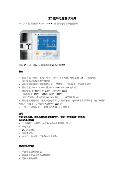
LED驱动电源测试方案一、多功能可编程的AC/DC SOURCE,保证稳定可靠的能量供给。
日本NF公司,1KVA 可编程多功能AC/DC SOURCE特点∙测量功能(电压,电流,功率,频率,功率因数,峰值系数(CF),谐波电流)∙可对输出进行编程的序列功能∙可用控制软件进行测量值的记录(LOGGING)、序列编辑、任意波形制作∙输出容量750VA(AC100V输入时)/1kVA(AC200V输入时)∙交流输出 0~135V*/0~270V*、频率DC~550Hz直流输出 -190V~+190V*/-380V~+380V*可以在直流上叠加交流(AC+DC)输出*AC200V输入时∙输出电流限制功能、最大峰值电流可达4倍的输出、电压/频率上下限设定功能、外部信号输入、USB接口、电源输入AC90V~250V等∙小型(台式机尺寸)、轻量(约9.5kg)、易携带应用作为交流电源,直流电源和测试测量用电,满足不同领域的不同需求适用机器和领域∙ DC电源组,特别是LED等中小功率电源研发、测试。
∙家电设备∙ OA, 通信设备∙汽车电装品∙电容器, 继电器, 开关等电子零部件测试对象和用途∙电源电压的变动测试∙电源电压失真系数的耐量测试∙消耗功率的评价∙负载功率因素的测量∙作为测试·测量信号的功率放大器∙作为生产·检测线电源∙作为研究室,实验室的稳压电源二、精准、多功能的功率分析仪美国思创XITRON 2801/2802多功能功率分析仪,完全附合最新能源之星标准,瞬间测试300多IEC要求测试项目,性价比超群,为GE、PHILIPS、OSRAM指定品牌。
2801 / 2802 Advanced Single- and Two-Channel Power AnalyzersWith an extended measurement range from micro-amps to hundreds of amps andmilli-volts to kilovolts, the XiTRON 2801 and 2802 are ideal analyzers for standby power or Energy Star testing. Numeric results and waveforms can be displayed, read via the communication ports (RS-232, GPIB, USB, and Ethernet), or sent directly atfull resolution to a USB printer.∙Highest Performance-to-Cost ratio in the industry∙Base accuracy <0.08%. Current and voltage accuracies specified to less than 1mArms and 1Vrms respectively (<0.2%)∙2000Vpk and 150Apk measurable internally (external CT capable)∙Integrated line switch and inrush waveforms∙Graphics display shows numerical results, waveforms, bar graphs, startup & history charts with zoom & scroll features∙Wiring loss and voltage burden compensation∙DC charge and discharge measurements∙Frequency Range: DC and 20mHz – 200kHz∙Communications ports include USB, GPIB, and RS-232 standard, plus optional Ethernet*∙USB Flash drive support for data logging*∙Provides PASS/FAIL tests to user limits*XITRON 2801/2802 应用优势领域:思创第一代功率分析仪的面世就是以PHILIPS、GE、SIEMENS要求研发,主要针对其灯具产品的小功耗测试,到目前为止XITRON仍为以上国际知名公司的指定功率测试仪器,在行业内有极好的口碑。
LED光色电综合测量系统项目立项申请说明word可编辑

LED光色电综合测量系统项目立项申请说明当前我国制造业还处在产业链和价值链的中低端,工业经济持续向好基础还要进一步巩固和提高。
经济运行中还面临着一些困难和挑战。
坚持以供给侧结构性改革为主线,主动对标对表高质量发展要求,沉着应对外部各种风险挑战,不断提高工业生产的供给质量,持续扩大有效需求,努力保持工业经济稳中向好的势头。
一、项目名称及承办单位(一)项目名称LED光色电综合测量系统项目(二)项目承办单位xxx科技公司二、项目建设地址及负责人(一)项目选址某某高新技术产业开发区(二)项目负责人尹xx三、项目承办单位基本情况在本着“质量第一,信誉至上”的经营宗旨,高瞻远瞩的经营方针,不断创新,全面提升产品品牌特色及服务内涵,强化公司形象,立志成为全国知名的产品供应商。
公司紧跟市场动态,不断提升企业市场竞争力。
基于大数据分析考虑用户多样化需求,以此为基础制定相应服务策略的市场及经营体系,并综合考虑用户端消费特征,打造综合服务体系。
公司近年来的快速发展主要得益于企业对于产品和服务的前瞻性研发布局。
公司所属行业对产品和服务的定制化要求较高,公司技术与管理团队专业和稳定,对行业和客户需求理解到位,以及公司不断加强研发投入,保证了产品研发目标的实施。
未来,公司将坚持研发投入,稳定研发团队,加大研发人才引进与培养,保证公司在行业内的技术领先水平。
四、项目建设地基本情况园区规划面积50平方公里,启动区面积为10平方公里,处于多条高速公路交织地带,是贵州省东西、南北交通节点城市,也是陆路出海通道必经之地。
铁路与公路交通极其便利。
目前园区内已成为全省重要的经济增长极,是发挥自身资源优势与产业集群效应的重要平台。
五、项目提出理由项目承办单位现有资产运营优良,财务管理制度健全且完善,企业的资金雄厚,凭借优异的产品质量、严谨科学的管理和灵活通畅的销售网络,连年实现盈利,能够为项目建设提供充足的计划自筹资金。
六、产品方案及建设规模(一)产品方案项目主要产品为LED光色电综合测量系统,根据市场情况,预计年产值12616.00万元。
LED光电特性的测试方案
LED光电特性的测试方案测试LED光电特性的方案可以分为以下几个步骤:1.设备准备:-LED芯片/光源-光学环境控制设备(光源、反射板、光强计、光谱仪等)-电子测试设备(电压源、电流表、电阻表等)-计算机及数据采集设备2.搭建测试装置:-将LED芯片/光源安装在适当的平台上,并连接好电源线和测试仪表-设置光学环境控制设备,如调节光源亮度、选择合适的反射板等3.测量LED的光谱特性:-使用光谱仪测量LED的光谱,获取LED在不同波长下的辐射光强数据-分析并记录光谱数据,以了解LED的光谱分布、光色性质等4.测量LED的光电流特性:-将LED连接到电源,并设置适当的电压和电流条件-使用光强计测量LED辐射的光强,并记录相应的电压和电流数据-分析并记录光电流特性数据,如I-V曲线、光电流-光强关系等5.测量LED的光效特性:-测量LED的光功率和电功率,并计算LED的光效(即光电转换效率)-分析并记录光效特性数据,以评估LED的性能和功耗情况6.其他测试:-进一步测试LED的发光角度、色温、色纯度等光学性能指标-测试LED的发光寿命、温度特性等可靠性指标7.数据分析和报告编写:-对上述测试数据进行分析和整理,比较不同LED的性能特点-根据测试结果编写测试报告,包括实验设计、测试过程、测试数据和结论等8.优化和改进:-根据测试结果,针对性地优化LED的设计和制造过程,改进其性能特点-根据测试经验,优化测试方案,提高测试效率和准确度在实际测试中,还需要注意以下几个方面:-定义明确的测试目标和指标,根据实际需求选择合适的测试参数和测试方法-保证测试环境的稳定性和一致性,避免外界干扰对测试结果的影响-根据测试需求选择合适的测试仪器和设备,确保其精度、灵敏度和可靠性-在测试过程中及时记录和保存测试数据,以备后续分析和验证-对测试结果进行验证和重复测试,以提高测试结果的可靠性和准确性-在测试完成后,对测试装置进行清理和维护,准备下一次测试通过以上测试方案,可以全面了解LED的光电特性,评估其性能优劣,为后续LED产品的设计和制造提供重要参考和指导。
LED驱动电源的检测经验

LED 驱动电源的检测经验1、检测方法:由于LED 驱动电源是恒流控制,理论上我们将其看做是恒流源,从电学理论上知道,恒流源不能开路,再加上电子负载机的特点(前端通电后才能够加载电流),因此,不能使用常见的电子负载机测试。
(电子负载机上得到的现象是:数字跳变,会误判驱动电源故障)制作负载:a 、购买3个200欧姆100W 的线绕可调电阻,前1个电阻的可调端(接线后面用鳄鱼夹,以方便调节电阻个数)接在后1电阻的前端,如此3个电阻串联,然后再串联1个大功率1W 的LED 并联组(6个1W 的LED 并联),前面的电阻的前端与LED 的后端的2个分别引线,按照LED 的+、—作为负载的-、+极;(6个并联的1W LED 可以通过的电流将达到2A ,至少不会因为电源的故障而引起烧毁LED 灯板 )b 、将此组合作为LED 电源的负载接在LED 驱动电源的对应输出引脚,其间串联1个电流表;c 、用万用表的二极管档分别测试交流输入端、整流后的+、-端是否有短路,没有,则可以通电;d 、在此负载2端接上万用表的对应+、-表笔 ,万用表置于大于LED 灯板串联数的总电压(LED 串联数*LED 的电压降,通常是3.3V )的档位, 调整电阻个数及接入电路的电阻的可调端,使得到的电压等于成品LED 板串联的总电压;e 、从电流表上读出的电流数,就是你的驱动电源在此LED 串联数条件下的输出电流;f 、 如果担心电流表的内阻影响驱动电源的输出电流,那么可以选几个精密金属膜电阻并联,得到1欧姆以下的电阻(用电桥测量得到其准确的阻值),串联在线路中,通电后用万用表测量此电阻两端的电压,通过计算得到整个电路的输出电流。
2、仪器从LED 驱动电源设计、检测的角度,至少应该具有以下三种设备:a 、可调交流电源,品牌如Chroma ,如果因为成本问题,可以选购大陆生产的;或者是自藕变压器,但220V 交流输入端需要接个1A 的保险丝(焊接型或电工保险(盒)丝或交流过流保护开关),避免驱动电源出现短路故障而引起市电跳闸;b 、示波器,依据自身的条件选购,最低要求是2G 、500M 2通道;c 、数字万用表,建议是4位半以上,按照上面的使用,最少3个。
LED驱动电源测试方法 图文精

万用表、电子负载 过流保护 输入电压为额定值,在负载电流为
额定负载,调节电子负载电流使之
升高直到进入驱动器的过流保 护状态。记录进入保护的临界值为
过流保护点
万用表、电子负载
交流振动声过载10%的额定输入电压、额定的
电源频率和额定负载下、1H之内无
交流声电
气
性
要
求环境噪音<40dB测听距离30cm
示波器、10UF电解
电容、0.1UF瓷片电容、电子负载 参考标准
亮度控制将电子负载接上电量测试仪,调光开关接到交流电源输入端,用调光 开关来控制驱动电源输入功率,测量驱动电源输出电压、电流数值
电量测试仪、调光开关、万用表针对调光电源负载开路保护输入电压为额 定值,在负载电压为
额定负载电压时,断开开关,测量输出电压值即为输出负载开路
机;
(2.依规格设定好温控室的温度
和湿度,然后启动温控室;
(3.定时记录待测品输入功率和
输出电压,以及待测品是否有异常;
(4.做完测试后回温到室温,再将
待测品从温控室中移出,在常温环
境下至少恢复4小时.
然后确认其外观和电气性能有无异
常
高低温交变湿热试 验箱、电子负载、 交流电源、电量测 试仪
雷击浪涌测试
和湿度,然后启动温控室
(3.定时记录待测品输入功率和
输出电压,以及待测品是否有异常;
(4.做完测试后回温到室温,再将
待测品从温控室中移出,在常温环
境下至少恢复4小时.
然后确认其外观和电气性能有无异
常
高低温交变湿热试验箱、电子负载、交流电源、电量测试仪
低温测试将待测品置于温控室内,依规格设
定好输入输出测试条件,然后开
IT8800 使用手册说明书

用户使用手册
直流可编程电子负载
IT8800 系列
型号IT8811/IT8812 IT8812B/IT8812C
© 版权归属于艾德克斯电子有限公司 Ver1.13 /MAR, 2012/ IT8800-701
1
用户使用手册
目录
IT8800 使用手册
第一章 验货与安装 ............................................................... 6
第二章 快速入门............................................................................................................................................ 9
2.1 开机自检 .............................................................................................................................................. 9 2.1.1 介绍 .............................................................................................................................................. 9 2.1.2 自检步骤....................................................................................................................................... 9 2.1.3 如果负载不能启动 ...................................................................................................................... 10
- 1、下载文档前请自行甄别文档内容的完整性,平台不提供额外的编辑、内容补充、找答案等附加服务。
- 2、"仅部分预览"的文档,不可在线预览部分如存在完整性等问题,可反馈申请退款(可完整预览的文档不适用该条件!)。
- 3、如文档侵犯您的权益,请联系客服反馈,我们会尽快为您处理(人工客服工作时间:9:00-18:30)。
新能基推出最新LED电源测试系统
※真正模拟LED负载模式,自动化测试,为客户节约测试时间,有效降低测试成本! ※真正模拟LED V-I特性曲线之非线性现象.
※全球领先的LED电源测试技术.
带给企业的优势:
1.能有效地解决电源产品的功能测试,有效的排除了手工测试产生错误的可能性!
2.能将测试数据完整地形成电子表格,永久存档以便追溯。
3.有效地降低测试成本,为客户赢取更多订单!
测试项目:
启动测试(Start-up)
欠压测试(UVLO)
待机测试(Idle) 恒压区测试(Standard CV)
恒流区测试(Standard CC) 短路测试(Short Circuit)
过压测试(Over Voltage) 过流测试(Over Current)
线调整(Line Regulation) 负载调整(Load Regulation)
能源之星测试(Energy Star)
I-V曲线测试(I-V curve)
关机测试(Power Down) 支持性测试(Support Function)
实际LED负载波形:
ATC150电子负载波形:
Vo=9.87V/0.331A Rdcoff=0.267。