RF_POWER_AMPLIFIER
2.4GHz射频功率放大器的设计

毕业论文(设计)论文(设计)题目:2.4GHz射频功率放大器的设计目录中文摘要 (1)Abstract (2)第一章绪论 (3)第二章理论基础 (5)2.1 二端口网络 (5)2.2 技术指标 (6)2.2.1 输出功率 (7)2.2.2 功率增益 (8)2.3 匹配网络 (9)2.3.1共轭匹配 (11)2.3.2负载牵引 (11)2.4 传输线理论简介 (12)2.5 ADS软件简介 (12)第三章电路设计 (14)3.1器件选型和功率分配 (14)3.1.1器件选型 (14)3.1.2 功率和增益分配 (14)3.2 单级放大器设计 (15)3.2.1功率级(Power stage)设计 (15)3.2.2驱动级(Driver stage)设计 (23)3.2.3 两级功率放大器系统设计 (26)第四章总结与展望 (29)谢辞 (30)参考文献 (31)附录翻译 (33)中文摘要近年来,RFID技术的应用在全球掀起一场热潮。
2.4G技术标准由于它的广泛应用,更是成为技术和市场领域的宠儿。
RFID最重要的部分是发射机,而射频功率放大器作为发射机的核心部件,它的性能是制约整个RFID系统性能和技术水平的关键因素。
本文介绍了基于ADS用于RFID系统的2.4GHz射频功率放大器的硬件电路设计方法。
整个系统以MOSFET器件为核心功放晶体管,在2.4GHz、工作电压为3.3V 条件下,采用两级功放级联方式,前端驱动级工作于小信号状态,为后端提供高功率增益,后端功率级工作于大信号,提供高功率输出。
级联之后的效果是实现了27dB功率增益和高达近27dBm功率输出。
该系统主要应用于超高频射频识别读写器系统。
本文深入探讨了整体硬件电路的设计方案,详细阐述了电路设计的原理和方法,最后给出了具体的实现过程。
关键词:GaAs FET;RFID;ADS;2.4G无线系统;射频功率放大器AbstractIn recent years, RFID technology has led to a boom in the world. 2.4G technology standard has become a cosset of the technology and market field, just because of its wide range of applications. Transmitter is the most important part of the RFID system. As the core component of a transmitter, the performance of RFPA becomes to the key factor restricting capability and technical level of the whole RFID systemThis paper introduces a method of 2.4GHz RFPA hardware circuit designing used in RFID system based on ADS. The entire system using MOSFET component as the core power transistor contains two-stage cascade amplifiers working in 3.3V supply voltage, 2.4GHz. The driver-level works in small-signal state, providing high power gain for the back-end; power-level works in large-signal state, providing high output-power for the load. The effect after cascade is to achieve a 27dB power gain and a 27dBm output-power.We discuss the blue print of the overall hardware circuit design in this paper, expatiate the principles and methods of circuit design in detail, and finally give a concrete realization of the process.Key words: GaAs FET; RFID; ADS; 2.4G wireless system; RF Power Amplifier第一章绪论随着人类社会进入信息时代,无线通信技术有了飞速的发展,尤其是射频微波通信技术的产生和发展无疑对无线通信技术的发展起到了决定的作用。
射频学习参考书

射频学习参考书微波振荡器设计经典英文原版书籍五本1. RF and Microwave Oscillator DesignMichal Odyniec, Artech House, Inc. 20022. Oscillator Design and Computer SimulationRandall W. Rhea, Noble Publishing Corporation, 19953. Crystal Oscillator Circuits, Revised EditionRobert J. Matthys, Krieger Publishing Company, 19924. Crystal Oscillator Design and Temperature CompensationMarvin E. Frerking, Litton Educational Publishing, 19785. Fundamentals of RF Circuit Design with Low Noise OscillatorsJeremy Everard, John Wiley & Sons Ltd, 2001经典中文书籍三本1. 《微波振荡源》陈为怀、李玉梅著,2. 《微波固态振荡原理》潘儒沧、刁育才著,3. 《介质谐振器微波电路》4. 《S参数设计放大器和振荡器》设计实例和设计讲义1. 使用ADS设计VCO讲义2. VCO Design using Ansoft Designer3. Oscillator Basics and Low-Noise Techniques for Microwave Oscillators and VCOs4. Oscillator Phase Noise: A Tutorial5. 东南大学振荡器讲义6. 高頻振盪器之簡介滤波器设计经典中文书籍三本:1. 《微带电路》,清华大学《微带电路》编写组,人民邮电出版社,19792. 《现代微波滤波器的结构与设计》上册,甘本袚、吴万春著,科学出版社,19733. 《现代微波滤波器的结构与设计》下册,甘本袚、吴万春著,科学出版社,1973经典英文原版书籍三本:1. HF Filter Design and Computer SimulationRandall W. Rhea, Noble Publishing Corporation, 19942. Microstrip Filters for RF/Microwave ApplicationsJia-Sheng Hong, M. J. Lancaster, John Wiley & Sons Inc. 20013. Microwave Filters, Impedance Matching networks and Coupling StructuresGeorge L. Matthaei, Leo Young, E. M. T. Jones, Artech House, INC. 1980设计实例:1. ADS2003C关于微波滤波器设计和制作实例(中文56页)2. Ansoft Designer 关于微波滤波器设计和制作实例(英文43页)3. 微带抽头线发夹型滤波器设计4. Practical T echniques for Designing Microstrip Tapped Hairpin Filters on FR4 Laminates5. Design of Band Pass Filters With Ansoft HFSS and Serenade6. 浙大微波滤波器设计讲义微波功率放大器 ( PA ) 设计经典英文原版书籍八本1. Advanced Techniques in RF Power Amplifier DesignSteve C. Cripps, ARTECH HOUSE, INC. 20022. Radio Frequency Transistors and Practical Applications, Second EditionNorman Dye, Helge Granberg, Newnes, 20013. Feedback Linearization of RF Power AmplifiersJOEL L. DAWSON, THOMAS H. 4. LEE, KLUWER ACADEMIC PUBLISHERS, 20044. High Linearity RF Amplifier DesignPeter B. Kenington, ARTECH HOUSE, INC. 20005. RF Power Amplifier for Wireless CommunicationsSteve C. Cripps, ARTECH HOUSE, INC. 19996. RF Power AmplifiersMihai Albulet, Noble Publishing Corporation, 20017. Distortion in RF Power AmplifiersJoel Vuolevi, Timo Rahkonen, Artech House, Inc. 20038. Microwave Engineering, second editionDavid M. Pozar, JOHN WILEY & SONS, INC.,1998设计讲义:1. 清华大学功放设计讲义2. 东南大学功放设计讲义3. 浙江大学功放设计讲义4. MESFET 功率放大器设计:小信号法。
射频模拟电路答案
射频模拟电路答案【篇一:02如何快速入门电子技术】>作者:刘昆山众所周知,学习讲究方法,方法对了,事半功倍,越学越有味。
方法不对,耗时耗力,困难重重,且可能随时让你产生放弃的念头。
万事开头难,同样,学电子技术的关键在于入门,故电子初学者首先要解决的就是如何快速入门的问题。
针对此,本人在这里做一个简单的阐述。
学习电子技术必须注重“理论+实践”的方法。
如果只学理论知识而不动手操作,则收效甚微;如果只进行实践操作而不学习理论知识,效果也不明显。
因此,学好电子技术必须做到理论、实践同时学,即既进行理论知识的学习又进行实践动手能力的充分锻炼。
一、如何快速学理论知识很多电子初学者最头痛的一件事,就是学理论知识,有些朋友索性就避开理论不学。
可要知道,不学理论而只动手操作,就像“无源之水”、“无本之木”,是很难真正掌握电子技术。
要学好电子技术,必须学好电子基础理论知识。
看书是最基本的学习方法,但是看书往往费时费脑,且不容易入门。
请身边的朋友帮忙指点下,朋友不一定会倾其全心,即使想倾其全心,也不一定能倾其全力,因为他不一定有时间。
下面推荐四部视频教程,这里面涵盖了电子专业必修的电子基础理论知识:1、电路分析基础(电子科大)钟洪声主讲的视频教程;2、模拟电子电路设计(电子科大)曲建主讲的视频教程;3、数字电子基础(电子科大)金燕华主讲的视频教程;4、射频模拟电路全集(电子科大)杨玉梅主讲的视频教程。
有了这四部视频教程,任何人都可以自学入门电子技术,打下坚实的理论基础,为以后成为电子工程师提供基础理论知识和实践操作能力。
二、如何快速掌握实践动手能力我们都知道,光有理论不会实践、不会动手,学了等于白学。
那如何提高实践动手能力呢?很多电子爱好者为此非常困惑,下面我来为大家解决这个问题。
我们主张电子技术初学者最好用万能板焊接电子制作产品,因为这种电子制作的方法,不仅能练习焊接技术,同时还能提高识别电路图和分析原理图的能力,为日后维修、设计电子产品打下坚实的基础。
微波课件 Power amplifiers 2011
11
PA Efficiency & PAE
• Total DC power from bias PDC =VDC IDC no DC power to load! • Only in class A amplifiers = to DC power without applied signal! • Efficiency: • Power-added efficiency (PAE):
• Suppose to apply a sinusoidal input signal of period T to the power amplifier; cases:
– Class A (quasi-linear): the active device is always ON – Class AB: the active device is ON for more than 50% of the time – Class B: the active device is ON for exactly 50% of the time – Class C: the active device is ON for less than 50% of the time
Time domain: vL (t ) + Vblock = vDS (t ) iL (t ) + iD (t ) + ir (t ) = I DD Frequency domain = = VDS ( DC ) V VDD block ( DC ) VDS ( f 0 ) = VL ( f 0 ) = = (nf 0 ) V 0 VDS L ( nf 0 ) = ( DC ) I DD ID I L (nf 0 ) = 0, 0 I= I= L ( DC ) r ( DC ) I r (nf 0 ) = − I D (nf 0 ) I L ( f0 ) = − I D ( f0 )
射频放大器的9个主要性能指标

射频放大器的9个主要性能指标RF PA(radio frequency power amplifier)是各种无线发射机的重要组成部分。
在发送机的前级电路中,调制振荡电路产生的射频信号的功率非常小,需要经过一系列放大一缓冲级、中间放大级、最终级的功率放大级,得到足够的射频功率后,提供给天线进行辐射。
为了得到足够大的射频输出功率,射频功率放大器常常扮演着不可或缺的作用。
那么,射频放大器的主要指标有哪些呢?射频放大器结构射频放大器的9个主要性能指标1、输出功率和1dB压缩点(P1dB)输入功率超过一定值时,晶体管的增益开始下降,最终输出功率饱和。
如果放大器的增益偏离常数或低于其他小信号增益1dB,这个点就是1dB压缩点(P1dB)。
放大器的功率容量通常用1dB的压缩点表示。
2、增益工作增益是测量放大器放大能力的主要指标。
增益的定义是放大器输出端口传输到负载的功率与信号源实际传输到放大器输入端口的功率之比。
增益平坦度是在一定温度下放大器增益在整个工作频带内变化的范围,也是放大器的主要指标。
3、工作频率范围一般是指放大器的线性工作频率范围。
当频率从DC开始时,放大器被认为是直流放大器。
4、效率放大器是功率元件,所以需要消耗供电电流。
因此,放大器的效率对整个系统的效率非常重要。
功率效率是放大器的高频输出功率与提供给晶体管的直流功率之比。
NP=RF输出功率/直流输入功率。
5、交条失真(IMD)交条失真是具有不同频率的两个或更多个输入信号通过功率放大器而产生的混合分量。
这是因为放大器的非线性特点。
其中,三阶交条产物特别接近基波信号,影响最大,因此交条失真中最重要的是三阶交,当然,三阶交条产物越低越好。
6、三阶交条截止点(IP3)图2中基波信号的输出功率延长线与三阶交条延长线的交点称为三阶交条截止点,用符号IP3表示。
IP3也是放大器非线性的重要指标。
输出功率一定时,三阶交条截止点的输出功率越大,放大器的线性度越好。
射频技术的基本原理和应用

射频技术的基本原理和应用1. 引言射频技术(Radio Frequency,简称RF)是一种用于对无线电频率范围内的信号进行传输和处理的技术。
射频技术广泛应用于无线通信、雷达系统、无线电频谱测量和信号处理等领域。
本文将介绍射频技术的基本原理以及在各个领域中的应用。
2. 射频技术的基本原理射频技术的基本原理包括信号传输、调制解调和射频功率放大。
下面将逐步介绍这些基本原理。
2.1 信号传输射频技术中的信号传输是指将信息从一个地方传输到另一个地方,通常通过无线电波进行传输。
这种传输可以是单向的,也可以是双向的。
在信号传输过程中,常见的模拟调制技术包括频移键控(Frequency Shift Keying,简称FSK)、相移键控(Phase Shift Keying,简称PSK)和振幅调制(Amplitude Modulation,简称AM)。
而数字调制技术则包括调幅键控(Amplitude Shift Keying,简称ASK)、频率键控(Frequency Shift Keying,简称FSK)和相位键控(Phase Shift Keying,简称PSK)等。
2.2 调制解调调制解调是指将信号转换为适合于传输和接收的形式。
调制是指将基带信号叠加到载波信号上,以便将信号传输到目标设备。
解调则是指将接收到的信号从载波信号中分离出来,并恢复原始信息。
常见的调制解调技术包括调幅和调频。
2.3 射频功率放大射频功率放大是指将射频信号的功率放大到适合于传输和接收的水平。
射频功率放大器通常用于增强信号的强度,以便在大范围内传输数据。
射频功率放大器可以是线性功率放大器(Linear Power Amplifier,简称LPA)或非线性功率放大器(Non-Linear Power Amplifier,简称NLPA)。
3. 射频技术的应用3.1 无线通信射频技术在无线通信中得到广泛应用,包括手机通信、无线局域网(Wireless LAN,简称WLAN)和卫星通信等。
Ophir RF 5100F RF 功率放大器说明书
OWNER’S MANUALModel 5100F RF POWER AMPLIFIER 0.8 – 2.5 GHz, 25 WattsOphir RF5300 Beethoven Street Los Angeles, CA 90066 USATel.: (310) 306-5556FAX: (310) 577-9887 E-mail: ***************** Website: OM_5100F 12/12/011981___________________________________________________ CertificationOphir RF certifies that this product met its published specifications at the time of shipment from the factory._____________________________________________________________________ WarrantyThis Ophir RF product is warranted against defects in material and workmanship for a period of two (2) years from date of receipt. During the warranty period, Ophir RF, will,at its option, either repair or replace products that prove to be defective. For warranty service or repair, this product must be returned to a service facility designated by Ophir RF.Limitation of WarrantyThe foregoing warranty shall not apply to defects resulting from improper orinadequate maintenance by Buyer, Buyer-supplied software or interfacing,unauthorized modification or misuse, operation outside of the environmentalspecifications for the product, or improper site preparation or maintenance.NO OTHER WARRANTY IS EXPRESSED OR IMPLIED. OPHIR RF SPECIFICALLY DISCLAIMS THE IMPLIED WARRANTIES OF MERCHANTABILITY AND FITNESS FOR A PARTICULAR PURPOSE.Exclusive RemediesTHE REMEDIES PROVIDED HEREIN ARE BUYER’S SOLE AND EXCLUSIVEREMEDIES. OPHIR RF SHALL NOT BE LIABLE FOR ANY DIRECT,INDIRECT, SPECIAL, INCIDENTAL, OR CONSEQUENTIAL DAMAGES, WHETHER BASED ON CONTRACT, TORT, OR ANY OTHER LEGAL THEORY._____________________________________________________________________ AssistanceFor any assistance, contact your Ophir RF Sales and Service Office.OM_5100F 12/12/01 Page 1 of 14_____________________________________________________________________ Safety InformationThe following safety notes and symbol are used in this manual and on the equipment. Familiarize yourself with each and its meaning before operating this equipment.Caution Caution denotes a hazard. It calls attention to a procedure that, if not correctly performed or adhered to, would result in damage to, ordestruction of, the equipment. Do not proceed beyond a caution noteuntil the indicated conditions are fully understood and met._____________________________________________________________________ Warning Warning denotes a hazard. It calls attention to a procedure which, if not correctly performed or adhered to, could result in injury or lossof life. Do not proceed beyond a warning note until the indicatedconditions are fully understood and met._____________________________________________________________________The instruction documentation symbol. The product is marked with thissymbol when it is necessary for the user to refer to the instructions in thedocumentation._____________________________________________________________________ General Safety ConsiderationsWarning This is a safety Class I product provided with a protective earthing ground incorporated in the AC power cord. The AC power cordshall only be inserted in a socket outlet provided with a protectiveearth contact. Any interruption of the protective conductor, insideor outside of the equipment, is likely to make the equipmentdangerous. Intentional interruption is prohibited._____________________________________________________________________ Warning No operator serviceable parts inside. Refer servicing to qualified personnel. To prevent electrical shock, do not remove covers._____________________________________________________________________ Warning If this equipment is used in a manner not specified by Ophir RF, the protection provided by the equipment may be impaired._____________________________________________________________________ Caution Before switching on this equipment, make sure that the line voltage is correct and that an External Load has been applied. (Refer to 2.2.3)OM_5100F 12/12/01 Page 2 of 14ContentsSection PageInformation 5I GeneralDeclaration of Conformity 5Scope 5Description 5Equipment Specifications 6II Installation 7Incoming Inspection 7Preparation for Use 7Power Requirements 7Earthing 7Load Requirements 7Connections 7CableIII Operation 8Introduction 8AgainstUnspecified Use 8StatementControls, Indicators, and Connectors 8Basic Operating Procedures 8Before Turn On 8Turn On 9Operation 9Turn Off 9IV Maintenance 1010IntroductionTest 10PerformanceProcedures 10AdjustmentProcedures 10TroubleshootingImproper Power Distribution 10Low or No RF Output Power 10Cleaning 10Service 11V CustomerServicing 11Return11(RMA)MaterialAuthorizationShipment11forRepackaging12FormRequestRMAOM_5100F 12/12/01 Page 3 of 14Figuresdiagram 131 BlockFigureFigure 2 System View 14Tables6TableSpecifications1 EquipmentOM_5100F 12/12/01 Page 4 of 14SECTION IGeneral Information1.1 Declaration Of ConformityDECLARATION OF CE CONFORMITYOphir RF Inc., 5300 Beethoven Street, Los Angeles, CA 90066, declares under sole responsibility that the RF Power Amplifier, Model 5100F, to which this declaration relates, meets essential health and safety requirements and is in conformity with ISO 3864. The CE marking has been applied according to the relevant Safety and CE Directives listed below using the relevant section of the following EC standards and other normative documents:EU EMC DIRECTIVE 89/366/EEC - Essential health and safety requirements relating to electromagnetic compatibilityENEN55022 Class BEN50082-1 EC generic immunity requirements, Category A & BIEC801-2, IEC801-3, IEC801-4EC Low Voltage Directive 72/23/EEC Essential health and safety requirements relating to electrical equipment designed for use within certain violate limits.EN61010-1 Safety requirements of Test Measurement and LaboratoryEquipment.1.2 ScopeThis owner’s manual contains operating instructions for a model 5100F amplifier.1.3 DescriptionThe power amplifier operates in the RF frequency. The input to the power amplifier is rated at 0 dBm nominal CW signal between the 0.8 – 2.5 GHz frequency range. The output of the power amplifier is specified at 25 Watts CW RF signal. Detailed specifications for the power amplifier are given in table 1-1. OM_5100F 12/12/01 Page 5 of 14Equipment SpecificationsTable 1-1. Specifications @ 25º COperation:A/ABofClass2.5GHz–Range:Frequency0.8Output Power @ Saturation: 25 Watts CW TypicalOutput Power @ 1 dB Compression: 20 Watts CW minimumdB+45minimumGain:SmallSignalSmall Signal Gain Flatness: ± 2.0 dB maximumnominalohmsInput/OutputImpedance:50Input VSWR: 2:1 maximumdBmInput +10RFMax.Operating Temperature Range: 0º C to 50º COperating Humidity Range: 95%, Non-condensingTemp. Protection: Shut down @ 80º C minimumAirForcedCoolingsystem:InternalAC Input: 100 - 240 VAC, 50/60 Hz, 1¯Wattsmaximum200ACPower:InputDimensions: 19" W x 3.5" H x 18" DmaximumPoundsWeight: 30Option(s) included:-Type-N Connectors on Front Panel.*NOTE – Specifications subject to change without noticeOM_5100F 12/12/01 Page 6 of 14SECTION IIInstallationInspection2.1 IncomingWARNING!Do not apply power until you have read Sections II and III and you have performed all specified procedures. If you fail to observe this warning, damage to the equipment and/or bodily injury may result.The power amplifier has been mechanically and electrically inspected prior to shipment. If the equipment has been damaged or if electrical performance is not within specification, notify the carrier and OPHIR RF immediately.2.2 Preparation For Use2.2.1 Power RequirementsThe power amplifier requires a power source of 100 – 240 VAC, 50/60Hz capable of delivering 200 Watts. Turn off the front panel ‘ON/OFF’switch before connecting the AC power source.2.2.2 EarthingEarthing is achieved simultaneously with connection of the AC powercords to a properly grounded power source.2.2.3 Load RequirementsThe power amplifier requires a load, antenna, or dummy load with a 50-Ohm nominal impedance.CAUTION!Make this external load connection before applying any power to theequipment.2.2.4 Cable ConnectionsThe AC power cable connection is made at the rear of the poweramplifier via the receptacle connector. RF connections for Input andOutput are made at the front via Type-N connectors. (Refer to Figure 2) OM_5100F 12/12/01 Page 7 of 14SECTION IIIOperation3.1 IntroductionThis section describes the operating controls and procedures of the power amplifier.3.2 Statement Against Unspecified UseThis amplifier must be used as specified by the manufacturer. Use of this equipment in any way not specified by the manufacturer may result in bodily injury and/or damage to the equipment.3.3 Controls, Indicators, and ConnectorsWhen set to ‘ON’, the ON/OFF switch will light indicating that AC power is present. The RF INPUT and OUTPUT connections are located on the front of the power amplifier. Refer to figure 2 and the following discussion for the location and functional description of all controls, indicators, and connectors.3.4 Basic Operating ProceduresNOTE!The operation of the power amplifier is passive; that is, after an External Load and Input power have been applied, no procedures other than turn off are required.3.5 Before Turn OnCAUTION!Do not obstruct the airflow at the front and rear of the power amplifier. If you do not verify that this equipment has an unobstructed airflow, you may cause this equipment to overheat or otherwise impair its operation.Perform the following preliminary procedures before energizing the equipment:a. Check that the ON/OFF switch is set to the ‘OFF’ position.b. At the rear of the RF power amplifier, verify that the AC cord is properlyinserted into the receptacle connector.c. Verify that 50 ohm loads are connected to the RF Input and Output ports.3.6. Turn OnPerform the following procedures to energize the equipment:a. Set the ON/OFF switch to the ‘ON’ position. Verify that the green switchlamp is lit.b. Apply RF power.OM_5100F 12/12/01 Page 8 of 14CAUTION!To maintain specified performance and retain certain operating characteristics, RF input power should not exceed +10 dBm.3.7. Operation3.7.1 ON/OFF SwitchIn the ‘ON’ position, AC power is supplied to the power amplifier.3.7.2 ON/OFF Switch LampLights to indicate the distribution of AC power throughout the poweramplifier.3.7.3 TEMP. FAULT IndicatorLights at an internal temperature exceeding 80º C with the amplifierturning off DC bias voltage to the main amplifiers’ modules. DC biasvoltage will automatically return at temperatures below 75º C.Off.3.8 TurnWARNING!In the event of ANY power failure, whenever possible and practical, it is advisable to reset the ON/OFF switch on the front panel to the “OFF”position before y ou reconnect AC power to the power amplifier. This is to prevent any possible electrical damage to the amplifier, due to the initial power surge, once power is restored.Turn off the RF power amplifier by first lowering or removing the RF Input drive level and then placing the ON/OFF switch in the ‘OFF’ position.OM_5100F 12/12/01 Page 9 of 14Maintenance4.1 IntroductionThis section describes the performance tests, adjustments and troubleshooting procedures for the power amplifier.4.2 Performance TestThe performance test is identical to the operating procedure described in Section III.4.3 Adjustment ProcedureThere are no operator adjustments applicable for the power amplifier.4.4 Troubleshooting ProcedureNOTE!Troubleshooting beyond the level described in this procedure must be performed at an authorized service facility or the warranty may be voided.The following troubleshooting procedure is to be used as a guide to help ascertain whether the equipment is malfunctioning.4.4.1 Improper Power DistributionWhenever there appears to be improper power distributed throughout theamplifier, perform the following steps:a. Verify the ‘ON/OFF’ switch lamp is illuminated on the front panel.b. Verify that the internal fans are operating.c. If neither step A or B above appear to be working, verify the presenceof AC power at the source and also at rear panel connection.4.4.2 Low or No RF Output PowerWhenever the RF output power of the amplifier and/or the current drawnfrom the power supply is low, or the operating temperature has exceeded80°C, the system may have triggered the thermal protection function.Perform the following procedure:a. Verify that the drive level is correct.b. Check that the ‘TEMP. FAULT’ indicator is not illuminated.If the above conditions are verified and there is still low or no RF outputpower, then contact your nearest authorized Ophir RF Service Center. 4.5. CLEANINGUse a rag with isopropyl alcohol to clean exterior surfaces. Use a vacuum to remove dust from the screens on the front and rear of the equipment.Customer Service5.1 ServicingAll servicing and repair must be done by an authorized repair and servicing facility.5.2 Return Material Authorization (RMA)In the unlikely event you experience equipment difficulties that can not be resolved without opening up the equipment, you will need to obtain authorization and an RMA number prior to returning the equipment.NOTE!It is Ophir RF’s policy not to accept any returned equipment without an authorized RMA number!5.3 Repackaging for Shipment.WARNING!It is always recommended that two people carry this system due to its weight.Use the original shipping container and packing materials if possible. If these have been discarded or are not in good condition for reuse, use a heavy-duty carton capable of providing adequate protection. Whenever the amplifier is being returned to the manufacturer, attach an identifying tag, indicating the RMA number, on the outside of the container.Wrap the equipment in heavy paper or plastic, and use enough shock-absorbing material (3 to 4-inch layers) around all sides to provide a firm cushion and to prevent movement within the container. Protect the front and rear panels with cardboard or foam blocks. Seal the shipping container securely and mark the container "FRAGILE".To receive your RMA number, contact our customer service department.Customer ServicePhone: 310-306-5556Fax: 310-577-9887Email: ***************************You will be required to complete a simple questionnaire prior to receiving your RMA number. Once you have your RMA number, you are authorized to return your equipment.To help you expedite this process, we have included a copy of the form you will be required to complete prior to receiving your RMA number.5300 Beethoven Street, Los Angeles, CA 90066Tel: (310) 306-5556 • FAX (310) 577-9887 •e-mail:***************************RMA REQUEST FORMRMA NUMBER:NAME:CUSTOMERRECEIVEDROM RESS:F ADD(STREET ADDRESS – INCLUDING SUITE OR M/S NUMBER)(CITY – STATE – ZIP OR COUNTRY CODE) (COUNTRY)RETURN TOADDRESS:(STREET ADDRESS – INCLUDING SUITE OR M/S NUMBER)(CITY – STATE – ZIP OR COUNTRY CODE) (COUNTRY)CONTACT PERSON:(FIRST AND LAST NAME) (TITLE/RANK)(TELEPHONE) (FAX)(E-MAIL)MODEL NUMBER SERIAL NUMBERREASON FOR RMA:PLEASE FAX THIS FORM TO OPHIR RF, INC.AT (310) 577-9887 ATTN: CUSTOMER SERVICETHERE IS A $500 MINIMUM EVALUATION CHARGE FOR ALL NON-WARRANTY REPAIRS. PURCHASE ORDER TO BE PRESENTED PRIOR TO COMMENCEMENT OF REPAIRS. FOLLOWING EVALUATION, THE COST OF REPAIRS WILL BE SUBMITTED FOR YOUR APPROVAL AND PURCHASE ORDER AMENDMENT.DO NOT SHIP AMPLIFIERS C.O.D. – OPHIR RF WILL NOT ACCEPT ANY C.O.D. SHIPMENTS. PLEASE CALL US WITH ANY SHIPPING QUESTIONS.。
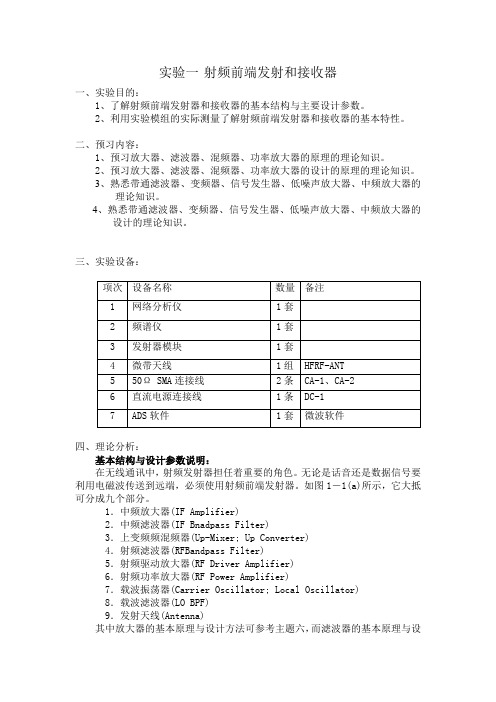
实验一 射频前端发射和接收器
(8)三阶互调截止点( THIRD-ORDER INTERCEPT POINT,IP3)
其中IP3——混频器的输入三阶互调截止点。
PIN——混频器输入端的输入信号的功率。
Δ——混频器输出端中,设计输出信号与内调制(INTER-MODULATION,IM)信号的功率差(dB)
8.载波滤波器(LO BPF)
9.发射天线(Antenna)
其中放大器的基本原理与设计方法可参考主题六,而滤波器的基本原理与设计方法已可参考主题五的说明。至于振荡器的部分,可于主题八与与主题九获得一些参考。天线部分则可由主题十得到概念。 所以,在此单元中将就上变频器部分的基本原理做一说明。并介绍发射器的几个重要设计参数。
除非有特别注明,一般的变频损耗皆按上式定义,即单边带变频耗损( SINGLE-SIDEBAND(SSB) CONVERSION LOSS ), 即只考虑射频输出信号频率为fLO+fIF或fLO-fIF。若是定义为双边带变频损耗(DOUBLE-SIDEBAND(DSB) CONVERSION LOSS), 则比单边带转频损耗低3dB。
6
直流电源连接线
1条
DC-1
7
ADS软件
1套
微波软件
四、理论分析:
基本结构与设计参数说明:
在无线通讯中,射频发射器担任着重要的角色。无论是话音还是数据信号要利用电磁波传送到远端,必须使用射频前端发射器。如图1-1(a)所示,它大抵可分成九个部分。
1.中频放大器(IF Amplifier)
2.中频滤波器(IF Bnadpass Filter)
其中,IP2——混频器的输入二阶互调截止点。(dBm)
- 1、下载文档前请自行甄别文档内容的完整性,平台不提供额外的编辑、内容补充、找答案等附加服务。
- 2、"仅部分预览"的文档,不可在线预览部分如存在完整性等问题,可反馈申请退款(可完整预览的文档不适用该条件!)。
- 3、如文档侵犯您的权益,请联系客服反馈,我们会尽快为您处理(人工客服工作时间:9:00-18:30)。
ECE 1352FAnalog Integrated Circuits IReading Assignment - RF Power AmplifiersPrepared by: Poon, Alan Siu KeiTable of ContentI. Introduction (3)II. Backgrounda. Why Class-F power amplifier? (4)b. Class-F power amplifier operation (5)c. Previous development of Class-F power amplifier (8)III. Present development of Class-F power amplifier (11)a. Theoretical improvement (11)b. Practical improvement (15)IV. Future challenges and focus (20).V. Conclusion (21)References (22)I. IntroductionThe rapid growth of mobile telecommunications services created increasing demand for low-cost, low-power and reduced size and weight equipments. An increasingly higher level of integration is needed to meet these requirements. Thanks to the advancement in deep sub-micron CMOS technology, this is easily achievable for digital signal and low-frequency signal processing. However, in order to reach the final goal of System-on-a-Chip (SoC) solution, the final piece of puzzle is still missing – the RF front end. In fact, being the most power hungry component of the RF front end, it is widely known that the RF power amplifier (PA) is one of the most critical building blocks in low power SoC integration. Therefore, it is clear that RF PA deserves increased design research to remove the bottleneck of the development of mobile communication devices. Among different classes of PAs, the Class-F topology has been drawing more attention by researchers in the last decade. In this paper, the recent development of Class-F PAs for portable devices will be discussed. In section II, an introduction to Class-F PA operation will be presented. Also, previously developed state of the art Class-F PA systems will be discussed in this section. In section III, current development of Class-F PA will be presented. The future focus and challenges to the development of Class-F PA will be revealed in section IV followed by a conclusion in section V.II. BackgroundIIa. Why Class-F power amplifier?Traditionally, PAs are categorized into different classes according to their historical precedence. Different PA classes can be divided into two major groups: linear and non-linear PAs. Class A, AB, B and C PA are some of the well-known linear PAs, which are distinguished primarily by their bias condition. Linear PAs have the advantage of high linearity that is important for variable envelope modulation schemes (e.g. π/4-QPSK). However, linear amplifiers suffer from poor maximum power efficiency which limits their applications in low-power devices. In practice, an efficiency of only below 20% can be achieved in those systems. In contrast, non-linear PAs (also known as switched mode PAs) can achieve better efficiency. As suggested by its name, non-linear PAs have poor linearity performance. Nevertheless, it is still acceptable for constant envelope modulation schemes (e.g. FSK). To overcome the problem of linearity to adapt to variable envelope systems, many linearization techniques have been proposed for non-linear amplifiers [1,2]. Therefore, due their high efficiency and the development of linearization techniques, non-linear PAs have received more attention over linear topologies in mobile communication in the last decade. Class E and F are the most common classes of non-linear PAs. In comparison, Class E PA requires fast switching driver signal that is not required for Class-F PA. Moreover, because of relatively large switch stresses to active devices, Class E amplifiers do not scale gracefully with the trend toward lower-power technology with lower breakdown voltage [1:Thomas Lee]. For these reasons,Class-F PA has drawn more attention for its easier implementation and better integration with sub-micron CMOS technology.IIb. Class-F power amplifier operationA Class-F PA uses a output filter to control the harmonic content of its drain-voltage or drain-current waveforms, thereby shaping them to reduce power dissipation by the transistor and thus to increase efficiency. An example of the output voltage and current waveform of an ideal Class-F PA is shown in Fig. 1 [3].Fig. 1. Example of a Class-F power amplifier.In the figure, it is noticed that the output voltage waveform is a square wave while the drain current is a half-rectified sinusoid. From the output waveforms it is also noticed that in the ideal case, there is no overlapping between the output voltageand current waveform. This suggests that the maximum achievable powerefficiency of the PA is 100%, since there is no power loss in the output waveform[4]. To accomplish this behavior, the active device has a bias point at the cutoff region for switching operation. Also, from Fourier analysis, it is known that the voltage square waveform only has the fundamental and odd harmonics, while the half-rectified current waveform only has the fundamental and even harmonics [4]. Therefore, the load must present an open or short at odd or even harmonics, respectively. A classical Class-F PA demonstrating these characteristics isshown in Fig. 2 [3], in which the output network consists of a quarter-wavelength transmission line and a parallel-tuned LC output tank. The output tank is tuned to resonance at the fundamental frequency (i.e. the carrier frequency).Fig. 2. A Class-F power amplifier with quarter-wavelength transmission line andparallel-tuned output.Recall that for a quarter-wavelength transmission line, the input impedance isLo in Z Z Z 2= (1)The impedance seen by the drain can be easily found from this simple equation. At fundamental frequency, the drain sees a pure resistive load of R L =Z L , since the output tank is open circuit. The tank is a short at all frequencies away from the fundamental. At even harmonics, the transmission line appears to be a half-wavelength line to the drain. We know that for half-wavelength line, the input impedance is Z in =Z L . Therefore, the drain sees a short at all even harmonics, which would result in a half-rectified sinusoid current output as desired. Conversely, at odd harmonics, since the output tank still appears as a short, according to equation (1) the drain sees an open circuit. That is,Open ShortZ Z o in ==2. If the transistor is assumed to act as a switch, the output network will guarantee that all of the drain voltage will see an open and hence a square wave would be resulted as desired [4]. Therefore, the ideal Class-F output waveform can be achieved by this simple circuit. Note that the same ideal maximum efficiency of 100% can also be achieved by producing a square wave current and half-rectified sinusoid voltage at the output [3]. An example of such implementation using a quarter-wavelength transmission line with series-tuned tank is shown in Fig. 3 [3].Fig. 3. A Class-F power amplifier with quarter-wavelength transmission line and series-tuned output.IIc. Previous development of Class-F power amplifierDue to its simple operation principles, little researches have been done on revolving the actual architecture of Class-F PA. What the researchers and developers have been doing is simply reproduce and adapt the Class-F PA architecture in difference fabrication processes and technology and try to improve the efficiency by fine tuning the loading network. In this section, several state of the art Class-F PAs implemented in CMOS technology that are previously developed will be discussed.Although the topology discussed in last section is elegant, the transmission line may be inconveniently long or even inapplicable in fully on-chip integration. Furthermore, the ideal case of infinite impedance at odd harmonics other than the fundamental are undermined in practice by the output capacitance of thetransistor [4]. Therefore, Class-F PAs are usually implemented using finite number of parallel resonant filters connected in series in the loading network to approximate the effect of transmission line. A plot of phase angle vs. relative voltage level is shown in Fig. 4 [5] that demonstrates how the output voltage of a third order network approximates an ideal square wave. An example of suchFundamentalOverall waveformThird harmonicFig. 4. Phase angle vs. relative voltage of an ideal third order network.configuration is shown in Fig. 5 [3]. In Fig. 5, the loading network only consists of parallel resonant filters tuned to the fundamental and third harmonic components. This configuration is called third harmonic peaking [5]. The output voltage and current waveform is also shown in the figure. It is obvious that there is little overlap between the output voltage and current waveform, which causes power dissipation. Theoretically, an ideal third harmonic peaking network can achieve maximum efficiency of more than 80% [3]. Thus, it is shown that the use ofloading network tuned to finite number of harmonics can eliminate the use of transmission line while obtaining respectable efficiency.Fig. 5. Example of a third harmonic peaking Class-F power amplifier.A fully on-chip third harmonic peak Class-F amplifier was implemented in 0.8µm CMOS technology with 3V supply in [6]. The schematic of the circuit is shown in Fig 6. The circuit consists of two stages. The first stage is designed to have maximum gain and the second stage is matched to have maximum efficiency. All of the matching and tuning networks of the PA are accomplished on chip with MOS capacitor and spiral inductors. The implemented PA can only achieve a output power of 20dBm with an efficiency of 16%. The poor efficiency is mainly due to the lossy on-chip spiral inductors of the 0.8µm CMOS technology. From the performance of the design, we can see that there are still lots of space for improvement on power efficiency when design fully on-chip CMOS PA.V out V inFig. 6. Schematic of a two-stage Class-F power amplifier.III. Present development of Class-F power amplifierThe growing demand of low-power mobile communication devices speed up the development of Class-F PA. Recently, both theoretical and practical advancements have been made in this hot area of research. In the first part of this section, new theoretical development on the subject will be presented. Then in the second part, some practical improvements on the implementation of Class-F PA in CMOS technology that has been achieved by researchers will be discussed.IIIa. Theoretical improvementAlthough the Class-F topology has became a popular technique for improving the efficiency of RF PA, the impact of using different numbers of harmonics remains only partially understood. As a consequence, some researches have been conducting researches to investigate the upper limits of output power andefficiency as functions of the number of harmonics used in PA [3, 7, 8, 9]. This allows the designer to make reasonable tradeoff between output networkcomplexity and efficiency since both size and power consumption is important factor when designing mobile communication devices.The best approximation of a square waveform or half-rectified sinusoid out a finite number of harmonics is called the maximally flat waveform [8]. In order to obtain a maximally flat waveform, appropriate coefficients (or relative magnitude) of different harmonic components must be determined. To determine these coefficient values, the drain voltage and current waveforms are expressed as summation of their harmonics:...)5sin()3sin(sin )(530++++=θθθθm m m DD D V V V V vand...)4cos()2cos(sin )(4230+−+−=θθθθm m m DD D I I I I iwhere θ=ωt and ω is the fundamental frequency of the desired output signal. The coefficients of fundamental component can be related to dc component by basic waveform parameters γV ,γ I , δV and δI as:dcIV Dmzx dcI m DDV Dmzx DDV m I i I I V v V V δγδγ====00 ………. (4) Having the voltage and current output described by the above expressions, it is possible to determine the harmonic coefficients of a maximally flat waveform by adjusting their values so that the derivatives of the waveform are zero at themaximum and/or minimum voltage or current. Note that the highest order of derivatives depends on the highest order of harmonics. Since it is known that the voltage waveform reaches its maximum and minimum values at θ = π/2 and 3π/2, we can substitute these angles into the derivatives and solve for the basic waveform parameters for the odd harmonic voltage wave. Similarly, the current waveform parameters can be obtained by knowing it reaches its maximum and minimum values at θ = 3π/2 and π/2. The resulting harmonic coefficients calculated in [7] for odd and even harmonics are summarized in Table 1 and Table 2.Harmonics δV γV = V0m / V DD V3m / V0m V5m / V0m1 2 1 ~~ ~~3 2 1.1547 0.1667 ~~5 2 1.0515 ~~ -0.06183+5 2 1.2071 0.2323 0.0607∞ 2 4 / π = 1.273 4 / 3π = 0.424 4 / 5π = 0.255 Table 1. Maximally flat voltage waveform coefficients for ODD harmonics. Harmonics δI γI = I0m / I dc I2m / I0m I4m / I0m1 2 1 ~~ ~~2 2.9142 1.4142 0.3540 ~~4 2.1863 1.0824 ~~ -0.09572+4 3 1.5 0.3890 0.0556∞π = 3.142 π / 2 = 1.571 2 / 3 = 0.667 2 / 15 = 0.133 Table 2. Maximally flat current waveform coefficients for EVEN harmonics. After determining the harmonic coefficients for maximally flat waveform, we are ready to calculate the maximum output power and efficiency of maximally flat waveforms with different number of harmonics. The output power isRV R V P DD V m O 222220γ== ……….(5) where R is the impedance seen by the drain at the fundamental frequency. The DC-input power isR V R V V I V I V P IDD V I m DD I m DD dc DD i γγγγ200= = ==. ……..(6) Finally, the efficiency of the amplifier is2I V iO P P γγη== ……….(7) and the maximum output power isIV I V I V D D out i v P P δδηδδγγ===2max max max . ……….(8) By substituting the harmonic coefficients in Table 1 and 2 into equation (7) and(8), we can calculate the maximum efficiency and output power of Class-F PA with different number of harmonics. The results obtained in [7] are summarized in Table 3. The same set of results is also plotted in bar chart as shown in Fig. 7.Efficiency, ηMax. current harmonic, m Max. voltage harmonic, n=1 Max. voltage harmonic, n=3 Max. voltage harmonic, n=5 Max. voltage harmonic, n=∞1 0.5 0.5774 0.6033 0.63702 0.7071 0.8165 0.8532 0.90034 0.7497 0.8656 0.9045 0.9545∞ π / 4 = 0.7850.9069 0.9477 1 Maximum output power, P O0.125 0.1443 0.1508 0.159Table 3. Maximum efficiency and power output of Class-F power amplifiers withdifferent number of harmonics.From Fig. 7, Class-F PA designers can easily make the appropriate tradeoff between the complexity and efficiency of the amplifier. This is very useful to designers since both size and power consumption of the PA are important factors when designing modern mobile communication devices. In summary, the result of this research is very helpful for designers to have more in-depth understanding of the characteristics of Class-F PA with finite number of harmonics.Fig. 7. Efficiency and maximum output power of maximally flat waveform with different number of harmonics (n).IIIb. Practical improvementOther than the theoretical improvement that has been made in the development of Class-F PA as presented in the previous part, many researchers have been concentrating on the actual implementation of Class-F PAs in deep sub-micron CMOS technology. In this section, an innovative improvement in implementing a high efficiency Class-F PA in deep sub-micron CMOS technology achieved by a researcher in [10] will be presented.In the RF domain, it is not easy to raise the efficiency of PA by even a few percents, especially implement in CMOS technology. One of the major challenges of implementing Class-F PAs in CMOS is its low oxide breakdown voltage. The problem of low oxide breakdown voltage limits the supply voltage to the amplifier, which directly limits the maximum output power and efficiency of the amplifier. To overcome this problem, a new configuration for Class-F PA was proposed in [10] and the schematic of the circuit is shown in Fig. 8.Thick gate oxideThin gate oxideFig. 8. Schematic of a two-stage Class-F power amplifier.Different from to conventional Class-F PA, this new configuration places a thick oxide (80Å) transistor M2 in cascode to the conventional transistor M1. The gate of M2 is biased at 3V, which allows the output node to sustain 7V without damaging the transistor. The thin gate transistor M1 is now protected by M2 with no threat to oxide breakdown. Since dual gate oxide transistors are widely available in deep sub-micron CMOS technologies, it is not considered a specialprocess requirement. However, note that the higher supply voltage is gained at that cost of lower efficiency because M2 acts as a resistor in series with the output. Also, the cascode transistor M2 reduces the output voltage swing of the PA which is not desirable.Fig. 9. (a) Induction-tuned load PA driver; (b) Reduced angle (φ) V g waveform;(c) CMOS inverter driver; (d) V g waveform of CMOS inverter driver. Another special feature of the new configuration in Fig. 8 is the use of a CMOS inverter as the pre-driver as compared to convention inductor tuned pre-driver as shown in Fig. 9 [10]. In conventional PAs, problem exists when operating with reduced conduction angles for higher efficiency. Under this condition, the input sine wave amplitude must be increased for maximum output current in conventional Class-F PAs using inductor tuned pre-drivers. This results in negative voltage swing that is not an issue for GaAs MESFET, but a major problem for CMOS. The negative voltage swing can potentially forward bias the drain junction diode. More importantly, since the output voltage peaks at themost negative input, this circuit will increase the peak voltage across the gate oxide of M1 and worsen the already severe problem of low oxide breakdown voltage. Thus, the researchers proposed to use a CMOS inverter pre-driver to solve this problem so that it always have non-negative voltage swing. In addition, using a square wave driver can improve the efficiency of PAs, because square wave input can switch the transistor between cut-off and saturation regions more quickly than a sine wave input. The drawback of using a CMOS inverter driver is reduction in linearity, which is not a problem for constant envelope modulation schemes.By employing the features discussed in the last two paragraphs, the new Class-F PA configuration demonstrates respectable performance when it was implemented in deep sub-micron CMOS technology. In [10], the circuit was successfully implemented on-chip in a 0.2µm CMOS technology with a dual supply voltage of 1.8V and 3V. Operating at 900MHz, the PA can deliver a maximum output power of 1.5W with an efficiency of 43%. This is a significant improvement in performance as compared to the previous fully on-chip PA described in section IIc. The result of this work shows that higher power is achievable with deep sub-micron CMOS technology despite the low oxide breakdown voltage.IV. Future challenges and focusBy comparing the maximum efficiency of an ideal case (~80%-90%) to that of the so-called state of the art circuit discussed in this paper (~50%), obviously there is still a lot of space for improvement in deep sub-micron CMOS Class-F PAs. Undoubtedly, researchers will continue to try to improve the efficiency of CMOS Class-F PAs by fine tuning the load network and using higher quality passive and active elements. In addition, some recent research papers reveal the possibility of improving Class-F PAs efficiency by proper shaping of the input driving signal [11]. Other than that, the development of power control of PAs is becoming another popular research area. This is because while mobile communication devices dissipate higher power during active operation, much smaller power is needed during stand-by operation mode. Thus, good power control to of PAs can greatly reduce the overall efficiency and power consumption of devices. Furthermore, in order to achieve the goal of putting the entire mobile handsets circuits in a single chip, the integration of RF front end module with the low-frequency or baseband DSP module remains the one of the most challenging research area. For example, the substrate noise from the DSP module will greatly degrade the performance of the RF front end module.V. ConclusionIn this paper, some recent developments of Class-F power amplifiers are presented, especially on their integration with deep sub-micron CMOS technology. However, these advancements are just a little step in the development of a compact, low cost and efficient power amplifier. Although the concept of Class-F topology has been proposed for several decades, its characteristics are still not fully understood and a systematic design procedure is still yet to be defined. In addition, many issues are still needed to be resolved before the goal of System-on-a-Chip can be realized. Nevertheless, the rapid growing demand of mobile communication devices will be a good catalyst for the development of RF power amplifiers and a real SoC solution will hit the market very soon in the future.References[1] Gary Hau, Takeshi B. Nishimura and Naotaka Iwata, “A high efficientlinearized wide-band CDMA handset power amplifier based onpredistortion under various bias conditions,” IEEE Transaction onMicrowave Theory and Techniques, Vol. 49, No. 6, pp.1194-1201, June2001.[2] Steve Hung-Lung Tu and Chris Toumazou, “Low-distortion CMOScomplementary Class E RF tuned power amplifiers,” IEEE Trans. onCircuits and Systems-I: Fund. Theory and Applications, Vol. 47, No. 5, pp.774-779, May 2000.[3] F. H. Raab, “An introduction to Class-F power amplifies,” RF Design, Vol.19, No. 5, pp. 79-84, May 1996.[4] Thomas H. Lee, The Design of CMOS Radio-Frequency IntegratedCircuits, Cambridge, 1999.[5] Chris Trask, “Class-F amplifier loading networks: a unified designapproach,” IEEE MTT-S Dig., Anaheim, CA, pp. 351-354, June 1999. [6] Y. J. E. Chen, M. Hamai, H. Heo, A. Sutono, S. Yoo and J. Laskar, “RFpower amplifier integration in CMOS technology,” IEEE MTT-S Dig., pp.545-548, 2000.[7] F. H. Raab, “Maximum efficiency and output of Class-F power amplifiers,”IEEE Trans. on Microwave Theory and Techniques, Vol. 49, No. 6, pp.1162-1166, June 2001.[8] F. H. Raab, “Class-F power amplifiers with maximally flat waveforms,”IEEE Trans. on Microwave Theory and Techniques, Vol. 45, No. 11,pp.2007-2012, Nov. 1997.[9] F. H. Raab, “Class-F power amplifiers with reduced conduction angles,”IEEE Trans. on Broadcasting, Vol. 44, No. 4, pp.455-459, Dec. 1998. [10] Timothy C. Kuo and Bruce B. Lusignan, “A 1.5W Class-F RF poweramplifier in 0.2µm CMOS technology,” ISSCC, Session 10, WirelessBuilding Blocks-I, pp. 154-155, Feb. 2001.[11] A. N. Rudiakova and V. G. Krizhanovski, “Driving waveforms for Class-Fpower amplifiers, “ IEEE MTT-S Dig., pp. 473-476, 2000.[12] F. H. Raab, “Class-E, Class-C, and Class-F power amplifiers based upona finite number of harmonics,” IEEE Trans. on Microwave Theory andTechniques, Vol. 49, No. 8, pp. 1462-1468, Aug. 2001.[13] Gary Hau, Takeshi B. Nishimura, Naotaka Iwata, “High efficiency, widedynamic range variable gain and power amplifier MMICs for wide-bandCDMA handsets,” IEEE Microwave and Wireless Components Letters,Vol. 11, No. 1, pp. 13-15, Jan. 2001.21。