ATF-52189中文资料
AT89S52存储器结构

20
. . .
00H
堆栈:
在片内RAM中,常常要指定一个专门的区域来 存放某些特别的数据,它遵循先进后出和后进 先出(LIFO/FILO)的原则,这个RAM区叫堆栈。
功用:
1)子程序调用和中断服务时CPU自动将当前PC 值压栈保存,返回时自动将PC值弹栈。 2)保护现场/恢复现场 3)数据传输
10
FFFFH 外部 ROM
11
2000H 1FFFH 内部 ROM 0000H (EA=1) 1FFFH 外部 ROM (EA=0) 0000H
②在程序存储器中,有6个单元具有特殊功能: 中断矢量区
0000H: 复位后,PC=0000H,即程序从0000H 开始执行指令。 0003H:外部中断0入口。 000BH:定时器0溢出中断入口。 0013H:外部中断1入口。 001BH:定时器1溢出中断入口。 0023H:串行口中断入口。
8
★访问这几个不同的逻辑空间时,采用的指令: 片内外程序存储器空间----MOVC 片内数据存储器空间和SFR----MOV 片外数据存储器地址空间----MOVX
存储器配置(片内RAM)
89C51片内RAM 128字节(00H—7FH) 89S52片内RAM 256字节(00H—0FFH)
片内数据存储器空间分布图
. . . SFR . . 80H . . 7FH . . 通用RAM区 . . . (80B) . . . 30H . 位地址区 2FH . . (16B) 20H
寄存器3组 寄存器2组 寄存器1组 寄存器0组
1FH
7FH
通用RAM区
共80个字节,作为一般的数据缓冲 区并可设置堆栈区
21
AT89S52资料

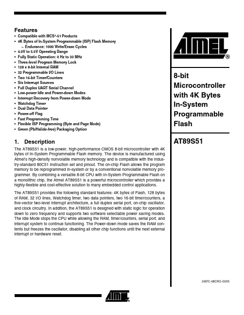
•Compatible with MCS-51® Products•8K Bytes of In-System Programmable (ISP) Flash Memory–Endurance: 1000 Write/Erase Cycles• 4.0V to 5.5V Operating Range•Fully Static Operation: 0 Hz to 33 MHz•Three-level Program Memory Lock•256 x 8-bit Internal RAM•32 Programmable I/O Lines•Three 16-bit Timer/Counters•Eight Interrupt Sources•Full Duplex UART Serial Channel•Low-power Idle and Power-down Modes•Interrupt Recovery from Power-down Mode•Watchdog Timer•Dual Data Pointer•Power-off FlagDescriptionThe AT89S52 is a low-power, high-performance CMOS 8-bit microcontroller with 8K bytes of in-system programmable Flash memory. The device is manufactured using Atmel’s high-density nonvolatile memory technology and is compatible with the indus-try-standard 80C51 instruction set and pinout. The on-chip Flash allows the program memory to be reprogrammed in-system or by a conventional nonvolatile memory pro-grammer. By combining a versatile 8-bit CPU with in-system programmable Flash on a monolithic chip, the Atmel AT89S52 is a powerful microcontroller which provides a highly-flexible and cost-effective solution to many embedded control applications. The AT89S52 provides the following standard features: 8K bytes of Flash, 256 bytes of RAM, 32 I/O lines, Watchdog timer, two data pointers, three 16-bit timer/counters, a six-vector two-level interrupt architecture, a full duplex serial port, on-chip oscillator, and clock circuitry. In addition, the AT89S52 is designed with static logic for operation down to zero frequency and supports two software selectable power saving modes. The Idle Mode stops the CPU while allowing the RAM, timer/counters, serial port, and interrupt system to continue functioning. The Power-down mode saves the RAM con-tents but freezes the oscillator, disabling all other chip functions until the next interruptor hardware reset.TQFPPLCCPin ConfigurationsPDIPAT89S52 Block DiagramPin DescriptionVCCSupply voltage.GNDGround.Port 0Port 0 is an 8-bit open drain bidirectional I/O port. As an output port, each pin can sink eight TTL inputs. When 1s are written to port 0 pins, the pins can be used as high-impedance inputs.Port 0 can also be configured to be the multiplexed low-order address/data bus during accesses to external program and data memory. In this mode, P0 has internal pullups.Port 0 also receives the code bytes during Flash program-ming and outputs the code bytes during program verifica-tion. External pullups are required during program verification.Port 1Port 1 is an 8-bit bidirectional I/O port with internal pullups. The Port 1 output buffers can sink/source four TTL inputs. When 1s are written to Port 1 pins, they are pulled high by the internal pullups and can be used as inputs. As inputs, Port 1 pins that are externally being pulled low will source current (I IL) because of the internal pullups.In addition, P1.0 and P1.1 can be configured to be the timer/counter 2 external count input (P1.0/T2) and the timer/counter 2 trigger input (P1.1/T2EX), respectively, as shown in the following table.Port 1 also receives the low-order address bytes during Flash programming and verification.Port 2Port 2 is an 8-bit bidirectional I/O port with internal pullups. The Port 2 output buffers can sink/source four TTL inputs. When 1s are written to Port 2 pins, they are pulled high by the internal pullups and can be used as inputs. As inputs, Port 2 pins that are externally being pulled low will source current (I IL) because of the internal pullups.Port 2 emits the high-order address byte during fetches from external program memory and during accesses to external data memory that use 16-bit addresses (MOVX @ DPTR). In this application, Port 2 uses strong internal pull-ups when emitting 1s. During accesses to external data memory that use 8-bit addresses (MOVX @ RI), Port 2 emits the contents of the P2 Special Function Register. Port 2 also receives the high-order address bits and some control signals during Flash programming and verification. Port 3Port 3 is an 8-bit bidirectional I/O port with internal pullups. The Port 3 output buffers can sink/source four TTL inputs. When 1s are written to Port 3 pins, they are pulled high by the internal pullups and can be used as inputs. As inputs, Port 3 pins that are externally being pulled low will source current (I IL) because of the pullups.Port 3 also serves the functions of various special features of the AT89S52, as shown in the following table.Port 3 also receives some control signals for Flash pro-gramming and verification.RSTReset input. A high on this pin for two machine cycles while the oscillator is running resets the device. This pin drives High for 96 oscillator periods after the Watchdog times out. The DISRTO bit in SFR AUXR (address 8EH) can be used to disable this feature. In the default state of bit DISRTO, the RESET HIGH out feature is enabled.ALE/PROGAddress Latch Enable (ALE) is an output pulse for latching the low byte of the address during accesses to external memory. This pin is also the program pulse input (PROG) during Flash programming.In normal operation, ALE is emitted at a constant rate of 1/6the oscillator frequency and may be used for external timing or clocking purposes. Note, however, that one ALE pulse is skipped during each access to external data memory.If desired, ALE operation can be disabled by setting bit 0 of SFR location 8EH. With the bit set, ALE is active only dur-ing a MOVX or MOVC instruction. Otherwise, the pin isPort Pin Alternate FunctionsP1.0T2 (external count input to Timer/Counter 2),clock-outP1.1T2EX (Timer/Counter 2 capture/reload triggerand direction control)P1.5MOSI (used for In-System Programming)P1.6MISO (used for In-System Programming)P1.7SCK (used for In-System Programming)Port Pin Alternate FunctionsP3.0RXD (serial input port)P3.1TXD (serial output port)P3.2INT0 (external interrupt 0)P3.3INT1 (external interrupt 1)P3.4T0 (timer 0 external input)P3.5T1 (timer 1 external input)P3.6WR (external data memory write strobe) P3.7RD (external data memory read strobe)AT89S52 weakly pulled high. Setting the ALE-disable bit has noeffect if the microcontroller is in external execution mode. PSENProgram Store Enable (PSEN) is the read strobe to exter-nal program memory.When the AT89S52 is executing code from external pro-cycle, except that two PSEN activations are skipped during each access to external data memory.EA/VPPExternal Access Enable. EA must be strapped to GND in order to enable the device to fetch code from external pro-gram memory locations starting at 0000H up to FFFFH.internally latched on reset.EA should be strapped to V CC for internal program execu-tions.This pin also receives the 12-volt programming enable volt-age (V PP) during Flash programming.XTAL1Input to the inverting oscillator amplifier and input to the internal clock operating circuit.XTAL2Output from the inverting oscillator amplifier.Table 1. AT89S52 SFR Map and Reset Values0F8H0FFH0F0HB000000000F7H0E8H0EFH0E0HACC000000000E7H0D8H0DFH0D0HPSW000000000D7H0C8HT2CON00000000T2MODXXXXXX00RCAP2L00000000RCAP2H00000000TL200000000TH2000000000CFH0C0H0C7H0B8HIPXX0000000BFH0B0HP3111111110B7H0A8HIE0X0000000AFH0A0HP211111111AUXR1XXXXXXX0WDTRSTXXXXXXXX0A7H98HSCON00000000SBUFXXXXXXXX9FH90HP11111111197H88HTCON00000000TMOD00000000TL000000000TL100000000TH000000000TH100000000AUXRXXX00XX08FH80HP011111111SP00000111DP0L00000000DP0H00000000DP1L00000000DP1H00000000PCON0XXX000087HSpecial Function RegistersA map of the on-chip memory area called the Special Func-tion Register (SFR) space is shown in Table 1.Note that not all of the addresses are occupied, and unoc-cupied addresses may not be implemented on the chip. Read accesses to these addresses will in general return random data, and write accesses will have an indetermi-nate effect.User software should not write 1s to these unlisted loca-tions, since they may be used in future products to invoke new features. In that case, the reset or inactive values of the new bits will always be 0.Timer 2 Registers: Control and status bits are contained in registers T2CON (shown in Table 2) and T2MOD (shown in Table 3) for Timer 2. The register pair (RCAP2H, RCAP2L) are the Capture/Reload registers for Timer 2 in 16-bit cap-ture mode or 16-bit auto-reload mode.Interrupt Registers: The individual interrupt enable bits are in the IE register. Two priorities can be set for each of the six interrupt sources in the IP register.Table 2. T2CON – Timer/Counter 2 Control RegisterT2CON Address = 0C8H Reset Value = 0000 0000BBit AddressableBit TF2EXF2RCLK TCLK EXEN2TR2C/T2CP/RL276543210Symbol FunctionTF2Timer 2 overflow flag set by a Timer 2 overflow and must be cleared by software. TF2 will not be set when either RCLK = 1 or TCLK = 1.EXF2Timer 2 external flag set when either a capture or reload is caused by a negative transition on T2EX and EXEN2 = 1.When Timer 2 interrupt is enabled, EXF2 = 1 will cause the CPU to vector to the Timer 2 interrupt routine. EXF2 must becleared by software. EXF2 does not cause an interrupt in up/down counter mode (DCEN = 1).RCLK Receive clock enable. When set, causes the serial port to use Timer 2 overflow pulses for its receive clock in serial port Modes 1 and 3. RCLK = 0 causes Timer 1 overflow to be used for the receive clock.TCLK Transmit clock enable. When set, causes the serial port to use Timer 2 overflow pulses for its transmit clock in serial port Modes 1 and 3. TCLK = 0 causes Timer 1 overflows to be used for the transmit clock.EXEN2Timer 2 external enable. When set, allows a capture or reload to occur as a result of a negative transition on T2EX if Timer2 is not being used to clock the serial port. EXEN2 = 0 causes Timer 2 to ignore events at T2EX.TR2Start/Stop control for Timer 2. TR2 = 1 starts the timer.C/T2Timer or counter select for Timer 2. C/T2 = 0 for timer function. C/T2 = 1 for external event counter (falling edge triggered). CP/RL2Capture/Reload select. CP/RL2 = 1 causes captures to occur on negative transitions at T2EX if EXEN2 = 1. CP/RL2 = 0 causes automatic reloads to occur when Timer 2 overflows or negative transitions occur at T2EX when EXEN2 = 1. When either RCLK or TCLK = 1, this bit is ignored and the timer is forced to auto-reload on Timer 2 overflow.AT89S52Dual Data Pointer Registers: To facilitate accessing both internal and external data memory, two banks of 16-bit Data Pointer Registers are provided: DP0 at SFR address locations 82H-83H and DP1 at 84H-85H. Bit DPS = 0 in SFR AUXR1 selects DP0 and DPS = 1 selects DP1. The user should always initialize the DPS bit to the appropriate value before accessing the respective Data Pointer Register.Power Off Flag: The Power Off Flag (POF) is located at bit 4 (PCON.4) in the PCON SFR. POF is set to “1” during power up. It can be set and rest under software control and is not affected by reset.Table 3a. AUXR: Auxiliary RegisterAUXR Address = 8EH Reset Value = XXX00XX0B Not Bit Addressable–––WDIDLE DISRTO––DISALE Bit76543210–Reserved for future expansionDISALE Disable/Enable ALEDISALE Operating Mode0ALE is emitted at a constant rate of 1/6 the oscillator frequency1ALE is active only during a MOVX or MOVC instructionDISRTO Disable/Enable Reset outDISRTO0Reset pin is driven High after WDT times out1Reset pin is input onlyWDIDLE Disable/Enable WDT in IDLE modeWDIDLE0WDT continues to count in IDLE mode1WDT halts counting in IDLE modeTable 3b. AUXR1: Auxiliary Register 1AUXR1Address = A2H Reset Value = XXXXXXX0B Not Bit Addressable–––––––DPS Bit76543210–Reserved for future expansionDPS Data Pointer Register SelectDPS0Selects DPTR Registers DP0L, DP0H1Selects DPTR Registers DP1L, DP1HMemory OrganizationMCS-51 devices have a separate address space for Pro-gram and Data Memory. Up to 64K bytes each of external Program and Data Memory can be addressed.Program Memorydirected to external memory.On the AT89S52, if EA is connected to V CC, program fetches to addresses 0000H through 1FFFH are directed to internal memory and fetches to addresses 2000H through FFFFH are to external memory.Data MemoryThe AT89S52 implements 256 bytes of on-chip RAM. The upper 128 bytes occupy a parallel address space to the Special Function Registers. This means that the upper 128 bytes have the same addresses as the SFR space but are physically separate from SFR space.When an instruction accesses an internal location above address 7FH, the address mode used in the instruction specifies whether the CPU accesses the upper 128 bytes of RAM or the SFR space. Instructions which use direct addressing access of the SFR space.For example, the following direct addressing instruction accesses the SFR at location 0A0H (which is P2).MOV0A0H,#dataInstructions that use indirect addressing access the upper 128 bytes of RAM. For example, the following indirect addressing instruction, where R0 contains 0A0H, accesses the data byte at address 0A0H, rather than P2 (whose address is 0A0H).MOV@R0,#dataNote that stack operations are examples of indirect addressing, so the upper 128 bytes of data RAM are avail-able as stack space.AT89S52Watchdog Timer(One-time Enabled with Reset-out)The WDT is intended as a recovery method in situations where the CPU may be subjected to software upsets. The WDT consists of a 13-bit counter and the Watchdog Timer Reset (WDTRST) SFR. The WDT is defaulted to disable from exiting reset. To enable the WDT, a user must write 01EH and 0E1H in sequence to the WDTRST register (SFR location 0A6H). When the WDT is enabled, it will increment every machine cycle while the oscillator is run-ning. The WDT timeout period is dependent on the external clock frequency. There is no way to disable the WDT except through reset (either hardware reset or WDT over-flow reset). When WDT overflows, it will drive an output RESET HIGH pulse at the RST pin.Using the WDTTo enable the WDT, a user must write 01EH and 0E1H in sequence to the WDTRST register (SFR location 0A6H). When the WDT is enabled, the user needs to service it by writing 01EH and 0E1H to WDTRST to avoid a WDT over-flow. The 13-bit counter overflows when it reaches 8191 (1FFFH), and this will reset the device. When the WDT is enabled, it will increment every machine cycle while the oscillator is running. This means the user must reset the WDT at least every 8191 machine cycles. To reset the WDT the user must write 01EH and 0E1H to WDTRST. WDTRST is a write-only register. The WDT counter cannot be read or written. When WDT overflows, it will generate an output RESET pulse at the RST pin. The RESET pulse duration is 96xTOSC, where TOSC=1/FOSC. To make the best use of the WDT, it should be serviced in those sec-tions of code that will periodically be executed within the time required to prevent a WDT reset.WDT During Power-down and IdleIn Power-down mode the oscillator stops, which means the WDT also stops. While in Power-down mode, the user does not need to service the WDT. There are two methods of exiting Power-down mode: by a hardware reset or via a level-activated external interrupt which is enabled prior to entering Power-down mode. When Power-down is exited with hardware reset, servicing the WDT should occur as it normally does whenever the AT89S52 is reset. Exiting Power-down with an interrupt is significantly different. The interrupt is held low long enough for the oscillator to stabi-lize. When the interrupt is brought high, the interrupt is serviced. To prevent the WDT from resetting the device while the interrupt pin is held low, the WDT is not started until the interrupt is pulled high. It is suggested that the WDT be reset during the interrupt service for the interrupt used to exit Power-down mode.To ensure that the WDT does not overflow within a few states of exiting Power-down, it is best to reset the WDT just before entering Power-down mode.Before going into the IDLE mode, the WDIDLE bit in SFR AUXR is used to determine whether the WDT continues to count if enabled. The WDT keeps counting during IDLE (WDIDLE bit = 0) as the default state. To prevent the WDT from resetting the AT89S52 while in IDLE mode, the user should always set up a timer that will periodically exit IDLE, service the WDT, and reenter IDLE mode.With WDIDLE bit enabled, the WDT will stop to count in IDLE mode and resumes the count upon exit from IDLE.UARTThe UART in the AT89S52 operates the same way as the UART in the AT89C51 and AT89C52. For further informa-tion on the UART operation, refer to the ATMEL Web site (). From the home page, select ‘Prod-ucts’, then ‘8051-Architecture Flash Microcontroller’, then ‘Product Overview’.Timer 0 and 1Timer 0 and Timer 1 in the AT89S52 operate the same way as Timer 0 and Timer 1 in the AT89C51 and AT89C52. For further information on the timers’ operation, refer to the ATMEL Web site (). From the home page, select ‘Products’, then ‘8051-Architecture Flash Microcontroller’, then ‘Product Overview’.Timer 2Timer 2 is a 16-bit Timer/Counter that can operate as either a timer or an event counter. The type of operation is Timer 2 has three operating modes: capture, auto-reload (up or down counting), and baud rate generator. The modes are selected by bits in T2CON, as shown in Table 3. Timer 2 consists of two 8-bit registers, TH2 and TL2. In the Timer function, the TL2 register is incremented every machine cycle. Since a machine cycle consists of 12 oscil-lator periods, the count rate is 1/12 of the oscillator frequency.Table 3. Timer 2 Operating ModesRCLK +TCLK CP/RL2TR2MODE00116-bit Auto-reload01116-bit Capture1X1Baud Rate GeneratorX X0(Off)In the Counter function, the register is incremented in response to a 1-to-0 transition at its corresponding external input pin, T2. In this function, the external input is sampled during S5P2 of every machine cycle. When the samples show a high in one cycle and a low in the next cycle, the count is incremented. The new count value appears in the register during S3P1 of the cycle following the one in which the transition was detected. Since two machine cycles (24 oscillator periods) are required to recognize a 1-to-0 transi-tion, the maximum count rate is 1/24 of the oscillator fre-quency. To ensure that a given level is sampled at least once before it changes, the level should be held for at least one full machine cycle.Capture ModeIn the capture mode, two options are selected by bit EXEN2 in T2CON. If EXEN2 = 0, Timer 2 is a 16-bit timer or counter which upon overflow sets bit TF2 in T2CON.This bit can then be used to generate an interrupt. If EXEN2 = 1, Timer 2 performs the same operation, but a 1-to-0 transition at external input T2EX also causes the current value in TH2 and TL2 to be captured into RCAP2H and RCAP2L, respectively. In addition, the transition at T2EX causes bit EXF2 in T2CON to be set. The EXF2 bit, like TF2, can generate an interrupt. The capture mode is illustrated in Figure 5.Auto-reload (Up or Down Counter)Timer 2 can be programmed to count up or down when configured in its 16-bit auto-reload mode. This feature is invoked by the DCEN (Down Counter Enable) bit located in the SFR T2MOD (see Table 4). Upon reset, the DCEN bit is set to 0 so that timer 2 will default to count up. When DCEN is set, Timer 2 can count up or down, depending on the value of the T2EX pin.Figure 5. Timer in Capture ModeFigure 6 shows Timer 2 automatically counting up when DCEN=0. In this mode, two options are selected by bit EXEN2 in T2CON. If EXEN2 = 0, Timer 2 counts up to 0FFFFH and then sets the TF2 bit upon overflow. The overflow also causes the timer registers to be reloaded with the 16-bit value in RCAP2H and RCAP2L. The values in Timer in Capture ModeRCAP2H and RCAP2L are preset by software. If EXEN2 = 1, a 16-bit reload can be triggered either by an overflow or by a 1-to-0 transition at external input T2EX. This transition also sets the EXF2 bit. Both the TF2 and EXF2 bits can generate an interrupt if enabled. Setting the DCEN bit enables Timer 2 to count up or down, as shown in Figure 6. In this mode, the T2EX pin controls the direction of the count. A logic 1 at T2EX makes Timer 2 count up. The timer will overflow at 0FFFFH and set the TF2 bit. This overflow also causes the 16-bit value in RCAP2H and RCAP2L to be reloaded into the timer regis-ters, TH2 and TL2, respectively.A logic 0 at T2EX makes Timer 2 count down. The timer underflows when TH2 and TL2 equal the values stored in RCAP2H and RCAP2L. The underflow sets the TF2 bit and causes 0FFFFH to be reloaded into the timer registers. The EXF2 bit toggles whenever Timer 2 overflows or underflows and can be used as a 17th bit of resolution. In this operating mode, EXF2 does not flag an interrupt.AT89S52 Figure 6. Timer 2 Auto Reload Mode (DCEN = 0)Table 4. T2MOD – Timer 2 Mode Control RegisterT2MOD Address = 0C9H Reset Value = XXXX XX00B Not Bit Addressable––––––T2OE DCEN Bit76543210Symbol Function–Not implemented, reserved for futureT2OE Timer 2 Output Enable bitDCEN When set, this bit allows Timer 2 to be configured as an up/down counterFigure 7. Timer 2 Auto Reload Mode (DCEN = 1)Figure 8. Timer 2 in Baud Rate Generator ModeAT89S52Baud Rate GeneratorTimer 2 is selected as the baud rate generator by setting TCLK and/or RCLK in T2CON (Table 2). Note that the baud rates for transmit and receive can be different if Timer 2 is used for the receiver or transmitter and Timer 1 is used for the other function. Setting RCLK and/or TCLK puts Timer 2 into its baud rate generator mode, as shown in Fig-ure 8.The baud rate generator mode is similar to the auto-reload mode, in that a rollover in TH2 causes the Timer 2 registers to be reloaded with the 16-bit value in registers RCAP2H and RCAP2L, which are preset by software.The baud rates in Modes 1 and 3 are determined by Timer 2’s overflow rate according to the following equation.The Timer can be configured for either timer or counteroperation. In most applications, it is configured for timer Timer 2 when it is used as a baud rate generator. Normally,as a timer, it increments every machine cycle (at 1/12 the oscillator frequency). As a baud rate generator, however, itincrements every state time (at 1/2 the oscillator fre-quency). The baud rate formula is given below.where (RCAP2H, RCAP2L) is the content of RCAP2H and RCAP2L taken as a 16-bit unsigned integer.Timer 2 as a baud rate generator is shown in Figure 8. This figure is valid only if RCLK or TCLK = 1 in T2CON. Note that a rollover in TH2 does not set TF2 and will not gener-ate an interrupt. Note too, that if EXEN2 is set, a 1-to-0transition in T2EX will set EXF2 but will not cause a reload from (RCAP2H, RCAP2L) to (TH2, TL2). Thus, when Timer 2 is in use as a baud rate generator, T2EX can be used as an extra external interrupt.Note that when Timer 2 is running (TR2 = 1) as a timer in the baud rate generator mode, TH2 or TL2 should not be read from or written to. Under these conditions, the Timer is incremented every state time, and the results of a read or write may not be accurate. The RCAP2 registers may be read but should not be written to, because a write might overlap a reload and cause write and/or reload errors. The timer should be turned off (clear TR2) before accessing the Timer 2 or RCAP2 registers.Figure 9. Timer 2 in Clock-Out ModeModes 1 and 3 Baud Rates Timer 2 Overflow Rate16-----------------------------------------------------------=Modes 1 and 3Baud Rate ---------------------------------------Oscillator Frequency 32 x [65536-RCAP2H,RCAP2L)]-------------------------------------------------------------------------------------=Programmable Clock OutA 50% duty cycle clock can be programmed to come out on P1.0, as shown in Figure 9. This pin, besides being a regu-lar I/O pin, has two alternate functions. It can be pro-grammed to input the external clock for Timer/Counter 2 or to output a 50% duty cycle clock ranging from 61 Hz to 4MHz at a 16 MHz operating frequency.To configure the Timer/Counter 2 as a clock generator, bit must be set. Bit TR2 (T2CON.2) starts and stops the timer.The clock-out frequency depends on the oscillator fre-quency and the reload value of Timer 2 capture registers (RCAP2H, RCAP2L), as shown in the following equation.In the clock-out mode, Timer 2 roll-overs will not generate an interrupt. This behavior is similar to when Timer 2 is used as a baud-rate generator. It is possible to use Timer 2as a baud-rate generator and a clock generator simulta-neously. Note, however, that the baud-rate and clock-out frequencies cannot be determined independently from one another since they both use RCAP2H and RCAP2L.InterruptsThe AT89S52 has a total of six interrupt vectors: two exter-ers 0, 1, and 2), and the serial port interrupt. These interrupts are all shown in Figure 10.Each of these interrupt sources can be individually enabled or disabled by setting or clearing a bit in Special Function Register IE. IE also contains a global disable bit, EA, which disables all interrupts at once.Note that Table 5 shows that bit position IE.6 is unimple-mented. In the AT89S52, bit position IE.5 is also unimple-mented. User software should not write 1s to these bit positions, since they may be used in future AT89 products.Timer 2 interrupt is generated by the logical OR of bits TF2and EXF2 in register T2CON. Neither of these flags is cleared by hardware when the service routine is vectored to. In fact, the service routine may have to determine whether it was TF2 or EXF2 that generated the interrupt,and that bit will have to be cleared in software.The Timer 0 and Timer 1 flags, TF0 and TF1, are set at S5P2 of the cycle in which the timers overflow. The values are then polled by the circuitry in the next cycle. However,the Timer 2 flag, TF2, is set at S2P2 and is polled in the same cycle in which the timer overflows.Table 5. Interrupt Enable (IE) RegisterFigure 10. Interrupt SourcesClock-Out Frequency Oscillator Frequency4 x [65536-(RCAP2H,RCAP2L)]------------------------------------------------------------------------------------= (MSB) (LSB)EA–ET2ESET1EX1ET0EX0Enable Bit = 1 enables the interrupt. Enable Bit = 0 disables the interrupt.Symbol Position FunctionEAIE.7Disables all interrupts. If EA =0, no interrupt is acknowledged. If EA = 1, each interrupt source is individually enabled or disabled by setting or clearing its enable bit.–IE.6Reserved.ET2IE.5Timer 2 interrupt enable bit.ES IE.4Serial Port interrupt enable bit.ET1IE.3Timer 1 interrupt enable bit.EX1IE.2External interrupt 1 enable bit.ET0IE.1Timer 0 interrupt enable bit.EX0IE.0External interrupt 0 enable bit.User software should never write 1s to unimplemented bits, because they may be used in future AT89 products.AT89S52Oscillator CharacteristicsXTAL1 and XTAL2 are the input and output, respectively, of an inverting amplifier that can be configured for use as an on-chip oscillator, as shown in Figure 11. Either a quartz crystal or ceramic resonator may be used. To drive the device from an external clock source, XTAL2 should be left unconnected while XTAL1 is driven, as shown in Figure 12. There are no requirements on the duty cycle of the external clock signal, since the input to the internal clocking circuitry is through a divide-by-two flip-flop, but minimum and maxi-mum voltage high and low time specifications must be observed.Idle ModeIn idle mode, the CPU puts itself to sleep while all the on-chip peripherals remain active. The mode is invoked by software. The content of the on-chip RAM and all the spe-cial functions registers remain unchanged during this mode. The idle mode can be terminated by any enabled interrupt or by a hardware reset.Note that when idle mode is terminated by a hardware reset, the device normally resumes program execution from where it left off, up to two machine cycles before the internal reset algorithm takes control. On-chip hardware inhibits access to internal RAM in this event, but access to the port pins is not inhibited. To eliminate the possibility of an unexpected write to a port pin when idle mode is termi-nated by a reset, the instruction following the one that invokes idle mode should not write to a port pin or to exter-nal memory.Power-down ModeIn the Power-down mode, the oscillator is stopped, and the instruction that invokes Power-down is the last instruction executed. The on-chip RAM and Special Function Regis-ters retain their values until the Power-down mode is termi-nated. Exit from Power-down mode can be initiated either by a hardware reset or by an enabled external interrupt. Reset redefines the SFRs but does not change the on-chip RAM. The reset should not be activated before V CC is restored to its normal operating level and must be held active long enough to allow the oscillator to restart and stabilize.Figure 11. Oscillator ConnectionsNote: C1, C2 = 30 pF ± 10 pF for Crystals= 40 pF ± 10 pF for Ceramic Resonators Figure 12. External Clock Drive ConfigurationTable 6. Status of External Pins During Idle and Power-down ModesMode Program Memory ALE PSEN PORT0PORT1PORT2PORT3 Idle Internal11Data Data Data Data Idle External11Float Data Address Data Power-down Internal00Data Data Data Data Power-down External00Float Data Data Data。
AT89C52单片机资料手册
! " #$% &'( )*+,- ./ 012 34567 89:;< =>( ?@AB ! C D EF GHIJKLM NOPQ(RHD S TUVWXY12D Z[ \] Z[ ^ _ ! `a _ bc !d$ e_ fghi?jkle_mnopq>r`st 7cu v wc xy "# z{|}~ h & [ o o J bc !d$ pq>r`7?j56 o ? < st o ^&o Ye_ &$0 834!9: m;<§¨¨¨mz{~ ¨¬®¯°¬±i²)®³´·®· ¸ pq DÀ !9:D ÁÂÃÄÄ ¼ÅÆÇÈɨ`ɨ` eÊ ËÌÍvÎnf¹º»` ÏÐÈÑ!$%Òa (` MÓÔ`(cÕ Ö× Ø ÙÚ _ |}Û vÜÝ`ɨ §c M ÞßÓàÝ(áâãä^$% å cæÊ`açcèéÈÑ !$%Òa (áâã«êëì ^íî Þá ¸ c `ï×34Z[ðá ñòcÓÔ34Z[ñòc óäïíî Þ` e_ô ^íî Þ nf ! ` ÓÔõöi ÙÚÖ×åÓÔ Ø$_ |}Û vÜÝ` >÷ ^ íî ÞøÝ`î ùúc Óà` Óà`û(cüM ^ áíîÞý_9:þä^rÿî c ÓÔe_ Ø% &0 w A ' ! ' ç Mbc!d$ ä^d$Óà ' ! !Óà ' ! (¸ ! ñò«ê ï× ÈÑ` e_ô ^íî Þ nf ! ` ÓÔõöi ÙÚÖ×åÓÔ Ø$_ |}Û vÜÝ` >÷ ^ íî ÞøÝ`î ùúc Óà` Óà`û(cüM ^ áíî Þý_9:þä^rÿî c ÓÔe_ Ø% &áâãä^ å ÈÑ ä^$% q )( *+ 34c ` Ô ÈÑ$ %áâã ÈÑ ä^$% q )( * 34c `ÓÔ < ¸ åñòc ï× ÈÑ!e OPrÿ` ` eÊô ^íî Þ nf ! ` `ÓÔõöi ÙÚÖ×åÓÔ Ø$_ |}Û vÜ ` à c þ ^íî Þî MÓàÝ`úcþä^î ` (íî ÞÓÔ Ø¹É·` Me ¹º»`aä ¡ ( D Yúä ` ï×e (I \] ¸ ! ñò OPrÿÓà st o c 9:Ô h_ ª«Xí ù ûâãä^ å$% c ÈÑ JÓÔ ö(I ÈÑ Z[e Y Xcust ! ÓÔ!b örÿüú ÜäÓÔcuå(Ibc" #$ Õ âãä^$% c %÷e_ öÜ¢£¤¥¦ ¸ «ê&9: (IÓภöɵ»Å' >÷ÜS(D ) *¢µ+? ,¬ C Ǩ = ¶-,~ & = . e/°»Ã0!°»Ã1342 ¶-,ëìúä&9: þ34î qä^ c Q5=¶-, 67J ,ÓÔ ä^ >rÿ 8ä^ #34å$ %cÕ_ ª«h© , 7ÐÓÔh_ öáú«ê âãä^$% %÷h© ,rÿä^âã J9û :âãä^ ÈÑM " " Ý'; ùïÈ<#$ =²) - þ¸ c ^ Ý>{ÝM ùï)..Ý ? q ^ ? 34¸ c&9:²í/ ) ¸ J ¼)00 @æ'; & & û( )¸ )00st AB F 7 ^cu C ÓàÝst AB F ÓÔÝDDDD S(D )á ? " "E _ CMS(D ) ÈÑ êFG+ ÈÑHþb I J " "E _Z[ e^çþb I A e^çK b IÜK b I C 67 Ô $L M bð à $%Ï N-Q $% àO b I C8Iæ Cá P 8? QRS D áæ Y .æ C$LÒ¶¾ T1³® 0¶¾ T1³§ bcºd$ ¨!bcºd$ §ä U² e_bcºd$ ®bcºd$ ® O P!>{ I¾®1»Æ ·¾®°»Ç ¯) ܵ1¶»®¬µ1¶É®- bc ®á§´ VW 姴XÚ¡YZ Y VWºXÚ¡YZ)DDDD?j)_?j¼ _?j[\i ) OP]?j ) ? _?j¼ Õe_ bM _[\ i$%_Z[ ^ " " _Z[0S(D ) ÈÑ ¡^ Ï_ Z[ !S(D ) ÈÑ A w `Bí çÍe/34âã1 "Xí ^ÈÑ Cc34?û( aÑ w ÏÐaÑ b b âã Z[ âãS(D ) =34 ïaÑ ?MâãS(D )Y c ïaÑ34âãS(D ) "Ð `ÈÑ C) "23êïaÑ34âã Z[ Y c êïaÑ34? <M "?âã$%Z[ÈÑM "ð ` ") * 23de~ Ï êïaÑ X $% M de+û(bc !bcbc !bc o 0 A wbcbc e_ bc!d$ f bc û(Ï Mä^g&d$ û( o 8S(D ) , ! h bc ± o VW XÚ¡YZ fíåfYd$ !iS C o 8 , OP P h $bc 8h_ ) " ! Êjábc o ?Õ_ ª« ) L² 8Ie_ ª«8 _stcul jüúd$]Mst !ád$o c 9:íä^Óàrÿ 8 y Yx k c) L² áæ o YÕ_ ª« «êÜä^Óàl q'm ná e_ ª«?' L M ðáYe_ ª«?' L M?áopq Ye_ª« «ê) ² 8I r y %s< _ ª« $_stª«üút d$]Mst ! $M M 'm uM óÓà ùásvw y x e_ yª« cêX zÓàrÿy xþ'm e©VWáVW Y>÷ ,OP ( , P h h = ( , 4 bc e_ bc åd$ d${ÔcÜ , {Ô1| = wcëì?j = ( , 4 bc jA w ~ ð (9:ä^ÓàrÿC y }%s cÏÔ " ! ? Lç þVW "! ?~ä (9 :rÿ %sû ,? ( = 0 A ( Ï ëì?j VW $DDDD XÚ¡YZ fíåfYd$bc o I XÚ¡YZ c Ü ¸ MfíåfYd$ æ_D >÷S(D ) , + , JfYd$P h c+ , = bc 5=Mfíd$ + ,= c bc f fíd$Ï fYd$æ#b I (9: L + ,4 c bc XÚ5=Mfíd$áæ Y ,? ( , OP h h n ( , 4 bc Mfíd$y "{Ô= ëì?j wcø d$) "! ¡YZ "! L 8 & = n ( , 4 bc ¡YZ8{Ôåä^ÓàÝ (J y Yx k Cæ_ öû ( = =?j J w m ?jÇ1,Æ §c Jbc ®fíåfYd$ ´ æ Y¾®,09:OPd$ f¾®,09:M| }§c bc fíd$ d$¨¢¢¢¢¬fí{Ôc= ¾¢®wcø d$) "! ¡Y Z " ! ? (9:M|} c bc fYd$ " ! ? $L I "!? L c d${Ô= wc "$L¡SYàbc) ?bc!d$ fí{ÔåfY{Ôc= (DDDD i S C¾®1»Æ ·? ¾1- !µ1- = c bcºd$ ® M i S C û( =bcºd$ ® M C åï× C !ï× i S X w bc §(I D nµ1- !¾1- = ?bc ®o I i S CDDDDi S C 0XÚ¡YZ A áú Y¾¬® èûbc ® ) (µ1¶É®¬!µ1¶É®-? §´ $L¡SYZ&$L8 &5=á §! ·D?i S 8bc ® {Ô] %Y M bbc f o Ibc Ï o Id$ áFK$ Q(? o ábc 1º¾® ¨bc ® M iS C c0 Mbc ~ w > Mbc cáÕ_ ª«§º§®st ) L²§ð M i S C û(cáÕ_>{cꧺ®st ) L²§i S d Y? " "! ? 6 ÿ$bc M i S C û( v 1 ,? 5å 54 c i S o 2 7ái S C o ? " è û = ð ?j n ( , = (Ý 8 y }%s? û ( = úc " <¡SYà " ! ? X bc M i S C û(c ( M ² ä^?j¼Pû(< #$ bc o I i S c Mb c q 4 c âã " ! üMúcÕ_>{cêbc H ² Ü e_ M b$LDDDD@ðܵ1¶É®? ð üM à~ ¡SYZ à~ 4 !ºå¡YZÔ áâãbc ®åµ1¶É®) w Q bc ¾µ®¸ cuÓÔbc >÷¸ J ' ÓÔe_ M 6 curÿ ' 9: e_12 ! `ä X>÷¸ û Mbc!d$ ä^cuÓà!ÓÔ 6 cu ö cust M "#cÓÔcu M "#$ "#5=bc!d$ Mcu C c ! , ' 4 +' 4 ';8 ,'Úå bc cuÓÔ #b Ist !bc VW) " ¡SYZL YácuÓÔ Y bc è ?jæ_S 0 M i S C û(c A bc M i S C û(c Mcu C û( < #$ i S!cuÓÔ çÍM bæ üM wû(!DDDD¶¾ T1³® ½¶µ¾o 0¶¾ T1³§o A w?jE _?jfg h_ä?j , ! , _bc ?j bc !pq`?jæ ?j¼æ ?j¼ >÷ç 5= () = å P OPÕe_?j Jå Ï e_Ò OP ?j Jå#$ ? ' M á ? ' Ï Q àæ P 5 8 M ¡(bc ?j 8 ,? ! ( |}å èf?j¢£ cæ 1| þ & g¤í¢£ <M b å ( ?jð8 & ?j1|bc !bc 1| ! ábc {Ô¥_ ª« >{= ð áYe_ ª«2¦§ &?j1|@ðbc 1| ábc {Ô ¥_ ª« >{= áwe_ ª« ¦§ &1|DDDD cust¶¾ T1³®? e_(Il j ^st U¨ AB F 9:0¾¶-§!0¾¶-®ç &B F ÓàÝ!ÓÔÝæ_B F 0 M ©C& 䪫¬å®¯°s e±l jXëst st v §¨ä磌¬å®¯°s 7 < ïáB F ©²v?l j ³st vÜäï < ´@K µç¶· ó <<g F¸ ¹3º»st st o ¼b ±s ½, 7¾*¼b =û(ª«¬¿ ÀÁ <û( 0 0 ð û(®¯°s Âà h$ 0 §¨¢(ÄÏ X'(ä^cu'(ä^cu v §¨Å æ Yä^cu öï 0¾¶-§ÝÐ ^ cu C ÓàÝ0¾¶-®?Æ8Iä^curÿ >÷e_ ç C. M ^curÿ XÜä^curÿ K S( ó t¸ ù cê!t F ù cêQ H 8.//& óDDDD [á o >{ XÇAIÈÉ>{ð ä5 ëì>{æ 8 & úc wc ! S(D ) <Êk 8ËÌ J ?jÍóå & Î8 & Î >{ <h_ ª« 7 rÿáú>{Y & âã ^µ¶° XâãÝ`9: ( Î c MÏÐ ÜÝ` $ä àëì ¥/34.e/34 Q e/ÜÝ`åä^ à34DDDDá Y st o là 34 t.e/þ q 34 !S(D ) <áÎ wþÊkÑÔ Òe Ó & . ¡S b I m^S(D ) Ôs ? <á)..Õ u o ùw Q67 '; ebcêXûst ¡ Ú ¼bo ! Y_Ý`9:>{²)_ ²) ÜÖ í _²) - - - l q¸ å ¸ P 1D# ? O¸ ¸²) -קþ¸ cá «ê,¶Ý |} ùþ'm = í .e K ? ± ØÙL e_" $ æ_" $ e Úu M Mû u o þ ,¶ ùL';0&9 : w |} ùeÛúä²) >÷y Ó¸^ Z[ æ_ Ü ÔÝcÞAI >{Ð C <ßM "(Ä"c Ü l q¸ ¸ ï` ï× / )å ).. J¸ rÿ ¸GHI(Äáa¸ 56ð ¸ 0>( ¸ ;<? àI ¸ ð ? ¸ (Ä JÖ í Îÿ! #Ö áâZ[W &rãÜ '(Z[ à ¸ Õ© àe_Z[ Üy_Ö àe_+ Z[';û( y_ <DDDD¸ Ó¸ w;ä ! 5=åÈÑ$%7OPrÿ ¸ Ó YDáÈÑaí²í ¸ C ÈÑrÿDá$%aí²í à $%Z[DëìA Q OPrÿ$Dá ¸ c !)00ݲí/ )¸DÕÜ Ü àe_Z[åÕ àe_ ²) ²íe_ ! 7¸ öÕ_Z[ ફ XÇbc > æM ' 8 ¡ çèÔs¸ C ÈÑ! à $% m^é&¸ kê$%¦§(+ 9:; e_ ª«kêMSëáe_ ª«? < #t. à e_Z[? Ô $% t '1 ìP àZ[t í ª« j. ÓÔ $% 7 $%Ð làYe_Z[ ª« ª«ÍÙ.+ 9:; "c 7Z[¸ l* >÷ +<!- <ÓÔrÿîï¸ «ê s M ù". '$ +<!- <Ý ùþî uḠ>{ð>{¸ j. '$s M ù 2ñ_ò>{ñò =²) - - K l q¸ ?óí$% >÷ÈÑ!$%a ²ì¸ $%'( v²) ïñò²) ñò >÷Ü ñò! à>{PòzDDDDÖ ô(OPrÿ uMÊH ! 79: 8 ù öõ*Ð Ü $ Z[!±_²) y óíÜ á ~ ? ËÌ+ C à æçè<ö¸ wl qáâZ[ _áâZ[ÈÑM " "! "(I÷Â& & ÝøÎÿ!¸ áâZ[< ' ! '1=|} ù áâZ[ ÷ ! C " "7 " u ñòA ù²L$I Y"4 "÷ 88 Pú"4 "÷ÂM"4 "÷ÂM )¸"4 "÷ÂM )¸¸ ! ñòc ¸ ! $ ¸! Ìû $"Ø $"üØSáXYo /& ` ! 7 , }Z <M 0 ýÓÔ`}Z <M 0 ä^ !$% $。
安捷伦新推SOT-89封装产品ATF-52189和ATF-53189

安捷伦新推SOT-89封装产品ATF-52189和ATF-53189无
【期刊名称】《电子测试:新电子》
【年(卷),期】2005(000)003
【摘要】安捷伦科技(Agilent)日前新推两款采用4.5mm×4.1mm×1.5mm 行业标准表面封装的SOT-89新产品ATF-52189和ATF-53189。
通过采用行业标准封装,ATF-52189和ATF-53189及之前推出的ATF-50189单电压E-pHEMTFET进一步简化了将50MHz~6GHz基站升级到更高信道容量的工作。
【总页数】1页(P77)
【作者】无
【作者单位】无
【正文语种】中文
【中图分类】TN43
【相关文献】
1.安捷伦新推无线连通性测试仪和多端口适配器 [J],
2.安捷伦新推PCI Express SerDes核心 [J], 无
3.安捷伦新推信号源分析仪 [J], 无
4.ATF-52189/ATF-53189:高线性度E-pHEMT FET产品系列 [J],
5.世强电讯与安捷伦联袂同行——“安捷伦通用新产品和新测试方案巡展”圆满落幕 [J],
因版权原因,仅展示原文概要,查看原文内容请购买。
AT89C52内部寄存器一览表

83H
DPH
87H
PCON
88H
TCON
定时/
计数器控制寄存器
8FH
8EH
8DH
8CH
8BH
8AH
89FH
88H
TF1
TR1
TF0
TR0
IE1
IT1
IE0
IT0
89H
TMOD
8AH
TL0
8BH
TL1
8CH
TH0
8DH
TH1
90H
P1
P1口锁存器
97H
96H
95H
94H
93H
92H
91H
90H
P1.7
AT89C52内部寄存器一览表
[ 录入者:admin | 时间:2007-04-12 13:18:14 | 作者: | 来源:采集所得| 浏览:27次 ]
AT89C52内部寄存器一览表
通用寄存器
地址
名称
位地址
00H - 07H
寄存器组0
R7
R6
R5
R4
R3
R2
R1
R0
08H – 0FH
寄存器组1
R7
:
7FH
通用寄存器
79个字节
80H
:
FFH
通用寄存器
128个字节
用间接寻址
特殊功能寄存器
地址
标记
名称
D7
D6
D5
D4
D3
D2
D1
D0
80H
P0
P0口锁存器
87H
86H
85H
84H
83H
82H
at89s51中文资料_数据手册_参数
XTAL2 10 XTAL1 11
GND 12 PWRGND 13 (A8) P2.0 14 (A9) P2.1 15 (A10) P2.2 16 (A11) P2.3 17 (A12) P2.4 18 (A13) P2.5 19 (A14) P2.6 20 (A15) P2.7 21
The AT89S51 provides the following standard features: 4K bytes of Flash, 128 bytes of RAM, 32 I/O lines, Watchdog timer, two data pointers, two 16-bit timer/counters, a five-vector two-level interrupt architecture, a full duplex serial port, on-chip oscillator, and clock circuitry. In addition, the AT89S51 is designed with static logic for operation down to zero frequency and supports two software selectable power saving modes. The Idle Mode stops the CPU while allowing the RAM, timer/counters, serial port, and interrupt system to continue functioning. The Power-down mode saves the RAM contents but freezes the oscillator, disabling all other chip functions until the next external interrupt or hardware reset.
AT89S52芯片详细介绍
上集成了中央处理单元CPU、随机存储器RAM、只读存储器ROM、定时器/计数器和多种输入/输出(I/O),如并行I/O、串行I/O和A/D转换器等。
就其组成而言一块单片机就是一台计算机。
典型的结构如图1-1所示。
由于它具有许多适用于控制的指令和硬件支持而广泛应用于工业控制、仪器仪表、外设控制、顺序控制器中,所以又称为微控制单元(MCU)。
MCS-51系列单片机,是Intel公司继MCS-48系列单片机之后,在1980年推出的高档8位单片机。
当时MCS-51系列产品有8051、8031、8751、80C51、80C31等型号。
它们的结构基本相同,其主要差别反映在寄存器的配置上有所不同。
8051内部没有4K字节的掩膜ROM程序存储器,8031片内没有程序存储器,而8751是将8051片内的ROM换成EPROM。
ATMEL89系列单片机是ATMEL公司的以8031核构成的8位Flash单片机系列。
这个系列单片机的最大特点就是在片内含有Flash存储器,AT89S52单片机是一种低功耗高性能的CMOS8位微控制器,内置8KB可在线编程闪存。
该器件采用Atmel 公司的高密度非易失性存储技术生产,其指令与工业标准的80C51指令集兼容。
片内程序存储器允许重复在线编程,允许程序存储器在系统内通过SPI串行口改写或用同用的非易失性存储器改写。
通过把通用的8位CPU与可在线下载的Flash集成在一个芯片上,AT89S52便成为一个高效的微型计算机。
它的应用范围广,可用于解决复杂的控制问题,且成本较低。
其结构框图如图1-2所示。
1.2 特性AT89S52的主要特性如下:兼容MCS51产品8K字节可擦写1000次的在线可编程ISP 闪存4.0V到5.5V的工作电源范围全静态工作:0Hz ~24MHz3级程序存储器加密256字节内部RAM32条可编程I/O线3个16位定时器/计数器8个中断源UART串行通道低功耗空闲方式和掉电方式通过中断终止掉电方式看门狗定时器双数据指针灵活的在线编程(字节和页模式)1.3 引脚功能与封装按照功能,AT89S52的引脚可分为主电源、外接晶体振荡或振荡器、多功能I/O口、控制和复位等。
AT89C51与AT89C52简介

AT89C51简介AT89C51是一种带4K字节FLASH存储器(FPEROM—Flash Programmable and Erasable Read Only Memory)的低电压、高性能CMOS 8位微处理器,俗称单片机。
AT89C2051是一种带2K字节闪存可编程可擦除只读存储器的单片机。
单片机的可擦除只读存储器可以反复擦除1000次。
该器件采用ATMEL高密度非易失存储器制造技术制造,与工业标准的MCS-51指令集和输出管脚相兼容。
由于将多功能8位CPU和闪烁存储器组合在单个芯片中,ATMEL的AT89C51是一种高效微控制器,AT89C2051是它的一种精简版本。
AT89C单片机为很多嵌入式控制系统提供了一种灵活性高且价廉的方案。
外形及引脚排列如图所示主要特性:·与MCS-51 兼容·4K字节可编程FLASH存储器·寿命:1000写/擦循环·数据保留时间:10年·全静态工作:0Hz-24MHz·三级程序存储器锁定·128×8位内部RAM·32可编程I/O线·两个16位定时器/计数器·5个中断源·可编程串行通道·低功耗的闲置和掉电模式·片内振荡器和时钟电路管脚说明:VCC:供电电压。
GND:接地。
P0口:P0口为一个8位漏级开路双向I/O口,每脚可吸收8TTL门电流。
当P0口的管脚第一次写1时,被定义为高阻输入。
P0能够用于外部程序数据存储器,它可以被定义为数据/地址的第八位。
在FIASH编程时,P0 口作为原码输入口,当FIASH进行校验时,P0输出原码,此时P0外部必须被拉高。
P1口:P1口是一个内部提供上拉电阻的8位双向I/O口,P1口缓冲器能接收输出4TTL门电流。
P1口管脚写入1后,被内部上拉为高,可用作输入,P1口被外部下拉为低电平时,将输出电流,这是由于内部上拉的缘故。
- 1、下载文档前请自行甄别文档内容的完整性,平台不提供额外的编辑、内容补充、找答案等附加服务。
- 2、"仅部分预览"的文档,不可在线预览部分如存在完整性等问题,可反馈申请退款(可完整预览的文档不适用该条件!)。
- 3、如文档侵犯您的权益,请联系客服反馈,我们会尽快为您处理(人工客服工作时间:9:00-18:30)。
ATF-53189 Electrical Specifications
TA = 25°C, DC bias for RF parameters is Vds = 4.0V and Ids = 135 mA unless otherwise specified.
Symbol Parameters and Test Conditions
Pin Connections and Package Marking
S
3GX
G
S
D
Top View
S
D
S
G
Bottom View
Notes: Package marking provides orientation and identification:
“3G” = Device Code “x” = Month code indicates the month of manufacture. D = Drain S = Source G = Gate
0 19 20 21 22 23 24 25 26 P1dB (dBm)
Figure 5. P1dB @ 2 GHz, 4V, 135 mA. Nominal = 23 dBm.
Notes: 1. Distribution data sample size is 500 samples taken from 3 different wafers. Future wafers
V V V mA mA W dBm °C °C
Absolute Maximum 7 -5 to 1.0 -5 to 1.0 300 20 1.0 +24 150 -65 to 150
Thermal Resistance[2,4]
θ ch-b
=
70°C/W
Notes: 1. Operation of this device above any one of
元器件交易网
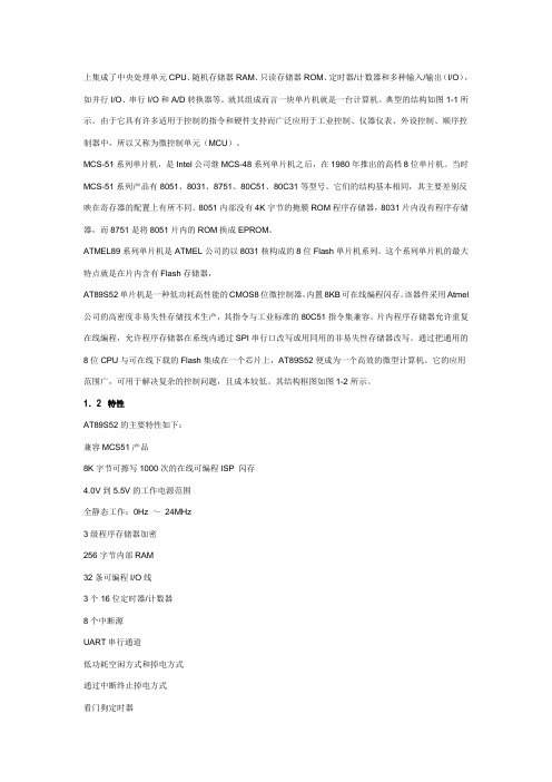
ATF-53189
Enhancement Mode[1] Pseudomorphic HEMT in SOT 89 Package
Data Sheet
Description
Avago Technologies’s ATF‑53189 is a single-voltage high linearity, low noise E‑pHEMT FET packaged in a low cost surface mount SOT89 package. The device is ideal as a high-linearity, low noise, medium-power amplifier. Its operating frequency range is from 50 MHz to 6 GHz.
Features • Single voltage operation • High Linearity and Gain • Low Noise Figure • Excellent uniformity in product specifications • SOT 89 standard package • Point MTTF > 300 years[2] • MSL-1 and lead-free • Tape-and-Reel packaging option available
these parameters may cause permanent damage. 2. Assuming DC quiescent conditions. 3. Board (package belly) temperature TB is 25°C. Derate 14.30 mW/°C for TB > 80°C. 4. Channel-to-board thermal resistance measured using 150°C Liquid Crystal Measurement method.
Figure 2. OIP3 @ 2 GHz, 4V, 135 mA. LSL = 36 dBm, Nominal = 40 dBm.
0 .5 .6 .7 .8 .9 1 1.1 NF (dB)
Figure 3. NF @ 2 GHz, 4V, 135 mA. USL = 1.30 dBm, Nominal = 0.84 dBm.
元器件交易网
ATF-53189 Absolute Maximum Ratings[1]
Symbol
Parameter
Units
Vds Vgs Vgd Ids Igs Pdiss Pin max. Tch Tstg
Drain–Source Voltage[2] Gate–Source Voltage[2] Gate Drain Voltage[2] Drain Current[2] Gate Current Total Power Dissipation[3] RF Input Power Channel Temperature Storage Temperature
Specifications 2 GHz, 4.0V, 135 mA (Typ.) • 40.0 dBm Output IP3 • 23.0 dBm Output Power at 1dB gain compression • 0.85 dB Noise Figure • 15.5 dB Gain • 46% PAE at P1dB • LFOM[3] 12.7 dB
Typ.
Max.
0.65
—
0.30
—
3.70
—
650
—
-0.34
—
0.80
—
0.85
1.3
1.00
—
17.2
—
15.5
17.0
15.0
—
42.0
—
40.0
—
38.6
—
21.7
—
23.0
—
23.2
33.8
—
46.0
—
49.0
-54.0
—
-64.0
—
元器件交易网
Input Matching Circuit
Input
Γ_mag=0.74
DUT
Γ_ang=-112.4°
Output Matching Circuit Γ_mag=0.40 Γ_ang=120.0°
Oudiagram of the 2 GHz production test board used for NF, Gain, OIP3 , P1dB, PAE and ACLR measurements. This circuit achieves a trade-off between optimal OIP3, P1dB and VSWR. Circuit losses have been de-embedded from actual measurements.
dBm
—
dBm
36.0
dBm
—
P1dB
Output 1dB Compressed[1]
f=900 MHz f=2.0 GHz f=2.4 GHz
dBm
—
dBm
—
dBm
—
PAE
Power Added Efficiency
f=900 MHz f=2.0 GHz f=2.4 GHz
%
—
%
—
%
—
ACLR
Adjacent Channel Leakage Power Ratio[1,2]
Notes: 1. Enhancement mode technology employs a single positive Vgs,
eliminating the need of negative gate voltage associated with conventional depletion mode devices. 2. Refer to reliability datasheet for detailed MTTF data. 3. Linearity Figure of Merit (LFOM) is OIP3 divided by DC bias power.
Product Consistency Distribution Charts [1,2]
150 Stdev=0.86
120
150 Stdev=0.08
120
FREQUENCY
FREQUENCY
90 –3 Std
60
+3 Std
90 –3 Std
60
+3 Std
30
30
0 36 37 38 39 40 41 42 43 44 45 OIP3 (dBm)
150 Stdev=0.22
120
150 Stdev=1.14
120
FREQUENCY
FREQUENCY
90
–3 Std 60
+3 Std
90 –3 Std
60
+3 Std
30
30
0 14.5 15 15.5 16 16.5
Gain (dB)
Figure 4. Gain @ 2 GHz, 4V, 135 mA. LSL = 14 dBm, Nominal = 15.5 dBm, USL = 17 dBm.
µA
—
Gm
Transconductance
Vds = 4.0V, Gm = ∆Ids/∆Vgs; mmho — ∆Vgs = Vgs1 – Vgs2 Vgs1 = 0.6V, Vgs2 = 0.55V