【EP3547812A1】PRESSUREAPPLYINGDEVICEFORASWITCHINGMO
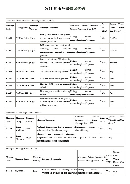
DELL服务器面板指示灯错误代码
Yes
Any
E1222
VCACHE #PwrGd
High
VCACHE # voltage regulator has failed.
AC Cycle or SEL clear
Yes
Any
E1223
VRM #PwrGd
High
VRM # voltage regulator has failed.
Failing device is reseated/replaced/repaired.
Yes
Any
W1228
ROMBห้องสมุดไป่ตู้att< 24 hr
Low
This is a predictive failure warning message telling the user that the PERC5I RAID battery has less then 24 hours of charge left init. Wee provide this message as a warning message to the customer.
System Phase When Event Can Occur?
E1210
CMOSBatt
Low
CMOS battery is missing or the voltage is outside of the allowable range.
Failing device is reseated/replaced/repaired.
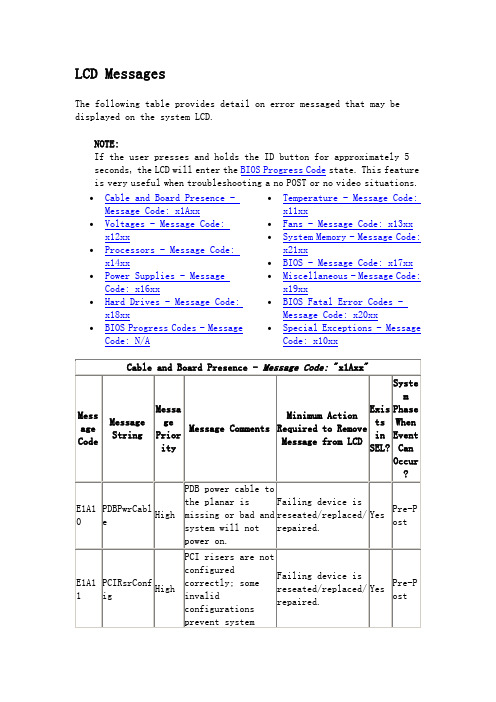
LCD Messages
The following table provides detail on error messaged that may be displayed on the system LCD.
BS EN 12845-2004+A2-2009 固定式消防系统.自动喷水系统设计,安装和维修
BRITISH STANDARD
BS EN 12845:2004 +A2:2009
Incorporating Corrigendum August 2009
Fixed firefighting systems — Automatic sprinkler systems — Design, installation and maintenance
1 2 3 4 4.1 4.2 4.3 4.4 4.4.1 4.4.2 4.4.3 4.4.4 5 5.1 5.1.1 5.1.2 5.2 5.3 5.4 5.5 6 6.1 6.2 6.2.1 6.2.2 6.2.3 6.3 6.3.1 6.3.2 7 7.1 7.2 7.2.1 7.2.2 7.2.3 7.3 7.3.1 7.3.2
介绍 Introduction ................................................................................................................................................. 10
This British Standard was published under the authority of the Standards Policy and Strategy Committee on 16 November 2004
Amendments/corrigenda issued since publication Date 31 July 2009 Comments Implementation of CEN amendment A2:2009 Correction to National foreword
Dell服务器常见故障代码说明
Any
E1116
Temp Memory
High
Memory has exceeded allowable temperature and has been disabled to prevent damage to the components.
AC Cycle or SEL clear
Yes
Any
Voltages - Message Code: "x12xx"
Message Code
Message String
Message Priority
Message Comments
Minimum Action Required to Remove Message from LCD
Exists in SEL?
Exists in SEL?
System Phase When Event Can Occur?
E1A10
PDBPwrCable
High
PDB power cable to the planar is missing or bad and system will not power on.
Failing device is reseated/replaced/repaired.
Yes
Any
E1219
BackplanePwrGd
High
Backplane voltage regulator has failed.
AC Cycle or SEL clear
Yes
Any
E1221
Flex BayPwrGd
High
FlexBayvoltage regulator power good has failed.
OMEGA PV100 电子控制比例阀说明书
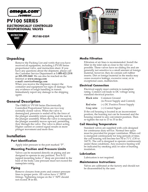
PV100 SERIES ELECTRONICALLY CONTROLLEDPROPORTIONAL VALVESUnpackingRemove the Packing List and verify that you havereceived all equipment, including a PV100 Seriesproportional valve, and instruction sheet. If youhave any questions about the shipment, please callthe Customer Service Department at 1-800-622-2378or 203-359-1660. We can also be reached on theInternet at e-mail:******************When you receive the shipment, inspect thecontainer and equipment for signs of damage. Noteany evidence of rough handling in transit.Immediately report any damage to the shippingagent.General DescriptionThe OMEGA®PV100 Series ElectronicallyControlled Proportional Valves are two-waynormally closed valves. When the valve isdeenergized, pressure is sealed off by the force ofthe plunger assembly return spring and the seal inthe plunger assembly. When the valve is energized,the plunger assembly moves upward, permittingflow through the valve. The valve is direct acting.Higher current or control signal results in moreplunger movement and more flow.InstallationPort IdentificationApply inlet pressure to the port marked “P”.Mounting Position and Pressure Limits Valves can be mounted directly on piping and aredesigned to operate in any position. Two 8-32tapped mounting holes 1⁄4” deep are provided in thebase of the body. Line pressure must not exceed thenameplate rating.PipingRemove closures from ports and connect pressurelines to proper ports. All valves have 1⁄8" NPTFfittings. Tightening torque on the 1⁄8" NPT shouldnot exceed 38 in-lbs.Media FiltrationFiltration of air lines is recommended. Install thefilter in the inlet side as close to the valve aspossible. These valves have no sliding fits and aregenerally not sensitive to a small amount of foreign material, however, they do contain soft rubberinserts. Dirt or foreign material in the media maycause excessive leakage, excessive wear, or inexceptional cases, malfunction.Electrical ConnectionElectrical supply must conform to nameplaterating. Connect coil leads to DC voltage usingstandard electrical practice.Black wire Common Ground(to Power Supply and Control) Red wire(+) DC Positive Power SupplyGray wire(+) Control SignalIf the coil housing is located in an inconvenientposition, the housing nut can be loosened and thehousing rotated to any convenient position. Thenre-tighten the nut to 13 to 35 in-lbs.Coil Housing TemperatureStandard valves are supplied with coils designedfor continuous duty service. Normal free spacemust be provided for proper ventilation. When coil is energized continuously for long periods of time, the coil housing will become hot 54 to 71°C (130 to 160°F). The coil is designed to operate continuously under these conditions. Any excessive heating will be indicated by smoking and/or odor of burninginsulation.LubricationLubrication is not required.Maintenance InstructionsValves are calibrated at the factory and should notbe disassembled by the user.Available ModelsFlow Ranges,SCCM Model Orifice Maximum At Maximum At Number Millimeters Inches C v Pressure Pressure10 PSI PV101-(*).801/320.02200 PSI0-50,0000-8,000 PV102-(*) 1.193/640.045100 PSI0-65,0000-17,000 PV103-(*) 1.591/160.0860 PSI0-75,0000-30,000 PV104-(*) 1.985/640.1240 PSI0-80,0000-45,000 *Specify Control Signal:MA for 4-20 MADC5V for 0-5 VDC10V for 0-10 VDCDimensions2SpecificationsValve Type:2-Way Normally ClosedWetted Parts:Stainless Steel with Viton SealsPower:12-24 VDCPower Consumption:7 Watts MaximumControl Signals:0-5 VDC, 0-10 VDC, 4-20 MADCAmbient Temperature Range:-10 to 50°C(14 to 122°F)Media Temperature Range:-18 to 82°C(0 to 180°F)Linear Control Range:15-85% of Full FlowResponse Time for Complete CycleOff - Full Open - Off:40 msec @ 0 pressure100 msec @ maximum pressureRepeatability:±5% when in operating linear control rangeElectrical Connection:18" color-coded lead wiresWiring:Red DC Power SupplyGray Control Signal (+)Black Common (to Power and Control) Pressure Connections:1⁄8" NPTFEnclosure:General Purpose, NEMA-13It is the policy of OMEGA Engineering, Inc. to comply with all worldwide safety and EMC/EMI regulations that apply. OMEGA is constantly pursuing certification of its products to the European New Approach Directives. OMEGA will add the CE mark to every appropriate device upon certification.The information contained in this document is believed to be correct, but OMEGA accepts no liability for any errors it contains, and reserves the right to alter specifications without notice.WARNING: These products are not designed for use in, and should not be used for, human applications.WARRANTY/DISCLAIMEROMEGA ENGINEERING, INC. warrants this unit to be free of defects in materials and workmanship for a period of 13 months from date of purchase.OMEGA’s WARRANT Y adds an additional one (1) month grace period to the normal one (1) year product warranty to cover handling and shipping time. This ensures that OMEGA’s customers receive maximum coverage on each product.If the unit malfunctions, it must be returned to the factory for evaluation. OMEGA’s Customer Service Department will issue an Authorized Return (AR)number immediately upon phone or written request. Upon examination by OMEGA, if the unit is found to be defective, it will be repaired or replaced at no charge. OMEGA’s WARRANTY does not apply to defects resulting from any action of the purchaser, including but not limited to mishandling,improper interfacing, operation outside of design limits, improper repair, or unauthorized modification. This WARRANTY is VOID if the unit shows evidence of having been tampered with or shows evidence of having been damaged as a result of excessive corrosion; or current, heat, moisture or vibration; improper specification; misapplication; misuse or other operating conditions outside of OMEGA’scontrol. Components in which wear is not warranted, include but are not limited to contact points, fuses, and triacs.OMEGA is pleased to offer suggestions on the use of its various products. However, OMEGA neither assumes responsibility for any omissions or errors nor assumes liability for any damages that result from the use of its products in accordance with information provided by OMEGA, either verbal or written. OMEGA warrants only that the parts manufactured by the company will be as specified and free of defects. OMEGA MAKES NO OTHER WARRANTIES OR REPRESENTATIONS OF ANY KIND WHATSOEVER, EXPRESSED OR IMPLIED, EXCEPT THAT OF TITLE, AND ALL IMPLIED WARRANTIES INCLUDING ANY WARRANTY OF MERCHANTABILITY AND FITNESS FOR A PARTICULAR PURPOSE ARE HEREBY DISCLAIMED. LIMITATION OF LIABILITY : The remedies of purchaser set forth herein are exclusive, and the total liability of OMEGA with respect to this order, whether based on contract, warranty, negligence, indemnification, strict liability or otherwise,shall not exceed the purchase price of the component upon which liability is based. In no event shall OMEGA be liable for consequential,incidental or special damages.CONDITIONS: Equipment sold by OMEGA is not intended to be used, nor shall it be used: (1) as a “Basic Component” under 10 CFR 21 (NRC), used in or with any nuclear installation or activity; or (2) in medical applications or used on humans. Should any Product(s) be used in or with any nuclear installation or activity, medical application, used on humans, or misused in any way, OMEGA assumes no responsibility as set forth in our basic WARRANT Y/DISCLAIMER language, and, additionally, purchaser will indemnify OMEGA and hold OMEGA harmless from any liability or damage whatsoever arising out of the use of the Product(s) in such a manner.Servicing North America:U.S.A.:One Omega Drive, Box 4047ISO 9001 CertifiedStamford, CT 06907-0047Tel: (203) 359-1660FAX: (203) 359-7700e-mail:**************Canada:976 BergarLaval (Quebec) H7L 5A1, Canada Tel: (514) 856-6928FAX: (514) 856-6886e-mail:*************For immediate technical or application assistance:U.S.A. and Canada:Sales Service: 1-800-826-6342 / 1-800-TC-OMEGA ®Customer Service: 1-800-622-2378 / 1-800-622-BEST ®Engineering Service: 1-800-872-9436 / 1-800-USA-WHEN ®TELEX: 996404 EASYLINK: 62968934 CABLE: OMEGAMexico:En Espan ˜ol: (001) 203-359-7803e-mail:*****************FAX: (001) 203-359-7807**************.mxOMEGAnet ®Online Service Internet e-mail***********************Servicing Europe:Benelux:Postbus 8034, 1180 LA Amstelveen, The Netherlands Tel: +31 (0)20 3472121FAX: +31 (0)20 6434643Toll Free in Benelux: 0800 0993344e-mail:*****************Czech Republic:Frystatska 184, 733 01 Karviná, Czech Republic Tel: +420 (0)59 6311899FAX: +420 (0)59 6311114Toll Free: 0800-1-66342e-mail:*****************France:11, rue Jacques Cartier, 78280 Guyancourt, France Tel: +33 (0)1 61 37 2900FAX: +33 (0)1 30 57 5427Toll Free in France: 0800 466 342e-mail:**************Germany/Austria:Daimlerstrasse 26, D-75392 Deckenpfronn, GermanyTel: +49 (0)7056 9398-0FAX: +49 (0)7056 9398-29TollFreeinGermany************e-mail:*************United Kingdom:One Omega Drive, River Bend Technology CentreISO 9002 CertifiedNorthbank, Irlam, Manchester M44 5BD United Kingdom Tel: +44 (0)161 777 6611FAX: +44 (0)161 777 6622Toll Free in United Kingdom: 0800-488-488e-mail:**************.ukRETURN REQUESTS /INQUIRIESDirect all warranty and repair requests/inquiries to the OMEGA Customer Service Department. BEFORE RETURNING ANY PRODUCT (S) T OOMEGA, PURCHASER MUST OBTAIN AN AUTHORIZED RETURN (AR) NUMBER FROM OMEGA’S CUSTOMER SERVICE DEPARTMENT (IN ORDER T O AVOID PROCESSING DELAYS). T he assigned AR number should then be marked on the outside of the return package and on any correspondence.The purchaser is responsible for shipping charges, freight, insurance and proper packaging to prevent breakage in transit.FOR WARRANTY RETURNS, please have the following information available BEFORE contacting OMEGA:1.Purchase Order number under which the product was PURCHASED,2.Model and serial number of the product under warranty, and3.Repair instructions and/or specific problems relative to the product.FOR NON-WARRANTY REPAIRS,consult OMEGA for current repair charges.Have the following information available BEFORE contacting OMEGA:1. Purchase Order number to cover the COST of the repair,2.Model and serial number of the product, and3.Repair instructions and/or specific problems relative to the product.OMEGA’s policy is to make running changes, not model changes, whenever an improvement is possible. T his affords our customers the latest in technology and engineering.OMEGA is a registered trademark of OMEGA ENGINEERING, INC.© Copyright 2004 OMEGA ENGINEERING, INC. All rights reserved. This document may not be copied, photocopied, reproduced, translated, or reduced to any electronic medium or machine-readable form, in whole or in part, without the prior written consent of OMEGA ENGINEERING, INC.。
梅达焊接控制器说明中文版
. .MedWeld6000 中频控制器说明书目录第1章:系统概述 (3)1.1. 简介 (3)1.2. 机器人应用 (3)1.3. 焊接控制器内部 (4)1.4. 规格参数 (4)第2章:控制器开箱 (7)2.1. 检查 (7)2.2. 起吊和移动焊接控制器 (7)2.3. 零部件的破损,遗失 (8)第3章:安全与警告 (10)3.1. 上锁 (10)3.2. 文档中的符号 (10)3.3. MedWeld 6000焊接柜安全问题 (11)第4章:焊接控制器安装 (13)4.1. 安装列表 (13)4.2. 机械安装 (15)4.3. 电气安装 (18)4.4. 程序和软件设置 (19)第5章: 通讯设置 (21)5.1. 关于MedWeld 6000 通讯 (21)5.2. DeviceNet 设置 (22)5.3. Ethernet/IP 设置 (23)5.4. 6000系列处理器LED 指示灯 (24)第6章:焊接程序 (25)6.1. 关于焊接程序 (25)6.2. 编辑一个程序 (28)6.3. 默认程序 (30)第7章:设置参数 (33)7.1. 设置参数 (33)第8章:递增器 (45)8.1. 递增器介绍 (45)8.2. 递增器组 (46)8.3. 在一个焊接程序中打开一个递增器 (47)8.4. 电极修磨 (48)第9章:先进特点 (50)9.1. C系数 (50)9.2. 自动电流补偿焊接 (51)9.3. 自动电压补偿焊接 (52)第10章:故障及诊断 (54)10.1. 故障列表 (54)第11章:维护保养 (63)11.1. 保养明细表 (63)11.2. 备件清单 (63)参考A:I/O列表 (65)1. 灵活的I/O (65)2. 完整的I/O列表(EIP和Fieldbus) (67)3. IO定义 (70)参考B:焊接功能项列表 (76)1. 完整的焊接功能项列表 (76)2. 延时功能项 (80)3. 焊接功能项 (80)4. 坡度功能项 (82)5. I/O功能项 (83)6. 延伸功能项 (84)7. 特殊功能项 (85)第1章:系统概述1.1. 简介MedWeld6000是美国WTC公司最新推出的逆变焊接控制平台。
E-control系统故障中英文对照
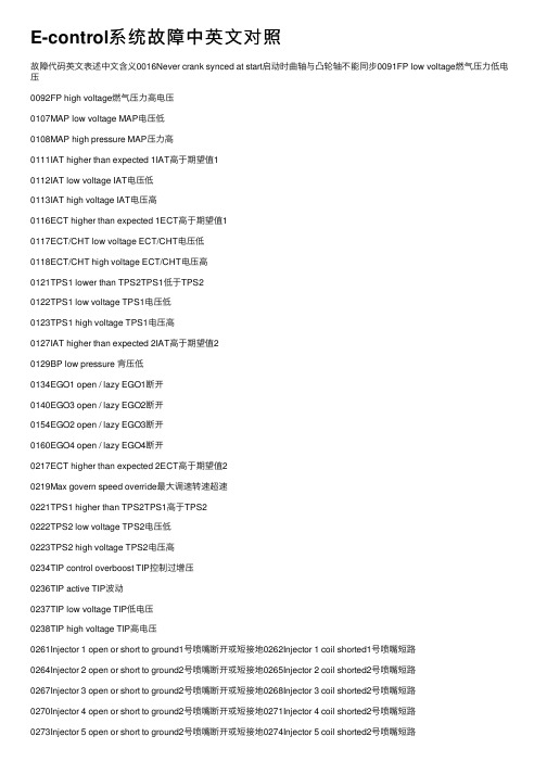
E-control系统故障中英⽂对照故障代码英⽂表述中⽂含义0016Never crank synced at start启动时曲轴与凸轮轴不能同步0091FP low voltage燃⽓压⼒低电压0092FP high voltage燃⽓压⼒⾼电压0107MAP low voltage MAP电压低0108MAP high pressure MAP压⼒⾼0111IAT higher than expected 1IAT⾼于期望值10112IAT low voltage IAT电压低0113IAT high voltage IAT电压⾼0116ECT higher than expected 1ECT⾼于期望值10117ECT/CHT low voltage ECT/CHT电压低0118ECT/CHT high voltage ECT/CHT电压⾼0121TPS1 lower than TPS2TPS1低于TPS20122TPS1 low voltage TPS1电压低0123TPS1 high voltage TPS1电压⾼0127IAT higher than expected 2IAT⾼于期望值20129BP low pressure 背压低0134EGO1 open / lazy EGO1断开0140EGO3 open / lazy EGO2断开0154EGO2 open / lazy EGO3断开0160EGO4 open / lazy EGO4断开0217ECT higher than expected 2ECT⾼于期望值20219Max govern speed override最⼤调速转速超速0221TPS1 higher than TPS2TPS1⾼于TPS20222TPS2 low voltage TPS2电压低0223TPS2 high voltage TPS2电压⾼0234TIP control overboost TIP控制过增压0236TIP active TIP波动0237TIP low voltage TIP低电压0238TIP high voltage TIP⾼电压0261Injector 1 open or short to ground1号喷嘴断开或短接地0262Injector 1 coil shorted1号喷嘴短路0264Injector 2 open or short to ground2号喷嘴断开或短接地0265Injector 2 coil shorted2号喷嘴短路0267Injector 3 open or short to ground2号喷嘴断开或短接地0268Injector 3 coil shorted2号喷嘴短路0270Injector 4 open or short to ground2号喷嘴断开或短接地0271Injector 4 coil shorted2号喷嘴短路0273Injector 5 open or short to ground2号喷嘴断开或短接地0274Injector 5 coil shorted2号喷嘴短路0276Injector 6 open or short to ground2号喷嘴断开或短接地0277Injector 6 coil shorted2号喷嘴短路0279Injector 7 open or short to ground2号喷嘴断开或短接地0280Injector 7 coil shorted2号喷嘴短路0282Injector 8 open or short to ground2号喷嘴断开或短接地0283Injector 8 coil shorted2号喷嘴短路0285Injector 9 open or short to ground2号喷嘴断开或短接地0286Injector 9 coil shorted2号喷嘴短路0288Injector 10 open or short to ground2号喷嘴断开或短接地0289Injector 10 coil shorted2号喷嘴短路0299TIP control underboost TIP控制未增压0336Crank sync noise曲轴输出信号⼲扰0337Crank loss曲轴信号丢失0341Cam sync noise凸轮轴输出信号⼲扰0342Cam loss凸轮轴信号丢失0502Roadspeed input loss of signal0524Oil pressure low机油压⼒低0562voltage low电瓶电压低0563voltage high电瓶电压⾼0615Start relay coil open启动继电器线圈断开0616Start relay ground short启动继电器接地短路0617Start relay coil short to power启动继电器线圈短接到电源06425VE1 low voltage5V电源1电压低06435VE1 high voltage5V电源1电压⾼0650MIL open MIL故障指⽰灯断开0650MIL open MIL断路06525VE2 low voltage5V电源2电压低06535VE2 high voltage5V电源2电压⾼0685Relay coil open电源继电器线圈断开0686Relay ground short电源继电器接地短路0687Relay coil short to power电源继电器线圈短接到电源1111RPM above fuel rev limit level1112RPM above spark rev limit level1121FPP1/2 simultaneous voltages out-of-range(redundancy)FPP1或FPP2同步电压超出范围1122FPP1/2 do not match each other or IVS(redundancy)FPP1和FPP2互相不匹配或不与IVS匹配1131WGP voltage high WGP电压⾼1132WGP voltage low WGP电压低1153CL high NG天然⽓闭环修正系数⾼1154CL low NG天然⽓闭环修正系数低1163AL high NG天然⽓⾃适应学习系数⾼1164AL low NG天然⽓⾃适应学习系数低1166Catalyst inactive on NG天然⽓催化剂不起作⽤1171MegaJector delivery pressure higher than expected EPR出⽓压⼒⾼于期望值1172MegaJector delivery pressure lower than expected EPR出⽓压⼒低于期望值1173MegaJector comm lost EPR通讯丢失1174MegaJector voltage supply high EPR供给电压⾼1175MegaJector voltage supply low EPR供给电压低1176MegaJector internal actuator fault detection EPR内部驱动出现故障1177MegaJector internal circuitry fault detection EPR内部电路出现故障1178MegaJector internal comm fault detection EPR内部通讯出现故障1521CHT higher than expected 1CHT⾼于期望值11522CHT higher than expected 2CHT⾼于期望值21531Gov1/2/3 interlock failure16115VE1/2 simultaneous out-of-range5V电源1和5V电源2同时超出范围1631PWM1-Gauge1 open / ground short1632PWM1-Gauge1 short to power1633PWM2-Gauge2 open / ground short1634PWM2-Gauge2 short to power1635PWM3-Gauge3 open / ground short1636PWM3-Gauge3 short to power1637PWM4 open / ground short PWM4断开或接地短路1638PWM4 short to power PWM4短接到电源1639PWM5 open / ground short PWM5断开或接地短路1640PWM5 short to power PWM5短接到电源1641Buzzer control ground short蜂鸣器控制线接地短路1642Buzzer open蜂鸣器断开1643Buzzer control short to power蜂鸣器控制线短接到电源1643Buzzer control short to power蜂鸣器控制线短接到电源1644MIL control ground short MIL接地短路1645MIL control short to power MIL短接到电源1654Default First Flash Code初始默认闪码(在实际中,初始闪码为2111Unable to reach lower TPS不能实现TPS低信号2112Unable to reach higher TPS不能实现TPS⾼信号2115FPP1 higher than IVS limit FPP1⾼于怠速确认范围2116FPP2 higher than IVS limit FPP2⾼于怠速确认范围2120FPP1 invalid voltage and FPP2 disagrees with IVS(redundancy) FPP1电压⽆效并且FPP2与IVS不⼀致2121FPP1 lower than FPP2FPP1低于FPP22122FPP1 voltage high FPP1电压⾼2123FPP1 voltage low FPP1电压低2125FPP2 invalid voltage and FPP1 disagrees with IVS(redundancy)FPP2电压⽆效并且FPP1与IVS不⼀致2126FPP1 higher than FPP2FPP1⾼于FPP22127FPP2 voltage low FPP2电压低2128FPP2 voltage high FPP2电压⾼2130IVS stuck at-idle, FPP1/2 match2131IVS stuck off-idle, FPP1/2 match2135TPS1/2 simultaneous voltages out of range TPS1和TPS2同步电压超出范围2139FPP1 lower than IVS limit FPP1低于IVS范围2140FPP2 lower than IVS limit FPP2低于IVS范围2229BP high pressure背压⾼2300Spark coil 1 primary open or short to ground1号点⽕线圈初级线路断开或短接地2301Spark coil 1 primary shorted1号点⽕线圈初级线路短路2303Spark coil 2 primary open or short to ground2号点⽕线圈初级线路断开或短接地2304Spark coil 2 primary shorted2号点⽕线圈初级线路短路2306Spark coil 3 primary open or short to ground3号点⽕线圈初级线路断开或短接地2307Spark coil 3 primary shorted3号点⽕线圈初级线路短路2309Spark coil 4 primary open or short to ground4号点⽕线圈初级线路断开或短接地2310Spark coil 4 primary shorted4号点⽕线圈初级线路短路2312Spark coil 5 primary open or short to ground5号点⽕线圈初级线路断开或短接地2313Spark coil 5 primary shorted5号点⽕线圈初级线路短路2315Spark coil 6 primary open or short to ground6号点⽕线圈初级线路断开或短接地2316Spark coil 6 primary shorted6号点⽕线圈初级线路短路2318Spark coil 7 primary open or short to ground7号点⽕线圈初级线路断开或短接地2319Spark coil 7 primary shorted7号点⽕线圈初级线路短路2321Spark coil 8 primary open or short to ground8号点⽕线圈初级线路断开或短接地2322Spark coil 8 primary shorted8号点⽕线圈初级线路短路2324Spark coil 9 primary open or short to ground9号点⽕线圈初级线路断开或短接地2325Spark coil 9 primary shorted9号点⽕线圈初级线路短路2327Spark coil 10 primary open or short to ground10号点⽕线圈初级线路断开或短接地2328Spark coil 10 primary shorted10号点⽕线圈初级线路短路2428Exhaust gas temperature high排⽓温度⾼2618Tach output ground short Tach输出信号接地短路2619Tach output short to power Tach输出信号短接到电源。
设备原因影响生产英语作文
设备原因影响生产英语作文下载温馨提示:该文档是我店铺精心编制而成,希望大家下载以后,能够帮助大家解决实际的问题。
文档下载后可定制随意修改,请根据实际需要进行相应的调整和使用,谢谢!并且,本店铺为大家提供各种各样类型的实用资料,如教育随笔、日记赏析、句子摘抄、古诗大全、经典美文、话题作文、工作总结、词语解析、文案摘录、其他资料等等,如想了解不同资料格式和写法,敬请关注!Download tips: This document is carefully compiled by theeditor. I hope that after you download them,they can help yousolve practical problems. The document can be customized andmodified after downloading,please adjust and use it according toactual needs, thank you!In addition, our shop provides you with various types ofpractical materials,such as educational essays, diaryappreciation,sentence excerpts,ancient poems,classic articles,topic composition,work summary,word parsing,copyexcerpts,other materials and so on,want to know different data formats andwriting methods,please pay attention!Equipment Failure Affecting Production。
LTE系统消息翻译
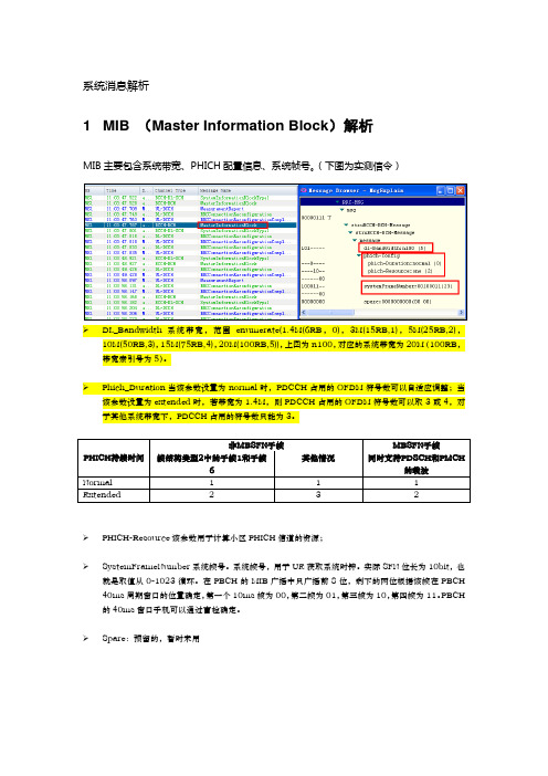
系统消息解析1 MIB (Master Information Block)解析MIB主要包含系统带宽、PHICH配置信息、系统帧号。
(下图为实测信令)➢DL_Bandwidth系统带宽,范围enumerate(1.4M(6RB,0),3M(15RB,1),5M(25RB,2),10M(50RB,3),15M(75RB,4),20M(100RB,5)),上图为n100,对应的系统带宽为20M(100RB,带宽索引号为5)。
➢Phich_Duration当该参数设置为normal时,PDCCH占用的OFDM符号数可以自适应调整;当该参数设置为extended时,若带宽为1.4M,则PDCCH占用的OFDM符号数可以取3或4,对于其他系统带宽下,PDCCH占用的符号数只能为3。
➢PHICH-Resource该参数用于计算小区PHICH信道的资源;➢SystemFrameNumber系统帧号。
系统帧号,用于UE获取系统时钟。
实际SFN位长为10bit,也就是取值从0-1023循环。
在PBCH的MIB广播中只广播前8位,剩下的两位根据该帧在PBCH 40ms周期窗口的位置确定,第一个10ms帧为00,第二帧为01,第三帧为10,第四帧为11。
PBCH 的40ms窗口手机可以通过盲检确定。
➢Spare:预留的,暂时未用2 SIB1 (System Information Block Type1)解析SIB1上主要传输评估UE能否接入小区的相关信息及其他系统消息的调度信息。
主要包括4部分:➢小区接入相关信息(cell Access Related Info)➢小区选择信息(cell Selection Info)➢调度信息(scheduling Info List)➢TDD配置信息(tdd-Config)SIB1消息解析(UE侧):RRC-MSG..msg....struBCCH-DL-SCH-Message......struBCCH-DL-SCH-Message........message..........c1............systemInformationBlockType1..............cellAccessRelatedInfo//小区接入相关信息................plmn-IdentityList//PLMN标识列表..................PLMN-IdentityInfo....................plmn-Identity ......................mcc//460 ........................MCC-MNC-Digit:0x4 (4) ........................MCC-MNC-Digit:0x6 (6) ........................MCC-MNC-Digit:0x0 (0) ......................mnc//00 ........................MCC-MNC-Digit:0x0 (0) ........................MCC-MNC-Digit:0x0 (0) ....................cellReservedForOperatorUse:notReserved (1) ................trackingAreaCode:11100(890C)//TAC跟踪区(890C)为16进制数,转换成十进制为35084,查TAC在该消息中可以查到,此条信元重要。
- 1、下载文档前请自行甄别文档内容的完整性,平台不提供额外的编辑、内容补充、找答案等附加服务。
- 2、"仅部分预览"的文档,不可在线预览部分如存在完整性等问题,可反馈申请退款(可完整预览的文档不适用该条件!)。
- 3、如文档侵犯您的权益,请联系客服反馈,我们会尽快为您处理(人工客服工作时间:9:00-18:30)。
Printed by Jouve, 75001 PARIS (FR)(19)E P 3 547 812A 1TEPZZ¥5478_ A_T(11)EP 3 547 812A1(12)EUROPEAN PATENT APPLICATION(43)Date of publication:02.10.2019Bulletin 2019/40(21)Application number: 19158125.5(22)Date of filing: 19.02.2019(51)Int Cl.:H05K 7/14(2006.01)H01L 21/50(2006.01)H01L 25/00(2006.01)H01L 23/40(2006.01)(84)Designated Contracting States:AL AT BE BG CH CY CZ DE DK EE ES FI FR GB GR HR HU IE IS IT LI LT LU LV MC MK MT NL NO PL PT RO RS SE SI SK SM TR Designated Extension States: BA MEDesignated Validation States: KH MA MD TN(30)Priority:30.03.2018KR 20180037095(71)Applicant: LSIS Co., Ltd.Gyeonggi-do 14119 (KR)(72)Inventor: JUNG, Teagsun14118 Gyeonggi-do (KR)(74)Representative: K&L Gates LLPKarolinen Karree Karlstraße 1280333 München (DE)(54)PRESSURE APPLYIN G DEVICE FOR A SWITCHIN G MODULE AN D METHOD OF ASSEMBLIN G A SWITCHING MODULE USING THE SAME(57)A method of assembling a switching modulemay arrange a first pressing member on a first supporting member, stack a plurality of switches and a plurality of cooling plates on the first pressing member along a ver-tical direction, arrange a second pressing member and a supporting member on the uppermost cooling plate,support the first supporting member and a second sup-porting member using a plurality of supporting rods, press the first pressing member using a pressing device to sep-arate between the first pressing member and the first supporting member, and insert a third pressing member between the first pressing member and the first support-ing member.EP 3 547 812A12510152025303540455055DescriptionBACKGROUND OF THE INVENTION 1. Field of the Invention[0001]The present disclosure relates to a pressing de-vice of a switching module and a method of assembling the switching module using the same.2. Description of the Conventional Art[0002]Due to the development of industry and the in-crease of the population, power demand is soaring, but power production is limited.[0003]Accordingly, a power system for supplying pow-er generated at a production site to a demand site stably without loss has become increasingly important.[0004]There is a need for FACTS (Flexible AC Trans-mission System) facilities for power flow, system voltage,and stability improvement. The FACTS facilities include reactive power compensation apparatuses such as a SVC (Static Var Compensator) or a STATCOM (STATic synchronous COMpensator). These reactive power com-pensation apparatuses are connected in parallel to a power system to compensate for reactive power required in the power system.[0005]The SVC may be configured by combining a Thyristor Controlled Reactor (TCR) that controls the phase of a reactor using a thyristor according to its ap-plication, a Thyristor Switched Capacitor (TSC) that switches a capacitor, a Fixed Capacitor Bank, and the like.[0006]The SVC may include a thyristor valve connect-ed to a transformer to control the voltage of the power system and a gate unit that controls the gate of the thy-ristor valve.[0007]When a plurality of thyristors are connected in series to each other in the thyristor valve and conducted under the control of the gate unit, a high voltage or a high current flows through the thyristor. In addition, each thy-ristor is heavy and bulky, so it is not easy to handle.[0008]Therefore, in order to construct a thyristor valve in an SVC as an assembly, many considerations such as the arrangement of the thyristor, the insulation of the thyristor, the heat dissipation of the thyristor, the weight of the thyristor, and the volume of the thyristor must be taken into account.[0009]However, an optimal SVC-related switch as-sembly has not yet been developed to satisfy all of these requirements.SUMMARY OF THE INVENTION[0010]The present disclosure is provided to solve the foregoing and other problems.[0011]Another object of the present disclosure is to provide a switch assembly of a reactive power compen-sation apparatus of a new structure.[0012]Still another object of the present disclosure is to provide a switch assembly of a reactive power com-pensation apparatus having an optimal arrangement structure satisfying various requirements.[0013]Yet still another object of the present disclosure is to provide a pressing device capable of easily raising a heavy switch and a cooling plate.[0014]Still yet another object of the present disclosure is to provide a method of assembling a switching assem-bly that can be easily assembled using a pressing device.[0015]In order to achieve the foregoing and other ob-jects, according to an aspect of the present disclosure,there is provided a method of assembling a switching module comprising a plurality of switches and a plurality of cooling plates, and first and second supporting mem-bers that support the plurality of switches and the plurality of cooling plates, and the method may include arranging a first pressing support portion on the second supporting member; stacking the plurality of switches and the plu-rality of cooling plates along a vertical direction on the first pressing support portion; arranging a first pressing member and a first supporting member on the uppermost cooling plate among the plurality of cooling plates; sup-porting the first supporting member and the second sup-porting member using a plurality of support rods; sepa-rating between the first pressing support portion and the second supporting member by pressing the first pressing support portion using a pressing device; and inserting a second pressing support portion between the first press-ing support portion and the second supporting member.[0016]Here, the pressing device may include a pres-sure supply portion formed in a pipe shape to supply pres-sure, and a pressure transmission portion formed in a solid shape and connected to the pressure supply portion to operate by the pressure.[0017]Furthermore, said separating between the first pressing support portion and the second supporting member may include inserting the pressure transmission portion through the second supporting member; allowing the pressure transmission portion to be brought into con-tact with the first pressing support portion; supplying pressure from the pressure supply portion of the pressing device to the pressure transmission portion; and pressing the first pressing support portion using the pressure from the pressure transmission portion to raise the cooling plate and the switch on the first pressing support portion.[0018]Furthermore, said allowing the pressure trans-mission portion to be brought into contact with the first pressure support portion may include inserting a protrud-ing portion formed at a front end of the pressure trans-mission portion into an insertion groove formed at a lower side of the first pressing support portion.[0019]Furthermore, the second pressing support por-tion may include a plurality of support plates having dif-ferent thicknesses, and a number of the support plates may vary according to a spacing distance between the first pressing support portion and the second supporting12。