WF2M32I-090G2UM5中文资料
Inter-M 产品中文手册
安徽省 安徽省国际会展中心 安徽省和平国际大酒店 安徽省明珠国际大酒店
三星级 五星级
陕西省 中国西部电脑城 西安中联国际家俱展览中心 西安交大附中 陕西宝鸡发电厂 陕西咸阳邮电学院
浙江省
部分样本工程
浙江饭店
浙江大酒店
杭州国际花园
世界贸易中心
五洋宾馆
五洲大酒店
香格里拉大酒店
宁波邮政大楼
瑞安市华都大酒店
其它组件
八路监听器 线路监听器 六路信号分配器 编程切换器 分区话筒 定时节目器 散热风机 直接分区器 卡 侬 公 /母 板
系统
为了适应大型复杂场所的多种要求 Inter-M设计了R-1000智能式系统 此系统具有以下功能
系统分区可分为16区 并可继续扩展 每 一区可独立控制
提供声音储存功能 可随意录制多条信息 自动定时播放
每一区对应一个火警感应器接口 当某一 区发生火警时 系统会自动在该区及上下 两区发出警报 并可由紧急呼唤器喊话 报警区域亦可手动控制
系统可对电源自动管理 发生火警时会自 动打开系统发出警报 亦可定时自动播放 交流电源切断时 能自动转入直流电系统 不影响紧急状态下的喊话和报警功能
提供二种提示钟声和报警信号
餐厅
超市
酒吧
www
网吧
咖啡厅
时装店
24
便利店
5
技术参数
输 出 功 率 (RMS): 30W 频 率 响 应 : 60Hz~20kHz 总 失 真 率 : 小 于 0.5%(at 1kHz) 电 源 : AC100V~240V, 50/60Hz 功 耗 : 80W 重 量 : PA-1000B: 4.6kg
您友好的商业伙伴
公共广播及消防报警系统 专业音响设备系列 音箱与麦克风及周边系列 CCTV监控与闭路电视系统
HMF2M32M4VGL中文资料
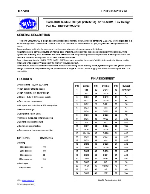
PIN ASSIGNMENTGENERAL DESCRIPTIONThe HMF2M32M4VGL is a high-speed flash read only memory (FROM) module containing 2,097,152 words organized in a x32bit configuration. The module consists of four 2M x 8bit FROM mounted on a 72-pin, single-sided, FR4-printed circuit board.Commands are written to the command register using standard microprocessor write timings.Register contents serve as input to an internal state-machine, which controls the erase and programming circuitry. Write cycles also internally latch addresses and data needed for the programming and erase operations. Reading data out of the device is similar to reading from 12.0V flash or EPROM devices.Four chip enable inputs, (/WE0, /WE1, /WE2, /WE3) are used to enable the module ’s 8 bits independently. Output enable (/OE) and write enable (/WE) can set the memory input and output.When FROM module is disable condition the module is becoming power standby mode, system designer can get low -power design. All module components may be powered from a single +3.3V DC power supply and all inputs and outputs are TTL-compatible.FEATURESPIN Symbol PIN Symbol PIN Symbol 1 Vss 25 DQ17 49 /BANKE0 2 NC 26 DQ18 50 A3 3 DQ0 27 DQ19 51 A4 4 DQ1 28 DQ20 52 A5 5 DQ2 29 DQ21 53 A6 6 DQ3 30 Vcc 54 A7 7 DQ4 31 DQ22 55 A8 8 DQ5 32 DQ23 56 A9 9 DQ6 33 /WE2 57 A10 10 Vcc 34 NC 58 A11 11 DQ7 35 DQ24 59 Vcc 12 /WE0 36 DQ25 60 A12 13 /RY_BY 37 DQ26 61 A13 14 DQ8 38 DQ27 62 A14 15 DQ9 39 Vss 63 A15 16 DQ10 40 DQ28 64 A16 17 DQ11 41 DQ29 65 A17 18 DQ12 42 DQ30 66 A18 19 DQ13 43 DQ31 67 A19 20 DQ14 44 /WE3 68 A20 21 DQ15 45 NC 69 A0 22 /WE1 46 /RESET 70 A1 23 NC 47 A2 71 NC 24DQ1648/OE72Vssw Access time : 70, 80, 90, 120ns w High-density 8MByte design w High-reliability, low-power design w Single + 3.3V ± 0.3V power supply w Easy memory expansionw All inputs and outputs are TTL-compatible w FR4-PCB design w Low profile 72-pin SIMMw Minimum 1,000,000 write/erase cycle w Sectors erase architecture w Sector group protectionw Temporary sector group unprotectionOPTIONS MARKINGw Timing70ns access -70 80ns access -80 90ns access -90 120ns access -120 w Packages72-pin SIMM MFUNCTIONAL BLOCK DIAGRAMDQ0 - DQ31A0 – A19/WE0/WE1/WE2/WE3/OE/ResetTRUTH TABLEMODE/OE /CE /WE /RESET DQ ( /BYTE=L )POWER STANDBY X H X Vcc ±0.3VHIGH-Z STANDBY NOT SELECTED H L H H HIGH-Z ACTIVE READL L H H D OUT ACTIVE WRITE or ERASE XLLHD INACTIVENOTE : X means don ’t careABSOLUTE MAXIMUM RATINGSPARAMETERSYMBOL RATING Voltage with respect to ground all other pins V IN,OUT -0.5V to Vcc+0.5V Voltage with respect to ground Vcc V CC -0.5V to +4.0VStorage TemperatureT STG-65o C to +150o COperating Temperature T A -55o C to +125o CThis is a stress rating only and functional operation of the device at these or any other conditions above those indicated in the operating section of this specification is not implied. Exposure to absolute maximum rating conditions for extended periods may affect reliability.RECOMMENDED DC OPERATING CONDITIONSPARAMETERSYMBOL MIN TYP. MAX Vcc for ± 10% device Supply Voltages Vcc 2.7V 3.6V Ground V SSDC AND OPERATING CHARACTERISTICS ( 0o C ≤ T A ≤ 70 o C )PARAMETERTEST CONDITIONSSYMBOL MIN TYP MAX UNI T Input Load Current Vcc=Vcc max, V IN = Vss to Vcc I L1 ±1.0 µA A9 Input Loda Current Vcc=Vcc max, ; A9=12.5 V I L1T 35 µA Output Leakage CurrentVcc=Vcc max, V OUT = Vss to Vcc I L0±1.0 µA5MHz 9 16 /CE= V IL, /OE= V IH, Byte Mode1MHz 2 4 5MHz 9 16 Vcc Active Read Current (1)/CE= V IL, /OE= V IH, Word Mode1MHzI CC1 2 4 µA Vcc Active Write Current (Note2,3,4)/CE = V IL , /OE=V IH I CC2 20 30 mA Vcc Standby Current(Note2)/CE, /RESET=Vcc ±0.3VI CC30.25mAVcc Standby Current DuringReset(Note2)/RESET=Vss±0.3V I CC40.2 5 mAAutomatic Sleep Mode(Note2,5) V IH= Vcc ±0.3V;V IL= Vss ±0.3V;V CC50.2 5 VInput Low Voltage V IL-0.5 0.8 VInput High Voltage V IH 0.7×VccVcc+0.3VVoltage for Autoselect andTemporary Sector UnprotectV CC = 3.3V V ID11.5 12.5 V Output Low Voltage I OL = 4.0mA, Vcc =Vcc min V OL0.45 VI OH = -2.0mA, Vcc =Vcc min 0.85×VccVOutput High VoltageI OH = -100µA, Vcc =Vcc min Vcc-0.4Low Vcc Lock-Out Voltage(Note4)V LKO 2.3 2.5 V Notes1. The Icc Current listed is typically less than 2 ma/MHz,with /OE at V IH. Typical Vcc is 3.0V.2. Maximum Icc Specifications are tested with Vcc=Vccmax.3. Icc active while Embedded Erase of Embedded Program is in progress.ERASE AND PROGRAMMING PERFORMANCELIMITSPARAMETERMIN. TYP. MAX.UNIT COMMENTSSector Erase Time - 0.7 15 sec Chip Erase Time 25 sec Excludes 00H programming prior to erasureByte Programming Time - 9 300 µs Chip Programming Time - 18 54 sec Excludes system-level overheadTSOP CAPACITANCEPARAMETER SYMBOLPARAMETERDESCRIPTION TEST SETUP MIN MAX UNITC IN Input Capacitance V IN = 0 6 7.5 pFC OUT Output Capacitance V OUT = 0 8.5 12 pFC IN2 Control Pin Capacitance V IN = 0 7.5 9 pF Notes : Test conditions T A = 25o C, f=1.0 MHz.AC CHARACTERISTICSu Read Only Operations CharacteristicsPARAMETER SYMBOLS Speed OptionsJEDEC STANDARD DESCRIPTIONTEST SETUP-70R -80 -90 -120 UNITt AVAV t RC Read Cycle Time (Note 1)Min 70 80 90 120 ns t AVQV t ACC Address to Output Delay /CE = V IL /OE = V IL Max 70 80 90 120 ns t ELQV t CE Chip Enable to Output Delay /OE = V IL Max 70 80 90 120ns t GLQV t OE Chip Enable to Output Delay Max 30 30 35 35 ns t EHQZ t DF Chip Enable to Output High-Z Max 25 25 30 30 ns t GHQZ t DF Output Enable to Output High-ZMax 25253030ns Read Min 0Output Enable Hold Time(Note 1)Toggle and /Data PollingMin 10 nst AXQX t QH Output Hold Time From Addresses, /CE or /OE, Whichever Occurs FirstMinnsNotes :1. Not 100% tested.2. See Figure 5 and Table 10 for test specifications.TEST SPECIFICATIONSTEST CONDITION70R, 8090, 120UNIT Output load1TTL gateOutput load capacitance,C L (Including jig capacitance) 30100 pF Input rise and fall times 5 ns Input pulse levels0.0-3.0 V Input timing measurement reference levels 1.5 V Output timing measurement reference levels 1.5V2.7k ΩDiodes = IN3064 or EquivalentNote LPARAMETER SYMBOLSSpeed Options JEDEC STANDARDDESCRIPTION70R 80 90 120 UNITt AVAV t WC Write Cycle Time Min 708090120ns t AVWL t AS Address Setup Time Min 0ns t WLAX t AH Address Hold Time Min 45 45 45 50 ns t DVWH t DS Data Setup Time Min 35354550ns t WHDX t DH Data Hold TimeMin 0 ns t OES Output Enable Setup Time Min 0 ns t GHWL t GHWL Read Recover Time Before Write Min 0 ns t ELWL t CS /CE Setup Time Min 0 ns t WHEH t CH /CE Hold Time Min 0ns t WLWH t WP Write Pulse Width Min 35353550ns t WHWL t WPH Write Pulse Width High Min 30 ns Byte Typ 9 t WHWH1 t WHWH1 Byte Programming OperationWordTyp 11 µs t WHWH2 t WHWH2 Sector Erase Operation (Note1) Typ 0.7 sec t VCS Vcc set up timeMin 50 µs t RB Recovery Time from RY//BY Min 0 ns t BUSYProgram/Erase Valid to RY//BY DelayMin90ns Notes :1. Not 100% tested.2. See the “Erase and Programming Performance ” section for more information.Alternate /CE Controlled WritesPARAMETER SYMBOLS Speed Options JEDEC STANDARDDESCRIPTION-70R -80 -90 120 UNITt AVAV t WC Write Cycle Time Min 708090120ns t AVWL t AS Address Setup Time Min 0ns t WLAX t AH Address Hold Time Min 45 45 45 50 ns t DVEH t DS Data Setup Time Min 35354550ns t EHDX t DH Data Hold TimeMin 0 ns t OES Output Enable Setup Time Min 0 ns t GHEL t GHEL Read Recover Time Before Write Min 0 ns t WLEL t WS /WE Setup Time Min 0 ns t EHEH t WH /WE Hold Time Min 0ns t ELEH t CP /CE Pulse Width Min 35353550ns T EHEL t CPH /CE Pulse Width High Min 30 ns Byte Typ 9 t WHWH1t WHWH1Byte Programming OperationWordTyp 11 µs t WHWH2 t WHWH2Sector Erase OperationTyp0.7secNotes :1. Not 100% tested.2. See the “Erase and Programming Performance ”section for more information.u READ OPERATIONS TIMINGu RESET TIMINGu PROGRAM OPERATIONS TIMINGu CHIP/SECTOR ERASE OPERATION TIMINGSu DATA# POLLING TIMES(DURING EMBEDDED ALGORITHMS) u TOGGLE# BIT TIMINGS (DURING EMBEDDED ALGORITHMS)u SECTOR PROTECT UNPROTECT TIMEING DIAGRAMu ALTERNATE CE# CONTROLLED WRITE OPERATING TIMINGSPACKAGE DIMENSIONSORDERING INFORMATIONPart NumberDensityOrg.PackageComponent Number VccSPEEDHMF2M32M4VGL-70 8MByte 2Mx 32Bit 72Pin -SIMM 4EA 3.3V70ns HMF2M32M4VGL-80 8MByte 2Mx 32Bit 72Pin -SIMM 4EA 3.3V 80ns HMF2M32M4VGL-90 8MByte 2Mx 32Bit 72Pin -SIMM 4EA 3.3V 90ns HMF2M32M4VGL-120 8MByte2Mx 32Bit72Pin -SIMM4EA3.3V120ns(Solder & Gold Plating)。
无线路由器

无线路由器TL-TR960G•ax3000双频千兆wi-fi 6 无线路由器TL-XDR3050易展版•ax3000双频wi-fi 6无线路由器TL-XDR3068易展Turbo版•ax11000三频super wi-fi 6e无线路由器(双10g口)TL-XTR10890易展Turbo版•ax5400双频千兆wi-fi 6 无线路由器TL-XDR5450易展Turbo版•ax3000双频wi-fi 6无线路由器(2.5g口)TL-XDR3066易展Turbo版•ax5400三频wi-fi 6无线路由器(2.5g口)TL-XTR5466易展Turbo版•ax1800双频千兆wi-fi 6无线路由器TL-XDR1860易展版玉白•ax3000双频wi-fi 6无线路由器(2.5g口)TL-XDR3040易展版•ax10200三频super wi-fi 6无线路由器(2.5g口)TL-XTR10280易展Turbo版•ax7800三频super wi-fi 6无线路由器(2.5g口)TL-XTR7880易展Turbo版•ax5400双频 wi-fi 6 无线路由器(2.5g口) TL-XDR5470易展Turbo版•ax6000双频 wi-fi 6 无线路由器(2.5g口) TL-XDR6070易展Turbo版•ax5400三频wi-fi 6无线路由器(2.5g口)TL-XTR5460易展Turbo版•ax3000双频千兆wi-fi 6无线路由器TL-XDR3010易展版•ax6000双频super wi-fi 6 无线路由器(2.5g口) TL-XDR6080易展Turbo版•ax5400双频super wi-fi 6 无线路由器(2.5g口) TL-XDR5480易展Turbo版•ax3000双频wi-fi 6无线路由器(2.5g口)TL-XDR3060易展Turbo版•ax11000三频光纤wi-fi 6 无线路由器(2.5g网口)TL-XTR11060 易展 Turbo版•ax3200双频千兆wi-fi 6 无线路由器TL-XDR3250易展版•ax3200双频千兆wi-fi 6 无线路由器TL-XDR3230易展版•ax5400双频千兆wi-fi 6 无线路由器TL-XDR5430易展版•ax6000双频千兆wi-fi 6 无线路由器TL-XDR6030易展版•ax1800双频千兆wi-fi 6无线路由器套装TL-XDR1850易展版套装•ax1800双频千兆wi-fi 6无线路由器TL-XDR1850易展版•ac1200双频千兆无线路由器TL-WDR5650千兆易展版•ac1900双频千兆无线路由器TL-WDR7660千兆易展Turbo版•ax1800双频千兆wi-fi 6无线路由器TL-XDR1860易展版•ac1200双频千兆无线路由器TL-WDR5620千兆易展版千兆有线网口搭配4根外置天线,性能强劲无阻;双频同时工作,2.4GHz频段速度300Mbps,5GHz频段速度867Mbps!•ac1200双频千兆无线路由器TL-WDR5660千兆易展版千兆有线网口搭配4根外置天线,性能强劲无阻;双频同时工作,2.4GHz频段速度300Mbps,5GHz频段速度867Mbps!•ax6000双频光纤wi-fi 6 无线路由器(2.5g网口)TL-XDR6060 易展 Turbo版•ac2600双频千兆无线路由器TL-WDR8690易展版•ac1900双频千兆无线路由器TL-WDR7632千兆易展版•ac1900双频千兆无线路由器TL-WDR7661千兆易展版•ac2600双频千兆无线路由器TL-WDR8661易展版•ac2600双频千兆无线路由器TL-WDR8670易展版套装•ac2600双频千兆无线路由器TL-WDR8670易展版•ac1200双频无线路由器TL-WDR5650易展版•ac1200双频无线路由器TL-WDR5650易展版套装•ac1900双频千兆无线路由器TL-WDR7651千兆易展版•ac1200双频无线路由器TL-WDR5620易展版•ac1900双频千兆无线路由器TL-WDR7690千兆易展Turbo版•ac1900双频千兆无线路由器TL-WDR7680千兆易展Turbo版•ac1900双频千兆无线路由器TL-WDR7650千兆易展Turbo版•ac1900双频千兆无线路由器TL-WDR7620千兆易展版•ac1900双频千兆无线路由器TL-WDR7660千兆易展版•ac1900双频无线路由器TL-WDR7620•ac2600双频千兆无线路由器TL-WDR8690深海蓝•ac1900双频千兆无线路由器TL-WDR7650千兆易展版套装•ac1900双频千兆无线路由器TL-WDR7650千兆易展版•ac2600双频千兆无线路由器TL-WDR8690。
W02-无线产品系列

802.11a/b/g/n 物联网AP WNDAP660 WNDAP380R
802.11a/b/g/n WNDAP620 WNDAP660
WNDAP360
WNAP320
ANT24D18 天馈线
NETGEAR 集中控制型无线控制器产品线
Cloud-WC
WC9800
Cloud-WMS Features
支持802.11a/b/g/n 最大支持500个AP/单台 3台最大支持1500个AP RF,Channel自动调整
支持所有NETGEAR 企业级11N AP AP自动搜索和发现 支持Web Portal, 802.1x, Guest 认证等 支持Radius,LDAP认证 负载均衡,快速漫游
DHCP Server
保修
1年
WC7510L
无
NETGEAR WMS5316无线管理系统
固定机箱 千兆RJ45端口 电源接口(220V) 最大管理16个AP
采购型号
WMS5316
模块描述
16 AP智能无线管理系统-4个10/100/1000Base-T 端口;支持16个AP管理;支持IEEE802.11a/b/g/n协 议;可管理WNDAP350,WNAP210, WG302v2, WG103, WN802Tv2, WG602v4
WLAN“热图”
终端定位
全面安全你的企业网络
认证: Web Portal, 802.1x,WebAAA,MAC,OPEN 加密: WEP/WPA-P/WPA2-P/WPA-E/WPA2-E/802.1x Radius/AAA; 协议: Radius, AD域, LDAP 安全Байду номын сангаас 每SSID可设置独立Radius AAA; Radius Accounting Protocol Guest Access: 内置Portal,密码本地认证和存储,客户邮箱地址自动注册 Rogue AP: 可检测和映射多达512个非法AP;Rogue AP包括非法AP,干扰AP等 记录:详细认证用户及设备详细活动记录
昭阳产品信息
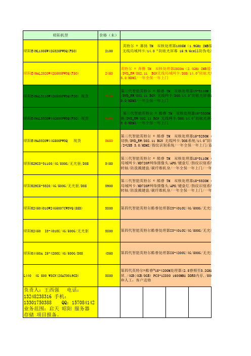
3500
第三代智能英特尔 ® 酷睿 TM 双核处理器i5-3320M (2.6GHz) ,3MB智能高速 换/DVD_RW/802.11 BGN 无线网卡/DOS/14.0"防眩光屏幕16:9/30万像素网络摄 /2*USB 3.0/HDMI/一年全保一年上门
昭阳E49A3320W44G500PW3Q
昭阳机型
价格(未)
具
体
配
昭阳E49L1005W42G320PW3Q(FSO)
2100
英特尔 ® 赛扬 TM 双核处理器1005M(1.9GHz 2MB缓存) /2GB DDR3 160 BGN 无线局域网卡/14.0“防眩光屏幕 16:9/6cell防伪电池/30万像素摄像头/ 一年上门
昭阳E49AL2020W42G500PW3Q(FSO)
3900
第三代智能英特尔 ® 酷睿 TM 双核处理器i5-3320M (2.6GHz)/1*4GB DDR3 1 局域网卡/HD720P网络摄像头/APS/键盘灯/指纹识别系统/蓝牙4.0模块/USB3.0 金转轴/防泼溅键盘/碳纤维机身/一年全保一年上门/一年意外保护
昭阳K24504010W24G5007CW3VQ(SSD)
理器i5-3320M (2.6GHz) ,3MB智能高速缓存/4GB DDR3 1600/500GB/Nvidia 610M 1G独立显卡 支持双显卡切 4.0"防眩光屏幕16:9/30万像素网络摄像头/6cell防伪电池/180度高强度合金转轴/排水型防泼溅键盘
理器i5-3230M (2.6GHz) ,3MB智能高速缓存/4GB DDR3 1600MHz/500GB/Nvidia 610M 1G独立显卡 支持双显卡 系统/14.0"防眩光屏幕16:9/HD 720P网络摄像头/6cell防伪电池/180度高强度合金转轴/排水型防泼溅键盘 保一年上门/蓝牙
GIGABYTE M32U M32Q 用户手册说明书
USER GUIDECopyright© 2022 GIGA-BYTE TECHNOLOGY CO., LTD. All rights reserved.The trademarks mentioned in this manual are legally registered to their respective owners.DisclaimerInformation in this manual is protected by copyright laws and is the property of GIGABYTE.Changes to the specifications and features in this manual may be made by GIGABYTE without prior notice.No part of this manual may be reproduced, copied, translated, transmitted,or published in any form or by any means without GIGABYTE’s prior written permission.• In order to assist in the use of this monitor, carefully read the U ser Guide.• For more information, check on our website at:https://The terms HDMI and HDMI High-Definition MultimediaInterface, and the HDMI Logo are trademarks or registeredtrademarks of HDMI Licensing Administrator, Inc. in the UnitedStates and other countries.Safety PrecautionsRead through the following Safety Precautions before using the monitor.• Only use the accessories that are provided with the monitor or that which are recommended by the manufacturer.• Keep the plastic packaging bag for the product in a place that cannot be reached by children.• Before connecting the monitor to the power outlet, make sure that the voltage rating of the power cable is compatible with the power specification in the country where you are located.• The power cord plug must be connected to a properly wired and grounded power outlet.• Do not touch the plug with wet hands, otherwise easily cause electric shock.• Place the monitor in a stable and well-ventilated place.• Do not place the monitor near any heat sources such as electric radiators or direct sunlight.• The holes or openings on the monitor are for ventilation. Do not cover or block the ventilation holes with any objects.• Do not use the monitor near water, drinks, or all types of liquids. Failure to do so may result in electric shock or damage to the monitor.• Make sure to unplug the monitor from the power outlet before cleaning.• As the screen surface is easy to be scratched, avoid touching the surface with any hard or sharp object.• Use a soft lint-free cloth instead of a tissue to wipe the screen. You may use a glass cleaner to clean the monitor if required. However, never spray the cleaner directly onto the screen.• Disconnect the power cable if the monitor is not being used for a long period of time.• Do not attempt to disassemble or repair the monitor yourself.Stability Hazard PrecautionsThe product may fall, causing serious personal injury or death. To prevent injury, this product must be securely attached to the floor/wall in accordance with the installa-tion instructions.Many injuries, particularly to children, can be avoided by taking simple precautions such as:• ALWAYS use stands or installation methods recommended by the manufacturer of the product set.• ALWAYS use furniture that can safely support the product.• ALWAYS ensure the product is not overhanging the edge of the supporting furniture.• ALWAYS educate children about the dangers of climbing on furniture to reach the product or its controls.• ALWAYS route cords and cables connected to your product so they cannot be tripped over, pulled or grabbed.• NEVER place the product on tall furniture (for example, cupboards or bookcases) without anchoring both the furniture and the product to asuitable support.• NEVER place the product on cloth or other materials that may be located between the product and supporting furniture.• NEVER place items that might tempt children to climb, such as toys and remote controls, on the top of the product or furniture on which the product is placed.• If the existing product is going to be retained and relocated, the same considerations as above should be applied.• To prevent personal injury or damage to the product caused by tipping over due to earthquakes or other shocks, make sure to install the product in astable location and take measures to prevent falling.User Comfort RecommendationsThe following are some tips for comfortable viewing of your monitor:• Optimal viewing distances for monitors range from approximately 510 mm to 760 mm (20 in to 30 in).• A general guideline is to position the monitor such that the top of the screen is at or slightly below your eye-height when you are comfortably seated.• Use adequate lighting for the type of work you are performing.• Take regular and frequent breaks (at least for 10 minutes) every 30 minutes.• Be sure to periodically look away from your monitor screen and focus on a far object for at least 20 seconds during the breaks• Eye exercise can help reduce eye strain. Repeat these exercises frequently: (1) look up and down (2) slowly roll your eye (3) move your eyes diagonally.ContentINTRODUCTION (5)Unpacking (5)Package Contents (7)Product Overview (8)GETTING STARTED (10)Installing the Stand Base (10)Lift the monitor (15)Adjusting the Viewing Angle (16)Pivot mode (20)Instructions for thread trimmer ring (22)Installing a Wall-Mount Bracket (Optional) (23)Making Connections (25)USING THE DEVICE (26)Turning the Power On/Off (26)User Comfort Recommendations (27)OPERATIONS (29)Quick Menu (29)Configure the Device Settings (36)APPENDICES (47)Specifications (47)Supported Timing List (48)Troubleshooting (49)Basic Care (50)Notes on USB Charging (50)GIGABYTE Service Information (50)SAFETY INFORMATION (51)Regulatory Notices (51)INTRODUCTIONUnpacking1. Open the upper cover of the packaging box. Then observe the unpackinginstruction attached on the inner cover. Making sure the box is in thecorrect orientation, carefully lay the box on the stable surface pen.2. Remove the items from the upper EPS foam.3. Remove the upper EPS foam. T hen you can remove the stand from the lower EPSfoam.Package ContentsThe following items come with your packaging box. If any of them is missing, please contact your local dealer.Monitor ClampPower Cable HDMI CableUSB CableArmDP CableW a r r a n ty Ca r dQuick Start GuideWarranty CardNote: Please keep the packaging box and packing materials for future transporta-tion of the monitor.Product OverviewFront View1 Control buttonRear View1 AC IN jack2AC power switch3Kengsington lock4HDMI ports (x2)5DisplayPort6Type-C port7 USB upstream port8 USB 3.0 ports (x3)9 Headphone jackGETTING STARTEDInstalling the Stand Base1. Align the monitor base with the standoff underneath the stand. Then lift thescrew ring and turn it clockwise to secure the monitor base in place.2.Note: We recommend that you cover the table surface with soft cloth to prevent damage to the monitor.4. Align and slide the hooks of the stand into the mounting slots on the rear of thescreen.5. Please make sure the knob is clamped in place.CAUTION!The C-clamp accessory is designed to be used with this monitor only. Usingthis accessory with any other product may result in damage and/or injury.Make sure the mounting surface is flat and strong enough to handle the monitor. Do not install on glass surfaces.Improper installation may cause property damage and/or personal injury.1. When adjusting the screen position, hold the left and right sides of the screen toavoid damaging the screen by pressing the front side of the screen.2. When adjusting the Monitor, please hold the Monitor border.Do not press the front of the Monitor to avoid damage caused by pressing the screen.3. When moving the Monitor, hold the border of the Monitor to avoid pressing thefront of the Monitor or damaging the screen.4. Make sure there is adequate ventilation when placing the product. A rise ininternal temperature may cause flame and damage the product.Lift the monitorCarefully lift the monitor, turn it over and place it upright on its stand on a flat even surface.Remove the foam wrap from the monitor.Note: Consider keeping the box and packaging in storage for use in the future when you may need to transport the monitor. The fitted foam packing is ideal for protecting the monitor during transport.Adjusting the Viewing AngleNote: Hold the monitor base so that the screen does not topple when you make the adjustment.Adjusting the Tilt AngleTilt the screen forward or backward to the desired viewing angle (-5˚ to 25˚).Tilt the Stand forward or backward to the desired viewing angle (23.7˚ to 83.7˚).Adjusting the Swivel AngleSwivel the screen to the left or right for the desired viewing angle (±100˚).Swivel the Stand to the left or right for the desired viewing angle (±170˚).Changing the Screen OrientationRaise the screen to the highest position (50mm).Note: Before making the height adjustment, make sure you have removed the safety plate from the stand.R otate the monitor (90˚ clockwise) to portrait orientation.When adjusting the bracket, pay attention to the objects under the Monitor.When adjusting the support, do not move the Monitor away from the desktop to avoid security problems.Pivot modeWhen using Pivot mode, do not directly spin fast, but switch mode as follows.Pivot mode Conversion step1. Raise Monitor to the highest point.2. Adjust the Monitor tilt Angle to the highest point (as shown).3. Rotate Monitor clockwise (as shown in figure).4. After 90 degrees rotation,Complete the Pivot mode (as shown).A B3. Attach the mounting bracket to the mounting holes at the rear of the monitor.Then use the screws to secure the bracket in place.Note: To mount the monitor on the wall, refer to the installation guide that is included in the wall-mount bracket kit. VESA Mounting Screw M4 x 8mm minimum.Making Connections1 Power cable2HDMI cable3DisplayPort cable4Type-C cable5USB (A-Male to B-Male) cable 6USB cable7 Headphone cableUSING THE DEVICETurning the Power On/OffMake sure the power switch next to the AC power input jack is switched to ON. Power On1. Connect one end of the power cable to the AC IN jack at the rear of the monitor.2. Connect other end of the the power cable to a power outlet.3. Press the Control button to turn on the monitor. The Power LED will light inwhite, indicating the monitor is ready to use.Power OffPress the Control button for 2 seconds to turn off the monitor.Note: When the Main menu appears on the screen, you can also turn off the monitor by moving the Control button down (). Refer to page 31User Comfort RecommendationsThe Monitor adopts Flicker-Free technology which clears the eye visible monitor flicker and prevents users from suffering eye strain and fatigue.The following are some tips for comfortable viewing of your monitor:• Optimal viewing distances for monitors range from approximately 510 mm to 760 mm (20” to 30”).• A general guideline is to position the monitor such that the top of the screen is at or slightly below your eye-height when you are comfortably seated.• Use adequate lighting for the type of work you are performing.• Take regular and frequent breaks (at least for 10 minutes) every half- hour.• Be sure to periodically look away from your monitor screen and focus on a far object for at least 20 seconds during the breaks.• Eye exercise can help reduce eye strain. Repeat these exercises frequently: (1) look up and down (2) slowly roll your eye (3) move your eyes diagonally.Selecting the Input Source1. 2.Move the Control button right() to enter the Input menu.Select ExitHDMI 1HDMI 2Move the Control button center() to select the desiredinput source. Then press theControlType-COPERATIONS Quick MenuHot KeyBy default, the Control button has been assigned with the specific function.Note: To change the preset hot key function, refer to the “Quick Switch” section on page 43.To access the hot key function, do the following:• Move the Control button up () to enter the Black Equalizer menu.Move the Control button up/down () to adjust the setting and press the Control • Move the Control button down () to enter the Picture Modemenu.Move the Control button center () to select the desired option and press the ControlSelect ExitFPS RTS/RPG Movie Reader sRGB• Move the Control button left () to enter the Volume m enu.Move the Control button up/down () to adjust the headphonevolume level and press the Control• Move the Control button right () to enter the the Input menu. Refer to the “Selecting the Input Source” section.Note: To close the menu, move the Control button left ().Function Key Guide• Press the Control button to display the Main menu.KVM (Multi Task)Then use the Control button to select the desired function and configure the related settings.KVMWhen the Main menu appears on the screen, move the Control button left () to enter the KVM menu.SelectExitKVMKVM WizardKVM ONKVM Reset• KVM Switch: Switch the input source that has been assigned to USB-B or Type-C connection in the KVM Wizard settings.When there are several input signals connected to the device, a message box will appear on the screen once the system detected USB Type-C input signal.To switch to USB Type-C input source, simply press the KVM button or the Control button.However, when there is no input signal from currently selected input source, the system will return to the previous connected input source.Note: This option will be disabled if the KVM button function is disabled (KVM OFF).• KVM Wizard: Configure the KVM related settings.Set the input source to be bound with USB Type-B connection first, andthen following with USB Type-C connection.HDMI2DisplayPortType-CSelect Enter Select TYPE-C DisplayHDMI 1HDMI2DisplayPortType-CSelect EnterUSB-B Display Selection TYPE-C Display Selection Note: If you set the USB-B Display setting to Type-C, the TYPE-C Display menuoption will automatically be disabled. You will then see the KVM status in the KVM Wizard page as below.KVM StatusUSB-B : Type-CType-C : N/A• KVM ON/OFF: Enable/Disable the KVM button function.√ Select ON to enable the KVM button function. Once the systemdetected USB Type-C input signal, a message box will appear on thescreen.Press the KVM button or the Control button to switch to USB Type-C input source.Note: When the KVM button function is enabled, the KVM ON will be displayed on the left panel.√ Select OFF to disable the KVM button function.Note: When the KVM button function is disabled, the KVM OFF will be displayed on the left panel.• KVM Reset: Restore the KVM default settings.√ HDMI 1 input source is bound with USB Type-B connection.√ USB Type-C input source is bound with USB Type-C connection. √ The KVM ON/OFF function is set to ON .Game Assist• When the Main menu appears on the screen, move the Control button right () to enter the Game Assist menu.Select ExitGameAssistDisplay AlignmentCrosshair Dashboard Gaming Timer Gaming Counter Refresh Rate Info LocationOFF Count Up Count Down• Game INFO : Configure the FPS (First Person Shooting) g ame related settings.√ Select Gaming Timer to select countdown timer mode. To disable this function, set the setting to OFF .√ Select Gaming Counter or Refresh Rate to enable/disable the gaming counter or real-time refresh rate setting.√ Select Info Location to specify the location of the information to beshown on the screen.6000:00001440045• Crosshair : Select the desired crosshair type to suit your gamingenvironment. It makes aiming much easier.• Dashboard : Configure the dashboard settings.√ ON : Enable the function. Then select the desired option(s) to be shownon the screen.√ OFF: Disable the function.√ Dashboard Location: Specify the location of the Dashboard information to be shown on the screen. Once the Dashboard configuration iscomplete, it will transfer the system data to the SOC through the USBport and display the value of the selected function(s) on the screen.Note: Make sure the USB cable is properly connected to the USB upstream port of the monitor and the USB port of your computer.• Display Alignment: When the function is enabled, it displays the alignment lines on the four sides of the screen, providing handy tool for you to line up multiple monitors perfectly.Configure the Device SettingsWhen the Main menu appears on the screen, move the Control button up () to enter the Settings menu.Note: Use the Control button to navigate through the menu and make adjustments.Button GuideGamingConfigure the game related settings.PictureConfigure the image related settings.Note: The Monitor use low blue light panel and compliance with TÜV Rheinland Low Blue Light Hardware Solution at factory reset/default setting mode (Brightness: 70, Contrast: 50, CCT: 6500, Preset mode: Standard mode).Note: The HDR Enhance function will appear after HDR turns on. And the Picture Mode list will be replaced until the HDR turns off.DisplayConfigure the display screen related settings.Configure the multi-picture related settings.Configure the system related settings.LanguageSave Settings Save all data.Reset AllRestore the monitor to its factory default settings.APPENDICESSpecificationsSupported Timing ListTroubleshooting。
霍尼韦尔无线条码扫描枪
霍尼韦尔无线条码扫描枪文章来源:扫描网霍尼韦尔无线条码扫描枪都有哪些?我们知道霍尼韦尔是条码设备的尖端制造商,Honeywell旗下产品包括坚固耐用的移动数据终端以及Honeywell扫描枪,致力于为零售、运输、分销、仓储和制造业等行业客户量身定制独特的产品。
霍尼韦尔扫描设备有霍尼韦尔手持式条码扫描枪、霍尼韦尔二维条码扫描器、霍尼韦尔无线条码扫描枪、霍尼韦尔扫描平台、霍尼韦尔工业扫描枪这几大类。
那么霍尼韦尔无线条码扫描枪都有哪些呢?下面我们将霍尼韦尔无线条码扫描枪的型号都整理出来,希望对于正在挑选无线条码扫描枪的您有所帮助。
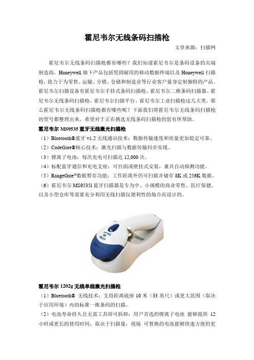
霍尼韦尔MS9535蓝牙无线激光扫描枪(1)Bluetooth®蓝牙v1.2无线通讯技术:数据传输速度和质量更加稳定可靠。
(2)CodeGate®核心技术:激光扫描与数据传输同步实现。
(3)锂离子电池:每次充电可扫描近12,000次。
(4)标配蓝牙通信和充电支座:可台面或壁挂式安装,兼具自动探测功能。
(5)RangeGate™数据暂存功能:工作距离外仍可扫描并储存8K或256K数据。
(6)霍尼韦尔MS9535l蓝牙扫描器是专为中、小规模的商业零售、医疗保健、以及小型仓库等需要充分利用无线扫描仪便利性的场合而设计的。
霍尼韦尔1202g无线单线激光扫描枪(1)Bluetooth® 无线技术:支持距离底座10米(33英尺)或更大范围(取决于应用环境)内的标准一维条码的扫描。
(2)电池寿命持久且无需工具即可拆卸:用户首选的锂离子电池能够提供12小时或更长的使用时间,取决于扫描量;现场可替换的电池能够快速方便的更换,而无需使用任何工具。
自动接口配置:单一设备支持所有常用接口,通过自动接口检测和配置取代了耗时费力的编程条码扫描过程。
(3)卓特越的低质量条码识读性能:快速扫描各种一维条码,包括那些破损的和脏污的条码,增加了一次扫描通过率并减少了手动键盘输入带来的错误。
H3C无线WLAN产品介绍

H3C无线WLAN产品介绍目录1.H3C无线网络产品介绍 (2)1.1H3C WA1208E-GP室内合路型大功率无线接入设备 (2)1.2H3C WA2612-AGN室内型单频802.11N无线接入设备 (6)1.3H3C WA2610E-GNP室内合路型大功率802.11N 无线接入设备 (10)1.4H3C WX6100E系列多业务无线控制器 (14)1.4.1 产品简介 (14)1.4.2 产品特点 (17)1.4.3 产品规格 (21)1.5H3C S3100-EI系列安全易用交换机产品彩页 (27)1.5.1 产品概述 (27)1.5.2产品特点 (28)1.5.3产品规格 (30)1.5.4组网应用 (35)1.6H3C S5120-SI系列全千兆安全智能交换机 (37)1.6.1 产品概述 (37)1.6.2 产品特点 (37)1.6.3 产品规格 (38)1.6.4 组网应用 (40)1.7H3C S5500-EI系列增强型IP V6万兆交换机 (41)1.7.1 产品概述 (41)1.7.2 产品特点 (42)1.7.3 产品规格 (43)1.7.4 组网应用 (46)1.8H3C智能管理中心平台组件宣传彩页 (48)1.8.1 产品简介 (48)1.8.2 产品特点 (48)1.8.3 运行环境 (55)1.8.4 组网应用 (55)1.9 I MC WSM无线运营管理组件产品彩页 (55)1.9.1 产品简介 (55)1.9.2 产品特点 (56)1.9.3 运行环境 (59)2.其他要求 (60)2.1H3C公司总体描述 (60)2.2H3C WLAN产品现状研究 (60)2.3H3C WLAN产品应用 (61)2.4用户使用报告 (65)2.5工程经验 (65)1.H3C无线网络产品介绍1.1 H3C WA1208E-GP室内合路型大功率无线接入设备WA1208E-GP室内合路型大功率无线接入设备产品概述H3C WA1208E-GP是杭州华三通信技术有限公司(H3C)自主研发的室内合路型大功率无线接入设备(以下简称AP),最大发射功率可达500mW。
- 1、下载文档前请自行甄别文档内容的完整性,平台不提供额外的编辑、内容补充、找答案等附加服务。
- 2、"仅部分预览"的文档,不可在线预览部分如存在完整性等问题,可反馈申请退款(可完整预览的文档不适用该条件!)。
- 3、如文档侵犯您的权益,请联系客服反馈,我们会尽快为您处理(人工客服工作时间:9:00-18:30)。
White Electronic DesignsWF2M32-XXX5FIGURE 1 – PIN CONFIGURATION FOR WF2M32-XHX52Mx32 5V Flash ModuleOrganized as 2Mx32Commercial, Industrial, and Military Temperature Ranges5 Volt Read and Write. 5V ± 10% Supply.Low Power CMOSData# Polling and Toggle Bit feature for detection of program or erase cycle completion.Supports reading or programming data to a sector not being erased.RESET# pin resets internal state machine to the read mode.Built in Decoupling Caps and Multiple Ground Pins for Low Noise Operation, Separate Power and Ground Planes to improve noise immunity* T his product is subject to change without notice.Note: For programming information refer to Flash Programming 16M5 Application Note.FEATURESAccess Time of 90, 120, 150nsPackaging:• 66 pin, PGA Type, 1.185" square, Hermetic Ceramic HIP (Package 401).• 68 lead, Hermetic CQFP (G2U), 22.4mm (0.880") square (Package 510) 3.56mm (0.140") height. Designed to fi t JEDEC 68 lead 0.990" CQFJ footprint (FIGURE 3)Sector Architecture• 32 equal size sectors of 64KBytes per each 2Mx8chip • Any combination of sectors can be erased. Also supports full chip erase.Minimum 100,000 Write/Erase Cycles MinimumWhite Electronic Designs WF2M32-XXX5 FIGURE 2 – PIN CONFIGURATION FOR WF2M32-XG2UX5White Electronic Designs WF2M32-XXX5ABSOLUTE MAXIMUM RATINGS Parameter Symbol Ratings Unit Voltage on Any Pin Relative to V SS V T-2.0 to +7.0V Power Dissipation P T8W Storage Temperature T stg-65 to +125°C Short Circuit Output Current I OS100mA Endurance – Write/Erase Cycles(Extended Temp)100,000 min cycles Data Retention20yearsRECOMMENDED DC OPERATING CONDITIONS Parameter Symbol Min Typ Max Unit Supply Voltage V CC 4.5 5.0 5.5V Ground V SS000V Input High Voltage V IH 2.0-V CC + 0.5V Input Low Voltage V IL-0.5-+0.8V Operating Temperature (Mil.)T A-55-+125°C Operating Temperature (Ind.)T A-40-+85°CNOTES:1. The I CC current listed includes both the DC operating current and the frequencydependent component (@ 5MHz). The frequency component typically is less than 2mA/MHz, with OE# at V IH.2. I CC active while Embedded Algorithm (program or erase) is in progress.3. DC test conditions V IL = 0.3V, V IH = V CC - 0.3VCAPACITANCET A = +25°C, f = 1.0MHzParameter Symbol Max Unit OE# capacitance COE50pF WE1-4# capacitanceHIP (PGA)CWE20pF HIP (Alternate pinout)CWE50pF CQFP G4T CWE50pF CQFP G2U CWE20pF G2U (Alternate pinout)CWE50pF CS1-4# capacitance CCS20pF Data I/O capacitance CI/O20pF Address input capacitance CAD 50pF This parameter is guaranteed by design but not tested.DC CHARACTERISTICS – CMOS COMPATIBLEV CC = 5.0V, V SS = 0V, -55°C ≤ T A ≤ +125°CParameter Symbol Conditions Min Max Unit Input Leakage Current I LI V CC = 5.5, V IN = GND to V CC10µA Output Leakage Current I LOx32V CC = 5.5, V IN = GND to V CC10µA V CC Active Current for Read (1)I CC1CS# = V IL, OE# = V IH, f = 5MHz160mA V CC Active Current for Program or Erase (2) I CC2CS# = V IL, OE# = V IH240mA V CC Standby Current I CC3V CC = 5.5, CS# = V IH, f = 5MHz, RESET# = V CC ± 0.3V8.0mA Output Low Voltage V OL I OL = 12.0 mA, V CC = 4.50.45V Output High Voltage V OH I OH = -2.5 mA, V CC = 4.50.85xV CC V Low V CC Lock-Out Voltage V LKO 3.2 4.2VWhite Electronic Designs WF2M32-XXX5 AC CHARACTERISTICS – WRITE/ERASE/PROGRAM OPERATIONS - WE# CONTROLLEDV CC = 5.0V, -55°C ≤ T A ≤ +125°CParameter Symbol-90-120-150UnitMin Max Min Max Min MaxWrite Cycle Time t AVAV t WC90120150ns Chip Select Setup Time t ELWL t CS000ns Write Enable Pulse Width t WLWH t WP455050ns Address Setup Time t AVWL t AS000ns Data Setup Time t DVWH t DS455050ns Data Hold Time t WHDX t DH000ns Address Hold Time t WLAX t AH455050ns Write Enable Pulse Width High t WHWL t WPH202020ns Duration of Byte Programming Operation (1)t WHWH1300300300µs Sector Erase (2)t WHWH2151515sec Read Recovery Time before Write t GHWL000µsV CC Setup Time t VCS505050µs Chip Programming Time444444sec Chip Erase Time (3)256256256sec Output Enable Hold Time (4) t OEH101010ns RESET# Pulse Width (5)t RP500500500ns NOTES:1. Typical value for t WHWH1 is 7µs.2. Typical value for t WHWH2 is 1sec.3. Typical value for Chip Erase Time is 32sec.4. For Toggle and Data Polling.5. RESET# internally tied to V CC for the default pin confi guration in the HIP package.AC CHARACTERISTICS – READ-ONLY OPERATIONSV CC = 5.0V, -55°C ≤ T A ≤ +125°CParameter Symbol-90-120-150UnitMin Max Min Max Min MaxRead Cycle Time t AVAV t RC90120150ns Address Access Time t AVQV t ACC90120150ns Chip Select Access Time t ELQV t CE90120150ns Output Enable to Output Valid t GLQV t OE405055ns Chip Select High to Output High Z (1)t EHQZ t DF203035ns Output Enable High to Output High Z (1)t GHQZ t DF203035nst AXQX t OH000ns Output Hold from Addresses, CS# or OE#Change, whichever is FirstRST Low to Read Mode (1,2)t Ready202020µs NOTES:1. Guaranteed by design, not tested.2. RESET# internally tied to V CC for the default pin confi guration in the HIP package.White Electronic DesignsWF2M32-XXX5FIGURE 3 – AC TEST CIRCUITAC CHARACTERISTICS – WRITE/ERASE/PROGRAM OPERATIONS,CS# CONTROLLEDV CC = 5.0V, V SS = 0V, -55°C ≤ T A ≤ +125°CParameterSymbol -90-120-150Unit Min Max Min Max MinMaxWrite Cycle Timet AVAV t WC 90120150ns Write Enable Setup Time t WLEL t WS 000ns Chip Select Pulse Width t ELEH t CP 455050ns Address Setup Time t AVEL t AS 000ns Data Setup Time t DVEH t DS 455050ns Data Hold Time t EHDX t DH000ns Address Hold Timet ELAX t AH 455050ns Chip Select Pulse Width Hight EHEL t CPH20 2020ns Duration of Byte Programming Operation (1)t WHWH1300300300µs Sector Erase Time (2)t WHWH2151515sec Read Recovery Time t GHEL00µs Chip Programming Time 444444sec Chip Erase Time (3)256256256sec Output Enable Hold Time (4)t OEH101010nsNOTES:1. Typical value for tWHWH1 is 7µs.2. Typical value for tWHWH2 is 1sec.3. Typical value for Chip Erase Time is 32sec.4. For Toggle and Data Polling.FIGURE 4 – RESET TIMING DIAGRAMWhite Electronic Designs WF2M32-XXX5 FIGURE 5 – AC WAVEFORMS FOR READ OPERATIONSWhite Electronic Designs WF2M32-XXX5 FIGURE 6 – WRITE/ERASE/PROGRAM OPERATION, WE# CONTROLLEDWhite Electronic Designs WF2M32-XXX5 FIGURE 7 – AC WAVEFORMS CHIP/SECTOR ERASE OPERATIONSWhite Electronic Designs WF2M32-XXX5 FIGURE 8 – AC WAVEFORMS FOR DATA# POLLING DURING EMBEDDED ALGORITHMOPERATIONSWhite Electronic Designs WF2M32-XXX5 FIGURE 9 – ALTERNATE CS# CONTROLLED PROGRAMMING OPERATION TIMINGSWhite Electronic Designs WF2M32-XXX5 FIGURE 10 – ALTERNATE PIN CONFIGURATION FOR WF2M32I-XHX5FIGURE 11 – ALTERNATE PIN CONFIGURATION FOR WF2M32U-XG2UX5White Electronic Designs WF2M32-XXX5 FIGURE 12 – PIN CONFIGURATION FOR WF2M32I-XG2UX5White Electronic Designs WF2M32-XXX5 PACKAGE 401: 66 PIN, PGA TYPE, CERAMIC HEX-IN-LINE PACKAGE, HIP (H)ALL LINEAR DIMENSIONS ARE MILLIMETERS AND PARENTHETICALLY IN INCHESWhite Electronic Designs WF2M32-XXX5 PACKAGE 510: 68 LEAD, CERAMIC QUAD FLAT PACK, CQFP (G2U)ALL LINEAR DIMENSIONS ARE MILLIMETERS AND PARENTHETICALLY IN INCHESWhite Electronic DesignsWF2M32-XXX5LEAD FINISH: Blank = Gold plated leadsA = Solder dip leadsV PP PROGRAMMING VOLTAGE5 = 5 VDEVICE GRADE:Q = Compliant -55°C to +125°C M = Military -55°C to +125°C I = Industrial -40°C to +85°C C = Commercial 0°C to +70°C PACKAGE TYPE: H = Ceramic Hex In line Package, HIP (Package 401) G2U = 22.4mm Ceramic Quad Flat Pack, CQFP (Package 510) ACCESS TIME (ns) IMPROVEME NT MARK • For HIP Package Blank = 4CS# and 4WE#I= 4CS# and 1WE#, RESET# • For G2U Package Blank = 4CS# and 4WE#U = 1CS# and 1WE#I= 4CS# and 1WE#, RESET# ORGANIZATION, 2M x 32 User confi gurable as 4M x 16 or 8M x 8(Except WF2M32U-XG2UX which is 32 bit wide only.)FlashWHITE ELECTRONIC DESIGNS CORP .ORDERING INFORMATIONW F 2M32 X - XXX X X 5 X。