尚方PN04型温度控制器使用说明书
温控器说明书
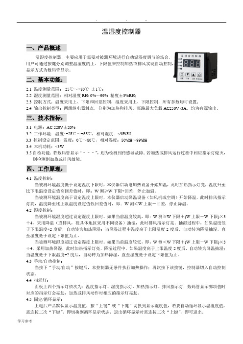
温湿度控制器一、产品概述温湿度控制器,主要应用于需要对被测环境进行自动温湿度调节的场合,用户可通过按键分别调整温湿度的上、下限值来控制加热或排风实现自动控制,显示方式为数码管显示。
二、基本功能:2.1 温度测量范围:-25℃~+80℃±1℃;2.2 湿度测量范围:相对湿度RH: 0%~99% 精度±3%RH;2.3 控制方式:温度采用上、下限和回差控制,湿度采用上、下限控制,所有参数均可设置;2.4 输出控制类型:两组继电器触点,分别为加热和排风,每路最大负载AC250V /3A,均为有源输出。
三、技术指标:3.1电源:AC 220V±20%3.2 工作环境:温度:-25℃~+55℃,相对湿度:<95%RH3.3控制设定范围:温度:0℃~80℃,相对湿度:50%RH~99%RH3.4 本机功耗:<3W3.5自检功能:若数码管显示“–––”,则为检测到传感器故障;若加热或排风运行过程中相应指示灯熄灭,则检测到加热或排风故障。
四、工作原理:4.1 温度控制:当被测环境温度低于设定温度下限时,本仪器启动电加热设备开始加温,此时加热指示灯亮,温度升至比下限温度设定值高回差值时,即:W测≥W下限+回差,停止加温。
当被测环境温度高于设定温度上限时,本仪器启动降温设备(如风机或空调)开始降温,此时排风指示灯亮,温度降至比上限温度设定值低回差值时,即:W测≤W上限-回差,停止降温。
4.2 湿度控制:当被测环境湿度超过设定湿度上限时。
如果当前温度较高,即:W测≥W下限+(W上限-W下限)×3÷4,采用降温(或排风,视具体地区采用不同设备)抽湿,此时排风指示灯亮;抽湿过程中,如果温度低于下限温度+2度后,自动转为加热降湿;当降湿过程中温度高于上限温度-2度后,自动转为降温抽湿,直至湿度低于设定下限值为止。
当被测环境湿度超过设定湿度上限时。
如果当前温度较低,即:W测<W下限+(W上限-W下限)×3÷4,采用加热降湿,此时加热指示灯亮,降湿过程中,如果温度高于上限温度-2度后,自动转为降温抽湿;当温度低于下限温度+2度后,自动转为加热降湿,直至湿度低于设定下限值为止。
可编程温度控制器使用方法
可编程温度控制器使用方法一、可编程温度控制器的初步认识。
1.1 这可编程温度控制器啊,就像是一个温度的小管家。
你看它,外观上可能有个显示屏,能让你直观地看到各种信息呢。
它的大小不一,但都很精巧,摆在那儿就像个默默守护温度的小卫士。
1.2 它的功能可强大啦。
不像那些普通的温度控制设备,只能简单地调个温度。
这个可编程的家伙,可以按照你设定的程序来控制温度,就像你给它下了一道道指令,它就乖乖听话。
二、开始使用前的准备。
2.1 首先呢,你得把它安装好。
这就跟盖房子打地基似的,安装的地方得合适。
要找个通风良好、干燥的地方,可不能让它受潮或者被什么东西捂着,不然它就像人被捂住了嘴,没法好好工作啦。
2.2 接着就是连接电源。
这一步可不能马虎,就像给手机充电得插对线一样。
要确保电源连接稳定,电压得符合它的要求,不然它就会像个闹脾气的小孩,工作起来不正常。
2.3 然后就是传感器的安装。
传感器就像是它的小触角,用来感知温度的。
你得把传感器安装在能准确测量温度的地方,要是装错了地方,那它得到的温度信息就不准确,整个控制就会乱了套,这就叫“差之毫厘,谬以千里”啊。
三、设定温度程序。
3.1 进入到设定程序这一步,就像你在教小孩子做事情一样。
你得先选择模式,有制冷模式、制热模式等。
比如说你想让一个小空间保持凉爽,那就选择制冷模式。
这时候你要根据实际需求来设定目标温度,不能太贪心,温度设得太低或者太高都不合适,要恰到好处,就像炒菜放盐,不多不少才正好。
3.2 再就是设定时间程序。
你可以设定它在某个时间段内保持某个温度。
比如说你想在晚上睡觉时让房间保持温暖,你就可以设定从晚上10点到早上6点保持一个舒适的温度。
这就像给它定了个闹钟,到点就按照你的要求来控制温度。
四、使用中的注意事项。
4.1 在它工作的时候,你要时不时地去看看它。
就像照顾小宠物一样,看看显示屏上的温度是不是在正常范围内。
如果发现有什么异常,可不能坐视不管,要赶紧检查是哪里出了问题。
PURPOSECRT - 04 温控器说明书
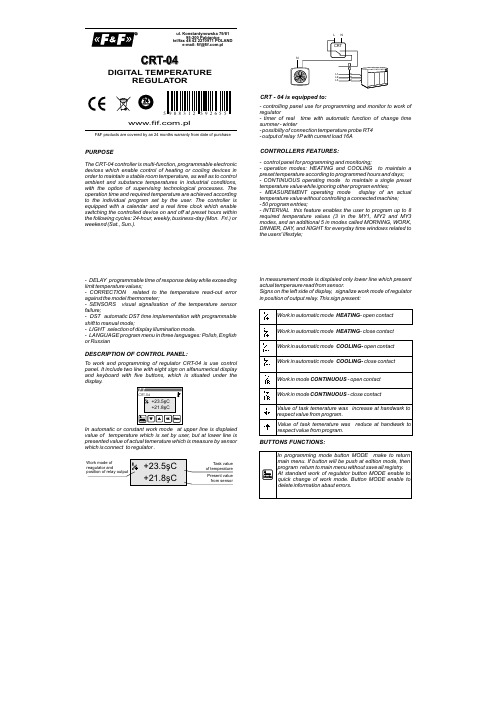
PURPOSECRT - 04 is equipped to:CONTROLLERS FEATURES:The CRT-04 controller is multi-function, programmable electronic devices which enable control of heating or cooling devices in order to maintain a stable room temperature, as well as to control ambient and substance temperatures in industrial conditions, with the option of supervising technological processes. The operation time and required temperature are achieved according to the individual program set by the user. The controller is equipped with a calendar and a real time clock which enable switching the controlled device on and off at preset hours within the following cycles: 24-hour, weekly, business-day (Mon. Fri.) or weekend (Sat., Sun.).- controlling panel use for programming and monitor to work of regulator- timer of real time with automatic function of change time summer - winter- possibilty of connection temperature probe RT4- output of relay 1P with current load 16A- control panel for programming and monitoring;- operation modes: HEATING and COOLING to maintain a preset temperature according to programmed hours and days;- CONTINUOUS operating mode to maintain a single preset temperature value while ignoring other program entries;- MEASUREMENT operating mode display of an actual temperature value without controlling a connected machine;- 50 program entries;- INTERVAL this feature enables the user to program up to 8 required temperature values (3 in the MY1, MY2 and MY3 modes, and an additional 5 in modes called MORNING, WORK, DINNER, DAY, and NIGHT for everyday time windows related to the users' lifestyle;- DELAY programmable time of response delay while exceeding limit temperature values;- CORRECTION related to the temperature read-out error against the model thermometer;- SENSORS visual signalisation of the temperature sensor failure;- DST automatic DST time implementation with programmable shift to manual mode;- LIGHT selection of display illumination mode.- LANGUAGE program menu in three languages: Polish, English or RussianCRT-04.plul. Konstantynowska 79/81tel/fax 48 42 2270971 POLANDe-mail:***********.pl95-200 PabianiceF&F products are covered by an 24 months warranty from date of purchaseDIGITAL TEMPERATUREREGULATORDESCRIPTION OF CONTROL PANEL:To work and programming of regulator CRT-04 is use control panel. It include two line with eight sign on alfanumerical display and keyboard with five buttons, which is situated under the display.In automatic or constant work mode at upper line is displaied value of temperature which is set by user, but at lower line is presented value of actual temerature which is measure by sensor which is connect to regulator .In measurement mode is displaied only lower line which present actual temperaure read from sensor.Signs on the left side of display, signalize work mode of regulator in position of output relay. This sign present:BUTTONS FUNCTIONS:In standard work mode regulator enable to make cyclic programs which wereset by user at memory. Possible is make to 50 programming registry which needed define:- day or days when will be make program. Possible is choose sibgle days( from monady to fsunday), work days, weekand and another.d- time of start program- one of eight definite by user value of task temerature (INTERVAL)FUNCTIONING:ATTENTION! Numberof program are given automaticly by regulator when the is set new program.Programs are make in chronology, it mean they start with set time and date. Stop of program is make at the moment when the nextprogram is start.EXAMPLE:The First program with temperature …morning” is execute at work days (RO) and is start at 6.00 am. The Second program with temperature …night” will be execute every day since 9 pm. The third program will be execute only weekand since 9 am. The last program with temperature “work” will be execute every Monday since 3 pm.u n d a y o u r . 0:00u n d a y ,o u r 9:00 a mo n d a y ,o u r 09:00 p mo n d a y ,o u r 06:00 a mo n d a y ,o u r 03:00 p mo n d a y o u r 09:00 p mu e s d a y ,o u r 06:00 a mu es d a y ,o u r 09:00 p me n d e s d a y ,o u r 06:00 a mExecute programATTENTION! Programs which were save at higher position are processing earlier than programs from lower position. It mean, if we have two programs with the same action and time, than will be execute program with higher number.Pass to programming mode is possible by push button MENU.Structure of main menu:PROGRAMMINGTo select position from menu we use buttons “UP” and “DOWN”. If you want pass to selected position then you need push button OK. Pass to main menu is possible by push button MENU.Menu -> MODERegulator make measurement result temperature between actual temperature from sensor C1 and task temperature Tprog. Which is set to executing program and for set width of hysteresis area H.Regulator in HEATING mode:T T P1T Regulator make measurement result temperature between actual temperature from sensor C1 and task temperature Tprog. Which is set to executing program and for set width of hysteresis area H.If temperature on input of sensor C1 fall to lower than value (Tprog H), it cause close of joint P1. Open a joint P1 will make after the temperature on input C1 will be higher than temperature (Tprog + H).Regulator in COOLING mode:T T T P1If temperature on input of sensor C1 increase to higher than value ( Tprog+ H), it cause close of joint P1. Open a joint P1 will make after the temperature on input C1 will be lower than temperature (Tprog - H).Regulator make measurement result temperature between actual temperature from sensor C1 and constant temperature Tconst, which is set by user at the moment when is select work mode and for set width of hysteresis area H.In this mode device is use only to display value of temperature.Joint P1 stay in open position.TT P1T Regulator in CONTINUOUS mode:Regulator in MEASUREMENT mode:If temperature on input of sensor C1 fall to lower than value ( Tconst H), it cause close of relay joint P1. Open of realy joint P1will make after the temperature on input C1 will be higher thantemperature (Tconst + H).Choose work mode:1. By button MENU pass to main menu of regulator.2. Push a button OK to enter pass to menu3. By buttons “UP” and “DOWN” choose work mode and enter by button OK.4. When you choose Continuous mode you should set temperature which will be hold by regulator.The first of all you set a digit of decimal position ( digit which is edit is signalize by blinking underline sign), afterwards you pass to set next position by push a button MENU. After set all digits oftask temperature enter by button OK.Menu -> ProgramOrders from menu Program make possibility to create, edit and delete programs which define behaviour of regulator in automatic work.CREATE A NEW PROGRAM:Stage of create a new program are following:1. After pass to Menu -> Program and select program- > set and enter by button OK, by buttons “UP” and “DOWN” set a minute, enter by OK and set hour for start program ( value which is edit is signalize by blinking underline minute and hour)2. Push button OK and by buttons “UP” and “DOWN” set a day when will be start program. We have following option:Monday,Tuesday,Wednesday, Thursday, Friday, Saturday, Sunday Program will be start in choosen dayProgram will be start in every work day (from Monday to Friday).Program will be start at Saturdy and Sunday Program will be start at every day of week.RO - Work days WEeekendy DO - free dayEnter selected day by button OK.3. By buttons “UP” and “DOWN” set a task temperature for present program.ATTENTION!! Possible is choose one of eight values of temperature which were definite in MENU -> interval. Everyone of values are signed by parameters: Morning, Work, Dinner, Day, Night, Mine1, Mine 2, mine 3. Changes value of temperature for present program is automaticly set for every programs with this parameter.4. Save program in memory by button OK.At any time possible is out from create new program mode, without save all registry, by button MENU.Example of create a new program:EDITION OF EXIST PROGRAM:1. After pass to menu Program need to choose option Program -> edit and enter by button OK.2. By buttons “UP” and “DOWN” select program which will be edit and enter by button OK3. Next operation are similarly as create new program.Edition of program without save all change, could break by push button MODE.DELETE PROGRAM1. After pass to menu Program need to choose option Program -> delete and enter by button OK.2. By buttons “UP” and “DOWN” select program which will be delete and enter by button OK.3. Confirm delete of program by button OK.ATTENTION! Delete program cause automaticly change numbers of rest programs.Menu -> IntervalOrdered value of temperature in programs which are make by regulator CRT-04 is not define in program code, but by group of eight parameters which comes from menu interval.If you want change value of temperature which is connect with selected parameter need to:1. After pass to menu Interval by buttons “UP” or “DOWN” select edited parameter.2. Enter by button OK.3. By buttons “UP” or “DOWN” set correct value for decimal position of degree.4. If you wont pass to edit temperature on next position, push button Menu (edit position will be signalize by blinking underline sign)5. Repeat procedure from point 3 and 4 need set all numbers with new value of ordered temperature.6. Enter all changes by button OK.Push a button any time in edit mode cause out from edition mode without save all changes.Example of set a new value of temperature:Menu -> TimerThis mode is use only for change date and time.Set a DATE:1. After pass to menu timer by buttons “UP” or “DOWN” select timer -> DATE and push button OK.2. By buttons “UP” or “DOWN” set correct month, enter OK3. By buttons “UP” or “DOWN” set correct day.Example of procedure:SET TIME:1. After pass to menu timer by buttons “UP” or “DOWN” select menu TIMER and push button OK.2. By buttons “UP” or “DOWN” select timer -> Hour and push button OK.3. By buttons “UP” or “DOWN” set correct minute, enter OK4. By buttons “UP” or “DOWN” set correct hour.5. Push button OK.. cause enter changes and start count time from set value.Example of procedure:AUTOMATIC CHANGE TIME FUNCTION:Regulator CRT-04 could automaticly change time from winter tosummer and from summer to winter. This function will be make automatic or handwork, it is set by user.If you want set function DST need to:1. After pass to menu timer by buttons “UP” or “DOWN” select function DST.2. Enter by button OK.3. By buttons “UP” or “DOWN” choose option Atomatic (if regulator have automatic change time function) or handwork (when change of time will not make).4. Enter by button OK..Menu -> SystemThis mode make possible to define additional functions of regulatorCRT-04.DELAYThis parameter make possibility to put delay of reconnection realyoutput by ordered time. In practic this function will be use at the situation when we wait for turn ON/OFF of heater, it will make when temperature go out from allow regulation area.Example with use time delay by value Tzw and regulator is presented at under picture. In this cause condition of enclose is fall a temperature under value (Tprog H) for time Tzw, but condition of excluse is increase temperature higher than value (Tprog + H) for time Tzw.T T P1T If you need set a delay time of reconnection follow procedure:1. Pass to menu -> System and by buttons “UP” or “DOWN” select option System -> Delay.2. Enter by button OK.3. By buttons “UP”and “DOWN” set value of delay.4. Enter by button OK.Push a button any time in edit parameter cause out from edition mode without save all changes.ATTENTION!: Delay time could be set in range 0 ÷ 15 min.,with step1 min.Example of setting delayHYSTERESISThis parameter make possibility to define precision and cleanliness with in will be reconnect output of relay at regulation of temperature. If value of hysteresis is smoler than precision is higher but enclose of heater component will be oftenly. But if the value of hysteresis is large that cause lower frequency of connection heater component and precision of regulation is lower.Examples characteristics with two different hysteresis areas:T T P1T S m a l l a r e a o f h y s t e r e s i sTT T L a r g e a r e a o f h y s t e r e s i sIf you need set value of hysteresis follow with procedure:1. Pass to Menu -> System and by buttons “UP” or “DOWN” select option -> Hyst.2. Enter by button OK.3. By buttons “UP” or “DOWN” set value of hysteresis.4. Enter by push button OK.At any time possible is out from edit parameter mode, without save all registry, by push button MENU.ATTENTION: Hysteresis could be set in range 0÷10°C, with step 0,1°C.Example of setting hysteresis:CORRECTIONThis parameter is use for correction indication from sensor. To set correction indication of sensor follow the procedure:1. Pass to Menu -> System and by buttons “UP” or “DOWN” select option System -> Correction2. Enter by button OK.3. By buttons “UP” or “DOWN” set value of correction.4. Enter by button OK.At any time possible is out from edit parameter mode, withoutsave all registry, by push button MODE.ATTENTION ! Correction of sensor indication could set in range 5.0 ÷ 5.0 °C, with step 0,1°C.Example of setting temperature correction:SELECT REPORT LANGUAGEThis parameter make possiblity to choose on of three language in which will be display reports. If you need change language you need pass to menu System -> Language by buttons “UP” or “DOWN” select language and enter by button OK. Return to main menu is possible by push button MODE.LIGHTING OF DISPLAYThis parameter make possibility to lighting a display of regulator. Possible is set lighting for all the time for display or lighting only for some second after push any buttonIf you need way of lighting you need to pass menu System -> Light and select by buttons “UP” or “DOWN” correct option and enter by button OK.. Return to main menu is possible by push button MODE.REATURN TO DEFAULT SETTINGSDefault settings make possibility to return all settings of regulator to target values. If you need restore default settings pass to menu System -> default settings and enter by button OK. Next by buttons “UP” or “DOWN” set value YES and push button OK.ATTENTION! Return to default settings cause delete all earlier configurations with saved programs.Rest of parameters of regulators are set with values:ModeHandwork Tzad (handwork)25,0°C Hysteresis0,0°C Delay0min Sensor correction0,0°C Correction of odered value0,0°CInterval20,0°C (everyone)Lighting of displayAll time DST AutomaticDate / Time01.01.2008 00:00QUICK CONFIGURATIONRegulator CRT-04 make possibility choose work mode and change value of order temperature without pass to programming mode.QUICK CHANGE VALUE OF WORK TEMPERATUREIf you need change work mode in standard work you need push button MODE, next follow with instructions as select work mode which is presented in programming mode section.QUICK CHANGE OF ODERED VALUETo change ordered value of temperature in standard work of regulator use buttons “UP” or “DOWN”. Pushing once time button “UP” cause increase ordered temperature by 0,5°C, but pushing button “DOWN” cause fall ordered temperature by 0,5°C. Increas temperature higher than default value is siganlize by display in upper line a sign , but fall temperature is siganlize by sign .ATTENTION!Handwork correction of ordered temperature will be force at all next work in automatic mode. Also after start program to next step of program, forced value will be change by value from handwork correction Return to deafult settins is possible in causes:- hadwork configuration to moment when arrow will disappear from display.- reconnection regulator to continuous work mode.,Example of quick configuration of ordered temperatureDISPLAY ACTUAL DATE AND TIMEDisplay to date and time, need to in standard work of regulatorpush button OK..ERRORS SYGNALINGAfter 3 sec. regulator return to earlier window.In the cause break or wrong work of sensor, regulator displayunderline report :In this cause first of all need to check connection of sensor.sensor DS18S20dimensions of sensorŘ5LiYY 3×0,34mm˛ l=2,5m; h=30mmsensor isolationtherm jacketcablePROBE RT4TECHNICAL DATAASSEMBLY:supply230V ACcurrent load<16Ajoint separated 1Prange of regulation temperature0÷60°Chysteresis setting range 0÷10°Cprecision 0,1°Cmodel correction±5°Cdelay reconnection- to set1÷15minpower consumption1,5Wworking temperature-20÷40°Cterminal screw terminals 2,5mm²dimensions 3 modules (52,5mm)fixing on rail TH-351. Take OFF the power.2. Regulator put on the rail in the switchgearbox.3. Connect supply: L to joint 1; N to joint 2.4 Out cable of temperature probe connect to realy with marksWHITE cable(7) to joint 8, BROWN cable (9) to joint 9 .5. System of enclose receiver connect in line to joints 11-126. Set program to regulation temperature.For use seprtated reconnection of joint 1P, were accept ininstruction configuration:ATTENTION!CRT-047WGB R89111210WIRING DIAGRAMATTENTION!Do not any change in device. It impend break or wrong work ofdevice, it will cause break contolled device or menace for user. Inthis cause producer is not responsible of arise accidents andcould refuse given warranty for regulator in cause submit a claim.A090701。
温度控制器安装和使用说明书

CONTROLLER LOCATIONS ∙ The temperature controller should be out of reach of small children.∙ Avoid locations where the temperature controller may become hot (near an oven or radiant heater). ∙ Avoid locations in direct sunlight. The digital display may be difficult to read in direct sunlight.∙ DO NOT install controller against any metal material unless properly grounded per local electrical codes. ∙ Avoid locations where the temperature controller could be splashed with liquids and/or chemicals. ∙DO NOT install in locations where the temperature controller can be adjusted by the public.CABLE LENGTHS AND SIZESThe cable for the temperature controller should be a non-polarized two-core cable with a minimum gauge of 22 AWG. The maximum cable length from each temperature controller to the water heater depends on the total number of wired controllers connected to the water heater. (Refer to the installation and operation manual of the water heater for moredetailed information regarding additional controllers.)Before installation, please make sure that all parts are located inside the product box. If any items are missing or damaged, contact your local dealer/distributor or call Rinnai Customer Care at 1-800-621-9419.123ITEMS INSIDE PRODUCT BOXTOOLS/MATERIALS REQUIRED456❒ Phillips head screwdriver ❒ Drill ❒ Wire Stripper/Crimper ❒ Additional Wire (22 AWG Minimum)71.Make 3 holes in the wall as shown below. (Reference template on last page.)2. Remove the face plate from the temperature controller using a screwdriver.When performing the steps in this section, you must follow the wiring guidelines established by the National Disconnect power to the water heater. Do not attempt to connect the temperature controller(s) with the power on.WARNING3. After disconnecting power to the water heater, connect the field-supplied wire to the stripped wire ends of the con-troller . Follow the wiring guidelines established by the National Electrical Code (NEC).4. Using the provided screws and wall anchors, mount the controller to the wall.5. Remove the protective film from the controller.Number of Controllers Maximum Cable Length for Each Controller toWater Heater1 328 ft. (100 m)2 164 ft. (50 m)3 or 465 ft. (20 m)Controllers wired in seriesControllers wired in parallelControllers canonly be wired in parallel; theycannot be wired inseries.FilmCover Plates3.31 i n . (84m m )1.65 i n . (42m m )1.Remove the front panel of the water heater.2. Locate the terminals for control in the water heater.3. Thread the cable through the base of the water heater4. Connect controller wires to the terminals for control.For additional information regarding installation and/or operation of the temperature controller, please refer to the Installation and Operation Manual of the water heater. 1.If the water heater is off, press the “On/Off” button to turn on.2. The “Priority” button enables a controller if multiple controllers are being used. If the “Priority” light is off, then press the“Priority” button on the temperature controller. The green “Priority” light will glow indicating that this controller iscontrolling the temperature and that the water heater is ready to supply hot water. The priority can only be changed while no hot water is running. 3. Press the (Up) or (Down) buttons to obtain the desired temperature setting. All hot water sources are able toprovide water at this temperature setting until it is changed again at this or another temperature controller. 4. To operate the water heater, open any hot water fixture. The water heater will then activate and the water heater “In Use”indicator will illuminate on the controller show that the water heater is providing hot water. For further information on controller operation, refer to the installation and operation manual of the water heater.Enables controller when multiplecontrollers are usedDisplayDecreases hot water temperatureIncreases hot water temperatureTurns the water heater on or off“In Use” IndicatorInstalling Four Controllers 1.If 4 MC-601’s are installed, press the “Priority ” and “On/Off ” buttons on the fourth controller at the same time until a beep sounds. (See above)2. Check that the displays on all four controllers are lit and displaying the temperature setting when switched on. If any ofthe controllers displays two dashes then repeat step 1. Note: If a controller is replaced, repeat these steps for the replacement controller.In applications where a Rinnai Control-R™ module is installed in place of a 4th controller and there is: ∙ Option 1 in Rinnai Control-R™ mobile app - “No Recirculation” - Perform Step 1 above.∙ Option 2 in Rinnai Control-R™ mobile app - “Recirculation” - Step 1 above is not necessary.HOTBURNSecuring Screw Securing Screw Wiring Hole Overall Controller Dimension: ∙ W: 3.54 in. ∙ H: 4.72 in. ∙D: 0.70 in.Ø.20Ø.50Ø.20100000570(02)9/2022。
温控器使用说明书
一周编程电子智能室内温控器LOGIC 578001使用指南引言感谢您选择了我们的产品及对我们的信任与支持。
本装置是电子式定时恒温器,可设置一星期为周期的运行程序。
通过该装置,可对安装环境内的温度进行十分精确的调节控制,满足用户对创造一个舒适生活环境的要求。
符合标准:符合欧盟法令:EN 60730-1 标准及其修订内容欧盟B.T.73/23/EEC号法令EN 60730-2-7 标准欧盟 E.M.C.89/336/EEC号法令及93/68/EEC修改法令EN 60730-2-9 标准产品规格:电源:二节LR6型1.5V碱性电池温度调节范围:10至35℃显示屏显示之环境温度:0至40℃(分辩率0.1℃)温度修正频率:每分钟一次微分:0.2至0.4K探针传感器:NTC3%保护等级:IP20绝缘等级:热梯度:1K/15分输出:转换继电器触点容量:8(2.5)A250V~作用类型:1BU绝缘条件:正常环境最大工作温度:50℃储存温度:0-60℃防冻温度:6℃恒定运行程序:以一星期为周期设置软件等级:A液晶显示屏夏季/冬季(采暖/空调)切换程序设置中的最小增减允许时间:1小时安装:壁式安装安装及连接:安全预防措施在进行定时恒温器的连接之前,请确认受其控制的设备系统(采暖锅炉、泵和空调系统等)电源已断开,并需检查这些设备的使用电压是否与定时恒温器底座上表明的电压相符(最大250V~).(图4)安装位置定时恒温器须安装在远离热源(暖气装置、阳光、厨房)和门窗之处,安装高度离地面约1.5米。
(图5)安装见图6-7-8电气连接将受定时恒温器控制的设备系统电线与定时恒温器的1号及2号接线柱连接见接线图10所示U=受定时恒温器控制的设备1=共用接线柱2=常开接线柱3=常闭接线柱重要事项:请务必严格遵照相关现行法律的规定及安全规范安装定时恒温器。
电池更换:当在显示屏上闪烁显示“”标志时,定时恒温器还可正常工作约一个月左右,然后将会停止工作并固定显示“”。
尚方101T温控器说明书电子版

尚方101T温控器说明书电子版
一、功能说明
1、温度控制
压缩机经过延时后,当库温大于(控制温度+温差),压缩机启动。
库温小于控制温度,压缩机停止。
为保护压缩机,压缩机每次停止的时间必须超过延时时间(E4参数)才能重新启动。
2、定时停机化霜
工作了一个化霜间隔(参数F2)的时间后自动进入停机状态,压缩机停止;经过一定时间(参数F1)后,进入自动制冷状态。
当化霜间隔设置为“00”时,取消停机化霜功能。
同时按住阳键和立键持续六秒后,进入参数设定,闪烁显示F1;再按回键循环显示F2、F1;按三角键和立键,可显示该参数的数值并修改、存储数据;六秒内未再按任何键,返回正常操作方。
3、非正常工作模式
库温探头短路或高温超限(大于100C)显示“HH”;探头开路或低温超限(小于一45C)显示“LL”。
此时进入定时工作模式,压缩机运行45分钟,停止15分钟。
二、安装使用注意事项
1、为防止高频干扰,探头线不可与电源线或控制线捆扎并行,要分开布线。
2、探头安装时应头朝上、线朝下。
3、如安装需要,可延长探头线最长至100米,不须重检。
.
4、温控器不能装在有滴水的地方。
室内温控器安装使用说明书

室内温控器(安装使用说明书)
产品简介
●该温控器可应用于控制阀门,或者双管风机中的阀门和风门。
●温控器可控制一个启/停阀门,以控制所需要的温度,风机也可以由温控器控制,在有一些情况下,可以连续运转,或风机随恒温器循环运转。
●温控器备有一个手动三速风机开关和一个系统总开关。
这个功能是通过操作温控器面板上的冷热开关来完成的。
●双金属膜片充气膜盒能按要求确保准确的温度控制。
●造型精美别致,使温控器更加完美地安装于室内环境中,特别适合于写字楼的办公室和宾馆饭店的客房内使用。
●温控器可直接安装在墙上或接线盒上。
●所有型号的温控器都具有热量预感器,热量预感器能进一步改进热冷温度控制。
安装事项
●该温控器是风机盘管或空调系统中温度控制元件,必须安装在通风良好的位置,标高距面1.5米,避免将恒温器安装在出风口,阳光照射或有冷/热源的地方,可安装在一个入墙式,尺寸75×75×35mm或55×105×48mm的标准接线盒上。
技术数据
控温精度:±1℃
偏差:在20℃时,≤1℃
工作范围:10-30℃
感温元件:充气膜盒
材料和颜色:底座及盖均为乳白色PC塑料
额定电压和电流: 220V-240V 3(2)A,50-60Hz
电线连接: 接线端子,可接受最大1.5mm2粗的电线
运输保存: 在运输和贮存中温度要控制在-20℃到50℃之间
外形尺寸。
四路智能温控仪使用说明书

四路智能温控仪使用说明书一、概述四路智能温度控制仪,可以同时配接4路传感器,独立的自整定模式和独立的PID参数,同时控制4路温度,整机控制性能精确可靠。
二、技术性能1、输入类型:CU50(-50.0~150.0℃)、Pt100(-19.9~600.0℃)、K(0~1300℃)、E(0~700.0℃)、J(0~900.0℃)、S(0~1600℃)、所配传感器必须为隔离型的。
2、控制方式:二位式控制、PID控制3、输出方式:继电器240V 5A(阻性负载)4、测量精度:±0.5F·S±1字,附加冷端补尝误差±1℃5、工作电源:AC220V 50Hz 功耗:小于4W6、工作环境:0~50℃,相对湿度≤85%RH,无腐蚀性及无强电磁辐射场合7、外型尺寸:160×80×110 开孔尺寸:152×7696×96×110 开孔尺寸:92×92三、仪表使用1、一级菜单设置按功能键(SET键)3秒,进入一级菜单,此时‘第1路显示窗’和‘第2路显示窗’分别显示参数符号和参数值,可分别按◄(移位键)、▲、▼三键来更改参数值,修改完成后按SET键保存进入下一个参数;同样方法修改其它参数。
一级菜单, 按功能键(SET键)3秒进入序号提示符名称设定范围说明出厂值一级菜单1 Sn 输入规格 0~4 CU50、Pt100、K、E、J、S 随机2 ALP 报警定义 0~60:无报警;1:上限报警;2:下限报警;3:上偏差报警;4:下偏差报警5:区间外报警6:区间内报报警13 t 输出周期0~120 S 设定继电器控制时的动作周期20S4 dp 小数点位置 0~1 0. 无小数点; 1.有小数点05 P-SH 设定值上限P-SL~满量程此参数限制了设定值的上限随机6 P-SL 设定值下限量程起点~P-SH此参数限制了设定值的下限随机7 COOL 正反控制0~1 0.反作用(加热输出)1.正作用(制冷输出)8 Add 地址1~64(1~9999分)仪表在集中控制系统中的编号(在带微型打印功能时,作打印间隔时间)12、二级菜单设置各通道参数分别按CH1、CH2、CH3、CH4三秒进入相对应的通道菜单项,可按◄、▲、▼三键来更改参数值修改完成后按SET键保存进入下一个参数;各参数见下表:二级菜单, 按CH1键或CH2、CH3、CH4键3秒进入序号提示符名称设定范围说明出厂值二级菜单各通道对应的参数设定10 SP+N N通道控制点设定范围由P-SL、P-SH决定每一通道控制点温度设定参数随机11 AL+N 报警设定值范围由P-SL、P-SH决定由AL-P参数决定报警方式随机12 SC+N 误差修正值±20.0 传感器的误差修正值013 P+N 比例带0~200.0比例带决定了系统比例增益的大小, P越大, 比例的作用越小,过冲越小, 但太小会增加升温时间P=0时,转为二位式控制15.0 14 I+N 积分时间0~3000设定积分时间,以解除比例控制所发生之残余偏差, 太大会延缓系统达到平衡的时间, 太小会产生波动24015 d+N 微分时间0~200S 设定微分时间,以防止输出的波动,提高控制的稳定性30 16 Hy+N 主控与报警回差0.1~50.0 主控只有二位式控制时才有意义 1.0 17 At+N 自整定参数0~1 0:关闭自整定 1:开启自整定0四、注意事项1、所配传感器必须为隔离型的。