Lec 4-1Byron
菲尼克斯PLC继电器-

灵活 性意味 着根据 应用场 合既 可以为 每 个通道 自由选 择输入电 压,也可以 装入不 同 的机电式继 电器或者半导 体继电器 (光电 耦 合器) 。固 定的可编程控制 器插件板在这 方 面也是 望尘莫 及。灵活性 也意味着 系统可 以 随时 扩展,并且 可以随 时方便、便 宜地更 换 可插拔式继电器和光电耦合器。
PLC 接口 带回拉式弹簧连接 由 底座接线端子 PLC-BSP…/21 和 可插拔微型继电器组成, 用于安装在 3 上
输入电压 UN
12VDC 24VDC 24VAC/DC 48VDC 60VDC 120VAC/110VDC 230VAC/220VDC2)
12VDC 24VDC 24VAC/DC 48VDC 60VDC 120VAC/110VDC 230VAC/220VDC2)
VARIOFACE 系统接头
(164,)2 mm
可插拔继电器 和光电耦合器,
6.2/14mm
插拔式桥接系统
两个转换 触点 传感器型 执行器型 通用型
按实际应用优化的 系列产品
I
250VAC/6A(10A)
可选用螺钉连接或者回拉式 弹簧连接两种形式
U 通断容量高
一体化集成输入电路 和保护电路
DINVDE0106-101
执行 器 (例如 电磁阀、接 触器等)的 所 有连接线 (包括回线) 都被直接连接在 PLC 执行器接口上。
传感 器 (例 如接 近开 关、限位 开关 等) 的所有连 接线 (包括开 关的供电)都直 接在 PLC 接口上有相应的连接位置。与传统的耦 合元 件相比,可以 节省两 个输出 接线端子 或 者馈 入连接端 子,同时节 省了中 间接线工 作 和宝贵的开关柜空间。
LE4-1K接近开关

18mm非齐平安装
NAMUR sensors must be operated with approved switch amplifiers. Please find suitable devices below:
窗体顶端
参数表节选:的技术参数
开关功能
常开(NO)常闭(NC)
输出类型
NAMUR
额定工作距离
4-20mm
安装
非齐平
可靠动作距离
0 ... 2,88 mm
输出类型
2线
安装条件
A
20 mm
B
80 mm
C
12 mm
F
70 mm
额定电压
8,2 V(Ri约1 kΩ)
工作电压
7 ... 12 V
开关频率
0 ... 1 Hz
电流消耗
未检测到测量板
≤ 1 mA
检测到测量板
≥ 2,4 mA
平均失效时间(天)
环境温度
-25 ... 70 °C (-13 ... 158 °F)
ቤተ መጻሕፍቲ ባይዱ连接类型
电缆PVC , 2 m
导线截面积
0,34 mm2
外壳材料
PBT
感应面
PBT
防护等级
IP68
电缆
弯曲半径
> 10 x电缆直径
用在危险区域
参见指令手册
等级
1G; 2G; 1D
3299 a
使用寿命(...月...天)
20 a
诊断范围
0 %
符合标准
NAMUR
EN 60947-5-6:2000
IEC 60947-5-6:1999
Akzo Nobel Coatings Inc. Resicoat R4-ES HJF42R 防腐蚀

Functional Powder CoatingsProduct Datasheet20, Culvert Street T+1 855-294-8934Nashville, TN 37210F+1 615-564-4181USAResicoat ®R4-ESfor Electrostatic Spray Application on Preheated Surfaces Code: HJF42RProduct DescriptionResicoat ® R4 is a high quality thermosetting epoxy powder coating for the corrosion protection of valves and fittings, manufactured from cast iron or steel. The powder coating is available to be applied in one layer on a preheated surface by electrostatic spray application. Typical film thickness achieved is in the range of 250 – 500 µm. The resultant thermoset epoxy has a high mechanical resistance with excellent electrical insulation properties. Drinking water approvals are available to confirm the coatings suitability, as a hygienic and environmental friendly coating. The outstanding adhesion of Resicoat ® R4epoxy powders to the metal substrate provides long term protection of the coated component. It ensures a reliable conservation to the function and value of the parts for the common water and gasdistribution network. The applicator of Resicoat ®R4 benefits from a modern and environmentallyfriendly process. It is possible to overcoat Resicoat ®R4 with polyester powder and liquid coatings to achieve UV protection.Typical valueMethod Powder PropertiesBinder System Epoxy resinDensity1.45 – 1.55 g/cm³ASTM D5965Gel time at 392° F (200° C )25 – 40 sec.ASTM D4217Particle size distribution D10 = 10 – 15 µm D90 = 135 – 160 µm Malvern ISO 8130-1Storage stability 6 months at ≤ 74 °F (23 °C)Safety precautionsSee Material Safety Datasheet (MSDS)Application DataPreheating temperature object 392 – 428 °F (200 – 220 °C) object temperaturePost cure conditions objectThe coating is self curing, if the wall thickness of the steel/cast iron is greater than 8 mm. If the wall thickness of the steel/cast iron is less than 8 mm, additional curing of 3 to 8 minutes at 392 °F (200 °C) object temperature is required.1. Pre-cleaning The surface must be free of oil, grease, salt, and other impurities.2. BlastingMolding sand, rust and sharp edges must be removed with angular steel grit. The graphite from the cast iron must beremoved from the blasting material according NACE No.2/ SSPC-10/Sa 2.5. Recommended anchor profile of ≥60 µm should be stored max. 4 hours before pre-heating (dust-free and dry).3. Pre-heating This form of heating produces a uniform, defined temperature in the component. Any oxidation should be avoided.4. Coating applicationImmediately after preheating, the coating process starts without loosing any object temperature. The coating is done in the shortest possible time in a single pass with no interruptionFunctional Powder Coatings20, Culvert Street T+1 855-294-8934Nashville, TN 37210F+1 615-564-4181USATypical valueMethodCoating Process5. Coating cureCuring is achieved by the heat contained in the object. If the heating capacity of the work piece is sufficient. To confirm fully curing, MIBK is dropped for 30 sec. on the film surface with no visible change.Material PropertiesColorblueRecommended film thickness 10 – 14 mils (250 – 350 µm)Flowsmooth Gloss at 90° angle 70 – 90 units DIN 67530Cross cut test Gt 0DIN EN ISO 2409Impact resistance> 5 Joule > 2.26 Joule > 18 JouleDIN 30677-2ASTM D279420 inchpoundASTM G14 modified1/8 in (3.2 mm) steel plate Abrasion resistance < 40 mg ASTM D4060CS-17, 1000 g, 1000 cycles Dielectric strength≥ 30 kV/mm IEC 60243-1Volume resistivity (DC voltage) 1.1 x 10¹⁵ASTM D257Elongation> 5 %DIN 30671Indentation resistance 48 h, 158 °F (70 °C)24 h, 140 °F (60 °C)< 30 %< 10 %DIN 30677-2/DIN EN 14901ASTM G17Compressive strength > 100 MPa ASTM D695Shear adhesion> 35 MPa ASTM D1002Heat aging in air (90 d), water fulfilled DIN EN 14901Thermal stability under heat aging pass AS/NZS 4158:2003Weathering (Xenon test), 100 d pass ASTM D2596-99HardnessF Pencil Strain polarization pass WIS 4-52-01Cathodic disbonding 30 d, 74 °F (23 °C)≤ 10 mm DIN 30677-2, GSK Hot water immersion 90 d, 158 °F (70 °C)pass AWWA C550-05Adhesion> 20 MPa ASTM D4541Adhesion after 7 d,194 °F (90°C)water≥ 16 MPaISO 4624, GSK Tensile strength approx. 500 kg/cm³ASTM D2370Penetration< 5 %ASTM G17Functional Powder Coatings20, Culvert Street T+1 855-294-8934Nashville, TN 37210F+1 615-564-4181USATypical valueMethodMaterial PropertiesDisinfectant resistanceaccording DVGW work sheet W 291(chlorine dioxide, sodium hypochlorite)no change of surface,no chalkingafter 10 test stages à 15 h The following migration test with demineralised water showed no defects of the film. The concentration of the examined parameters in the tested water were below the limits of the epoxy guideline for ancillaries for pipes DN > 300 mm (in main trunks).Water condensation test (Cleveland test), 21 d no changeASTM D4585Salt spray resistance, 2000 h no blistering, no loss of adhesionBS 3900:F4Salt spray test, 4000 hno under-rusting on the cut DIN EN ISO 9227(steel substrate)Water absorption, 100 d, 74 °F (23 °C)pass AS/NZS 3862Chemical resistance (pH 3–13, 23° C)fulfilledEN 598Conformities ·AWWA C116·AWWA C550-05·EN 14901·ISO 12944-2, table 1(standard does not include powder coating systems)It is assumed that Resicoat ® R4 is suitable to meet the high atmospheric corrosivity category C4 (typically in industrial areas and coastal areas with moderate salinity) and the very high atmospheric- corrosivity -categories C5-I (industrial) and C5-M (marine) if applied as a holiday-free coating at a film thickness> 400 µm. A sufficient film thickness is highly required to ensure good edge coverage. For gloss and color stability a UV-resistant polyester topcoat has to be applied.Drinking Water ApprovalsUS: ANSI/NSF 61 Drinking Water System Components – Health Effects, NSF DE: UBA-Coatings Guideline, Approval no.: C-138801-06, Hygiene InstitutDE: DVGW directive work sheet W 270, Approval no. W-211795-11, Hygiene Institut UK: BS 6920, Approval No. 1112500, WRASDate of issue:July 10, 2015Authorized by:GK Revision No.:3Disclaimer: This Product Data Sheet is based on the present state of our knowledge and on current laws. The data referring to Powder Properties, Application Data and Physical Tests is based on lab based samples. Factors such as quality or condition of the substrate may have an effect on the use and application of the product. It remains the responsibility of the user to test thoroughly if the product is applicable for the intended use. The use of the product beyond our recommendation releases us from our responsibility, unless we have recommended the specific use in writing. It is always the responsibility of the user to take all necessary steps to fulfil the demands set out in the local rules and legislation. We are not liable for any application-technological advice. The Product Data Sheet shall be updated from time to time. Please ensure you have the latest version before using the product. All products and Product Data Sheets are subject to our standard terms and conditions of sale (GCS). You can receive the latest copy of GCS via internet or our post address. Brand names mentioned in this Product Data Sheet are trademarks of or are licensed to the AkzoNobel group.Resistance against chemical substances of Resicoat ®R4 at room temperature20, Culvert Street T+1 855-294-8934Nashville, TN 37210F+1 615-564-4181USA Chemical resistanceAugust 01, 2014Page 1 of 3Acetic acid 10 % 2 years no change Ammonia 10 % 2 years no change Ammonia 36 % 1.5 years no change Antifrogen L 50 % 1 year no change Antifrogen N 50 %1 year no change Benzol 1 month no change Bore oil 1 year no change Butanol6 months no change Carbon tetra chloride 1 yearno change Caustic soda solution 10 % 2 years no change Caustic soda solution50 %2 years no change Chlorine cleanser and disinfectant 1.5 years no change Citric acid2 years no change Deicer Safeway KF HOT 1 year no change Deicer Safeway SF (solid) 1 year no change Deicer Safewing MP II 1951 1 yearno change Dichromatic potassium 10 % 1 year no change Diesel2 years no change Engine oil SAE 20 1 year no change Ethanol 1 year no change Ethyleneglycole 1 yearno change Formaldehyde 37 % 6 months no change Formic acid 5 % 2 years no change Formic acid 10 %1.5 years no change Glycerol 1 year no change Glysantin 1 yearno change Hydrochloric acid concentrated1 week no change Hydrochloric acid 10 %2 years no change Hydrochloric acid 25 % 1.5 yearsno change Hydrofluoric acid 1 % 1 day no change Hydrogen peroxide 3 % 1 year no change Hydrogen peroxide10 %1 yearfadedLactic acid10 % 1 week no changeMethanol 1 week no changeMethyl tert-butyl ether (MTBE)100% 6 months softeningNitric acid10 % 1.5 years no changeNitric acid25 % 1 year no changeOxalic acid 5 % 6 months no changePalm oil at 90° C7 days no changePetrol 2 years no changePetroleum 1 year no changePhosphoric acid10 % 2 years no changePhosphoric acid50 % 2 years no changePotassium hydroxide10 % 1 year no changePotassium hydroxide25 % 1 year no changePotassium hydroxide50 % 1 year no changePropanol 1 year no changeSea water 2 years no changeSodium acetate10 % 1 year no changeSodium carbonate20 % 1 year no changeSodium hypochlorite (15 % Cl2)10 weeks no changeSodium chloride 2 % 1 year no changeSodium chloride20 % 1 year no changeSodium formiate10 % 1 year no changeSuds 1 % 1 year no changeSulphuric acid 2 % 2 years no changeSulphuric acid20 % 2 years no changeSulphuric acid50 % 2 years no changeTartaric acid 5 % 1 year no changeToluol 1 year no changeTurpentine oil 1 year no changeUrea10 % 1 year no changeUrine 1 year no changeXylol 1 year no change 20, Culvert Street T+1 855-294-8934Nashville, TN 37210F+1 615-564-4181USA Chemical resistance August 01, 2014Page 2 of 3Our printed literature and technical information Sheets as well as our advisory services are offered to facilitate andsupport decision-making processes. All specifications provided reflect the state of our knowledge at the time of print. Anytechnical data and measured values supplied have been tested for compliance with current applicable standards, ifavailable. The information provided is not legally binding upon the party supplying such information.20, Culvert Street T+1 855-294-8934Nashville, TN 37210F+1 615-564-4181USA Chemical resistance August 01, 2014Page 3 of 3。
Racor 804MA Series 海洋型汽油筛胶水分离器说明说明书

Contact Information:Parker Hannifin Corporation Racor Division P .O. Box 32083400 Finch Road Modesto, CA 95353phone 800 344 3286 209 521 7860fax 209 529 3278****************/racorProduct Features:• Removes 99% of free water • Flow rates up to 540 GPH(2,044 LPH)• Includes 2 inlets and 2 outletsfor installation flexability • Water sight glass included as standard equipment• Optional vacuum andcompound gauges availableInstallation DiagramMounting InstructionsBack View16.0 in.(40.6 cm)79804MA Top View75804MA Top ViewTop ViewA:804MA - 5.5 in. (13.8 cm)75804MA - 20.25 in. (51.4 cm)79804MA - 31.75 in. (80.6 cm)B:All Assemblies -8.25 in. (20.9 cm)C:All Assemblies -7.11 in. (18.1 cm)Obtain good ventilation and 1. lighting. Engine must be off for 2. installation. DO NOT smoke or allow open 3. flames near installation.Filter assemblies should 4. be installed on vacuum side of fuel transferpump for optimum waterseparating efficiency. See Installation Diagram.Locate filter assembly5. between horizontal planes ofbottom of fuel tank and inlet of fuel pump, if possible. If filter assembly is installed in an application where fuel tank is higher than filter, a shut-off valve must be installed between tank and filter assembly INLET. This will be used when servicing replacement elements. Install assembly in a location 6. which provides accessibility and protection from heat, flames, or accidental impacts. Always adhere to applicablelocal piping regulations and codes. Use maximum fuel line size possible and avoid reducers and elbows in order to keep restriction values as low as possible.Apply thread sealant (no 7. thread tapes) to inlet and outlet fittings prior toinstalling onto filter assembly.When routing hose, avoid 8. surfaces that will move, have sharp edges, or will get hot (such as exhaust piping).Installation GuidelinesPriming The UnitServiceClose inlet fuel valve, if 1. applicable.Remove T-handle and lid 2. from top of filter assembly.Fill filter assembly with clean 3. fuel.Lubricate lid gasket and 4. T-handle O-ring with clean fuel or motor oil.Replace lid and T-handle and 5. tighten snugly by hand only - do not use tools.Open inlet fuel valve, if 6. applicable.Start engine and check for 7. leaks. Correct as necessary with engine off and pressure relieved from filter.Draining the Collection BowlCheck for water daily with the sight glass. Drain off water and contaminants by opening the petcock valve. If more than 40 ml of fluid is drained, follow Priming The Unit above. Otherwise, start engine and allow air to purge from system prior to operating equipment at normal loads.FilterReplacementFrequency of filter replacement is determined by thecontamination level in fuel.Recommended service intervals are as follows: every 500 hours, annually, or at the first indication of powerloss, whichever comes first. Note: foul smelling fuel is an indication of microbiological contamination. A change in fuel source and Racor fuel additives are recommended. Always carry extra replacement filters as one tankful of excessively contaminated fuel can plug a filter.Close inlet fuel valve (if 1. applicable) and completely drain filter assembly.Remove T-handle, lid, and lid 2. gasket.Remove filter from inside 3. housing and dispose of properly.Install only new Racor filters.4. Install new lid gasket, 5. RK 22609, into lid groove.Prime fuel system following 6. manufacturer’s procedure or refer to Priming The Unit.Part No.DescriptionRK 226881. T-handle Kit(includes T-handle and T-handle O-ring)113502. T-handle O-ringRK 226823. Lid Kit (includes lid, lid gasket, lid spring, and T-handle w/O-ring) N/A4.Lid SpringRK 22609 5. Lid Seal Kit (includes lid gasket and T-handle O-ring)2020TM-OR 6. 10 MicronReplacement Filter RK 22675 7. Bottom Plate KitRK 19492 8. U.L Listed Drain Valve Kit(Brass, with plug)804MAReplacement Parts16287453134Part No.DescriptionSee 804MA Replacement Parts 1. N/A2. Manifold Mounting Brackets RK228983. Ball Valve Kit RK228974.Hose and Fitting Kit75804MA and 79804MAReplacement Parts21342A major cause of power loss or hard starting is result of an air leak (or clogged filter). If your unit will not prime or fails to hold prime, check that drain,Troubleshooting Proceduresbowl and filter are properlytightened. Next, check all fitting connections and ensure fuel lines are not pinched or clogged with contaminants. If problemspersist (and filter is new) call Racor Technical Service for assistance: (800) 344-3286 or(209) 575-7555.AccessoriesVacuum GaugesVacuum gauges are available to monitor element condition and as the filter slowly becomes clogged with contaminates the restriction (resistance to flow) increases.The fuel pump still tries to drawfuel (suction) but because ofrestriction, less fuel is delivered to the engine and instead more air is pulled from it (fuel de-gassing). Results can cause an engine to lose power and eventually stall.By installing a vacuum gauge in the fuel system, on the outlet side of the filter, visual monitoring ofelement condition is possible.Compound Gauge KitsCompound gauges arerecommended for applications where pressure is occasionally present. These conditions are typically a result of ‘head’ pressure which is present inoverhead fuel tank installations.Whatever the reason, compound gauges should be used because damage may result if a straight vacuum only gauge is used.Liquid filled (glycerin) gauges arerecommended for high-vibration and pulsation applications (notengine mounted).All products manufacturedor distributed by Racor are subject to the following, and only the following, LIMITED EXPRESS WARRANTIES, and no others: For a period ofone (1) year from and afterthe date of purchase of a new Racor product, Racor warrants and guarantees only to the original purchaser-user that such a product shall be free from defects of materialsand workmanship in the manufacturing process. The warranty period for pumps and motors is specifically limitedto ninety (90) days from date of purchase. A product claimed to be defective must be returned to the place of purchase. Racor, at its sole option, shall replace the defective product with a comparable new product or repair the defective product. This express warranty shall be inapplicable to any product not properly installed and properly used by the purchaser-useror to any product damaged or impaired by external forces. THIS IS THE EXTENT OF WARRANTIES AVAILABLEON THIS PRODUCT. RACOR SHALL HAVE NO LIABILITY WHATSOEVER FOR CONSEQUENTIAL DAMAGES FLOWING FROM THE USE OFANY DEFECTIVE PRODUCTOR BY REASON OF THEFAILURE OF ANY PRODUCT.RACOR SPECIFICALLYDISAVOWS ALL OTHERWARRANTIES, EXPRESSOR IMPLIED INCLUDING,WITHOUT LIMITATION, ALLWARRANTIES OF FITNESSFOR A PARTICULAR PURPOSE(EXCEPT FOR THOSE WHICHAPPLY TO PRODUCT ORPART THEREOF THAT ISUSED OR BOUGHT FOR USEPRIMARILY FOR PERSONAL,FAMILY, OR HOUSEHOLDPURPOSES), WARRANTIES OFDESCRIPTION, WARRANTIESOF MERCHANTABILITY,TRADE USAGE ORWARRANTIES OR TRADEUSAGE.WarningFailure or improper selectionor improper use of theproducts and/or systemsdescribed herein or relateditems can cause death,personal injury and propertydamage. This document andother information from ParkerHannifin Corporation, itssubsidiaries and authorizeddistributors provide productand/or system options forfurther investigation by usershaving technical expertise.It is important that youanalyze all aspects of yourapplication and review theinformation concerning theproduct or system in thecurrent product catalog. Dueto the variety of operatingconditions and applicationsfor these products or systems,the user, through its ownanalysis and testing, is solelyresponsible for making thefinal selection of the productsand systems and assuring thatall performance, safety andwarning requirements of theapplications are met.The products describedherein, including withlimitation, product features,specifications, designs,availability and pricing, aresubject to change by ParkerHannifin Corporation andits subsidiaries at any timewithout notice.The following statementis required pursuant toproposition 65, applicablein the State of California:‘This product may contain achemical known to the State ofCalifornia to cause cancer orreproductive toxicity’.Limited Warranties StatementMay 2008© 2008 Parker Hannifin Corporation。
保罗水泥设备全球过滤器技术EAB系列产品说明说明书

OPTIONAL INDICATORHOLES FOR LOCKINGOPTIONAL MOUNTING BY 6 SCREWS These holes are always open providingdrainage of splash water 114(4.49)AIR FLOW Q = 1500 l/min max102(4.02)43(1.69)Ø90(3.54)Ø73(2.87)G1M33x2G 3/4G 3/4OPTIONAL MOUNTINGmm (inches)NOTICE!Breather is an essential part of the system and the element needs to be replaced regularly.6 x 60°Ø4 or M57355TOP VIEWTOP VIEW1234(35.5)1052515 (N O I N D I C A T O R )ISO228-G1/OPTIONAL:1/-16UN-2B46 A/F Ø1271/-16UN-2B (Optional:ISO228-G1/)SLW46Ø12712335.516325Ø85280A6xØ7(PCDØ73)A6xØ7(PCDØ73)2Ø8540095451/2”B S PADAPTOR SINGLEADAPTOR WITH FILLER CONNECTIONNOTICE!Breather is an essential part of the system and the element needs to be replaced regularly.Ø101Ø427010 M A X167Ø7.0AAØ101Ø4216772Ø101Ø4227172A73706x Ø4.44.0Ø314663.5Ø24Ø50.5Ø53A41.33x Ø4.44.0G 1/2G 3/4Ø101Ø101G 1/2G 3/430 A/F HEX931310961610AA30 A/F HEXØ40Ø40Ø40Ø40576060596912.51413.59G 1/4R 1/220 A/F HEX20 A/F HEX20 A/F HEXG 3/8R 3/420 A/F HEX914G 1/4G 3/8R 1/2R 3/4G 3/8G 1/2G 3/4Ø70Ø70Ø70686871G 3/8G 1/2G 3/48.58.512.58.512.515.528 A/F HEX28 A/F HEX31 A/F HEXAAØ20362015°30°1.6Ø13.55Ø13.35Ø22 SPOTFACE7.810.5M I NØ16.2516.00Ø15.1015.00Ø11.8G 1/4Ø83Ø76.243.458.2153.5Ø49.5Valve Crack-35 A/F HEX16 A/F HEXRETAINING SPRING CLIPØ76.2G 3/4G 1/4651643.46Ø44.556.51336.57Ø76.243.4Ø38.1Ø44.536.511047Ø51Ø35225THREE SIZE:BSPT BSPT BSPTMOUNTING FACE FOR STANDARD AND LARGE BREATHER73 PCD Ø57 HOLE IN T ANK6 FITTING HOLES Ø5.6 EQUISPACED ON PCDØ88 BOSS OR SPOT FACE(1.6 MICRON SURFACE FINISH)ØAB C DE BSPTØABCØ48LARGE BREATHER FILLERSTRAINER 30 MESH (600 MICRONS)CIRCUIT SYMBOL CIRCUIT SYMBOL Ø94AB606Ø97ABØ51Ø63.5STANDARD SPIN-ON AIR BREATHER STEMPRESSURISED SPIN-ON AIR BREATHER STEMRESERVOIR CUTOUT Ø25 MAXIMUMRESERVOIR CUTOUT Ø25 MAXIMUM3 OFF M6 FIXING HOLES EQUISPACED ON 41.3 P 3 OFF M6 FIXING HOLES EQUISPACED ON 50 P .C.D.Stand Pipe MountingØ51STRAINER3 OFF EQUISPACED CLAMPS51.5150107Ø7876TANK MOUNTING HOLEXFLAP TO PROTECT LOCK2 LOCKING SCREWS THREADED TYPE AT POSITIONS X AND Y3 LOCKING SCREWS PUSH ON TYPE AT POSITIONS X, Y AND ZDRIVE SLOTBLACK LINERED LINE4341.53018110761717A /F H E X 18.524DRIVE SLOTBLACK LINERED LINE2418.541.517127161A /F H E X17742243DRIVE SLOTBLACK LINERED LINE2418.541.517254288A /F H E X172022243INSTALLATION DETAILS MOUNTING THREAD120°PLAIN AREAC A/F HEX ØBACIRCUIT SYMBOLG1Ø78.5102448216160MINIMUM FOR BOWL REMOVAL24485699116542 OFF FIXING HOLES Ø7.2∆p (b a r )CIRCUIT SYMBOL30Ø74G1MINIMUM FOR BOWL REMOVAL6Ø90215609Ø456322 A/F HEX5749112INLET54.530102 2 OFF FIXING HOLES Ø7.5AØBCIRCUIT SYMBOLCIRCUIT SYMBOLC A/F HEXMOUNTING THREADAØBC A/F HEXMOUNTING THREADFGAAGRUB SCREW POSITIONHUB WITHDRAWAL CLEARANCEE DØJØHØCØBHUB WITHDRAWAL CLEARANCEHeight of Keyway from Base of BoreMETRICIMPERIALStandard Bore BS 4500, (1985)BS 1916, Part 1, (1985)Standard KeywayBS 4325, Part 1 (1980)BS 46, Part 1, (1985)ASSEMBLY DATA1.Maximum angular misalignment is ±2°.Maximum radial misalignment is ±0.4mm.2.Ensure that the Parker Filtration Drive Coupling gear hubs arean easy fit to their respective shafts.Do not use heavy blows to force the hubs on.3.When in position, the hubs should have a gap of 4mm as denoted by ‘E’dimension.4.Tighten grub screws to locate both gear hubs on to their respective shafts.Coupling half pilot boredØ Bore 8mmDrive Coupling SleeveDrive CouplingsDC.28DC.42DC.5550000.75 1.000.440.066.044.538.0 4.0104.084.028.010.07.05000 1.32 1.750.7542.090.060.042.0 4.0115.088.042.014.010.540006.00 8.002.0559.0125.083.065.04.0158.0122.055.019.016.0 min 38.1 maxORDERING INFORMATIONMax *Rating/–H–J Speed 100 rev/min WeightA B C D E F G Max Min Pilot Part Numberrev/minkW hpmmmmmmmmmmmmmmBoreBoreBoreDC.28.M10DC.28.M11DC.28.M14DC.28.M16DC.28.M18DC.28.M19DC.28.M20DC.28.M22DC.28.M24DC.28.M25DC.28.M2810.0mm 11.0mm 14.0mm 16.0mm 18.0mm 19.0mm 20.0mm 22.0mm 24.0mm 25.0mm 28.0mm3.0mm4.0mm5.0mm 5.0mm6.0mm 6.0mm 6.0mm 6.0mm 8.0mm 8.0mm 8.0mm11.5mm 12.9mm 16.4mm 18.4mm 20.9mm 21.9mm 22.9mm 24.9mm 27.5mm 28.5mm 31.5mmWeight range from .267 Kg to .411 KgCoupling halves with Metric Bore and KeywayKeywayPart Number ØBore Width HeightModel DC.28DC.42.M18DC.42.M19DC.42.M20DC.42.M22DC.42.M24DC.42.M25DC.42.M28DC.42.M30DC.42.M32DC.42.M35DC.42.M38DC.42.M4218.0mm 19.0mm 20.0mm 22.0mm 24.0mm 25.0mm 28.0mm 30.0mm 32.0mm 35.0mm 38.0mm 42.0mm6.0mm 6.0mm 6.0mm 6.0mm 8.0mm 8.0mm 8.0mm 8.0mm 10.0mm 10.0mm 10.0mm 12.0mm20.9mm 21.9mm 22.9mm 24.9mm 27.5mm 28.5mm 31.5mm 33.5mm 35.5mm 38.5mm 41.5mm 45.5mmWeight range from .436 Kg to .75 KgCoupling halves with Metric Bore and KeywayKeywayPart Number ØBore Width HeightModel DC.42DC.28.B03K DC.28.B04K DC.28.B05K DC.28.B06K DC.28.B07K DC.28.B08K DC.28.B09KDCR.28.PB DC.28.S7/161/25/83/47/8111/80.125 ins 0.125 ins 0.188 ins 0.188 ins 0.250 ins 0.250 ins 0.313 ins 0.50 ins 0.57 ins 0.72 ins 0.84 ins 0.99 ins 1.12 ins 1.24 insWeight rangefrom .259 Kg to .411 KgCoupling halves with Imperial Bore and KeywayKeywayPart Number ØBore Width HeightPart NumberPart Number11/811/413/811/215/813/417/8221/80.313 ins 0.313 ins 0.375 ins 0.375 ins 0.439 ins 0.439 ins 0.501 ins 0.501 ins 0.626 ins1.24 ins 1.37 ins 1.49 ins 1.61 ins 1.76 ins 1.89 ins2.01 ins 2.13 ins 2.31 insWeight range from 1.248 Kg – 2.046 KgDC.42.B05K DC.42.B06K DC.42.B07K DC.42.B08K DC.42.B09K DC.42.B10K DC.42.B11K DC.42.B12K DC.42.B13KDC.42.PB DC.42.SWeight range from .448 Kg to .753 KgCoupling half pilot boredØ Bore 12mmDrive Coupling SleeveCoupling half pilot boredØ Bore 16mmDrive Coupling Sleeve5/83/47/8111/811/413/811/215/80.188 ins 0.188 ins 0.250 ins 0.250 ins 0.313 ins 0.313 ins 0.375 ins 0.375 ins 0.439 ins 0.72 ins 0.84 ins 0.99 ins 1.12 ins 1.24 ins 1.37 ins 1.49 ins 1.61 ins 1.76 insCoupling halves with Imperial Bore and KeywayKeywayPart Number ØBore Width HeightPart NumberPart NumberDC.55.B09K DC.55.B10K DC.55.B11K DC.55.B12K DC.55.B13K DC.55.B14K DC.55.B15K DC.55.B16K DC.55.B17KDCR.55.PB DC.55.SCoupling halves with Imperial Bore and KeywayKeywayPart Number ØBore Width HeightPart NumberPart NumberDC.55.M25DC.55.M28DC.55.M30DC.55.M32DC.55.M35DC.55.M38DC.55.M42DC.55.M5525.0mm 28.0mm 30.0mm 32.0mm 35.0mm 38.0mm 42.0mm 55.0mm 8.0mm 8.0mm 8.0mm 10.0mm 10.0mm 10.0mm 12.0mm 16.0mm 28.5mm 33.5mm 33.5mm 35.5mm 38.5mm 41.5mm 45.5mm 59.5mmWeight range from 1.248 Kg to 1.932 KgCoupling halves with Metric Bore and KeywayKeywayPart Number ØBore Width HeightModel DC.55213Multiclamp — 16 holesSplit BushesBC CTS(B )ØAEF R E FB C C BDAEFSERIES 10P A T .1170557SERIES 10PAT.1170557THETFORD ENGLANDCGH R E FABØDEFØBA PIPE SIZEClamping Unit Weld Plateproperties and are highlyresistant to ozoneweathering and a wide rangeof chemicals.good electrical insulationand are suitable for use overa wide temperature range.Note that if bushes arerequired for immersion inmineral oils, an alternativematerial is recommended.Similar to a split bushing, this component accommodates standardattaching bolts when makinga suspended mount of aplate or column.type mount can be formedby using one adaptor oneach end of a Multiclamp.The adaptors are available insizes to suit all Seriesclamping units.Stacking Stud and NutWhen mounting plate has a thickness of 9.5mm (3/8”) or less, STACKING STUD should be screwed into STACKING NUT and stud passed through drilled hole and secured with a retaining nut.Series 106.0mm-20.0mm (1/4”-3/4”)Series 166.0mm-28.0mm (1/4”-1”)Series 3210.0mm-50.0mm (3/8”-2”)Stacked modules or single moduleFixing points to suitStacking stud and nut not required in this positionJust consider the savings when Multiclamp is planned really wisely.Clamp in position for phase 2P h a s e 1MulticlampDimensionsA 11.0mmB 33.0mm ThreadM8-1.25ORDERING INFORMATION — SERIES 1OPart NumberMC.N.10Stacking Nuts(50 per part number)Weight:0.80 Kg (per set)Dimensions A 13.3mm B 25.0mm C 10.0mm D 6.3mm E 25.0mm F8.5mmPart NumberMC.WP .10Weld Plates(10 per part number)Weight:0.35 Kg (per set)Series Thread Length 10M8-1.2516.0mmPart Number MC.SB.10Standard Bolts(50 per part number)DimensionsA 32.0mmB 21.0mmC 4.5mm ThreadM8-1.25Part NumberMC.S.10Stacking Studs(50 per part number)Weight:0.48 Kg (per set)DimensionsA 27.0mmB 25.0mm Ø8.7mmPart NumberMC.B.10.MO Mounting Adaptors(1 piece per part number)Weight:0.020 Kg (per set)DimensionsA 11.0mmB 44.0mm ThreadM8-1.25ORDERING INFORMATION — SERIES 16Part NumberMC.N.16Stacking Nuts(50 per part number)Weight:1.06 Kg (per set)Dimensions A 13.3mm B 25.0mm C 10.0mm D 6.3mm E 25.0mm F8.5mmPart NumberMC.WP .10Weld Plates(10 per part number)Weight:0.35 Kg (per set)Series Thread Length 16M8-1.2516.0mmPart Number MC.SB.10Standard Bolts(50 per part number)DimensionsA 32.0mmB 21.0mmC 2.0mm ThreadM8-1.25Part NumberMC.S.10Stacking Studs(50 per part number)Weight:0.020 Kg (per set)DimensionsA 27.0mmB 36.0mm Ø8.7mmPart NumberMC.B.16.MO Mounting Adaptors(1 single piece per part number)Weight:0.060 Kg (per set)DimensionsA 13.0mmB 71.5mm ThreadM10-1.50ORDERING INFORMATION — SERIES 32Part NumberMC.N.32Stacking Nuts(50 per part number)Weight:1.99 Kg (per set)Dimensions A 17.5mm B 32.0mm C 12.0mm D 8.0mm E 32.0mm F11.0mmPart NumberMC.WP .32Weld Plates(10 per part number)Weight:0.70 Kg (per set)Series Thread Length 32M10-1.5030.0mmPart Number MC.SB.32Standard Bolts(50 per part number)DimensionsA 38.0mmB 22.0mmC 2.0mm ThreadM10-1.50Part NumberMC.S.32Stacking Studs(50 per part number)Weight:0.90 Kg (per set)DimensionsA 40.0mmB 58.0mm Ø10.7mmPart NumberMC.B.32.MO Mounting Adaptors(1 single piece per part number)Weight:0.260 Kg (per set)2171.Upper and Lower Clamping Unit 4.Stacking Nut 5.Weld PlateStacking Stud6.Standard Bolt2.Various sizes of Split Bushings 124563ABT H R E A DT H R E A DA BBB AAØC DEF.130 Kg .130 Kg .120 Kg .120 Kg .100 Kg.090 KgMC.G.10.4MC.G.10.5MC.G.10.6MC.G.10.8MC.G.10.10MC.G.10.1261/4–85/16–103/8–12-141/21/415-165/83/818-203/4–MulticlampDimensions A 25.0mm B 8.5mm C 38.1mm D 55.0mm E 19.0mm F 38.0mm Ø9.0mmORDERING INFORMATION — SERIES 1O ( 6mm-20mm pipe dia.)Part NumberMC.10.1Single Clamp (10 pairs per part number)DimensionsA 25.0mmB 8.5mmC 38.1mmD 93.0mmE 19.0mmF 38.0mm Ø9.0mmPart NumberMC.10.2Double Clamp (10 pairs per part number)DimensionsA 34.0mmB 38.1mmC 25.0mmD 15.0mmE 38.1mmF 601.5mmG 19.0mmH 38.0mm Ø9.0mmPart NumberMC.10.16Multiclamp (1 pair per part number)Split Bushes (10 pairs per part number)Pipe Size A Bmm O/D NB 25.5mm 27.0mm 34.0mm Part No.Weight Weight Weight:0.60 Kg (per set)Weight:1.0 Kg (per set)Weight:0.80 Kg (per pair)Quoted weights based on a pack of 10.280 Kg .280 Kg .280 Kg .260 Kg .220 Kg .200 Kg .180 Kg .140 Kg.160 KgMC.G.16.4MC.G.16.5MC.G.16.6MC.G.16.8MC.G.16.10MC.G.16.12MC.G.16.14MC.G.16.16MC.G.16.1861/4–85/16–103/8–12-141/21/415-165/83/818-203/4–227/81/22513/428––Dimensions A 25.0mm B 7.0mm C 50.8mm D 65.0mm E 23.8mm F 47.6mm Ø9.0mmORDERING INFORMATION — SERIES 16 ( 6mm-28mm pipe dia.)Part NumberMC.16.1Single Clamp (10 pairs per part number)DimensionsA 25.0mmB 7.0mmC 50.8mmD 116.0mmE 23.8mmF 47.6mm Ø9.0mmPart NumberMC.16.2Double Clamp (10 pairs per part number)DimensionsA 47.0mmB 50.8mmC 25.0mmD 21.0mmE 50.8mmF 608.8mmG 25.0mmH 51.0mm Ø9.0mmPart NumberMC.16.12Multiclamp – 12 holes (1 pair per part number)Split Bushes (10 per part number)Pipe Size A Bmm O/D NB 35.4mm 27.0mm 34.0mm Part No.Weight Weight Weight:0.80 Kg (per set)Weight:1.6 Kg (per set)Weight:1.0 Kg (per set)MC.G.16.14Dimension ‘A’is 38.0mm1.30 Kg 1.20 Kg 1.10 Kg 1.10 Kg 1.00 Kg 1.00 Kg 1.00 Kg 0.80 Kg 0.80 Kg 0.60 Kg 0.40 KgMC.G.32.6MC.G.32.8MC.G.32.10MC.G.32.12MC.G.32.14MC.G.32.16MC.G.32.18MC.G.32.20MC.G.32.24MC.G.32.26MC.G.32.32103/8–12-141/21/415-165/83/818-203/4–227/81/22513/428-30–3/432-3411/4135-3811/2–42–11/450211/2DimensionsA 40.0mmB 9.4mmC 76.2mmD 95.0mmE 38.0mmF 76.2mm Ø11.1mmORDERING INFORMATION — SERIES 32 ( 10mm-50mm pipe dia.)Part NumberMC.32.1Single Clamp (10 pairs per part number)DimensionsA 41.0mmB 9.4mmC 76.2mmD 171.0mmE 38.0mmF 76.2mm Ø11.1mmPart NumberMC.32.2Double Clamp (10 pairs per part number)DimensionsA 72.0mmB 76.2mmC 40.0mmD 34.0mmE 76.2mmF 1211.0mmG 38.5mmH 77.0mm Ø11.0mmPart NumberMC.32.16Multiclamp – 16 holes (1 pair per part number)Split Bushes (10 per part number)Pipe Size A B mm O/D NB59.0mm 44.5mm Part No.Weight Weight:2.25 Kg (per set)Weight:3.82 Kg (per set)Weight:3.8 Kg (per pair)219ØCBDA BFPANEL MOUNTING THREAD GPANEL MOUNTING THREAD M40 x 1.5132.0 M A XPORT IDENTIFICATIONØ47.040.024.0A BAEA B A BA BSYMBOLA B A/F HEXTHREAD80.020.0 SQ13.057.090.0G 1/4TYP3 POSITIONSCIRCUIT SYMBOL27.028.054.026.029.027.721.036.0HEX NUT 38.0 A/FGPDRNote:It is recommended that all glycerine gauges should be Panel Mounted (3-hole flange)ØD 2ØD 1120°120°ØD 3SYMBOL2523152Ø9.5Ø5SNUBBER FITTED G 1/4(1/4”BSP)14 A/F HEXD 1SW GhØD 2b aeSWeØD 2bb 2GD 1Note:It is recommended that all glycerine gauges should be Panel Mounted (3-hole flange)ØD 2ØD 1120°120°ØD 3D 1SWGhØD 2b aeSWeØD 2bb 2GfD 1SYMBOL4339255Ø17.5Ø6SNUBBER FITTED G 1/2(1/2”BSP)22 A/F HEXØ INTERNALSECTION。
Engage

Ultimate Tensile Strength, MPa ASTM D-638 508 mm/min
6.5
21.8
6.4
24.5 25.8 24.8 12.9 28.9
21
1 Ultimate elongation for all grades exceeds 600%. 2 This grade is talc dusted; properties are measured before the addition of talc. 3 Engage® 8400 is available in the European region. Engage® 8407 is available in the Americas and Asia Pacific. 4 L-Low, M-Medium and H-High are DuPont Dow Elastomers measures. 5 DuPont Dow Method
ENR 7270
7380
ENR 72772
0.87
0.88
ENR 7256
0.885
5
< 0.5
0.8
2
ENR 7086 0.901
< 0.5
20
8
48
28
16
26
12
13
16
19
23
29
L
L
L
L
M
M
56
57
68
78
79
88
36
42
48
62
73
93
–56
–57
–52
–45
–45
FESTO产品说明书

Traducción del manual original 1Documentos aplicablesTodos los documentos disponibles sobre el producto è/pk.Observar los documentos aplicables:–Instrucciones motor –Instrucciones eje2Seguridad 2.1Instrucciones de seguridad–Montar el producto solamente en aquellos componentes cuyo estado sea seguro.–Limpiar los ejes. El cubo de acoplamiento [17] solo se agarrará sin deslizamiento en un gorrón que esté seco y libre de grasa. –Respetar la alineación del cubo de acoplamiento [17].–Apoyar la combinación:–en caso de componentes de motor pesados o de gran saliente–en caso de vibraciones fuertes y cargas de choque y de masas excéntricas–Realizar un recorrido de referencia de los ejes después de soltar o de girar elmotor.–Seleccionar elementos de fijación necesarios. El conjunto incluye los elementos de fijación máximos necesarios.–Respetar los pares de apriete. Si no hay indicaciones especiales, la toleranciaes de ± 20 %.2.2Uso previsto 2.2.1UtilizaciónConexión en paralelo de un eje con un motor.2.2.2Ejes y motores admisiblesFallo funcional y daños materiales por sobrecarga.Las magnitudes de salida del motor no deben superar los valores admisibles de los componentes empleados.Valores admisibles è /catalogue.•Limitar en consecuencia las magnitudes de salida del motor.•Deducir el eje y el motor de los códigos de interfaz.Ejemplo: EAMMU...T4260P T42: acoplamiento de eje 60P : acoplamiento de motor Acoplamiento de ejeEje 1)T42EGSCBS60, ELGCBS60, EPCCBS60T46ELGCBS801) Mini carro EGSCBS, eje de accionamiento por husillo ELGCBS, cilindro eléctrico EPCCBSTab. 1Acoplamiento de motorMotor 1)55A EMMSAS55, motor de otras marcas 58AA Motor de otras marcas 60AA Motor de otras marcas 60AB Motor de otras marcas 60PA Motor de otras marcas 60RMotor de otras marcasAcoplamiento de motorMotor 1)60RAMotor de otras marcas70A EMMSAS70, motor de otras marcas70AA Motor de otras marcas 80PAMotor de otras marcas 80PB Motor de otras marcas 85AAMotor de otras marcas1) Servomotor EMM...ASTab. 2La cualificación de los motores de otras marcas con acoplamiento mecánico apropiado utilizados en la combinación es responsabilidad del usuario.Su representante local de Festo le podrá indicar cuáles son los motores válidos de otras marcas è /sp.2.3Cualificación del personal técnicoEl montaje solo debe ser realizado por personal técnico cualificado. 3Información adicional–Accesorios è /catalogue.4Cuadro general del producto 4.1Suministro1Cuerpo (1x)2Tornillo (4x)5Correa dentada (1x)6Disco para correa dentada de eje (1x)7Tapa (1x)8Tornillo (3x)10Tornillo (4x)15Disco para correa dentada de motor (1x)16Tornillo prisionero (1x)17Cubo de acoplamiento (1x)18Anillo de retención (2x)19Estrella de elastómero (2x)20Anillo deslizante (2x)Fig. 1 Suministro30Manguito reductor (4x)Fig. 2 Complemento con EAMMU...60PA/60R/70AA/85AA 5Montaje 5.1Ensamblaje5.1.1Premontaje del acoplamientoFig. 3 Instalar el anillo deslizante, lado del motor8096426EAMM-U-...-T...-...A/P/R-3Conjunto paralelo8096426201901[8096429]Festo SE & Co. KG Ruiter Straße 82 73734 Esslingen Alemania+49 711 3471.Instalar el anillo deslizante [20] en la ranura [K] del acoplamiento [17] del lado del motor.2.Desenroscar el tornillo prisionero [16].Fig. 4 Deslizar el cubo de acoplamiento del lado del motor •Insertar el cubo de acoplamiento [17] con el taladro apropiado en elgorrón [C].Fig. 5 Alinear el cubo de acoplamiento del lado del motor 1.Respetar la distancia (Y).2.Apretar el tornillo prisionero del lado del motor [16].Fig. 6 Instalar el anillo deslizante, lado del eje •Instalar el anillo deslizante [20] en la ranura [L] del cubo de acoplamiento [P]del lado del eje.5.1.2Alineación de acoplamientoAlineación defectuosa del acoplamientoSi la dimensión Y está mal ajustada, se produce un mayor desgaste de la correa y puede provocar el contacto mecánico entre disco para correa dentada y cuerpo y tapa.•Respetar la distancia.Fig. 7 Alineación del cubo de acoplamiento EAMM-U-Y ±0,3[mm]65T4255A 23,865T4258AA 19,865T4260AA 19,865T4260AB 19,865T4260PA22,865T4260R 22,865T4260RA 22,887T4670A 23,887T4670AA 23,887T4680PA41,587T4680PB 41,587T4685AA26,8Tab. 35.1.3Conexión motor y ejeFig. 8 Fijar el disco para correa dentada del lado del motor1.Insertar la estrella de elastómero [19], con el rebaje [M] mirando hacia el exterior, en el disco para correa dentada [15].2.Deslizar hasta el tope el disco para correa dentada [15] junto con la estrellade elastómero [19] en el cubo de acoplamiento [17].3.Insertar el anillo de retención [18] en la ranura [N] del cubo deacoplamiento [17].Fig. 9 Fijar el disco para correa dentada por el lado del eje1.Insertar la estrella de elastómero [19], con el rebaje [M] mirando hacia el exterior, en el disco para correa dentada [6].2.Deslizar hasta el tope el disco para correa dentada [6] junto con la estrella deelastómero [19] en el cubo de acoplamiento [P].3.Insertar el anillo de retención [18] en la ranura [C] del cubo deacoplamiento [P].Fig. 10 Fijar el cuerpo al eje•Fijar el cuerpo [1] al eje con los tornillos [10].Fig. 11 Posicionamiento del motor •Posicionar el motor en el cuerpo [1].ÄEl motor puede desplazarse y puede inclinarse fácilmente.Fig. 12 Colocar la correa dentada1.Desplazar el motor, hasta hacer tope, en el sentido del eje, e inclinar ligeramente.2.Colocar la correa dentada [5] primero en el disco para correa dentada [15] y,después, en el disco para correa dentada [6].Con el EAMMUT...60PA/60R/70AA/85AA se requieren los manguitos reductores [30].Fig. 13 Colocar el manguito reductor •Montar los manguitos reductores [30] en los orificios de fijación del motor.Fig. 14 Fijar el motor •Fijar el motor con los tornillos [2] al cuerpo [1].ÄEl motor puede desplazarse pero no se puede inclinar más.5.1.4Tensado de la correa dentadaExcesiva pretensión de la correa dentada.Cargas radiales inadmisibles o rotura del eje.Elevado desgaste de la correa dentada, así como de los cojinetes del eje y del motor.•Evítese una excesiva pretensión de la correa dentada.Se recomienda que la pretensión de la correa dentada sea reducida.La correa dentada [5] estará tensada cuando los ramales [D] discurran más o menos en paralelo:–Destensada: y > x–Tensada: y L1 … 1,05 xFig. 15 Ramales de la correa dentadaFig. 16 Tensar la correa dentada1.Desplazar el motor hasta que sobre la correa dentada [5] se ejerza la fuerzaelástica Fv.2.Apretar los tornillos [2].EAMM-UFuerza elástica Fv[N]6527 (6087)45 (100)Tab. 4 Fuerza de tensión admisible de la correa dentada 5.1.5Montaje de la tapaFig. 17 Montar la tapa •Antes de la puesta en funcionamiento: fijar la tapa [7] con los tornillos [8] alcuerpo [1].5.2Instalación 5.2.1Soporte de la combinación de eje y motorFig. 18 La combinación debe soportarse sin crear tensiones •Apoyar la combinación libre de tensiones para evitar daños.6Durante el funcionamiento Riesgo de lesiones al tocar superficies calientes.El juego de montaje del motor se calentará debido al calor generado por el motor.•No tocar el juego de montaje del motor durante el funcionamiento ni inmediatamente después.Riesgo de lesiones por movimiento inesperado de componentes en caso de fallo de la correa dentada.•Cumplir las medidas de seguridad complementarias.7Mantenimiento 7.1Comprobación de la correa dentadaLa correa dentada [5] es una pieza de desgaste è /spareparts. probar la correa dentada [5] periódicamente:–cuando se cumplen los plazos de mantenimiento de la máquina –cuando se sustituye un eje2.Sustituir la correa dentada [5] cuando aparezcan los siguientes indicios dedesgaste:–fuerte acumulación de partículas de desgaste en la carcasa –grietas en el dorso de la correa dentada–hilado de tracción de fibra de vidrio visible en la base de los dientes7.2Sustitución de la correa dentadaFig. 19 Desmontar la correa dentadaEn caso de montaje en posición vertical o transversal:•Respetar las instrucciones de seguridad correspondientes incluidas en las instrucciones del eje.1.Retirar los tornillos [2].ÄEl motor puede desplazarse y puede inclinarse fácilmente.2.Desplazar el motor, hasta hacer tope, en el sentido del eje, e inclinar ligeramente.3.Retirar la correa dentada [5] de los discos para correa dentada [6] y [15].8Especificaciones técnicas8.1Tamaño de tornillos y pares de aprieteEAMM-U-[2] [Nm][8] [Nm][10][Nm][16][Nm] 65T4255A M5x206M4x103M4x103M4x12465T4258AA M4x163M4x103M4x103M4x12465T4260AA M4x163M4x103M4x103M4x12465T4260AB M4x163M4x103M4x103M4x12465T4260PA M4x203M4x103M4x103M4x12465T4260R M4x203M4x103M4x103M4x12465T4260RA M4x203M4x103M4x103M4x12487T4670A M5x206M5x126M6x2010M4x12487T4670AA M5x206M5x126M6x2010M4x12487T4680PA M6x4010M5x126M6x2010M4x12487T4680PB M6x4010M5x126M6x2010M4x12487T4685AA M5x256M5x126M6x2010M4x124 Tab. 5。
Efficient Algorithms for Citation Network Analysis
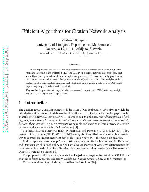
a r X i v :c s /0309023v 1 [c s .D L ] 14 S e p 2003Efficient Algorithms for Citation Network AnalysisVladimir BatageljUniversity of Ljubljana,Department of Mathematics,Jadranska 19,1111Ljubljana,Slovenia e-mail:vladimir.batagelj@uni-lj.siAbstractIn the paper very efficient,linear in number of arcs,algorithms for determining Hum-mon and Doreian’s arc weights SPLC and SPNP in citation network are proposed,and some theoretical properties of these weights are presented.The nonacyclicity problem in citation networks is discussed.An approach to identify on the basis of arc weights an im-portant small subnetwork is proposed and illustrated on the citation networks of SOM (self organizing maps)literature and US patents.Keywords:large network,acyclic,citation network,main path,CPM path,arc weight,algorithm,self organizing maps,patent1IntroductionThe citation network analysis started with the paper of Garfield et al.(1964)[10]in which the introduction of the notion of citation network is attributed to Gordon Allen.In this paper,on the example of Asimov’s history of DNA [1],it was shown that the analysis ”demonstrated a high degree of coincidence between an historian’s account of events and the citational relationship between these events ”.An early overview of possible applications of graph theory in citation network analysis was made in 1965by Garner [13].The next important step was made by Hummon and Doreian (1989)[14,15,16].They proposed three indices (NPPC,SPLC,SPNP)–weights of arcs that provide us with automatic way to identify the (most)important part of the citation network –the main path analysis.In this paper we make a step further.We show how to efficiently compute the Hummon and Doreian’s weights,so that they can be used also for analysis of very large citation networks with several thousands of vertices.Besides this some theoretical properties of the Hummon and Doreian’s weights are presented.The proposed methods are implemented in Pajek –a program,for Windows (32bit),for analysis of large networks .It is freely available,for noncommercial use,at its homepage [4].For basic notions of graph theory see Wilson and Watkins [18].Table1:Citation network characteristicsnetwork m n0k C∆in24 DNA6013700 2231218161340 Small world198816316000 105911024282320 Cocitation49293519020 308412678321052 Kroto319500116660 447023704247350 Zewail542531015166382 8843782126310984 Desalination25751141111573121 377476813764117327700Figure1:Citation Network in Standard FormLet I={(u,u):u∈U}be the identity relation on U andQ∩I=∅.The relation Q⋆=3Analysis of Citation NetworksAn approach to the analysis of citation network is to determine for each unit/arc its impor-tance or weight.These values are used afterward to determine the essential substructures in the network.In this paper we shall focus on the methods of assigning weights w:R→I R+0to arcs proposed by Hummon and Doreian[14,15]:•node pair projection count(NPPC)method:w d(u,v)=|R inv⋆(u)|·|R⋆(v)|•search path link count(SPLC)method:w l(u,v)equals the number of”all possible search paths through the network emanating from an origin node”through the arc(u,v)∈R, [14,p.50].•search path node pair(SPNP)method:w p(u,v)”accounts for all connected vertex pairs along the paths through the arc(u,v)∈R”,[14,p.51].3.1Computing NPPC weightsTo compute w d for sets of units of moderate size(up to some thousands of units)the matrix representation of R can be used and its transitive closure computed by Roy-Warshall’s algorithm [9].The quantities|R⋆(v)|and|R inv⋆(u)|can be obtained from closure matrix as row/column sums.An O(nm)algorithm for computing w d can be constructed using Breath First Search from each u∈U to determine|R inv⋆(u)|and|R⋆(v)|.Since it is of order at least O(n2)this algorithm is not suitable for larger networks(several ten thousands of vertices).3.2Search path count methodTo compute the SPLC and SPNP weights we introduce a related search path count(SPC) method for which the weights N(u,v),uRv count the number of different paths from s to t (or from Min R to Max R)through the arc(u,v).To compute N(u,v)we introduce two auxiliary quantities:let N−(v)denotes the number of different s-v paths,and N+(v)denotes the number of different v-t paths.Every s-t pathπcontaining the arc(u,v)∈R can be uniquely expressed in the formπ=σ◦(u,v)◦τwhereσis a s-u path andτis a v-t path.Since every pair(σ,τ)of s-u/v-t paths gives a corresponding s-t path it follows:N(u,v)=N−(u)·N+(v),(u,v)∈RwhereN−(u)= 1u=sv:vRu N−(v)otherwiseandN+(u)= 1u=tv:uRv N+(v)otherwiseThis is the basis of an efficient algorithm for computing the weights N(u,v)–after the topo-logical sort of the network[9]we can compute,using the above relations in topological order, the weights in time of order O(m).The topological order ensures that all the quantities in the right side expressions of the above equalities are already computed when needed.The counters N(u,v)are used as SPC weights w c(u,v)=N(u,v).3.3Computing SPLC and SPNP weightsThe description of SPLC method in[14]is not very precise.Analyzing the table of SPLC weights from[14,p.50]we see that we have to consider each vertex as an origin of search paths.This is equivalent to apply the SPC method on the extended network N l=(U′,R l)R l:=R′∪{s}×(U\∪R(s))It seems that there are some errors in the table of SPNP weights in[14,p.51].Using the definition of the SPNP weights we can again reduce their computation to SPC method applied on the extended network N p=(U′,R p)R p:=R∪{s}×U∪U×{t}∪{(t,s)}in which every unit u∈U is additionaly linked from the source s and to the sink t.3.4Computing the numbers of paths of length kWe could use also a direct approach to determine the weights w p.Let L−(u)be the number of different paths terminating in u and L+(u)the number of different paths originating in u.Then for uRv it holds w p(u,v)=L−(u)·L+(v).The procedure to determine L−(u)and L+(u)can be compactly described using two fami-lies of polynomial generating functionsP−(u;x)=h(u)k=0p−(u,k)x k and P+(u;x)=h−(u)k=0p+(u,k)x k,u∈Uwhere h(u)is the depth of vertex u in network(U,R),and h−(u)is the depth of vertex u in network(U,R inv),The coefficient p−(u,k)counts the number of paths of length k to u,and p+(u,k)counts the number of paths of length k from u.Again,by the basic principles of combinatoricsP−(u;x)= 0u=s1+x· v:vRu P−(v;x)otherwiseandP+(u;x)= 0u=t1+x· v:uRv P+(v;x)otherwiseand both families can be determined using the definitions and computing the polynomials in the(reverse for P+)topological ordering of U.The complexity of this procedure is at most O(hm).FinallyL−(u)=P−(u;1)and L+(v)=P+(v;1)In real life citation networks the depth h is relatively small as can be seen from the Table 1.The complexity of this approach is higher than the complexity of the method proposed in subsection 3.3–but we get more detailed information about paths.May be it would make sense to consider ’aging’of references by L −(u )=P −(u ;α),for selected α,0<α≤1.3.5Vertex weightsThe quantities used to compute the arc weights w can be used also to define the corresponding vertex weights tt d (u )=|R inv ⋆(u )|·|R ⋆(u )|t c (u )=N −(u )·N +(u )t l (u )=N ′−(u )·N ′+(u )t p (u )=L −(u )·L +(u )They are counting the number of paths of selected type through the vertex u .3.6Implementation detailsIn our first implementation of the SPNP method the values of L −(u )and L +(u )for some large networks (Zewail and Lederberg)exceeded the range of Delphi’s LargeInt (20decimal places).We decided to use the Extended real numbers (range =3.6×10−4951..1.1×104932,19-20significant digits)for counters.This range is safe also for very large citation networks.To see this,let us denote N ∗(k )=max u :h (u )=k N −(u ).Note that h (s )=0and uRv ⇒h (u )<h (v ).Let u ∗∈U be a unit on which the maximum is attained N ∗(k )=N −(u ∗).ThenN ∗(k )=v :vRu ∗N −(v )≤v :vRu ∗N ∗(h (v ))≤v :vRu ∗N ∗(k −1)==deg in (u ∗)·N ∗(k −1)≤∆in (k )·N ∗(k −1)where ∆in (k )is the maximal input degree at depth k .Therefore N ∗(h )≤ hk =1∆in (k )≤∆h in .A similar inequality holds also for N +(u ).From both it followsN (u,v )≤∆h (u )in ·∆h −(v )out≤∆H −1where H =h (t )and ∆=max(∆in ,∆out ).Therefore for H ≤1000and ∆≤10000we getN (u,v )≤∆H −1≤104000which is still in the range of Extended reals.Note also that in the derivation of this inequality we were very generous –in real-life networks N (u,v )will be much smaller than ∆H −1.Very large/small numbers that result as weights in large networks are not easy to use.One possibility to overcome this problem is to use the logarithms of the obtained weights –logarith-mic transformation is monotone and therefore preserve the ordering of weights (importance of vertices and arcs).The transformed values are also more convenient for visualization with line thickness of arcs.4Properties of weights4.1General properties of weightsDirectly from the definitions of weights we getw k(u,v;R)=w k(v,u;R inv),k=d,c,pandw c(u,v)≤w l(u,v)≤w p(u,v)Let N A=(U A,R A)and N B=(U B,R B),U A∩U B=∅be two citation networks,andN1=(U′A,R′A)and N2=((U A∪U B)′,(R A∪R B)′)the corresponding standardized networks of thefirst network and of the union of both networks.Then it holds for all u,v∈U A and for all p,q∈R At(1)k(u)t(2)k(v),andw(1)k(p)w(2)k(q),k=d,c,l,pwhere t(1)and w(1)is a weight on network N1,and t(2)and w(2)is a weight on network N2.This means that adding or removing components in a network do not change the ratios(ordering)of the weights inside components.Let N1=(U,R1)and N2=(U,R2)be two citation networks over the same set of units U and R1⊆R2thenw k(u,v;R1)≤w k(u,v;R2),k=d,c,p4.2NPPC weightsIn an acyclic network for every arc(u,v)∈R holdR inv⋆(u)∩R⋆(v)=∅and R inv⋆(u)∪R⋆(v)⊆Utherefore|R inv⋆(u)|+|R⋆(v)|≤n and,using the inequality √2(a+b),alsow d(u,v)=|R inv⋆(u)|·|R⋆(v)|≤1Rv⇒R⋆(u)⊂R⋆(v)The weights w d are larger in the’middle’of the network.A more uniform(but less sensitive)weight would be w s(u,v)=|R inv⋆(u)|+|R⋆(v)|or in the normalized form w′s(u,v)=14.3SPC weightsFor theflow N(u,v)the Kirchoff’s node law holds:For every node v in a citation network in standard form it holdsincomingflow=outgoingflow=t c(v)Proof:N(x,v)= x:xRv N−(x)·N+(v)=( x:xRv N−(x))·N+(v)=N−(v)·N+(v) x:xRvN(v,y)= y:vRy N−(v)·N+(y)=N−(v)· y:vRy N+(y)=N−(v)·N+(v) y:vRy2 From the Kirchoff’s node law it follows that the totalflow through the citation network equals N(t,s).This gives us a natural way to normalize the weightsN(u,v)w(u,v)=Figure2:Preprint transformationBut,new problems arise:What is the right value of the’aging’factor?Is there an efficient algorithm to count the restricted trails?The other possibility,since a citation network is usually almost acyclic,is to transform it into an acyclic network•by identification(shrinking)of cyclic groups(nontrivial strong components),or •by deleting some arcs,or•by transformations such as the’preprint’transformation(see Figure2)which is based on the following idea:Each paper from a strong component is duplicated with its’preprint’version.The papers inside strong component cite preprints.Large strong components in citation network are unlikely–their presence usually indicates an error in the data.An exception from this rule is the citation network of High Energy Particle Physics literature[20]from arXiv.In it different versions of the same paper are treated as a unit.This leads to large strongly connected components.The idea of preprint transformation can be used also in this case to eliminate cycles.6First Example:SOM citation networkThe purpose of this example is not the analysis of the selected citation network on SOM(self-organizing maps)literature[12,24,23],but to present typical steps and results in citation net-work analysis.We made our analysis using program Pajek.First we test the network for acyclicity.Since in the SOM network there are11nontrivial strong components of size2,see Table1,we have to transform the network into acyclic one.We decided to do this by shrinking each component into a single vertex.This operation produces some loops that should be removed.Figure3:Main path and CPM path in SOM network with SPC weights Now,we can compute the citation weights.We selected the SPC(search path count)method. It returns the following results:the network with citation weights on arcs,the main path network and the vector with vertex weights.In a citation network,a main path(sub)network is constructed starting from the source vertex and selecting at each step in the end vertex/vertices the arc(s)with the highest weight, until a sink vertex is reached.Another possibility is to apply on the network N=(U,R,w)the critical path method (CPM)from operations research.First we draw the main path network.The arc weights are represented by the thickness of arcs.To produce a nice picture of it we apply the Pajek’s macro Layers which contains a sequence of operations for determining a layered layout of an acyclic network(used also in analysis of genealogies represented by p-graphs).Some experiments with settings of different options are needed to obtain a right picture,see left part of Figure3.In its right part the CPMTable2:15Hubs and AuthoritiesRank Hub Id Authority Id1CLARK-JW-1991-V36-P1259HOPFIELD-JJ-1982-V79-P25540.063660.334273HUANG-SH-1994-V17-P212KOHONEN-T-1990-V78-P14640.057210.123985SHUBNIKOV-EI-1997-V64-P989#GARDNER-E-1988-V21-P2570.054960.093537VEMURI-V-1993-V36-P203MCELIECE-RJ-1987-V33-P4610.054090.076569BUSCEMA-M-1998-V33-P17RUMELHART-DE-1985-V9-P750.052580.0727111WELLS-DM-1998-V41-P173ANDERSON-JA-1977-V84-P4130.052330.0703313SMITH-KA-1999-V11-P15KOSKO-B-1987-V26-P49470.051490.0580215KOHONEN-T-1990-V78-P1464GROSSBERG-S-1987-V11-P23 path is presented.We see that the upper parts of both paths are identical,but they differ in the continuation. The arcs in the CPM path are thicker.We could display also the complete SOM network using essentially the same procedure as for the displaying of main path.But the obtained picture would be too complicated(too many vertices and arcs).We have to identify some simpler and important subnetworks inside it.Inspecting the distribution of values of weights on arcs(lines)we select a threshold0.007 and determine the corresponding arc-cut–delete all arcs with weights lower than selected threshold and afterwards delete also all isolated vertices(degree=0).Now,we are ready to draw the reduced network.Wefirst produce an automatic layout.We notice some small unimportant components.We preserve only the large main component,draw it and improve the obtained layout manually.To preserve the level structure we use the option that allows only the horizontal movement of vertices.Finally we label the’most important vertices’with their labels.A vertex is considered important if it is an endpoint of an arc with the weight above the selected threshold(in our case 0.05).The obtained picture of SOM’main subnetwork’is presented in Figure4.We see that the SOMfield evolved in two main branches.From CARPENTER-1987the strongest(main path) arc is leading to the right branch that after some steps disappears.The left,more vital branch is detected by the CPM path.Further investigation of this is left to the readers with additional knowledge about the SOMfield.As a complementary information we can determine Kleinberg’s hubs and authorities vertex weights[17].Papers that are cited by many other papers are called authorities;papers that cite many other documents are called hubs.Good authorities are those that are cited by good hubsFigure4:Main subnetwork at level0.007and good hubs cite good authorities.The15highest ranked hubs and authorities are presented in Table2.We see that the main authorities are located in eighties and the main hubs in nineties. Note that,since we are using the relation uRv≡u is cited by v,we have to interchange the roles of hubs and authorities produced by Pajek.An elaboration of the hubs and authorities approach to the analysis of citation networks complemented with visualization can be found in Brandes and Willhalm(2002)[8].7Second Example:US patentsThe network of US patents from1963to1999[21]is an example of very large network (3774768vertices and16522438arcs)that,using some special options in Pajek,can still be analyzed on PC with at least1G memory.The SPC weights are determined in a range of1 minute.This shows that the proposed approach can be used also for very large networks.The obtained main path and CPM path are presented in Figure5.Collecting from the United States Patent and Trademark Office[22]the basic data about the patents from both paths,see Table3-6,we see that they deal with’liquid crystal displays’.But,in this network there should be thousands of’themes’.How to identify them?Using the arc weights we can define a theme as a connected small subnetwork of size in the interval k ..K(for example,between k=1Table3:Patents on the liquid-crystal display patent author(s)and titleMar13,1951Jun29,1954May30,1967May19,1970Jan18,1972May30,1972Jul11,1972Sep19,1972Oct10,1972May8,1973Jun19,1973Oct23,1973Nov20,1973Mar5,1974Mar12,1974Apr23,1974May7,1974Mar18,1975Apr8,1975May6,1975Jun24,1975Mar30,1976May4,1976Jun1,1976Aug17,1976Dec28,1976Mar8,1977Mar22,1977Apr12,1977Table4:Patents on the liquid-crystal display patent author(s)and titleJun14,1977Jun28,1977Mar7,1978Apr4,1978Apr11,1978Sep12,1978Oct3,1978Dec19,1978Apr17,1979May15,1979Apr1,1980Apr15,1980May13,1980Oct21,1980Apr14,1981Sep22,1981Oct6,1981Nov24,1981May18,1982Jul20,1982Sep14,1982Nov2,1982Nov30,1982Jan11,1983May31,1983Jun7,1983Jun7,1983Aug23,1983Nov15,1983Dec6,1983Dec27,1983Jun19,1984Jun26,1984Jul17,1984Sep18,1984Table5:Patents on the liquid-crystal display patent author(s)and titleSep18,1984Oct30,1984Mar5,1985Apr9,1985Apr30,1985Jul2,1985Nov5,1985Dec10,1985Apr22,1986Nov11,1986Dec23,1986Apr14,1987Apr21,1987Sep22,1987Nov3,1987Nov24,1987Dec1,1987Dec15,1987Jan12,1988Jan26,1988Jun21,1988Sep13,1988Jan3,1989Jan10,1989Apr11,1989May23,1989Oct31,1989Sep18,1990May21,1991May21,1991Jun16,1992Jun23,1992Dec15,1992Dec29,1992Table6:Patents on the liquid-crystal display patent author(s)and titleSep7,1993Feb1,1994May3,1994June7,1994Dec20,1994Apr18,1995Jul23,1996Aug6,1996Sep10,1996Nov4,1997Jun23,1998Jan5,1999Nov23,1999Dec21,19992510205010011001000sizef r e qFigure 6:Island size frequency distributionTable8:Some patents from the’foam’island patent author(s)and titleNov29,1977Sep29,1981Nov2,1982Jul10,1984Jan29,1985Oct1,1985Dec22,1987May22,1990Feb26,1991Dec8,1992Feb16,1993May3,1994Sep24,1996Table9:Some patents from’fiber optics and bags’island patent author(s)and titleJul24,1984Apr16,1985Jul23,1985May20,1986Jun30,1987Jan12,1988Nov15,1988Nov22,1988Mar7,1989Mar7,1989May9,1989Jan1,1991Mar5,1991Feb23,1993May3,1994Nov15,1994The subnetworks approach onlyfilters out the structurally important subnetworks thus pro-viding a researcher with a smaller manageable structures which can be further analyzed using more sophisticated and/or substantial methods.9AcknowledgmentsThe search path count algorithm was developed during my visit in Pittsburgh in1991and pre-sented at the Network seminar[2].It was presented to the broader audience at EASST’94in Budapest[3].In1997it was included in program Pajek[4].The’preprint’transformation was developed as a part of the contribution for the Graph drawing contest2001[5].The al-gorithm for the path length counts was developed in August2002and the Islands algorithm in August2003.The author would like to thank Patrick Doreian and Norm Hummon for introducing him into thefield of citation network analysis,Eugene Garfield for making available the data on real-life networks and providing some relevant references,and Andrej Mrvar and Matjaˇz Zaverˇs nik for implementing the algorithms in Pajek.This work was supported by the Ministry of Education,Science and Sport of Slovenia, Project0512-0101.References[1]Asimov I.:The Genetic Code,New American Library,New York,1963.[2]Batagelj V.:Some Mathematics of Network work Seminar,Department ofSociology,University of Pittsburgh,January21,1991.[3]Batagelj V.:An Efficient Algorithm for Citation Networks Analysis.Paper presented atEASST’94,Budapest,Hungary,August28-31,1994.[4]Batagelj V.,Mrvar A.:Pajek–program for analysis and visualization of large networks.http://vlado.fmf.uni-lj.si/pub/networks/pajek/http://vlado.fmf.uni-lj.si/pub/networks/pajek/howto/extreme.htm [5]Batagelj V.,Mrvar A.:Graph Drawing Contest2001Layoutshttp://vlado.fmf.uni-lj.si/pub/GD/GD01.htm[6]Batagelj V.,Zaverˇs nik M.:Generalized Cores.Submitted,2002./abs/cs.DS/0202039[7]Batagelj V.,Zaverˇs nik M.:Islands–identifying themes in large networks.In preparation,August2003.[8]Brandes U.,Willhalm T.:Visualization of bibliographic networks with a reshaped land-scape metaphor.Joint Eurographics–IEEE TCVG Symposium on Visualization,D.Ebert, P.Brunet,I.Navazo(Editors),2002.http://algo.fmi.uni-passau.de/˜brandes/publications/bw-vbnrl-02.pdf[9]Cormen T.H.,Leiserson C.E.,Rivest R.L.,Stein C.:Introduction to Algorithms,SecondEdition.MIT Press,2001.[10]Garfield E,Sher IH,and Torpie RJ.:The Use of Citation Data in Writing the History ofScience.Philadelphia:The Institute for Scientific Information,December1964./papers/useofcitdatawritinghistofsci.pdf[11]Garfield E.:From Computational Linguistics to Algorithmic Historiography,paper pre-sented at the Symposium in Honor of Casimir Borkowski at the University of Pittsburgh School of Information Sciences,September19,2001./papers/pittsburgh92001.pdf [12]Garfield E.,Pudovkin A.I.,Istomin,V.S.:Histcomp–(comp iled Hist oriography program)/histcomp/guide.html/histcomp/index.html[13]Garner R.:A computer oriented,graph theoretic analysis of citation index structures.Flood B.(Editor),Three Drexel information science studies,Philadelphia:Drexel Univer-sity Press1967./rgarner.pdf[14]Hummon N.P.,Doreian P.:Connectivity in a Citation Network:The Development of DNATheory.Social Networks,11(1989)39-63.[15]Hummon N.P.,Doreian P.:Computational Methods for Social Network Analysis.SocialNetworks,12(1990)273-288.[16]Hummon N.P.,Doreian P.,Freeman L.C.:Analyzing the Structure of the Centrality-Productivity Literature Created Between1948and1979.Knowledge:Creation,Diffusion, Utilization,11(1990)4,459-480.[17]Kleinberg J.:Authoritative sources in a hyperlinked environment.In Proc9th ACMSIAMSymposium on Discrete Algorithms,1998,p.668-677./home/kleinber/auth.ps/kleinberg97authoritative.html[18]Wilson,R.J.,Watkins,J.J.:Graphs:An Introductory Approach.New York:John Wileyand Sons,1990.[19]Pajek’s datasets–citation networks:http://vlado.fmf.uni-lj.si/pub/networks/data/cite/[20]KDD Cup2003:/projects/kddcup/index.html/[21]Hall,B.H.,Jaffe,A.B.and Tratjenberg M.:The NBER U.S.Patent Citations Data File.NBER Working Paper8498(2001)./patents/[22]The United States Patent and Trademark Office./netahtml/srchnum.htm[23]Bibliography on the Self-Organizing Map(SOM)and Learning Vector Quantization(LVQ)a.de/bibliography/Neural/SOM.LVQ.html[24]Neural Networks Research Centre:Bibliography of SOM papers.http://www.cis.hut.fi/research/refs/。
- 1、下载文档前请自行甄别文档内容的完整性,平台不提供额外的编辑、内容补充、找答案等附加服务。
- 2、"仅部分预览"的文档,不可在线预览部分如存在完整性等问题,可反馈申请退款(可完整预览的文档不适用该条件!)。
- 3、如文档侵犯您的权益,请联系客服反馈,我们会尽快为您处理(人工客服工作时间:9:00-18:30)。
He married Anne Isabella Milbanke in 1815, Byron left England in 1816, never to return. He settled in Geneva with Percy Bysshe Shelley, Mary Shelley, and Claire Clairmont, who became his mistress.
George Gordon Byron:
(1788-1824) his personality cult &his poetry.
ⅠPersonal Background1
birth: he was born with a club-foot; 6-10: started his education----The Grammar school lay him good foundation 8-9:strengthened his muscles at a farmhouse--the grandeur of the Scottish scenery; 10: the death of his great uncle; himself as the 6th Baron—he title and the estate after the possesstion of the title: received treatment and maltreatment from a quack at Nottingham. At his own request he read Virgil and Cicero with a tutor.
“an epic satire” (p 233)
The homework: option 1 Read Isles of Greece Select your favorite lines and explain why Due time: first week in May
纽约的拜伦公园拜伦像
Don Juan
16 cantos written in ottava rima (八行诗) each stanza containing 8 lines, rhymed ab ab ab cc (with end rhymes to build up force) characters: Don Juan the hero, Haidee, a pirate's daughter
ⅠPersonal Background2
On the 13th of March 1809, he took his seat in
the House of Lords 16: fell in love, once for all, with his distant relative, Mary Anne Chaworth Byron went into residence at Trinity College, Cambridge, after graduating from Harrow. Cambridge did him no good. "The place is the devil, “where he piled up debts and aroused alarm with bisexual love affairs.
His Masterpieces (p 225)
Childe Harold’s Pilgrimage Don Juan
Байду номын сангаас
Childe Harold’s Pilgrimage
written in Spenserian stanza: a 9-line stanza rhymed abab bcbc c in which the first 8 lines are in iambic pentameter while the ninth in iambic hexameter. his love for liberty his hatred for oppression
. He armed a brig, the Hercules, and sailed to Greece to aid the Greeks, who had risen against their Ottoman overlords. , Byron contracted a fever from which he died on 19 April 1824. . Byron's body was returned to England but refused by the deans of both Westminster and St Paul's. Finally Byron's coffin was placed in the family vault