am335x_linux-3.14.43内核移植笔记
AM335x学习记录

AM335x 学习笔记1 硬件及其开发环境篇1.1 开发环境的搭建1.1.1 路由器方式的 NFS 启动1) 通过路由器的方式来启动 NFS 文件系统 设置路由器局域网的网关:192.168.1.1,然后将开发板和 PC 都连接在路由器的 LAN 端口,并且采用 DCHP 的 方式来实现 tftp 和 nfs。
2) uEnv.txtserverip=192.168.1.27 rootpath=/opt/ti-sdk-am335x-evm/targetNFS bootfile=uImage-am335x-evm.bin ip_method=dhcp tftp_nfs_boot=echo Booting from network...; dhcp ${loadaddr} ${bootfile}; run net_args; bootm ${loadaddr} uenvcmd=run tftp_nfs_boot1.1.2 Root 用户登陆#sudo passwd root #****** #****** #sudo –s –H 切换到 root 用户 然后就可以重启虚拟机,以用户 root 来登陆1.1.3 中文字库问题#locale –a 查看 是否有 zh_CN,zh_CN.gb18030,zh_CN.gb2312 等 #vim /var/lib/locales/supported.d/local#dpkg-reconfigure locales #locale-gen zh_CN.GB18030 #locale-gen zh_CN.GB2312 #locale-gen zh_CN.GBK1.1.4 环境变量设置路径#vim /etc/envinoment 常用的 3 个永久设置路径 #vim /etc/envirnoment #vim /etc/profile #vim ~/.bashrc (/root/.bashrc)1.1.5 设置 ubuntu 的上网 ip设置为 bridge 连接方式,设定静态 IP 地址.1.1.6 更改 sh 工具#rm /bin/sh # ln –s /bin/bash /bin/sh #apt-get install fakeroot1.1.7 安装必须的工具#apt-get install vim #apt-get install build-essential #apt-get install libtool #apt-get install bsion(干什么用的还不清楚) GNU autotools 主要包括三个工具 autoconf, automake,libtool1.1.8 虚拟机开发工具的安装$ sudo apt-get install build-essential libncurses-dev flex bison autoconf automake libmpfr-dev texinfo nfs-kernel-server tftpd-hpa libcloog-ppl1.2 AM335x BeagleBone 的 NFS 启动Sd 卡的识别:在/media/下面显示内容 在/dev/sd* 下显示分区 卸载:#unmount /dev/sdb1 这个是在 AM335X-LINUX-PSP-04.06.00.03 里面找的 1) 制作 sd 启动盘 MLO+uboot.img+uImage+rootfs#!/bin/bash if [[ -z $1 || -z $2 || -z $3 || -z $4 ]] then echo "mksd-am335x Usage:" echo " echo " exit fi if ! [[ -e $2 ]] then echo "Incorrect MLO location!" exit fi if ! [[ -e $3 ]] then echo "Incorrect u-boot.img location!" exit fi if ! [[ -e $4 ]] then echo "Incorrect uImage location!" exit fi if ! [[ -e $5 ]] then echo "Incorrect rootfs location!" exit fi echo "All data on "$1" now will be destroyed! Continue? [y/n]" read ans if ! [ $ans == 'y' ] then exit fi echo "[Partitioning $1...]" DRIVE=$1 dd if=/dev/zero of=$DRIVE bs=1024 count=1024 SIZE=`fdisk -l $DRIVE | grep Disk | awk '{print $5}'` echo DISK SIZE - $SIZE bytes CYLINDERS=`echo $SIZE/255/63/512 | bc` echo CYLINDERS - $CYLINDERS mksd-am335x <device> <MLO> <u-boot.img> <uImage> <rootfs tar.gz >" Example: mksd-am335x /dev/sdc MLO u-boot.img uImage nfs.tar.gz"{ echo ,9,0x0C,* echo ,,,} | sfdisk -D -H 255 -S 63 -C $CYLINDERS $DRIVE echo "[Making filesystems...]" mkfs.vfat -F 32 -n boot "$1"1 &> /dev/null mkfs.ext3 -L rootfs "$1"2 &> /dev/null echo "[Copying files...]" mount "$1"1 /mnt cp $2 /mnt/MLO cp $3 /mnt/u-boot.img cp $4 /mnt/uImage umount "$1"1 mount "$1"2 /mnt tar zxvf $5 -C /mnt &> /dev/null chmod 755 /mnt umount "$1"2 echo "[Done]"2) 建立 uEnv.txt (我是将 tf 卡放入读卡器,在虚拟机下面 vim 编写的。
AM335x 处理器 SDK RTOS 板库端口和启动说明书

Board Porting\Bring up using Processor SDK RTOS for AM335xProcessor SDK RTOS component known as board library consolidates all the board-specific information so that all the modifications made when moving to a new custom platform using the SOC can be made in the source of this library.There are three different components in PRSDK that help in porting and bring up of a custom board:∙Board library updatesa.PLL Clocking and PRCMb.Pin mux Updatec.DDR Configurationd.Peripheral instances updates∙Diagnostics tests∙Boot loader updatesBoard Library Updates in Processor SDK RTOS:PLL ClockingThere are two places where the device PLL configurations are performed when using Processor SDK RTOS and CCS.Debug environment:Debug environment refers to development setup where code is debugged using JTAG emulator on the SOC. The PRSDK software relies on the GEL file that is part of the target configuration to setup the clocks and the DDR for the device. The CCS GEL file for AM335x platforms is located in the CCS package at the location ccsv7\ccs_base\emulation\boards\<boardName>For example for beagle bone black, the files can be found atccsv7\ccs_base\emulation\boards\beaglebone\gelThe GEL is the first piece of software that should be brought up on a custom board.Production environment:Production environment refers to the setup when the base application is booted from a boot media like a flash memory or host interface. In this environment, the bootloader sets performs all the SOC and board initialization and copies the application from flash memory to the device memory.The clock setup in the bootloader code can be located atpdk_am335x_x_x_x\packages\ti\starterware\bootloader\src\am335xUsers can choose to use the platform clocking similar to one of TI reference platforms or can modify them as per their application requirements. By default the PLL settings are setup for OPP_NOM settings (MPU= 600 MHz.)TI provides Clock Tree tool to allow users to simulate the clocking on the SOC. For quick reference of the multiplier and divider settings to change the PLL setting is provided in the spreadsheetAM335x_DPLL_CALCv3.xlsx.After modifying the clocking in the bootloader, users need to rebuild the bootloader using instructions provided in Processor_SDK_RTOS_BOOT_AM335x/AM437xPRCM Modules Enable:PRCM Module Enable is required to turn on the power domain and the clocking to each of the modules on the SOC. The PRCM Enable calls to enable each module are made from the functionBoard_moduleClockInit which is found in the location.pdk_am335x_1_0_9\packages\ti\board\src\bbbAM335x\bbbAM335x.cCheck every instance and peripheral required in the application platform and enable the module in the board library.For example to use three UARTs 0, 1 and 4, ensure that you have the following code as part of the board library setup:/* UART */status = PRCMModuleEnable(CHIPDB_MOD_ID_UART, 0U, 0U);status = PRCMModuleEnable(CHIPDB_MOD_ID_UART, 1U, 0U);status = PRCMModuleEnable(CHIPDB_MOD_ID_UART, 4U, 0U);Note: PRCMEnable function is defined in pdk_am335x_1_0_9\packages\ti\starterware\soc\am335x Pinmux updates in the Board library:Generating a New PinMux Configuration Using the PinMux Utility: This procedure uses the cloud-based pinmux utilityNavigate to ${PDK_INSTALL_DIR}\packages\ti\starterware\tools\pinmux_config\am335x and Load beaglebone_black_configAdd and remove peripheral instances and select the appropriate use cases required for development based on the application platform requirements and resolve all conflicts.Refer Pin_Mux_Utility_for_ARM_MPU_ProcessorsPost Processing steps:1.Change the Category filter to starterware and download the pinmux files am335x_pimnmux.hand am335x_pinmux_data.c2.At the bottom of am335x_pinmux.h change extern pinmuxBoardCfg_t gAM335xPinmuxData[];to extern pinmuxBoardCfg_t gBbbPinmuxData[];3.Change am335x_pinmux_data.c to am335x_beagleboneblack_pinmux_data.c.4.Change gAM335xPinmuxData to gBbbPinmuxData at the end of the file in file5.am335x_beagleboneblack_pinmux_data.c.Replace the existing files with the new files and rebuild the board library using the instructions in the section Rebuilding board Library in Processor SDK RTOS:Updating DDR settings:Similar to clock and PLL settings, DDR initialization is configured in the Debug environment through GEL files and in production environment using bootloader source files.TI provides AM335x_EMIF_Configuration_tips which contains a spreadsheet to enter the timing from the DDR datasheet to compute the EMIF timing number required to initialize DDR.We strongly recommend changing the value and testing using GEL files before using them in the bootloader software. For Sanity test, you can perform read/write tests using CCS Memory Browser or run the diagnostic memory read/write test that we provide in diagnostics package here:PDK_INSTALL_PATH\packages\ti\board\diag\memOnce the DDR timings have been confirmed, you can use the settings in the file:PDK_INSTALL_PATH \packages\ti\starterware\bootloader\src\am335x\sbl_am335x_platform_ddr.c Peripheral initialization:The board library is responsible for most of the SOC initialization but it also setup some board level components such as ethernet PHY and debug UART and I2C for reading board ID from EEPROM. All of the other peripheral instances and initialization needs to be done from the application level.For example for beagleboneblack, the peripheral initialization are performed from the source filepdk_am335x_1_0_9\packages\ti\board\src\bbbAM335x\bbbAM335x_lld_init.cThe debug UART instance, I2C Addresses are set using the file board_cfg.h found under:pdk_am335x_1_0_9\packages\ti\board\src\bbbAM335x\includeDefault UART instance is set to 0 in the board library. The Board initialization will configure the UART instance 0 to send binary log data to serial console using the Board_UARTInit function. If you wish to use more UART instances then we recommend linking in the UART driver in the application and using UART_open() and UART_stdioInit API calls from the application.Each peripheral driver in the Processor SDK RTOS has a SOC configuration that provides the interrupt numbers, base address, EDMA channels which can be updated using the file <peripheral>_soc.c file. This is used as default setup for initializing the driver instance. It can be overridden from the application using peripheral_getSOCInitCfg() and peripheral_setSOCInitCfg()For Example: All instances of UART for AM335x have been mapped in the filepdk_am335x_1_0_9\packages\ti\drv\uart\soc\am335x\UART_soc.cSystem integrators need to ensure that no interrupt numbers and EDMA resource conflicts exist in the SOC configuration for all drivers used in the system.To exercise three UARTs in the system, users can use the following code://Setup Debug UARTboardCfg = BOARD_INIT_PINMUX_CONFIG |BOARD_INIT_MODULE_CLOCK |BOARD_INIT_UART_STDIO;Board_init(boardCfg);// Open Additional UART Instances:/* UART SoC init configuration */UART_initConfig(false);/* Initialize the default configuration params. */UART_Params_init(&uartParams);// Open UART Instance 1uartTestInstance =1;uart1 = UART_open(uartTestInstance, &uartParams);//Open UART Instance 4uartTestInstance = 4;uart4 = UART_open(uartTestInstance, &uartParams);BoardID Detect:TI supports multiple evaluation and reference platforms for AM335x hence the hardware platforms are populated with an EEPROM which contains information that identifies the hardware and its revision. The board library and software components read the boardID and initialize the platform based on the boardID. The BoardID_detect function can be found in the source in the file bbbAM335x_info.c in the board library and board_am335x.c in the bootloader source at:<PDK_INSTALL_PATH>\packages\ti\starterware\board\am335xRebuilding board Library in Processor SDK RTOS:While Creating a new folder for the custom board is an option users can explore, TI recommends that users make there changes in existing board package using either bbbAM335x, evmAM335x oriceAM335x folder to avoid spending additional effort to modify the build files for including the customBord.Once all the update to the board library are completed, the board library can be updated using the following instructions.Instructions to rebuild board library:Setup Processor SDK build environment before following steps provided below.cd pdk_am335x_1_0_9\packagesgmake board_libFor a specific board users are required to provide the LIMIT_BOARDS argument.LIMIT_BOARDS : evmAM335x icev2AM335x iceAMIC110 bbbAM335x skAM335xFor Example for beagleboneblack, users can use the following build option:gmake board_lib LIMIT_BOARDS=bbbAM335xDiagnostics:After the board library is built, we highly recommend that you create a diagnostics package similar to one provided in board library to test different interfaces functionally during board bring up.The diagnostics package can be located at pdk_am335x_1_0_9\packages\ti\board\diag. These are simple bare-metal tests that use peripheral drivers to help functionally validate the pins and interfaces.Documentation for all available diagnostic tests is provided here:/index.php/Processor_SDK_RTOS_DIAGBootloader in Processor SDK RTOS:As part of the production flow, users are required to develop/port flashing and booting utilities so the application can be launched on the custom board with JTAG. TI provides a bootloader mechanism where the ROM bootloader loads a secondary bootloader on the onchip memory that initializes the SOC and DDR and then copies the application into DDR memory.The boot process and flashing tools have been described in detail in the following article that is part of processor SDK RTOS Software developer`s guide:/index.php/Processor_SDK_RTOS_BOOT_AM335x/AM437x#Building_the_B ootloader。
Linux内核移植手册
图1-1 内核配置选项主菜单
上图显示的是一个主菜单,主菜单中还包含了很多子菜单,通过敲键盘的↑、↓键可以选择不同的子菜单,再敲回车键,进入这些子菜单,可以看到该子菜单下的一些功能选项,如我们进入System Type这个子菜单,便可以看到如图1-2 所示的界面:
[root@BC linux-2.6.24.4]# make menuconfig
图2-6-1 内核配置界面
smdk2410_defconfig基础上,增删以下内核配置项:在配置菜单中,选择system type-->s3c2410 machines中的smdk2410,其他的arch-machines全部取消。
图2-6-2 内核配置选项(1)
图2-6-3 内核配置选项(2)
至于所有其他的选项都默认s3c2410_defconfig 给定的配置,这里暂时不做修改。
在后续实验中,需要添加相应的功能时再对相关选项重新进行配置。
重新保存为.config并退出。
图2-6-5 保存内核配置选项(2)
extern struct platform_device s3c_device_ts;
}。
EM335x Linux 内核用户烧写说明 - 工控主板,嵌入式主板,嵌入
EM335x Linux内核用户烧写说明EM335x内核的烧写不使用任何烧写工具软件,利用SD卡启动来实现自动烧写,将需要烧写的内核文件均复制到sd卡上即可。
EM335x的启动顺序首先选择NandFlash,第二选择SD卡启动,第三选择串口启动。
所以在重新烧制EM335x内核文件时需要两个步骤,一个完全擦除NandFlash;一个是制作SD卡。
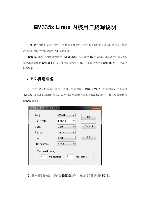
一、PC机端准备1、作为PC机端需要运行一个串口终端程序:Tera Term VT终端程序,用于监测EM335x调试串口输出的信息,以及通过终端程序操作EM335x板卡,串口配置参数为115200-8-n-1。
2、用户需要将光盘中提供的EM335x所有内核烧写文件复制到PC上。
二、擦除NandFlash说明NandFlash的擦除利用uboot命令中nand相关命令来实现进行1、板卡正常启动在EM335x可以正常启动的状态下,将板卡置于调试模式,利用uboot擦除全擦除。
按“空格”键进入uboot菜单状态,执行以下命令。
#>nand erase.chip2、板卡出现异常,无法正常执行启动代码。
先用镊子短接EM335x板上的JP1,超级终端会不断提示“CCCCC”,此时在Tera Term VT终端程序下,选择File->Transfer->XMODEM->send,选择u-boot-spl.bin 文件正常执行的话应该显示下载文件的进度条,显示下载过程正常后,立即松开短接的镊子。
该文件下载完成后,再选择File->Transfer->YMODEM->send ,选择u-boot.img待该文件下载完成后,EM335x则可自动启动。
启动到uboot时,再按“空格”键进入uboot菜单状态。
#>nand erase.chip三、micro SD卡启动制作制作SD卡会用到EM335x内核文件夹目录下文件包括:1) MLO2) u-boot.img3) emcfg.txt ( 注:该文件需要用户根据屏的分辨率进行配置)4) MLO15) u-boot1.img6) splash800480.bmp ( 注:该文件为emcfg.txt所指定的启动画面文件)7) am335x-em335x.dtb8) zImage9) ubifs-qt.img对用户来讲,emcfg.txt主要是用于配置需要烧写的启动画面文件名,以及dtb 、kernel内核文件、ubi文件系统等文件名,通过该文件来适应不同分辨率的LCD屏。
飞凌AM335x开发板Linux用户手册

飞凌AM335x开发板Linux用户手册OK335X-Linux用户手册第一章OK335X简介OK335X开发板基于TI AM335X处理器,运行主频最高720M,支持Linux,WinCE,Android三大操作系统,可用于工业产品设计。
OK335X有核心板和底板组成,核心板主要芯片有:CPU,NandFlash,Memory,PowerManage。
使用我们的核心板,只需要根据您的业务需求开发自己的底板,这样可加速您的产品上市时间,让您从平台搭建的复杂环境中脱离。
下面我们具体描述OK335X核心板和底板资源。
OK335X产品图片如下所示:核心板硬件资源:1CPU主频:720M(支持AM3352,AM3354,AM3356,AM3357,AM3358,AM3359)2NandFlash:256M(Micro SLC)3Memory:265M(Micro DDR2)4PowerManage IC:TPS65217B(TI AM335X专用电源IC)底板资源:14路串口(2个232电平,2个TTL电平,232电平已经使用DB9座子引出,其中COM0作为调试串口使用,注意:OK335X-V1底板中UART4暂时不能使用,下一硬件版本将修正这个问题)。
21路100M网口3音频接口(1路Phone输出,1路Line-in输入)41个SD卡接口56个用户按键63路I2C接口71个LCD接口(支持RGB888模式,支持电阻触摸和电容触摸。
默认标配7寸电阻屏)81路PWM接口,用于蜂鸣器测试。
91路Can接口101路SDIO接口11多路用户IO接口12四路USB2.0接口,一路USB2.0OTG(目前板子为一路USB Host接口,后续会增加到四路USB HUB)131路SPI接口148路AD(其中4路用于电阻触摸,1路用于滑动变阻器AD测试,其余3路通过插针引出,另外滑动变阻器端有跳线设置,通过跳线可以设置这路AD用于插针引出,还是用于可调电阻测试)15引出总线接口(缺省未焊接底座)161个RESET按钮,用于系统复位。
MYD-AM335X-J Linux 开发手册说明书

MYD-AM335X-J Linux 开发手册版本V1.12014/10/23版本记录目录第1章概述及软件资源介绍 (1)1.1 概述 (1)1.2 软件资源 (1)第2章Linux开发环境搭建 (3)2.1 建立工作目录 (3)2.2 设置交叉编译工具 (3)2.3 安装工具 (3)第3章Linux系统编译 (4)3.1 编译Bootloader (4)3.2 编译Linux内核 (5)3.3 制作文件系统 (5)第4章Linux 系统烧写 (6)4.1 TF卡系统映像更新 (6)4.2 NAND Flash更新/恢复 (7)第5章Linux应用程序 (10)5.1 GPIO (10)5.2 NET (10)5.3 RTC (11)5.4 LCD (11)5.5 Audio (12)5.6 I2C总线测试 (12)5.7 串口 (12)5.8 RS485 (12)5.9 CAN (13)5.10 引脚功能切换 (13)5.10.1 RS485_1跟UART5_RTSCTS 切换145.10.2 RS485_2和UART3切换及CAN1和UART4切换15第6章Qt开发 (17)6.1 使用光盘提供的Qt SDK (17)6.2 交叉编译Qt开发环境 (17)6.3 移植Qt到开发板 (18)6.4 交叉编译Qt应用程序 (19)第1章概述及软件资源介绍1.1 概述MYD-AM335X-J提供了丰富的系统资源和软件资源,本手册将从环境搭建开始,一步步介绍如何进行MYD-AM335X-J Linux开发。
本手册中开发主机上的命令以Ubuntu为例进行教授。
1.2 软件资源表1-1第2章Linux开发环境搭建2.1 建立工作目录拷贝MYD-AM335X-J光盘中的资料到主机中:$ mkdir -p <WORKDIR>$ cp -a <DVDROM>/05-Linux_Source/* <WORKDIR>2.2 设置交叉编译工具$ cd <WORKDIR>/Toolchain$ tar -xvjf \gcc-linaro-arm-linux-gnueabihf-4.7-2013.03-20130313_linux.tar.bz2$ export PATH=$PATH:<WORKDIR>/Toolchain/\gcc-linaro-arm-linux-gnueabihf-4.7-2013.03-20130313_linux/bin$ export CROSS_COMPILE=arm-linux-gnueabihf-执行完“export”命令后输入arm按Tab键来检查是否设置成功,该设置只对当前终端有效,如需永久修改,请修改用户配置文件。
飞凌AM335x开发板Linux用户手册
OK335X-Linux用户手册第一章OK335X简介OK335X开发板基于TI AM335X处理器,运行主频最高720M,支持Linux,WinCE,Android三大操作系统,可用于工业产品设计。
OK335X有核心板和底板组成,核心板主要芯片有:CPU,NandFlash,Memory,PowerManage。
使用我们的核心板,只需要根据您的业务需求开发自己的底板,这样可加速您的产品上市时间,让您从平台搭建的复杂环境中脱离。
下面我们具体描述OK335X核心板和底板资源。
OK335X产品图片如下所示:核心板硬件资源:1CPU主频:720M(支持AM3352,AM3354,AM3356,AM3357,AM3358,AM3359)2NandFlash:256M(Micro SLC)3Memory:265M(Micro DDR2)4PowerManage IC:TPS65217B(TI AM335X专用电源IC)底板资源:14路串口(2个232电平,2个TTL电平,232电平已经使用DB9座子引出,其中COM0作为调试串口使用,注意:OK335X-V1底板中UART4暂时不能使用,下一硬件版本将修正这个问题)。
21路100M网口3音频接口(1路Phone输出,1路Line-in输入)41个SD卡接口56个用户按键63路I2C接口71个LCD接口(支持RGB888模式,支持电阻触摸和电容触摸。
默认标配7寸电阻屏)81路PWM接口,用于蜂鸣器测试。
91路Can接口101路SDIO接口11多路用户IO接口12四路USB2.0接口,一路USB2.0OTG(目前板子为一路USB Host接口,后续会增加到四路USB HUB)131路SPI接口148路AD(其中4路用于电阻触摸,1路用于滑动变阻器AD测试,其余3路通过插针引出,另外滑动变阻器端有跳线设置,通过跳线可以设置这路AD用于插针引出,还是用于可调电阻测试)15引出总线接口(缺省未焊接底座)161个RESET按钮,用于系统复位。
am335x_linux-3.14.43内核移植笔记
本文主要描述在EVB335X-II以Device Tree的方式移植新TI官网AM335X系列最新的linux-3.14.43版本内核以及移植Debian文件系统的过程及遇到的一些问题。
整个Device Tree牵涉面比较广,即增加了新的用于描述设备硬件信息的文本格式(即.dts文件),又增加了编译这一文本的工具,同时Bootloader也需要支持将编译后的Device Tree传递给Linux内核。
以下是修改步骤:一、修改uboot,支持Device TreeEVB335X-II在linux-3.2版本内核移植的时候已经有uboot,因此只需在该uboot上增加Device Tree支持即可,以下是修改步骤:1、修改include/configs/com335x.h文件,增加支持DT的宏定义:/* Flattened Device Tree */#define CONFIG_OF_LIBFDT2、修改uboot启动参数,增加dtb文件的加载和启动(由于目前只是移植EMMC版本的EVB335X-II,因此只需修改EMMC的启动参数即可,大概在405行),修改如下:#elif defined(CONFIG_EMMC_BOOT)#define CONFIG_BOOTCOMMAND \"run mmcboot;"#define CONFIG_EXTRA_ENV_SETTINGS \"lcdtype=AUO_AT070TN94\0" \"console=ttyO0,115200n8\0" \"mmcroot=/dev/mmcblk0p2 rw\0" \"mmcrootfstype=ext4 rootwait\0" \"mmcargs=setenv bootargs console=${console} noinitrd root=${mmcroot} rootfstype=${mmcrootfstype} lcdtype=${lcdtype} consoleblank=0\0" \"mmcdev=" MMCDEV "\0" \"loadaddr=0x81000000\0" \"dtbfile=evb335x-ii-emmc.dtb\0" \"bootenv=uEnv.txt\0" \"bootpart=" BOOTPART "\0" \"loadbootenv=load mmc ${mmcdev} ${loadaddr} ${bootenv}\0" \"importbootenv=echo Importing environment from mmc ...; " \"env import -t $loadaddr ${filesize}\0" \"loadaddr-dtb=0x82000000\0" \"loadimage=load mmc ${bootpart} ${loadaddr} uImage\0" \"loaddtb=load mmc ${bootpart} ${loadaddr-dtb} ${dtbfile}\0" \"mmcboot=mmc dev ${mmcdev}; " \"if mmc rescan; then " \"echo SD/MMC found on device ${mmcdev};" \"if run loadbootenv; then " \"echo Loaded environment from ${bootenv};" \"run importbootenv;" \"fi;" \"run mmcargs;" \"if run loadimage; then " \"run loaddtb;" \"bootm ${loadaddr} - ${loadaddr-dtb};" \"fi;" \"fi; \0"#endif以上,红色为修改部分。
AM335x的linux内核移植
摘要随着时代的发展,人们的生活越来越离不开电子产品,特别是嵌入式电子产品。
嵌入式的发展越来越好,得益于硬件的发展和各类嵌入式系统的进步。
在众多的嵌入式系统中,最为让人熟悉的就是linux了。
所以,这次的课题就以linux 内核为主题,使用的开发板是TI的beaglebone white。
关键词:Linux移植,嵌入式,arm目录1.嵌入式系统的概念 (4)1.1嵌入式系统定义 (4)1.2ATMEL9200开发平台 (4)2.BootLoader简介 (4)2.1 Boot Loader概念 (4)2.2 Boot Loader启动过程 (5)2.3 常用的Bootloader…………………………………………… .52.4 u-boot移植…………………………………………………… .53.嵌入式linux操作系统 (7)3.1 嵌入式Linux (7)3.2 嵌入式Linux的特点 (7)3.3 从Linux到嵌入式Linux (8)4. 基于BeagleBone的嵌入式linux系统移植 (9)4.1 移植概念 (9)4.2 Linux与移植相关内核结构 (9)4.3 嵌入式Linux 操作系统移植 (9)5 文件系统构建 (9)6 把u-boot、linux内核、文件系统下载到SD卡中 (11)7启动开发板,链接pc,查看效果 (11)8 参考文献 (13)1.嵌入式系统的概念1.1嵌入式系统定义在信息科学技术爆炸式增长的今天,嵌入式系统早已经融入了我们生活的方方面面。
美国汽车大王福特公司的高级经理曾宣称,“福特出售的‘计算能力’已超过了IBM”。
这并不是一个哗众取宠或者夸张的说法,在真正感受这句话的震撼力之前,让我们先了解一下嵌入式系统(Embedded Systems)的定义:以应用为中心、以计算机技术为基础、软件硬件可裁剪、适应应用系统对功能、可靠性、成本、体积、功耗严格要求的专用计算机系统。
am335xu-boot启动过程分析
am335xu-boot启动过程分析 u-boot属于两阶段的bootloader,第⼀阶段的⽂件为 arch/arm/cpu/armv7/start.S 和 arch/arm/cpu/armv7/lowlevel_init.S,前者是平台相关的,后者是开发板相关的。
1. u-boot第⼀阶段代码分析 (1)硬件设备初始化 将CPU的⼯作模式设为管理模式(SVC); 关闭中断; 禁⽤MMU,TLB ; 板级初始化; (2)为加载Bootloader的第⼆阶段代码准备RAM空间 加载u-boot.img,跳转到u-boot.img; 上述⼯作,也就是uboot-spl代码流程的核⼼。
代码如下:arch/arm/cpu/armv7/start.S1/*2 * the actual reset code3*/4reset:5 bl save_boot_params6/*7 * disable interrupts (FIQ and IRQ), also set the cpu to SVC32 mode,8 * except if in HYP mode already9*/10 mrs r0, cpsr11 and r1, r0, #0x1f @ mask mode bits12 teq r1, #0x1a @ test for HYP mode13 bicne r0, r0, #0x1f @ clear all mode bits14 orrne r0, r0, #0x13 @ set SVC mode15 orr r0, r0, #0xc0 @ disable FIQ and IRQ16 msr cpsr,r017@@ 以上通过设置CPSR寄存器⾥设置CPU为SVC模式,禁⽌中断18@@ 具体操作可以参考《[kernel 启动流程] (第⼆章)第⼀阶段之——设置SVC、关闭中断》的分析1920/* the mask ROM code should have PLL and others stable */21#ifndef CONFIG_SKIP_LOWLEVEL_INIT22 bl cpu_init_cp1523@@ 调⽤cpu_init_cp15,初始化协处理器CP15,从⽽禁⽤MMU和TLB。
- 1、下载文档前请自行甄别文档内容的完整性,平台不提供额外的编辑、内容补充、找答案等附加服务。
- 2、"仅部分预览"的文档,不可在线预览部分如存在完整性等问题,可反馈申请退款(可完整预览的文档不适用该条件!)。
- 3、如文档侵犯您的权益,请联系客服反馈,我们会尽快为您处理(人工客服工作时间:9:00-18:30)。
本文主要描述在EVB335X-II以Device Tree的方式移植新TI官网AM335X系列最新的linux-3.14.43版本内核以及移植Debian文件系统的过程及遇到的一些问题。
整个Device Tree牵涉面比较广,即增加了新的用于描述设备硬件信息的文本格式(即.dts文件),又增加了编译这一文本的工具,同时Bootloader也需要支持将编译后的Device Tree传递给Linux内核。
以下是修改步骤:一、修改uboot,支持Device TreeEVB335X-II在linux-3.2版本内核移植的时候已经有uboot,因此只需在该uboot上增加Device Tree支持即可,以下是修改步骤:1、修改include/configs/com335x.h文件,增加支持DT的宏定义:/* Flattened Device Tree */#define CONFIG_OF_LIBFDT2、修改uboot启动参数,增加dtb文件的加载和启动(由于目前只是移植EMMC版本的EVB335X-II,因此只需修改EMMC的启动参数即可,大概在405行),修改如下:#elif defined(CONFIG_EMMC_BOOT)#define CONFIG_BOOTCOMMAND \"run mmcboot;"#define CONFIG_EXTRA_ENV_SETTINGS \"lcdtype=AUO_AT070TN94\0" \"console=ttyO0,115200n8\0" \"mmcroot=/dev/mmcblk0p2 rw\0" \"mmcrootfstype=ext4 rootwait\0" \"mmcargs=setenv bootargs console=${console} noinitrd root=${mmcroot} rootfstype=${mmcrootfstype} lcdtype=${lcdtype} consoleblank=0\0" \"mmcdev=" MMCDEV "\0" \"loadaddr=0x81000000\0" \"dtbfile=evb335x-ii-emmc.dtb\0" \"bootenv=uEnv.txt\0" \"bootpart=" BOOTPART "\0" \"loadbootenv=load mmc ${mmcdev} ${loadaddr} ${bootenv}\0" \"importbootenv=echo Importing environment from mmc ...; " \"env import -t $loadaddr ${filesize}\0" \"loadaddr-dtb=0x82000000\0" \"loadimage=load mmc ${bootpart} ${loadaddr} uImage\0" \"loaddtb=load mmc ${bootpart} ${loadaddr-dtb} ${dtbfile}\0" \"mmcboot=mmc dev ${mmcdev}; " \"if mmc rescan; then " \"echo SD/MMC found on device ${mmcdev};" \"if run loadbootenv; then " \"echo Loaded environment from ${bootenv};" \"run importbootenv;" \"fi;" \"run mmcargs;" \"if run loadimage; then " \"run loaddtb;" \"bootm ${loadaddr} - ${loadaddr-dtb};" \"fi;" \"fi; \0"#endif以上,红色为修改部分。
修改完成后,重新编译即可。
二、移植内核下载内核源码,进入TI官网:/sitara_linux/esd/processor-sdk/PROCESSOR-SDK-LINUX-AM335X/latest/index_FDS.html下载am335x-evm-sdk-src-01.00.00.03.tar.gz文件,解压该文件后,在当前目录下生成board-support目录,进入内核源码目录board-support/linux-3.14.43+gitAUTOINC+875c69b2c3-g875c69b,进行以下步骤:1、内核配置和编译先调入TI给AM335X_EVM提供的config文件tisdk_am335x-evm_defconfig(该配置文件与COM335X核心板最合适,也可使用omap2plus_defconfig,但需改动的配置较多),这样很多配置就可以使用它的,然后在此基础上增加或裁减配置。
#make ARCH=arm CROSS_COMPILE=/opt/gcc-linaro-arm-linux-gnueabihf-4.7-2013.03-20130313_linux/bin/arm-linux-gnueabihf- tisdk_am335x-evm_defconfig进入menuconfig,进行配置修改:#make ARCH=arm menuconfig内核配置注意事项:a、首先要修改的是串口,tisdk_am335x-evm_defconfig里的console串口(即调试串口)为8250的扩展串口,但EVB335X-II没有该扩展串口,因此需要取消该项配置,其console串口为CPU自带串口,配置选项为OMAP serial port:Device Drivers --->Character devices --->Serial drivers --->< > 8250/16550 and compatible serial support.........<*> OMAP serial port support[*] Console on OMAP serial port如果不做修改,系统启动后会出现can't open /dev/ttyO0: No such file or directory的提示,无法使用调试串口。
b、修改USB配置,原配置里的USB不能使用,修改配置如下:Device Drivers --->[*] USB support --->[*] OTG support.............<*> Inventra Highspeed Dual Role Controller (TI, ADI, ...)MUSB Mode Selection (Dual Role mode) ---><*> Platform Glue Layer (TI DSPS platforms) --->MUSB DMA mode (TI CPPI 4.1 (AM335x)) --->需要注意的是,Platform Glue Layer必须选为TI DSPS platforms,否则USB无法使用。
c、修改声卡配置,原配置为模块,现将其配置进内核:Device Drivers ---><*> Sound card support ---><*> Advanced Linux Sound Architecture ---><*> ALSA for SoC audio support ---><*> SoC Audio for Texas Instruments chips using eDMA(AM33XX/43XX)-*- Multichannel Audio Serial Port (McASP) support<*> SoC Audio for the AM33XX chip based boards-*- SoC Audio for the Texas Instruments OMAP chipsCODEC drivers --->-*- Texas Instruments TLV320AIC31xx CODECs-*- Texas Instruments TLV320AIC3x CODECs其它功能的具体配置这里不一一表述,具体参考evb335x-ii-demo_config。
编译内核:#make ARCH=arm CROSS_COMPILE=/opt/gcc-linaro-arm-linux-gnueabihf-4.7-2013.03-20130313_linux/bin/arm-linux-gnueabihf- LOADADDR=0x80008000 uImage注意:加上LOADADDR参数,否则会出以下错误:multiple (or no) load addresses:This is incompatible with uImagesSpecify LOADADDR on the commandline to build an uImage2、dts文件的制作和编译dts文件存放位置为arch/arm/boot/dts/目录。
由于evb335x-ii的设计与evm335x接近,因此可以通过修改am335x-evm.dts文件来制作适合evb335x-ii的dts文件。
具体修改请参考arch/arm/boot/dts/evb335x-ii-emmc.dts文件。
编译dts文件:#make ARCH=arm CROSS_COMPILE=/opt/gcc-linaro-arm-linux-gnueabihf-4.7-2013.03-20130313_linux/bin/arm-linux-gnueabihf-evb335x-ii-emmc.dtb编译完成后,在arch/arm/boot/dts/目录下生成evb335x-ii-emmc.dtb文件。