labview定时器模块
NI LabVIEW中的定时与同步
概览对于所有测试、控制和设计应用而言是至关重要的,在系统中必须作为重点进行考虑。
当需要完成协同动作时,定时和同步技术将事件以时间进行关联。
要让软件完成这些协同动作,程序必须以时间为基准来实现同步。
NI LabVIEW 中包含了定时结构,您可以在系统中用它来同步您的程序。
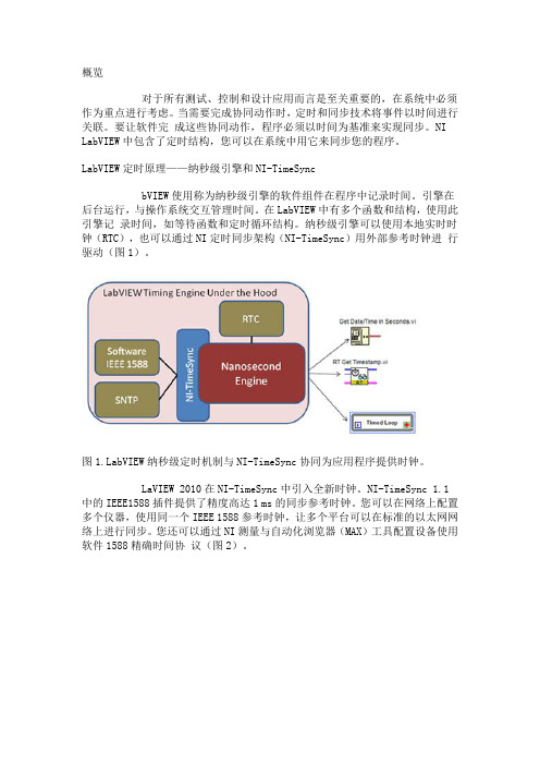
LabVIEW定时原理——纳秒级引擎和NI-TimeSyncbVIEW使用称为纳秒级引擎的软件组件在程序中记录时间。
引擎在后台运行,与操作系统交互管理时间。
在LabVIEW中有多个函数和结构,使用此引擎记录时间,如等待函数和定时循环结构。
纳秒级引擎可以使用本地实时时钟(RTC),也可以通过NI定时同步架构(NI-TimeSync)用外部参考时钟进行驱动(图1)。
图bVIEW纳秒级定时机制与NI-TimeSync协同为应用程序提供时钟。
LaVIEW 2010在NI-TimeSync中引入全新时钟。
NI-TimeSync 1.1中的IEEE1588插件提供了精度高达1 ms的同步参考时钟。
您可以在网络上配置多个仪器,使用同一个IEEE 1588参考时钟,让多个平台可以在标准的以太网网络上进行同步。
您还可以通过NI测量与自动化浏览器(MAX)工具配置设备使用软件1588精确时间协议(图2)。
图2.从MAX配置设备的时间同步源LabVIEW定时结构——定时循环定时循环是在可配置的定时源产生事件时执行的循环结构。
它可以使用多种定时源(后面的教程会有详细介绍)。
如果开发多速率处理、精确定时与同步、循环执行反馈、动态变化定时特性或多执行优先级的应用,可以使用定时循环。
除了定时循环的严密定时特性之外,定时结构还可以用于为多核编程分配处理器资源。
使用定时循环,您可以指定包括周期、优先级、期限、偏移量和延时等多个定时属性。
结合这些属性和丰富的定时源,无论需要怎样的定时方式,您都可以创建复杂的应用程序。
定时循环的定时源定时源控制定时结构的执行。
您可以从三类定时源中选择:内部定时源、软件触发或外部定时源。
labview中的的几种定时器
labview中的的几种定时器LABVIEW 提供了几种定时器(包括DELAY),如下图所示首先看看Tick Count 节点的帮助说明:返回毫秒定时器的值.基准参考时间(0 毫秒)未定义,也就是说,不能把返回的毫秒数直接转换成现实世界的时间和日期.必须注意当你使用这个函数进行比较的时候,毫秒定时器达到2 -1 后反转成0.基准参考时间未定义,说法比较模糊,难道会是个随机数,那显然不可能,如果是随机数,那两次调用TICK COUNT 取得差值就不可能表示经过的毫秒数.无论如何,必须有个时间的起点.API 函数中也有一个类似的函数:GetTickCount,该函数返回计算机启动以来经过的毫秒数.在9X 中,它读取的是BIOS 中保存的系统时钟的滴答数,早期PC 的ROM 初始化Intel8259 定时器芯片来产生硬件中断08H。
这个中断有时称为”定时器滴答”中断。
中断08H 每隔54。
925 毫秒产生一次,或大约每秒18.2 次。
BIOS 使用中断08H 更新存于BIOS 数据区的”时间”值.这就是长说的55MS 的由来.对于NT 操作系统,常规的说法是能精确到10MS,也就是说精度在1MS 时是不精确的.经过实际测试,LABVIEW 的TICK COUNT 的返回值和API 的返回值是一致的,也就是计算机启动以来经过的毫秒数.毫秒数达到2 -1 后反转成0, 可见它的数值形式是U32,最大值是2 -1,大概相当于49.7 天.对于一个连续运行的计算机,用这个节点进行比较的时候,在连续运行49.7 天后,该值自动恢复到零, 如果在这个时刻进行比较,可能会出现错误的结果.wait(ms)节点帮助文件中的解释是这样的.等待指定的毫秒数并返回毫秒定时器的值(上面提到的计算机启动以来的毫秒数).如果WAIT (MS)连接0 会强迫当前线程放弃控制权.WAIT 0MS 是一个相当重要的特点,相当于VB的DOEVENTS,CVI中的PROCESSSYTEMEVENTS,实际是归还控制权给操作系统,来处理队列中的其他消息,如果没有消息需要处理,系统马上把控制权交给这个线程,继续运。
虚拟仪器软件LabView中高精度软定时器的实现
含 的头 文件 为 Widw ;⑧ 使 用 的动 态链 接 库为 no sh
K r 12 l 。 一个 函数 是获 得系统 高精 度计数 器 e 3 i 第 me b
1 V 中定 时 器 的 实 现 方 法 C
V C中实现 定时 器基 本有 三种方 法 , 两种 的精 前 度较低 , 第三 种方 法可 以实 现高精 度 的定 时器 而
neigWok ec ) 美 国 M 公 司研 制 的一 个 功能 er rbnh 是 n
强 大 的虚拟 仪 器系统 开发 平 台 。在 L b i aVe w程 序设 计 中, 提供 的软 件 ( ) 时器 最小 只能实 现 1 s的 软 定 i n 间隔 , 法 实现精 度 更高 的软定 时 器 , 无 这就 需要 从 外
摘 要 : 用虚 拟 仪 器软 件 Lb Iw 编 制 软件 时 , 常 遇 到 用 定 时 器 采确 定数 据 采 样频 盘 的 使 av E 经
情L 兄一一般 妻现定时器的方法有两种 , 一种是使用硬件 定时器, 另一种是使用软件蝙程 来 定时 由于 L b I W 自身没有提供 时间 间隔小于 1m 的定时器 , a VE s 故提 出在 Lb IW 中通 aV E
Lb i a Ve w使 用 的软定 时器 动态链 接库 。
和 Q e 'ef n a Cu t , uDP rn mc one 使用条 件 如下 : 使 用 o e r ①
平 台为 Widw T 2 0 n o s / 0 0或 Wid w 5 9 ;② 包 N no s / 8 9
C U 类 型 P
G n 】 It e t ( ) P e un n P …i r Ⅲ … d
G m】eme1rc k 0 (m) … 0 0 e 】 I 1 ) e Tn【 n n < r 0MHz 5
LabVIEW Real-Time Module配置使用指南说明书

Using Desktop PCs as RT Targets with the LabVIEW Real-Time™ModuleThe LabVIEW Real-Time Module can execute VIs on RT targets runninga real-time operating system. This document contains importantinformation about configuring a desktop PC as an RT target andinformation about installing software on the desktop PC.Refer to the Getting Started with the LabVIEW Real-Time Moduledocument for exercises you can complete to familiarize yourself with theLabVIEW Real-Time Module.ContentsSystem Requirements (2)Configuring a Desktop PC Using a Utility USB Drive (3)Boot from the USB Drive (3)Format a Drive or Partition (4)Configuring a Desktop PC Using a Boot Disk (5)Configuring a Desktop PC Using a Format Disk (6)Installing Software (7)Installing Multiple-CPU Support (8)Resources (8)System RequirementsTo configure a desktop PC as an RT target, ensure that the PC meets thefollowing requirements:•Processor based on the x86 architecture.•Supported Ethernet chipset, the Ethernet device from the LabVIEWReal-Time Deployment License Bundle for Standard PCs, or asupported Ethernet card.•Formatted hard drive or partition on the desktop PC with the FAT32 orReliance file system. Because Windows Vista requires the NTFS filesystem, you cannot install RT Module software on the same partitionas Windows Vista.• 3.5 inch floppy drive or bootable USB port on the desktop PC.etspc for up-to-date information about supported hardware and the specific desktop PCspecifications that National Instruments recommends.Configuring a Desktop PC Using a Utility USB DriveUse a utility USB drive to configure a desktop PC to boot from the USBdrive or to format the hard drive of the desktop PC and then permanentlyinstall the RT Module software on the hard drive of the desktop PC.Create a desktop PC utility USB drive using NI Measurement &Automation Explorer (MAX). Select Tools»RT Disk Utilities»CreateDesktop PC Utility USB Drive in MAX to create the utility USB drive. Boot from the USB DriveUse a utility USB drive to configure a desktop PC to boot from the USBdrive and launch the RT Module software on the hard drive of the desktopPC. If there is no RT Module software installed on the hard drive, the utilityUSB drive boots the PC into safe mode, where you can install software.Complete the following steps to configure a desktop PC to boot using autility USB drive.1.If the desktop PC does not include a motherboard with a supportedEthernet chipset, install a supported Ethernet card or the Ethernetdevice included with the LabVIEW Real-Time Deployment LicenseBundle for Standard PCs in an available PCI slot of the PC.2.Connect a monitor and keyboard to the desktop PC to display andrespond to BIOS configuration utility prompts.Using Desktop PCs as RT © National Instruments Corporation 3Using Desktop PCs as RT TargetsNote National Instruments recommends that you remove from the desktop PC any PCI boards not supported by the LabVIEW Real-Time Module to reduce the possibility of resource conflicts. For example, remove sound cards, SCSI adapters, and modems from the desktop PC.3.Turn on the desktop PC and access the BIOS configuration utility.Note BIOS configurations and configuration interfaces for desktop PCs vary among different manufacturers and system models. Consult the motherboard or system manual for information about accessing and configuring the BIOS settings of the desktop PC.4.Set the boot configuration to use a USB drive as the first boot device. 5.Disable any unnecessary integrated peripherals that use an interruptrequest line (IRQ). For example, disable unused serial ports orintegrated sound on the desktop PC.6.Save the configuration changes and exit the BIOS configuration utility.7.Insert the utility USB drive into an empty USB port on the desktop PCand reboot the desktop PC.8.Select the Boot using software installed on the hard-disk optionfrom the utility USB drive menu. The desktop PC boots into thereal-time operating system or into safe mode. Refer to the InstallingSoftware section for information about installing the RT Modulesoftware on the hard drive if the PC boots into safe mode.Format a Drive or PartitionUse a utility USB drive to permanently install the RT Module software onthe hard drive of the desktop PC. A format option of the utility USB driveresets a previously formatted and partitioned hard drive and installs files tothe desktop PC to allow you to start the PC without a boot disk.Caution The format utility of the utility USB drive overwrites the hard drive boot sector and master boot record, erasing all pointers to data on the drive. If you have a dual-boot configuration, the changes to the master boot record remove the ability to boot into the secondary operating system.Complete the following steps to format the hard drive and configure adesktop PC using a utility USB drive.1.If the desktop PC does not include a motherboard with a supportedEthernet chipset, install a supported Ethernet card or the Ethernetdevice included with the LabVIEW Real-Time Deployment LicenseBundle for Standard PCs in an available PCI slot of the PC.2.Connect a monitor and keyboard to the desktop PC to display andrespond to BIOS configuration utility prompts.Using Desktop PCs as RT Targets Note National Instruments recommends that you remove any PCI boards not supported by the LabVIEW Real-Time Module to reduce the possibility of resource conflicts. For example, remove sound cards, SCSI adapters, and modems from the desktop PC.3.Turn on the desktop PC and access the BIOS configuration utility.Note BIOS configurations and configuration interfaces for desktop PCs vary among different manufacturers and system models. Consult the motherboard or system manual for information about accessing and configuring the BIOS settings of the desktop PC.4.Set the boot configuration to use a USB drive as the first boot device. 5.Disable any unnecessary integrated peripherals that use an interruptrequest line (IRQ). For example, disable unused serial ports orintegrated sound on the desktop PC.6.Save the configuration changes and exit the BIOS configuration utility.7.Insert the utility USB drive into an empty USB port on the desktop PCand reboot the desktop PC.8.Select the Format hard disk option from the utility USB drive menu,choose a file system, and follow the directions on the screen.Formatting with the Reliance File SystemReliance is a transactional file system that provides data integrity in theevent of a power interruption. If a FAT-formatted RT target reboots orpowers down during application execution due to power loss or userintervention, data corruption can occur. The Reliance file system maintainsdata integrity in such cases. Refer to the Datalight website at for more information about the Reliance file system.After formatting with the Reliance file system, remove the utility USBdrive and reboot the desktop PC to boot into the real-time operating system.The desktop PC boots into safe mode the first time the system boots fromthe hard drive. Refer to the Installing Software section for informationabout installing the RT Module software on the hard drive if the PC bootsinto safe mode.Formatting with the FAT File SystemFormat with the FAT file system if you need to maintain compatibility withexisting FAT-formatted systems.After formatting with the FAT file system, remove the utility USB drive andreboot the desktop PC to boot into the real-time operating system. Thedesktop PC boots into safe mode the first time the system boots from thehard drive. Refer to the Installing Softwaresection for information about© National Instruments Corporation 5Using Desktop PCs as RT Targetsinstalling the RT Module software on the hard drive if the PC boots into safe mode.Configuring a Desktop PC Using a Boot DiskYou can use a boot disk to launch the RT Module software that you installon the hard drive of a desktop PC. If there is no RT Module softwareinstalled on the hard drive, the desktop PC boots into safe mode, where youcan install software.Create a desktop PC boot disk using NI Measurement & AutomationExplorer (MAX). Select Tools»RT Disk Utilities»Create Desktop PCBoot Disk in MAX to create the desktop PC boot disk.Note You cannot create a boot disk with Windows Vista. You also cannot use a boot disk with a Reliance-formatted hard drive or partition. When you need to use a boot disk with a Reliance-formatted hard drive or partition, you can use a utility USB drive instead.Complete the following steps to configure a desktop PC using a boot disk.1.If the desktop PC does not include a motherboard with a supportedEthernet chipset, install a supported Ethernet card or the Ethernetdevice included with the LabVIEW Real-Time Deployment LicenseBundle for Standard PCs in an available PCI slot of the PC.2.Connect a monitor and keyboard to the desktop PC to display andrespond to BIOS configuration utility prompts.Note National Instruments recommends that you remove from the desktop PC any PCI boards not supported by the LabVIEW Real-Time Module to reduce the possibility of resource conflicts. For example, remove sound cards, SCSI adapters, and modems from the desktop PC.3.Turn on the desktop PC and access the BIOS configuration utility.Note BIOS configurations and configuration interfaces for desktop PCs vary among different manufacturers and system models. Consult the motherboard or system manual for information about accessing and configuring the BIOS settings of the desktop PC.4.Set the boot configuration to use the floppy drive as the first boot device. 5.Disable legacy USB support. 6.Disable any unnecessary integrated peripherals that use an interruptrequest line (IRQ). For example, disable unused serial ports orintegrated sound on the desktop PC.7.Save the configuration changes and exit the BIOS configuration utility.Using Desktop PCs as RT Targets 8.Insert the desktop PC boot disk in the floppy drive and reboot thedesktop PC. The desktop PC boots into the real-time operating systemor into safe mode. Refer to the Installing Software section forinformation about installing the RT Module software on the hard drive if the PC boots into safe mode.Configuring a Desktop PC Using a Format DiskYou can use a format disk to permanently install the RT Module softwareon the hard drive of the desktop PC. A format disk resets a previouslyformatted and partitioned hard drive and installs files to the desktop PC toallow you to start the PC without a boot disk.Create a desktop PC format disk using NI Measurement & AutomationExplorer (MAX). Select Tools»RT Disk Utilities»Create Desktop PCFormat Hard Drive Disk in MAX to create the desktop PC format disk.NoteYou cannot create a format disk with Windows Vista. You can use a format disk to format with the FAT file system only. To format with the Reliance file system, you must use a utility USB drive.Caution A format disk overwrites the hard drive boot sector and master boot record, erasing all pointers to data on the drive. If you have a dual-boot configuration, the changes to the master boot record remove the ability to boot into the secondary operating system.Complete the following steps to configure a desktop PC using a formatdisk.1.If the desktop PC does not include a motherboard with a supportedEthernet chipset, install a supported Ethernet card or the Ethernetdevice included with the LabVIEW Real-Time Deployment LicenseBundle for Standard PCs in an available PCI slot of the PC.2.Connect a monitor and keyboard to the desktop PC to display andrespond to BIOS configuration utility and format prompts.Note National Instruments recommends that you remove from the desktop PC any PCI boards not supported by the LabVIEW Real-Time Module to reduce the possibility of resource conflicts. For example, remove sound cards, SCSI adapters, and modems from the desktop PC.3.Turn on the desktop PC and access the BIOS configuration utility.Note BIOS configurations and configuration interfaces for desktop PCs vary among different manufacturers and system models. Consult the motherboard or system manual forinformation about accessing and configuring the BIOS settings of the desktop PC.© National Instruments Corporation 7Using Desktop PCs as RT Targets4.Set the boot configuration to use the floppy drive as the first boot device. 5.Disable legacy USB support. 6.Disable any unnecessary integrated peripherals that use an interruptrequest line (IRQ). For example, disable unused serial ports orintegrated sound on the desktop PC.7.Save the configuration changes and exit the BIOS configuration utility.8.Insert the desktop PC format disk in the floppy drive and reboot the PC.9.Follow the directions that appear on the screen. 10.Remove the desktop PC format disk from the floppy drive and rebootthe desktop PC to boot into the real-time operating system. Thedesktop PC boots into safe mode the first time the system boots fromthe hard drive. Refer to the Installing Software section for informationabout installing the RT Module software to the hard drive if the PC boots into safe mode.Installing SoftwareComplete the following steps to install software on the desktop PC.1.Boot the desktop PC into the real-time operating system. The desktopPC loads with the basic real-time operating system and a null IPaddress of 0.0.0.0.Tip You can connect a monitor to the desktop PC to display startup messages.2.Open MAX on another computer in the same subnet and expand theRemote Systems category. MAX lists the desktop PC as 0.0.0.0 inthe Remote Systems category.3.Click on the 0.0.0.0 entry to access the Network Settings tab.4.Enter a name for the RT target in the Name text box.5.Set the network configuration options of the RT target in theIP Settings section and click the Apply button.Refer to the Configuring Network Settings book, accessible bybrowsing to MAX Remote Systems Help»LabVIEW Real-TimeTarget Configuration»Configuring Network Settings from theContents tab of the MAX Help , for information about configuringnetwork settings .6.Reboot the RT target. The RT target appears in the Remote Systems category with the assigned name. 7.Expand the RT target in the Remote Systems category and select theSoftwarecategory.National Instruments, NI, , and LabVIEW are trademarks of National Instruments Corporation.Refer to the Terms of Use section on /legal for more information about NationalInstruments trademarks. Other product and company names mentioned herein are trademarks or tradenames of their respective companies. For patents covering National Instruments products, refer to theappropriate location: Help»Patents in your software, the patents.txt file on your CD, or/patents .© 2004–2007 National Instruments Corporation. All rights reserved.371857E-01Dec078.Click the Add/Remove Software button in the toolbar to launch the LabVIEW Real-Time Software Wizard. 9.Install the LabVIEW Real-Time software and device drivers that yourequire on the RT target. Refer to the NI Web site at /info andenter the info code etspc for the latest information about supported software.Installing Multiple-CPU SupportTo take advantage of parallel processing on a multiple-CPU system, use theLabVIEW Real-Time Software Wizard in MAX to install the NI RTExtensions for SMP. Refer to the MAX Help for information about using theLabVIEW Real-Time Software Wizard. Refer to the Optimizing RTApplications for Multiple-CPU Systems book of the LabVIEW Help forinformation about optimizing RT applications for multiple-CPU systems.Note Single-CPU systems perform best without the NI RT Extensions for SMP. Also, some applications, such as those that consist mainly of single-point I/O, can achieve lower latency using a single CPU without the NI RT Extensions for SMP. Refer to the National Instruments Web site at /info and enter the info code rtsmp for further details about optimizing RT applications for systems with multiple CPUs.Resources•Refer to the NI Web site at /info and enter the info code etspc for more information about using desktop PCs as RT targets.•Refer to the readme_RT.html file on the LabVIEW Real-TimeModule installation CD for information about known issues regardingthe use of desktop PCs as RT targets.•Refer to the Getting Started with the LabVIEW Real-Time Moduledocument for exercises you can complete to familiarize yourself withthe LabVIEW Real-Time Module.•Refer to the LabVIEW Help for more information about the LabVIEWReal-Time Module features. Access the LabVIEW Help fromLabVIEW by selecting Help»Search the LabVIEW Help .。
[整理版]USB-6211和WLS-9163的使用总结
![[整理版]USB-6211和WLS-9163的使用总结](https://img.taocdn.com/s3/m/2e26120015791711cc7931b765ce05087632751b.png)
USB-6211的使用总结00USB-6211是一款总线供电USB M系列多功能DAQ模块,其在高采样率下也能保持高精度。
该模块提供了16路模拟输入;2路模拟输出;4路数字输入线路;4路数字输出线。
每通道有四个可编程输入范围:±0.2V;±1V;±5V;±10V。
该模块还有数字触发,计数器/定时器单元。
USB-6211模块具有新的NI信号读写技术,实现了USB总线上类似DMA的双向高速数据流操作。
对于该模块的使用基于使用软件的不同,我把它分为两部分:基于MAX的使用和基于应用软件LabVIEW的使用。
001、基于MAX001、安装NI-DAQmx00安装NI-DAQmx驱动程序软件,将设备随附的光盘插入计算机,可使Windows检测出设备,完成安装。
002、USB设备识别00打开NI设备监视器,Windows监测到新安装的设备后,NI设备监视器在启用时会自动运行。
选择开始>>所有程序»National Instruments»NI-DAQ»NI 设备监视器,然后00插入设备.00①打开MAX;00②展开设备和接口,确认MAX 已识别NI USB 设备。
若识别到该设备,则在设备和接口的子窗口NI-DAQmx设备下出现NI USB-6211.00③设备的自检。
右键单击NI USB设备名选择自检,或在选定设备后,在右边窗口单击自检。
自检结束后,提示信息将显示检测成功。
003、运行测试面板00右键单击设备,选择测试面板,打开设备的测试面板。
然后单击开始,测试设备功能。
00在MAX中,它还能通过创建数据采集任务来进行采集,与下面要介绍的方法类似,就不多加赘述。
结合应用程序来使用NI USB设备,我使用的应用程序是LabVIEW,下面就重点介绍在LabVIEW中的使用。
002、基于应用程序LabVIEW的使用00在确定USB-6211设备被识别后,就可以在应用程序LabVIEW中使用了,DAQ助手模块实现了设备的设置。
利用LabVIEW进行电机控制与调试

利用LabVIEW进行电机控制与调试LabVIEW(Laboratory Virtual Instrument Engineering Workbench)是一款基于图形化编程语言的开发环境,广泛应用于科学与工程领域的数据采集、分析、控制以及调试等方面。
本文介绍如何利用LabVIEW进行电机控制与调试,包括步进电机和直流电机的控制方法以及相关调试技巧。
一、步进电机控制步进电机是一种离散控制的电机,通过对电机驱动成组的正向或反向脉冲信号,实现旋转角度的精确控制。
LabVIEW提供了丰富的工具和函数来实现步进电机的控制。
首先,在LabVIEW中创建一个新的VI(Virtual Instrument)文件。
在Block Diagram中选择一个While Loop,并在循环内部添加若干个控制步进电机运动的代码。
例如,可以通过控制单个IO口的高低电平来实现脉冲信号的输出。
使用LabVIEW中的Digital Output模块,将其配置为输出模式,并将其与步进电机驱动器的脉冲接口连接。
然后,在每次循环迭代中,将该IO口的电平设置为高电平,然后延时适当时间,再将其设置为低电平,即可输出一个脉冲信号。
此外,还可以通过使用计数器或定时器模块来生成脉冲信号。
LabVIEW中的Counter和Timer模块可以方便地设置计数器的初值、计数范围以及计数速率。
通过适当的配置和调试,可以实现步进电机的精确控制。
二、直流电机控制直流电机是一种常见的电动机类型,广泛应用于各种机械设备中。
LabVIEW也提供了多种方法来实现直流电机的控制。
首先,在LabVIEW中创建一个新的VI文件。
使用LabVIEW中的Analog Output模块来生成电机驱动信号。
将Analog Output模块与直流电机驱动器的控制端口连接,通过调整模块输出的电压值,可以实现对直流电机的转速和方向的控制。
LabVIEW还提供了PID控制器模块,可用于进一步优化直流电机的控制效果。
LabVIEW Real-Time 模块发行 和升级说明 2011 版本说明书
LabVIEW Real-Time 模块发行和升级说明2011版本文档介绍LabVIEW Real-Time 模块2011版的系统要求、安装须知、新功能概述,以及升级和兼容性问题。
请阅读LabVIEW Real-Time 模块入门指南,了解和熟悉Real-Time 模块。
提示关于使用LabVIEW Real-Time 模块设计、开发和部署应用程序的说明和建议,请参考LabVIEW 帮助中的Real-Time 模块最佳惯例部分。
在LabVIEW 帮助的目录栏中选择Real-Time 模块»Real-Time 模块最佳惯例,即可查看相关内容。
目录系统要求..............................................................................................................................................................2安装Real-Time 模块2011...........................................................................................................................2激活Real-Time 模块......................................................................................................................................2配置Real-Time 终端......................................................................................................................................3Real-Time 模块2011版的新功能............................................................................................................3在LabVIEW 开发环境之外部署独立应用程序.........................................................................3配置EPICS Server I/O 服务器的改进...........................................................................................3EPICS Client I/O 服务器支持............................................................................................................3新增VI.........................................................................................................................................................4Real-Time Execution Trace 工具包........................................................................................................4激活Real-Time Execution Trace 工具包...................................................................................4升级和兼容性问题...........................................................................................................................................4Real-Time 模块2011版的已知问题........................................................................................................5参考资料..............................................................................................................................................................5相关文档和范例......................................................................................................................................5NI 网站........................................................................................................................................................5技术支持. (5)™LabVIEW Real-Time 模块发行和升级说明/china 系统要求表1是运行LabVIEW Real-Time 模块2011版的系统要求。
【毕业论文】基于LabVIEW的多功能秒表设计(计时器+倒计时+节拍器+日历+时钟)
基于LabVIEW的秒表设计摘要数字式秒表是一种常用的计时工具,广泛用于各种比赛以及各类实验测量中。
随着生活节奏的加快,人们时间观念的加强,各种计时器已经成为人们日常生活中不可或缺的一部分,并且人们已经不能满足于单一的某一种功能了。
而如何在秒表的基础上,根据人们生活的需要增加相应的功能以方便人们的生活,便成为秒表设计方面的重点。
我基于LabVIEW设计的的秒表,具有秒表计时器、倒计时器、节拍器、时钟和闹钟的功能。
其具有界面美观,简单易用,功能强大,精确度高等特点。
此秒表的所有功能均可以独立运行,互不干扰,具有很好的用户体验。
关键词:秒表,计时,LabVIEWStopwatch design based on LabVIEWAbstractDigital stopwatch is a commonly used tool for timing.It is widely used in various competitions and a variety of experimental measurements.With the accelerated pace of life and the strengthening of the concept of time,variety timer has become an indispensable part of everyday life,and it has been unable to meet on a single feature of a certain kind.It has become the focus of the stopwatch design that how to add the corresponding function according to the needs of people's lives based on the stopwatch to convenience to people's lives.Stopwatch witch I designed based on LabVIEW, is with a stopwatch timer, countdown timer, metronome, clock and alarm functions.It has a beautiful interface, easy to use, powerful, high precision characteristics.This stopwatch’s all functions can be run independently, means can without disturbing each other, and with good user experience.Keywords: stopwatch, timer, LabVIEW目录1.绪论 (1)1.1 引言 (1)1.2虚拟仪器的概念及特点 (1)1.2.1虚拟仪器 (1)1.2.2 虚拟仪器的特点 (1)2. 图形化编程和LabVIEW (2)2.1 图形化编程简介 (2)2.2 LabVIEW简介 (2)2.2.1前面板 (2)2.3.2 程序框图 (2)3.秒表介绍及程序设计 (3)3.1 概述 (3)3.2 秒表的发展 (3)3.3 秒表的功能设计 (5)3.3.1.正计时 (5)3.3.2 倒计时 (6)3.3.3.节拍器 (6)3.3.4.时钟与闹钟 (6)4. 程序实现 (7)4.1秒表计时器 (7)4.1.1 流程图 (7)4.1.2程序设计 (8)4.2 倒计时器 (21)4.2.1流程图 (21)4.2.2程序设计 (22)4.3节拍器 (25)4.3.1流程图 (25)4.3.2 程序设计 (26)4.4时钟及闹钟 (28)4.4.1流程图 (28)4.4.2 程序设计 (28)总结 (31)致谢 (33)1.绪论1.1 引言LabVIEW是一种程序开发环境,由美国国家仪器(NI)公司研制开发的,类似于C和BASIC开发环境,但是LabVIEW与其他计算机语言的显著区别是:其他计算机语言都是采用基于文本的语言产生代码,而LabVIEW使用的是图形化编辑语言G编写程序,产生的程序是框图的形式。
- 1、下载文档前请自行甄别文档内容的完整性,平台不提供额外的编辑、内容补充、找答案等附加服务。
- 2、"仅部分预览"的文档,不可在线预览部分如存在完整性等问题,可反馈申请退款(可完整预览的文档不适用该条件!)。
- 3、如文档侵犯您的权益,请联系客服反馈,我们会尽快为您处理(人工客服工作时间:9:00-18:30)。
labview深入探索----谈谈LABVIEW的几种定时器2008-04-27 15:29
LABVIEW提供了几种定时器(包括DELAY),如下图所示
1.首先看看Tick Count 节点的帮助说明:
返回毫秒定时器的值.
基准参考时间(0 毫秒)未定义,也就是说,不能把返回的毫秒数直接转换成现实世界的时间
和日期.必须注意当你使用这个函数进行比较的时候,毫秒定时器达到2^32-1后反转成0. 基准参考时间未定义,说法比较模糊,难道会是个随机数,那显然不可能,如果是随机数,那两次调用TICK COUNT取得差值就不可能表示经过的毫秒数.无论如何,必须有个时间的起点.
API函数中也有一个类似的函数:GetTickCount,该函数返回计算机启动以来经过的毫秒数.在9X中,它读取的是BIOS中保存的系统时钟的滴答数,早期PC的ROM初始化Intel8259定时器芯片来产生硬件中断08H。
这个中断有时称为"定时器滴答"中断。
中断08H每隔54。
925毫秒产生一次,或大约每秒18.2次。
BIOS使用中断08H更新存于BIOS数据区的"时间"值.这就是长说的55MS的由来.对于NT操作系统,常规的说法是能精确到
10MS,也就是说精度在1MS时是不精确的.
经过实际测试,LABVIEW的TICK COUNT的返回值和API的返回值是一致的,也就是计算机启动以来经过的毫秒数.
毫秒数达到2^32-1后反转成0,可见它的数值形式是U32,最大值是2^32-1,大概相当于49.7天.对于一个连续运行的计算机,用这个节点进行比较的时候,在连续运行49.7天后,该值自动恢复到零,如果在这个时刻进行比较,可能会出现错误的结果.
2.wait(ms)节点帮助文件中的解释是这样的.
等待指定的毫秒数并返回毫秒定时器的值(上面提到的计算机启动以来的毫秒数).如果WAIT (MS)连接0会强迫当前线程放弃控制权.
WAIT 0MS是一个相当重要的特点,相当于VB的DOEVENTS,CVI中的PROCESSSYTEMEVENTS,实际是归还控制权给操作系统,来处理队列中的其他消息,如果没有消息需要处理,系统马上把控制权交给这个线程,继续运行.
这里有两种情况,如果系统消息队列中无需要处理的消息,立即返回,如果系统消息队列中有消息需要处理,并且是一个耗时操作,无法预料LV线程何时再次取得控制权.我们比较LV是否加WAIT0MS的速度.
实验过程中未执行其它任何操作,避免了处理其他消息造成的影响.两者之间,差距是惊人的.这也体现了LABVIEW的一个优点,对于一个倾向于硬件控制的编程软件,它有着极强的任务抢先能力.
在一个循环里多次并行执行WAIT,是累加时间,还是按最长的执行那,实际上是异步的还是同步的问题.我们做一下实验.
可见,这三个WAIT是同时执行的.
由于WAIT是基于线程的,一个循环里的WAIT不会影响同时运行的其它线程的运行.3.看看WAIT UNTIL NEXT MS MULTIPULE(等待下一个毫秒的整数倍).
一直等到毫秒定时器变成指定时间的整数倍.可以用于在一个循环中调节循环的执行速率.
但是第一次的循环周期可能比较短.可以直接连接0到这个节点,强迫当前线程放弃控制权,归还给CPU.
相比WAIT MS,这个节点在循环中更为常用,对于几个采用相同参数的WAIT UNTIL NEXT MS MULTIPULE,可以实现不特别精确的同步.由于LABVIEW的循环的特点,首次是立即执行的,所以第一次是不能保证同步的.如果必须要保证同步的话,可以在循环中第一次执行空循环来避免这个问题.
LABVIEEW EXPRESS中也提供了两个快速VI,一个相当于WAIT MS,另一个可以实现非常复杂的定时功能.
4.我们先把TIME DELAY EXPRESS VI转换成常规VI,跟踪一下它是如何实现的.
进一步跟踪SUBTIMEDELAY
可见,实际上还是调用的WAITMS,不过是数据类型换成的DOUBLE,表示秒数,同时增加了错误簇,有利于实现顺序延时动作.其他完全等同于DEALYMS.
可能是在LV7.1后新增加了这个ELAPSED TIME快速节点,这是一个非常有用的定时器.先介绍一个OPENG中提供的比较简单的定时器.
这是一个周期软件定时器.可用于周期性地循环触发事件.
看看它是如何实现的.
LV的elapsed time 功能远比上面的VI功能强大,可以实现复杂的控制功能.
1.循环定时触发一个事件.
2.输出一个方波(5秒)
3.PWM波形.
4.系统时钟。