Brosur WI hal.1 2014
安全光栅GuardShield 450L-E说明书

The Allen-Bradley® GuardShield™ 450L-E Safety Light Curtains fromRockwell Automation are based on a unique patented transceiver technology which allows each stick to be used as a transmitter or as a receiver. The full functionality of a transceiver is provided by plug-ins inserted at the bottom of the sticks. By using only one stick type with the optimal plug-ins selected based on the requirements of the application, the GuardShield 450L portfolio is a simple, cost effective solution that offers enhanced flexibility while maintaining the highest level of safety.The enhanced Integrated Laser Alignment System (ILAS) of the GuardShield 450L-E reduces installation time by providing multiple visible laser points that optimize setup with a simple touch of the ILAS symbol on the front window of the stick. Plus, the compact design and full length protective field make it easy to integrate a GuardShield 450L-E system in hand and finger protection applications from 150 mm (5.9 in.) up to 1950 mm (76.7 in.) in increments of 150 mm (0.5 ft).The enhanced GuardShield 450L-E light curtain system is also ideal for special applications requiring advanced functions such as muting and blanking,easily set up through DIP switches located on the dedicated plug-in modules. For muting, the common set ups like 4-sensor or 2-sensor with L- and T-configuration and override function can be selected. Blanking, reducedresolution, floating blanking and teach-in fixed blanking features are available. Configure up to eight protection zones via CCW software. A cascading plug-in can also be installed for series connection of additional GuardShield 450L Safety Light Curtain systems for multi-sided machine guarding (up to four sides). All these special functions combined with the inherent flexibility of the GuardShield 450L transceiver design help to simplify your engineering logistics and minimize the stock required to address your full range of applications.For configuration, monitoring and troubleshooting, our free Connected Components Workbench software is available at our website. A separate optical interface tool is required if using Connected Components Workbench software for diagnostic information.Features and Benefits• Extended features and functionality compared to the 450L-B such as cascading, built-in muting,blanking and multiple applications configuration• Embedded functions configured quickly and easily via DIP switches or software, significantly reducing engineering effort. These include:– M uting, blanking, start mode, external device monitoring (EDM), scanning range• Leverages patented transceiver technology – each stick can be used as a transmitter or receiver via innovative plug-in modules• Enhanced Integrated Laser Alignment System (ILAS) for quick installation and reliable operation• Active protective field provides sensing over the entire length of a transceiver• Compact design 30 mm x 30 mm (1.18 in. x 1.18 in.)• Wide range of protection heights 150…1950 mm (5.9…76.7 in.) in increments of 150 mm (0.5 ft)• Resolutions:– F inger resolution (14 mm): 0.5 to 9 m (1.64…29.53 ft)– H and resolution (30 mm): 0.9 to 16.2 m (2.95…53.15 ft)• Supports cascading of multiple systems in series• Flexible mounting options allow for quick and easy installation• Configure, monitor and troubleshoot via Connected Components Workbench (CCW) software.Pre-configure multiple configurations. • IP65 enclosure rating• TÜV certified Type 4 IEC 61496-1/-2, Ple, SILcl3 per EN ISO 13849-1,IEC 62061Allen-Bradley GuardShield 450L-E Safety Light CurtainEnhanced Flexibility and Advanced Features in a Cost-Effective Safety SolutionRequired Accessories 1Replace the x with 2 (6.6 ft), 5 (16.4 ft), 10 (32.8 ft), 15 (49.2 ft), 20 (65.6 ft), or 30 (98.4 ft) for available lengths in metersOptional Accessories*Requires 450L fw version 4.00x and CCW R12 at minimum.1xxxx = 0150…1950 mm (0.5…6.4 ft) in increments of 150 mm (0.5 ft)Innovative plug-in modulesestablish transceiver as an emitter orreceiver and provide other advanced functions.Integrated Laser Alignment System accelerates setup for optimal performance at the touch of a button.General Ordering InformationLight Curtain System: Order two identical transceivers/catalog numbers. Plug-in Modules: Order one transmitter and one receiver plug-in with the desired functionality for one system – or – Order two universal plug-ins for one system. Each universal plug-in can be used as a transmitter or a receiver. To cascade systems or for muting options use thecascading plug-in.1xxxx = 0150 … 1950 mm (0.5 … 6.4 ft) in increments of 150 mm (0.5 ft).For example: “450L-E4HL 0900YD” indicates an order for 900 mm hand detection light curtain transceiver.2Optional side mounting bracket kit is available below.1 The 8-pin transmitter plug-in option allows two 8-pin cordsets to be used in one system.2Order two universal plug-ins for one system. Each universal plug-in can be used as a transmitter or a receiver.Publication 450L-PP002B-EN-P – May 2020 | Supersedes Publication 450L-PP002A-EN-P – January 2018Copyright © 2020 Rockwell Automation, Inc. All Rights Reserved. Printed in USA.Allen-Bradley, Connected Components Workbench, Expanding human potential and GuardShield are trademarks of Rockwell Automation, Inc.Trademarks not belonging to Rockwell Automation are property of their respective companies.Connect with us.。
Brocade Vyatta 网络操作系统产品指南说明书

Supporting Brocade 5600 vRouter, VNF Platform, and DistributedServices PlatformsFEATURE GUIDE53-1004752-01© 2016, Brocade Communications Systems, Inc. All Rights Reserved.Brocade, the B-wing symbol, and MyBrocade are registered trademarks of Brocade Communications Systems, Inc., in the United States and in other countries. Other brands, product names, or service names mentioned of Brocade Communications Systems, Inc. are listed at /en/legal/ brocade-Legal-intellectual-property/brocade-legal-trademarks.html. Other marks may belong to third parties.Notice: This document is for informational purposes only and does not set forth any warranty, expressed or implied, concerning any equipment, equipment feature, or service offered or to be offered by Brocade. Brocade reserves the right to make changes to this document at any time, without notice, and assumes no responsibility for its use. This informational document describes features that may not be currently available. Contact a Brocade sales office for information on feature and product availability. Export of technical data contained in this document may require an export license from the United States government.The authors and Brocade Communications Systems, Inc. assume no liability or responsibility to any person or entity with respect to the accuracy of this document or any loss, cost, liability, or damages arising from the information contained herein or the computer programs that accompany it.The product described by this document may contain open source software covered by the GNU General Public License or other open source license agreements. T o find out which open source software is included in Brocade products, view the licensing terms applicable to the open source software, and obtain a copy of the programming source code, please visit /support/oscd.ContentsBrocade Vyatta Network OS (5)Overview (5)Brocade Vyatta Network OS Use Cases (7)Brocade 5600 vRouter (7)Brocade Vyatta Network OS as a VNF platform (7)Brocade Vyatta Network OS as a Distributed Services platform (8)Contacting Brocade (11)Brocade Vyatta Network OS•Overview (5)OverviewThe Brocade Vyatta Network OS lays the foundation for a flexible, easy-to-use, and high-performance network services architecture capable of meeting current and future network demands. The Brocade Vyatta Network OS can be deployed across a wide variety of use cases. For example, it can be deployed as a Brocade 5600 vRouter, VNF platform, or distributed services platform to integrate into cloud, virtual, physical, or on-premises environments. It also can be deployed as a co-resident on the hardware that houses the data planes, or centralized to manage a number of distributed data planes, depending on the requirements of an organization.With the Brocade Vyatta Network OS, organizations can bridge the gap between traditional and new architectures, leverage existing investments, and maximize operational efficiencies when enabling new services. The Brocade vPlane technology comprises these main components:•Control plane—Carries signaling traffic and manages configuration and protocol operations; it also serves the data plane. The control plane consists of the following components:–Vyatta CLI, API, and GUI—Provide the user interfaces to the router–System daemons—Provide control plane services, such as BGP, DHCP, OSPF, RIP, and SNMP–Controller daemon—Provides the data plane interface to the Linux kernel and CLI and manages the data plane •Data plane—Forwards traffic between ports and passes local traffic to the controller. The data plane consists of the following components:–Data plane daemon—Provides packet forwarding, QoS, and firewall services–User space I/O drivers—Provide the network interface•Linux kernel—Hosts the data plane and other processes for the user space.Figure 2 on page 7 illustrates the Brocade Vyatta Network OS Architecture diagramFIGURE 1 Brocade Vyatta Network OS ArchitectureBrocade Vyatta Network OS Use Cases •Brocade 5600 vRouter (7)•Brocade Vyatta Network OS as a VNF platform (7)•Brocade Vyatta Network OS as a Distributed Services platform (8)Brocade 5600 vRouterThe Brocade 5600 vRouter employs the innovative Brocade vPlane technology, which enables hardware-like routing performance in a software-based network appliance. The Brocade vPlane technology comprises these main components:•Control plane: Carries signaling traffic and manages configuration and protocol operations; it also serves the data plane.•Data plane—Forwards traffic between ports and passes local traffic to the controller.•Linux kernel—Hosts the data plane and other processes for the user space.Figure 2 illustrates the Brocade 5600 vRouter in a single node instantiation.FIGURE 2 Architecture of Brocade Vyatta Network OS as a 5600 vRouter deploymentCustomarily, packet processing in Linux runs in the kernel space. However, with the vPlane architecture, packet processing runs in the Linux user space. By using the vPlane architecture and leveraging the Intel Data Plane Development Kit (Intel DPDK), the Brocade vRouter delivers breakthrough levels of performance. Depending on the configuration, one or two cores are dedicated to each interface. The core or cores are able to run at 100-percent efficiency when processing packets and support performance scaling. Brocade Vyatta Network OS as a VNF platformThe Brocade Vyatta Network OS as a VNF platform supports foundation networking services and can eliminate the need for at least one virtual network function (VNF) in a multiservice design. This platform also eliminates manual provisioning by supporting zero-touch deployment for the on-premise VNF platform, which automates configuration and software updates and allows service providers to scale services as needed. NETCONF supports the VNF life cycle, service chains, and further configuration.The Brocade Vyatta Network OS as a VNF platform is based on the Brocade Vyatta Network OS of the Brocade 5600 vRouter.Brocade Vyatta Network OS as a Distributed Services platformThe VNF platform allows the virtualization of the hardware that is required to run your business and provides a set of value-added services, including network connectivity.You can use the VNF platform to run various VNF devices.The following figure illustrates the VNF platform architecture. The VNF platform is a use case of the Vyatta Network OS. You install the hypervisor image and then create guests for various VNF roles.Architecture of Brocade Vyatta Network OS as a VNF platform deploymentFIGURE 3The Brocade Vyatta Network OS as a Distributed Services platform is a large-scale distributed router consisting of a single Distributed Services platform controller and multiple virtual data planes (vPlanes) that operate together as a large distributed system across many hypervisors. The Distributed Services Platform provides the following:•Horizontal scaling of VNFs, with numerous tenant-facing interfaces that are distributed across multiple vPlanes for Internet service providers.• A Layer 2 virtual overlay network for cloud service providers.The following figure provides a high-level view of the Distributed Services platform architecture, which is based on the following elements:•Controller—Virtual machine (VM) that provides control and management functions for the Distributed Services platform infrastructure.•vPlane—VM that forwards data as an instance of the data-forwarding plane. A single Distributed Services platform can include up to 32 vPlanes. Internal vPlanes connect to tenant servers, and gateway vPlanes connect to the external network.•Control network—Network that provides control plane and status communications between the Distributed Services Platform controller and vPlanes.•Fabric network—Full mesh of VXLAN-GPE tunnels between all the vPlanes that is used to forward packets between vPlanes.FIGURE 4Architecture of Brocade Vyatta Network OS as a Distributed Services platform deployment Brocade Vyatta Network OS as a Distributed Services platformContacting BrocadeT o provide document feedback use the online feedback form in the HTML documents posted on or contact*************************.For product support information and the latest information on contacting the T echnical Assistance Center, go to / services-support/index.html.If you have purchased Brocade product support directly from Brocade, use one of the following methods to contact the BrocadeT echnical Assistance Center 24x7. Brocade OEM customers contact their OEM/Solutions provider.Brocade Vyatta Network OS Product Guide, 5.2R153-1004752-0111。
欧米达温度记录仪产品说明书
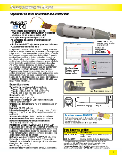
R EGISTRADORES DED ATOSU S e conecta directamente al puerto USB para una fácil configuración y descarga de datos, no se requiere cable USB U A cepta termopares de tipo J, K o T U 2 umbrales de alarma programables por el usuarioU I ndicación de LED rojo, verde y naranja brillantes U A dvertencia de batería bajaEl registrador de datos OM-EL-USB-TC mide y almacena más de 32.000 lecturas de temperatura de un termopar tipo J, tipo K o tipo T que se conecta a un receptáculo miniatura hembra para termopar en la base de la unidad. El usuario puede establecer fácilmente los parámetros de registro de datos iniciales, incluido tipo de termopar, velocidad de registro, hora de inicio, configuraciones de alarma alta/baja, modo de registro y unidades de temperatura deseadas(°C o °F) y también descargar los datos almacenados conectando el módulo en el puerto USB de un ordenador y ejecutando el software para Windows fácil de usar.Posteriormente, los datos se pueden mostrar en un gráfico, imprimirse y exportarse a otras aplicaciones como Excel. El registrador de datos se proporciona con una batería de litio de larga duración. El estado del registrador de datos se indica por medio del parpadeo de luces LED rojas, verdes y naranjas. Especificaciones Variación de medición de temperatura:T ipo J: -130 a 900 °C (-202 a 1.652 °F) Tipo K: -200 a 1.300 °C (-328 a 2.372 °F) Tipo T: -200 a 350 °C (-328 a 662 °F)Resolución: 0,5 °C (1 °F)Precisión: ±1,0 °C (±2,0 °F)Conexión del termopar: Conector subminiatura h embra para termopar Unidades de temperatura: °C o °F seleccionable en software Memoria: 32.000 lecturas Intervalo de registro: 1 seg., 10 seg., 1 min., 5 min., 30 min., 1 hora, 6 horas, 12 horas (seleccionable en software)Alarmas altas/bajas: Seleccionable en software Hora/fecha de inicio: Seleccionable en software Rango de temperatura de funcionamiento: -10 a 40 °C (-14 a 104 °F)Indicadores visuales (LED): 2 LED: el primer LED parpadea en color naranja para indicar un problema con el registrador de datos, por ejemplo batería baja; el seg-undo LED indica estado de alarma y parpadea en color verde (temperatura dentro de los límites) o en color rojo (temperatura fuera de los límites).Software: Windows ® 2000/XP/VIST A/7 (32 y 64 bits)Potencia: 1⁄2 batería de litio AA de 3,6 V (incluido)Vida útil de la batería: 6 meses (a 25 °C e intervalo de registro de 1 minuto)Peso: 43 g (1,5 onzas)Dimensiones: Vea la ilustración arriba, a la derecha Registrador de datos de termopar con interfaz USB configuración del software para Windows Soporte de bolsillo (incluido)Tapa de protección (incluido)operador en CD-ROM, tapa de protección, sujetador para bolsillo, termopar tipo K y batería de litio de 3,6 V .Ejemplo de pedido: OM-EL-USB-TC, registrador de datos de termopar con interfaz USB y OM-EL-BATT , batería de reemplazo.Incluye un termopar tipo K de alambre rebordeado aislado de 1 m (40") gratuito con conector subminiatura y soporte de carrete para alambre. Solicite un recambio Modelo Nº SC-GG-K-30-36.Se incluye termopar GRATUITO。
GRANDEUR Hybrid 2.4 特色版全选全选装版说明书

Air cleaning mode is activated by pressing and holding the internal / external button for two seconds. For safety purposes, use of the Passenger Relaxation Comfort Seat function is recommended when parking or at a stop.
Controlled
deceleration
Controlled deceleration
Return to previous speed
"DUJWF"JS'MBQ CVJMUJOUPUIFSBEJBUPSHSJMMF
"JSDVSUBJO
$POUFOUTGPS)ZCSJEPOMZ
recharge the battery, improving the vehicle’s overall energy efficiency.
2. Hybrid high-voltage battery with a lifetime warranty
The longevity of the GRANDEUR Hybrid’s battery is guaranteed by
Cork garnish on the door panels for Hybrid only
Cluster for Hybrid only (4.2" color LCD)
Hybrid emblem
17-inch aerodynamic alloy wheel for Hybrid only
Leica RM2125和RM2125 RT旋转微摆机说明书

Flexible specimen handling Proven knife holder systemThe universal knife holder base isSafe, ergonomic handwheel Safety is a number one priority in Efficient trimming function Optional specimen retraction State-of-the-art specimenclamping systemThe proven quick-release speci-Optional section waste trayThe generously sized section Easy-to-clean housingLeica Design by Werner HölblHorizontal specimen feed:approx. 28 mm Vertical specimen stroke length:60 mm (+/–1 mm)Specimen orientation (x/y):8°Trimming thickness selections:10 and 50 µmSpecimen retraction:220 µmDimensions (L x H x W):470 x 400 x 295 mmWeight (net, w/o accessories):29 kgSection thickness setting:0.5 –60 µmfrom 0 –2 µm in 0.5 µm steps from 2 –10 µm in 1 µm steps from 10 –20 µm in 2 µm steps from 20 –60 µm in 5 µm stepsSection thickness indication:visual displayCoarse feed:manual, via coarse feed wheelWide range of accessories available on request.Technical specifications subject to change without prior notice.State-of-the-art R&D, manufacturing and q uality assurance procedures – registered under DIN EN ISO 9001 – ensure hig-hest quality and reliability.Leica RM2125RT – Technical SpecificationLeica RM2125 – Technical SpecificationHorizontal specimen feed:approx. 28 mm Vertical specimen stroke length:60 mm (+/–1 mm)Specimen orientation (x/y):8°Dimensions (L x H x W):470 x 400 x 295 mmWeight (net, w/o accessories):29 kgSection thickness setting:0.5 –60 µmfrom 0 –2 µm in 0.5 µm steps from 2 –10 µm in 1 µm steps from 10 –20 µm in 2 µm steps from 20 –60 µm in 5 µm stepsSection thickness indication:visual displayCoarse feed:manual, via coarse feed wheel“With the user, for the user”Leica MicrosystemsL e i c a M i c r o s y s t e m s G m b H - H R B 5187 - 07/2009 - 95.8536 R e v AThe statement by Ernst Leitz in 1907, “with the user, for the user,” describes the fruitful collaboration with end users and driving force of innovation at Leica Microsystems. We have developed five brand values to live up to this tradition: Pioneering, High-end Quality, Team Spirit, Dedication to Science, and Continuous Improvement. For us, living up to these values means: Living up to Life .Active worldwideAustralia:North Ryde Tel. +61 2 8870 3500Fax +61 2 9878 1055Austria:ViennaTel. +43 1 486 80 50 0Fax +43 1 486 80 50 30Belgium:Groot Bijgaarden Tel. +32 2 790 98 50Fax +32 2 790 98 68Canada:Richmond Hill/Ontario Tel. +1 905 762 2000Fax +1 905 762 8937Denmark:Herlev Tel. +45 4454 0101Fax +45 4454 0111France:Nanterre Cedex Tel. +33 811 000 664Fax +33 1 56 05 23 23Germany:Wetzlar Tel. +49 64 41 29 40 00Fax +49 64 41 29 41 55Italy:Milan Tel. +39 02 574 861Fax +39 02 574 03392Japan:Tokyo Tel. +81 3 5421 2800Fax +81 3 5421 2896Korea:Seoul Tel. +82 2 514 65 43Fax +82 2 514 65 48Netherlands:Rijswijk Tel. +31 70 4132 100Fax +31 70 4132 109People’s Rep. of China:Hong Kong Tel. +852 2564 6699Fax +852 2564 4163Portugal:LisbonTel. +351 21 388 9112Fax +351 21 385 4668Singapore Tel. +65 6779 7823Fax +65 6773 0628Spain:Barcelona Tel. +34 93 494 95 30Fax +34 93 494 95 32Sweden:Kista Tel. +46 8 625 45 45Fax +46 8 625 45 10Switzerland:Heerbrugg Tel. +41 71 726 34 34Fax +41 71 726 34 44United Kingdom:Milton Keynes Tel. +44 1908 246 246Fax +44 1908 609 992USA:Bannockburn/lllinois Tel. +1 847 405 0123Fax +1 847 405 0164and representatives in more than 100 countriesLeica Microsystems operates globally in four divisions,where we rank with the market leaders.•Life Science DivisionThe Leica Microsystems Life Science Division supports the imaging needs of the scientific community with advanced innovation and technical expertise for the visualization,measurement, and analysis of microstructures. Our strong focus on understanding scientific applications puts Leica Microsystems’ customers at the leading edge of science.•Industry DivisionThe Leica Microsystems Industry Division’s focus is to sup-port customers’ pursuit of the highest quality end result.Leica Microsystems provide the best and most innovative imaging systems to see, measure, and analyze the micro-structures in routine and research industrial applications,materials science, quality control, forensic science inves tigation, and educational applications.•Biosystems DivisionThe Leica Microsystems Biosystems Division brings his-topathology labs and researchers the highest-quality,most comprehensive product range. From patient to pa-thologist, the range includes the ideal product for each histology step and high-productivity workflow solutions for the entire lab. With complete histology systems fea-turing innovative automation and Novocastra™ reagents,Leica Microsystems creates better patient care through rapid turnaround, diagnostic confidence, and close cus-tomer collaboration.•Surgical DivisionThe Leica Microsystems Surgical Division’s focus is to partner with and support surgeons and their care of pa-tients with the highest-quality, most innovative surgical microscope technology today and into the future.。
MagNA Pure 24 系统存档查看器指南修订版 1说明书

MagNA Pure 24 System Addendum 1 toArchive Viewer Guide 1.0MagNA Pure 24 Archive Viewer Version 1.1Roche Diagnostics Addendum 1 to MagNA Pure 24 System · Archive Viewer version 1.1 · Archive Viewer Guide · Version 1.0 2Publication information 1.0May 2019 The MagNA Pure 24 Archive Viewer version released in March 2019 is version 1.1.This addendum includes changes to the below listed documentation after this has been released.Documentation impacted 1.0 May 2018MagNA Pure 24 Archive Viewer GuideMagNA Pure 24 Archive Viewer Version The MagNA Pure 24 Archive Viewer launched with the MagNA Pure 24 SW1.1 released in March 2019 is version 1.1. The information is shown in the Archive Viewer under information:MagNA Pure 24 System Archive Viewer Guide Version 1.0MagNA Pure 24 Archive Viewer version 1.02Publication information1.0 1.0June 2018First versiony Revision historyEdition notice This publication is intended for users of the MagNAPure 24 Archive Viewer.Every effort has been made to ensure that all theinformation contained in this publication is correct at thetime of publishing. However, the manufacturer of thisproduct may need to update the publication informationas output of product surveillance activities, leading to anew version of this publication.Images The screenshots and hardware images in this publicationhave been added exclusively for illustration purposes.Configurable and variable data in screenshots, such astests, results, or path names visible therein must not beused for laboratory purposes.Warranty Any customer modification to the system renders thewarranty or service agreement null and void.For conditions of warranty, contact your local salesrepresentative or refer to your warranty contract partner.Copyright© 2018 Roche Diagnostics GmbH. All rights reserved.License information The MagNA Pure 24 Software is protected by contractlaw, copyright laws, and international treaties.The MagNA Pure 24 Software is licensed for use betweenF. Hoffmann-La Roche Ltd and a licensee, and only usersauthorized there under are permitted to access and usethe software. Unauthorized use and distribution mayresult in civil and criminal penalties.Open Source and Commercial Software The MagNA Pure 24 Software contains components ormodules that are Open Source or Commercial Softwareprograms. For copyright and other notices as well aslicensing information regarding such software programsincluded in the MagNA Pure 24 Software see the AboutBox provided with the product.Roche DiagnosticsMagNA Pure 24 System · Archive Viewer version 1.0 · Archive Viewer Guide · Version 1.0The MagNA Pure 24 System and the MagNA Pure 24Software as a whole may form regulated devices inaccordance with the applicable laws – refer to the userdocumentation and the labeling for details.Note that the respective authorization in accordance withthe applicable laws lapse in case of any unauthorizedchanges to the MagNA Pure 24 Software.Trademarks The following trademarks are acknowledged:MAGNA PURE is a trademark of Roche.Other product names and trademarks are the property oftheir respective owners.Contact addressesRoche Diagnostics GmbHSandhofer Strasse 11668305 MannheimGermanyMade in SwitzerlandDistributed in USA by:Roche Diagnostics9115 Hague RoadIndianapolis, IndianaUSARoche DiagnosticsMagNA Pure 24 System · Archive Viewer version 1.0 · Archive Viewer Guide · Version 1.04Table of contentsPreface. . . . . . . . . . . . . . . . . . . . . . . . . . . . . . . . . . . . . . .5Disclaimer . . . . . . . . . . . . . . . . . . . . . . . . . . . . . . . . .5Symbols and abbreviations. . . . . . . . . . . . . . . . . . .6About the archive viewer. . . . . . . . . . . . . . . . . . . . . . . .7Installing the archive viewer . . . . . . . . . . . . . . . . . . . . .8Configuring the archive viewer. . . . . . . . . . . . . . . . . . .9Configuring the archive storage locations . . . . . .9Configuring the archive viewer settings . . . . . . . .10Using the archive viewer. . . . . . . . . . . . . . . . . . . . . . . .13About the user interface of the archive viewer. . .14Accessing all archives using the quick search. . .15Accessing specific archives using the importfunction . . . . . . . . . . . . . . . . . . . . . . . . . . . . . . . . . . .17Viewing archive entries . . . . . . . . . . . . . . . . . . . . . .18 Roche DiagnosticsMagNA Pure 24 System · Archive Viewer version 1.0 · Archive Viewer Guide · Version 1.0Roche DiagnosticsMagNA Pure 24 System · Archive Viewer version 1.0 · Archive Viewer Guide · Version 1.0 Preface PrefaceUse this publication together with the MagNA Pure 24System User Assistance.DisclaimerThe Archive Viewer displays archived data, readsgenerated archive files, and displays them to the user.The Archive Viewer does not generate diagnostic resultsand should not be used for active patient monitoring orclinical decisions. The Archive Viewer is not intended fordiagnostic use.Roche Diagnostics MagNA Pure 24 System · Archive Viewer version 1.0 · Archive Viewer Guide · Version 1.06PrefaceSymbols and abbreviationsProduct names Except where the context clearly indicates otherwise, thefollowing product names and descriptors are used.Symbols used in the publicationSymbols used on products MagNA Pure 24 ArchiveViewerarchive viewery Product names o List item.u Related topics containing further information.q Tip. Extra information on correct use or usefulhints.r Start of a task.I Extra information within a task.f Result of an action within a task.c Frequency of a task.n Duration of a task.d Materials that are required for a task.j Prerequisites of a task.u Topic. Used in cross-references to topics.p Task. Used in cross-references to tasks.w Figure. Used in figure titles and cross-references to figures.y Table. Used in table titles and cross-referencesto tables.z Equation. Used in cross-references toequations.kCode example. Used in code titles and cross-references to codes.y Symbols used in the publication Operating instructions.y Symbols used on productsRoche DiagnosticsMagNA Pure 24 System · Archive Viewer version 1.0 · Archive Viewer Guide · Version 1.0 7About the archive viewerThe archive viewer is a standalone software running on aseparate PC. The archive viewer allows you to viewarchives generated on the MagNA Pure 24 System.For the executable file (EXE file) of the archive viewer,contact your Roche Service representative.You can install the archive viewer on any PC that meetsthe minimum system requirements.Minimum system requirements The minimum system requirements for the PC running thearchive viewer are as follows:Recommended regional settings The following regional settings for the PC running thearchive viewer are recommended:Operating systemWindows 7 (64 bit)Windows 10 (64 bit)Hardware PCIntel Core i5 (2.9 GHz quad-core)8 GB DRAM500 GB HDDNetwork 100 Mbit/s Ethernety Minimum system requirements FormatEnglish (United States)Long date formatdddd, MMMM d, yyyy Long time formathh:mm:ss tt Short date formatM/d/yyyy Short time formath:mm tt Decimal symbol. (period)List separator , (comma)y Recommended regional settingsRoche Diagnostics MagNA Pure 24 System · Archive Viewer version 1.0 · Archive Viewer Guide · Version 1.0 8Installing the archive viewerInstalling the archive viewerTo view archives generated on the MagNA Pure 24System, install the archive viewer on a separate PC.To install the archive viewer, you need the EXE file of thearchive viewer. For the EXE file of the archive viewer,contact your Roche Service representative.Data security Restrict physical access to the PC where you install thearchive viewer, and all attached IT infrastructure(computer, cables, network equipment, etc.). Protect thearchives from unauthorized access.nUp to 10 minutes dm EXE file of archive viewer m PC meeting the system requirements j m Right to install software on the PCm Regional settings on the PC adaptedr To install the archive viewer on a PC1Copy the archive viewer EXE file to the PC.2Close all other applications on the PC.3Double-click the EXE file and choose the Installbutton.4Wait until the archive viewer is installed successfullyand choose the Close button.f The archive viewer icon is added to the desktop.5Configure the archive viewer storage locations andthe archive viewer settings as described in (u 9).9Configuring the archive viewerAfter installation of the archive viewer, configure thearchive storage locations and the archive viewer settings.q For the archive viewer’s quick search to work, youmust configure the archive storage locations.Configuring the archive storage locationsTo use the archive viewer’s quick search, configure thearchive storage locations on the PC running the archiveviewer.The archive storage locations are the folders where youstore the archives:•On a local drive•In a connected network location•On a USB flash drive•On an optical discTransfer the archives from the external storage device(configured as archive location on the MagNA Pure 24System) to the configured archive storage locations.j m Archive viewer installed on PCr To configure the archive storagelocations1Create up to 10 storage locations (i.e., folders) for Array archives. Observe the following:•Do not store archives in a root folder drive:\ of thePC, e.g., D:\.•Always store archives in a folder, e.g., D:\data.•Do not name the folder “archives” if it is locateddirectly under a root folder drive:\, e.g.,D:\archives.2On the PC, navigate to the following folder:C:\Users\Public\Documents\ArchiveViewer10Configuring the archive viewer3Open the (empty) file ArchiveStorageLocations.txt in a text editor.4Write the filepaths to the storage locations you created in step 1 to the file. Use a separate line for each location.5Save and close the file.I The archive viewer’s quick search can only access configured archive storage locations.Configuring the archive viewer settingsThe archive viewer settings determine the header and format of reports exported from the archive viewer.The archive viewer settings take effect when exporting a report from the archive viewer.The following table lists the possible values for the archive viewer settings:u Viewing archive entries (18)d m Optional: laboratory logo as PNG filejm Archive viewer installed on PCSettingPossible valuesname o Texto 0–50 characters address1o Texto 0–50 characters address2o Texto 0–50 characters address3o Texto 0–50 characters address4o Texto 0–50 characters contact o Texto 0–50 characters logo o PNG filepageFormato A4 (default value)oLettery Archive viewer settings11r To configure the archive viewer settings1On the PC, navigate to the following folder:C:\Users\Public\Documents\ArchiveViewer2Open the file ArchiveViewerSettings.xml in a text editor.3Enter your laboratory information in the file. Observe the possible values given in the table above:•To include your laboratory name, address, and phone number in the report header, replace the following text:Your Laboratory name Your Address 1Your Address 2Your Address 3Your CityYour Phone number•Optionally, to include your laboratory logo in the report header, replace the text L ogo with the name of your logo file.Keep R eports\\ and the file extension .png .•To change the report page format from A4 to Letter, replace the text A 4 with L etter .•To exclude text from the report header but keep an empty line in the report header, delete the text between the angled brackets, e.g.:Your Address 3•To exclude text from the report header without an empty line, delete the complete row from the file, e.g.:<address3>Your Address 3</address3>4Save and close the file.5If you entered a logo file name in the file, navigate to the following folder on the PC:C:\Program Files\RocheDiagnostics\MP24\ArchiveViewer\Reports6Copy the logo file to the folder.I The logo file name must be exactly as entered in the file.The logo file must be a PNG file.A Blue and red text: XML code (do not change)B Black text: replace with your laboratory information12Configuring the archive viewer7Create a report:7•Perform a quick search as described in (u 15).•Alternatively, import an archive as described in(u 17).•Export a report as described in (u 18).8Check the report header. If necessary, correct the fileArchiveViewerSettings.xml as described in steps 1 to4.13Using the archive viewerOn the MagNA Pure 24 System, archiving generates anarchive that consists of 3 separate files:•Index file for quick search (.index file extension)•Archive file with metadata (.archive file extension)•Packed file with the actual data (.part0 file extension)If you transfer the archives to a different location (e.g.,from the external storage device to the archive storagelocations), make sure to transfer all files of the archive.Data securityRisk of misuse and/or manipulation of archive files.r Transmit and store archive files via secure channels(e.g., using sFTP or a dedicated external storagedevice).r Ensure that files at the archive location (e.g., PC) aresecured.Accessing all archives using the quick search (15)Accessing specific archives using the importfunction (17)Viewing archive entries (18)14Using the archive viewerAbout the user interface of the archive viewerFor ease of use, the user interface of the archive viewer is based on the same tab, panel, and navigation concepts used by the MagNA Pure 24 Software.w Overview of the archive viewerAbout the archive entriesTo display archive entries, choose one of the tabs at the bottom of the main panel.To display details of an archive entry on the detail panel, choose the entry.A Quick search tab G Information buttonB Tabs H Loaded archivesC Version I Unload buttonD Main panel J Import archive buttonE Panel splitter K Archive and instrument informationFDetail panelLDate and timeAB CGH KLJ IEDF15w Archive entriesAccessing all archives using the quick searchTo access specific archive entries across all archives, use the archive viewer’s quick search.The quick search accesses all archives in all configured archive storage locations.Archives stored outside of the configured archive storage locations are excluded from the quick search.jm Archives transferred to configured archive storage locations.u Configuring the archive storage locations (9)r To access all archives using the quick search1To start the archive viewer, double-click the archive viewer icon on the desktop.A Quick search tab D Export/print buttonB TabsEDetails of archive entryCArchive entriesA B CED16Using the archive viewer2In the Quick search group box, enter the search criteria:•From the Keyword drop-down list, choose a keyword.•In the Keyword field, enter a search value for the selected keyword.•In the Date fields, enter the start date and the end date of the search period.I The quick search accesses all archives in the configured archive storage locations.3Optionally, to display all entries of all archives, leave all search criteria empty.I Depending on the amount of archived data, this may take a long time.4Choose the Search button.5To confirm loading of the archives, choose the Load button.I The Ignore button cancels loading of the archives.f All archives that contain entries matching the search criteria are imported into the archive viewer.f The imported archives are listed in the Loaded archives group box.6To adapt the quick search, do the following:•Go back to step 2 and adapt the search criteria.•To exclude specific archives from the quick search, choose the archives and choose the Unload button.•To include some of the previously excludedarchives again, import the archives as described in (u 17). Choose the Search button.•To include all of the previously excluded archives again, choose the Search button again.I If you want to narrow the quick search, consider the number of archives. It may be faster to use the import function and to filter the displayed archive entries.A Keyword drop-down list C Keyword fieldB Date field (start dateof search period)D Date field (end date ofsearch period)56177To display file and instrument information for an archive, choose the archive.8You can view the search results as described in (u 18).u Related topics •For archiving data, see the User Assistance.•Configuring the archive storage locations (9)•About the user interface of the archive viewer (14)•Accessing specific archives using the import function (17)•Viewing archive entries (18)Accessing specific archives using the import functionTo access all archive entries of specific archives, use the archive viewer’s import function.The import function can access archives stored outside of the configured archive storage locations, e.g., on the external storage device used as archive location on the MagNA Pure 24 System.r To access a specific archive using the import function1To start the archive viewer, double-click the archive viewer icon on the desktop.2In the Loaded archives group box, choose the Import archive button.3Navigate to the archive file. Choose the file and choose the Open button.I You can choose several archive files in the same folder.4To confirm loading of the archive, choose the Load button.I The Ignore button cancels loading of the archives.f The archive is displayed in the Loaded archivesgroup box.2418Using the archive viewer5To import additional archives, repeat steps 2 to 4.I If you want to import several archives, consider the number of archives. It may be faster to exclude some archives from a quick search without search criteria.6To display file and instrument information for an archive, choose the archive.7You can view the entries in the imported archives as described in (u 18).8Optionally, to unload the archive again, choose the archive and choose the Unload button.u Related topics •For archiving data, see the User Assistance.•About the user interface of the archive viewer (14)•Accessing all archives using the quick search (15)•Viewing archive entries (18)Viewing archive entriesYou can view, sort, filter, group and/or export the results, audit trails, and messages contained in the archives.After a quick search or an archive import, the archive entries are displayed on the main panel.About archive viewer reportsIf you export archive entries from the archive viewer, the archive viewer settings determine the header and the logo on the reports.u Configuring the archive viewer settings (10)jm Quick search executed or archives imported mArchive viewer settings configured19r To view archive entries1To display the archive entries, choose a tab at the bottom of the main panel:•Sample transfer results•Purification results•Post elution results•Audit trails•Messagesf The corresponding archive entries are displayed.f If the displayed archive entries are filtered by a quick search, a corresponding message is displayed.2On the main panel, you can sort, filter, and/or groupthe archive entries as described in the User Assistance:•To sort in ascending or descending order, choose a column header.•To display the filter panel for additional options, choose the button.I You cannot save a custom filter.3To export archive entries as PDF report, on the mainpanel, choose the button:•Optionally, to include only specific archive entries in the reports, choose the entries.•To export an overview report, choose the Export overview command.•To export an overview report and details reports, choose the Export overview and details command.I The Export overview and details command creates a separate PDF for each archive entry included in the overview report. Depending on the number of archive entries, this may take some time.4To view the detail of an archive entry, choose the archive entry.fThe archive entry is displayed on the detail panel.20Using the archive viewer5To export an details report of the archive entry, on thedetail panel, choose the button. Choose the Print details command or the Export details command.I For user messages, you can export a details report on the detail panel only. You cannot export an overview report or details reports on the main panel.u Related topics•Configuring the archive viewer settings (10)•Accessing all archives using the quick search (15)•Accessing specific archives using the import function (17)。
罗克威尔自动化工业电脑 - 增强写滤镜(EWF)和休眠一次唤醒多次(HORM)配置实用程序说明书
Technical DataEWF and HORM Configuration Utility for Rockwell Automation Industrial ComputersAbout This Publication This publication provides instructions on how to use the Enhanced Write Filter(EWF) and Hibernate Once/Resume Many (HORM) configuration utility. Thisutility is available only on these Rockwell Automation industrial computers thatcome with the Windows Embedded Standard 2009 (WES 2009) operatingsystem:•6155F compact non-display computers•6181F integrated display computersY ou can view or download this publication at/literature.About the EWF and HORM Utility EWF protects a volume from write access by caching writes to another location. This helps extend the life of solid state media and can help reduce possible corruption to the operating system due to unplanned power outages. HORM allows the system to boot from a hibernation file while EWF is enabled.For more information on EWF and HORM, go to the Microsoft website at .Managing EWF EWF can be managed on the run-time image in these two ways:•Rockwell Automation EWF/HORM configuration utility•Microsoft EWFMGR command line utilityThe EWF/HORM configuration utility provides commonly used features of theMicrosoft EWFMGR utility and an easy to use graphical interface.For more information about managing EWF with the EWMGR command lineutility, see the Microsoft website at .2 EWF and HORM Configuration Utility for Rockwell Automation Industrial ComputersStart the Utility The EWF/HORM configuration utility is pre-installed on all WES 2009 imagesand can be found as ‘EWFHORM Utility.exe’ in C:\ProgramFiles\EWFHORM Utility\. A shortcut has been provided for the initialadministrator logon.T o start the utility, double-click the EWFHORM utility shortcut.The shortcut loads the utility and displays this dialog box.TIP Only users with administrator rights can make changes to theEWF/HORM utility.Field Descriptions FieldDescription Overlay Type Displays the current mode of EWF. RAM (Reg) is the only mode supported on Rockwell Automation WES 2009 images and cannot be changed. This mode caches all writes to the physical random access memory (RAM) and the configuration information is stored in the system registry.Protected Drive Displays the volume protected by EWF. This will default to C: and cannot be changed on the run-time image.Overlay Level Some EWF configurations can allow multiple overlays. The RAM (Reg) mode allows only a single overlay and cannot be changed.Available RAM Displays the amount of physical RAM available to the system.EWF can attempt to allocate more physical RAM than is installed on the computer. The system can become unstable and unresponsive if the amount of physical RAM is too low. See Commit Changes to Disk for methods to free up physical RAM.For instructions on adding more RAM, see your computer’s user manual.EWF Status Displays the current status of the EWF. For more information on managing EWF, see the following sections.Overlay SizeDisplays the current size of the overlay size. This must be less than the amount of available RAM or else the system can become unstable. For more information on managing the overlay size, see the following sections.EWF and HORM Configuration Utility for Rockwell Automation Industrial Computers 3Enable EWF The factory image comes with EWF in the disabled state.Follow these steps to enable EWF.1.Click Enable.2.Click Yes to enable EWF.Enabling EWF requires a system restart.3.Click Yes to restart.HORM StatusDisplays the current status of HORM. This is enabled by default. For more information on managing HORM, see Enable HORM and Disable HORM .Hibernate Hibernates the system.HORM must be enabled for the system to hibernate. If hibernation is not enabled on the system, the Hibernate button will put the system into standby.Reboot Restarts the system.CloseCloses the application. Minimizing the application at any time will then display an icon in the system tray.Field DescriptionsFieldDescription TIP Enable is unavailable if EWF is already enabled.4 EWF and HORM Configuration Utility for Rockwell Automation Industrial ComputersOnce EWF is enabled, the status screen displays Enabled.Disable EWF The following method is used to clear the contents of the overlay and disableEWF for RAM (Reg) overlay types.Please see Commit Changes to Disk if you would like to commit changes inaddition to disabling EWF.Follow these steps to disable EWF.1.Click Disable.2.Click Yes to disable EWF.Disabling the EWF requires a system restart.3.Click Yes to restart.4.Once the system restarts, start the utility.5.Click Commit/Disable EWF to complete the disable process.TIP Disable is unavailable if EWF is already disabled.EWF and HORM Configuration Utility for Rockwell Automation Industrial Computers 5This will make sure the overlay is empty and immediately disable EWF.No restart is necessary after this step.6.Click Yes to commit/disable EWF.The EWF state will then change to disabled and all RAM utilized for the overlay will be returned to the operating system.Commit Changes to Disk All changes to a system are lost on a power outage or restart while EWF isenabled, unless they are committed to disk.Follow these steps to commit changes to disk.1.Click Commit.ATTENTION: Enabling EWF for long periods of time can fill theRAM overlay. The system will become unstable if changes are notcommitted to disk or restarted before the physical RAM isdepleted.If the overlay continually becomes full, examine your applications’use of RAM or consider adding more RAM to your system.For more information about adding RAM to your system, see yourcomputer’s user manual.TIP Commit is unavailable if EWF is not enabled.6 EWF and HORM Configuration Utility for Rockwell Automation Industrial Computers2.Click Yes to commit changes. Commiting changes requires a system restart.3.Click Yes to restart.The changes will be committed and EWF will remain enabled once the system restart. Commit Changes and Disable EWF Follow these steps to commit changes and disable EWF.1.Click Commit/Disable EWF.2.Click Yes to commit/disable EWF.No restart is necessary after this step. The changes will be written to diskand EWF will be in a disabled state.TIP The Commit/Disable EWF button is unavailable if EWF is not enabled.EWF and HORM Configuration Utility for Rockwell Automation Industrial Computers 7Enable HORMFollow these steps to enable HORM.1.Click Enable.2.Click Yes to enable HORM. 3.Click Yes to restart. Disable HORM Follow these steps to disable HORM.1.ClickDisable . 2.Click Yes to disable HORM.TIP Enable is unavailable if HORM is already enabled.TIP Disable is unavailable if HORM is disabled.Allen-Bradley, Rockwell Software, Rockwell Automation, and TechConnect are trademarks of Rockwell Automation, Inc.Trademarks not belonging to Rockwell Automation are property of their respective companies.Rockwell Otomasyon Ticaret A.Ş., Kar Plaza İş Merkezi E Blok Kat:6 34752 İçerenköy, İstanbul, T el: +90 (216) 5698400Publication 6000-TD003A-EN-P - April 2010Copyright © 2010 Rockwell Automation, Inc. All rights reserved. Printed in the U.S.A.3.Click Yes to restart.。
boray产品手册【word版】0p
第6字节,输出2档位参数,同上。
第7字节,输出3档位参数,同上。
第8字节,输出4档位参数,同上。
第9字节,固定为0x3A。
2、单独控制X路亮度的迅速执行指令
【0xAA 0xBB设备号0x04 0x010X000x00 0x00 0x3A】
55 01 11 00 00 00 10 77
55 01 12 00 00 00 01 69吸合第一路继电器
55 01 12 00 00 00 026A吸合第二路继电器
55 01 12 00 00 00 03 6B
55 01 12 00 00 00 046C
55 01 12 00 00 00 05 6D
9、清零当前保存在EEPROM中的调功板档位状态。
有时候我们需要清零保存的调功板档位状态,防止混乱。此时需要这个指令。
指令【0xAA 0xBB 0x01 0xDE 0x01 0x00 0x00 0x00 0x3A】
第1,2字节为固定的头字节,第3字节为设备地址,第4字节固定为0xDE,第5字节固定为0x01。第6,7,8固定为0x00。第9字节为0x3A。
55 01 11 00 00 00 02 69断开第二路继电器
55 01 11 00 00 00 036A
55 01 11 00 00 00 04 6B
55 01 11 00 00 00 056C
55 01 11 00 00 06 6D
55 01 11 00 00 00 07 6E
55 01 11 00 00 00 086F
技术参数:
●可编程控制平台,英文可编程界面选择,交互式的控制结构;
三博科学双眼显微镜说明书
3B SCIENTIFIC ®PHYSICS1Binokulares Mikroskop, Modell 400 1003275Bedienungsanleitung03/13 ALF1 Okular2 Tubus3 Revolver mit Objektiven4 Objekttisch5 Feststellschraube für Kondensor6 Kondensor mit Irisblende undFilterhalter 7 Beleuchtung8 Beleuchtungsregler9 Grob- und Feintrieb mit Feststell-bremse10 Koaxialtrieb des Objekttisches 11 Netzschalter 12 Objektführer13 Feststellschraube für Objekttisch 14 Stativ15 Feststellschraube für Mikroskop-kopf1. Sicherheitshinweise•Elektrischer Anschluss des Mikroskops darf nur an geerdeten Steckdosen erfolgen.Vorsicht! Die Lampe erhitzt sich während des Gebrauchs. Verbrennungsgefahr!• Während und nach Gebrauch des Mikro-skops Lampe nicht berühren.2. Beschreibung, technische Daten Das binokulare Mikroskop ermöglicht die zwei-dimensionale Betrachtung von Objekten (dünne Schnitte von Pflanzen- oder Tieren) in 40- bis 1500-facher Vergrößerung.Stativ: Robustes Ganzmetallstativ, Stativarm fest mit Fuß verbunden; Fokussierung über beidseitig am Stativ angebrachte koaxiale Stell-knöpfe für Fein- und Grobtrieb mit Kugellager und Feststellbremse; einstellbarer Anschlag zum Schutz der Objektträger und Objektive, Fokussierbereich: 15 mm; Einteilung der Feinfo-kussierung: 0,002 mmTubus: Binokularer Siedentopf-Kopf, Schräg-einblick 30°, Kopf um 360° drehbar, Augenab-stand zwischen 54 mm und 75 mm einstellbar, Dioptrienausgleich ±5 für beide OkulareOkular: Weitfeld-Okularpaare WF 10x 18 mm und WF 15x 13 mmObjektive: Objektivrevolver mit 4 DIN achromati-schen Objektiven 4x / 0,10, 10x / 0,25, 40x / 0,65, 100x / 1,25 Öl-Immersion, (mit Präparateschutz) Vergrößerung: 40x – 1500xObjekttisch: x-y-Kreuztisch, 132 x 145 mm 2, mit Objektführer und koaxialen Stellknöpfen senk-recht zum Objekttisch, Stellbereich 50 x 76 mm 2 Beleuchtung: Im Fuß integrierte, regelbare Halogen-Leuchte 6 V, 20 W; universale Span-nungsversorgung 85 V bis 265 V, 50/60 Hz Hz Kondensor: Abbe Kondensor N.A.1,25 mit Iris-blende, Filterhalter und Blaufilter, fokussierbar über ein ZahnstangengetriebeAbmessungen: ca. 328 x 214 x 394 mm³ Masse: ca. 6,1 kg3. Auspacken und ZusammenbauDas Mikroskop wird in einem Karton aus Styro-por geliefert.•Nach Entfernen des Klebebands den Behäl-ter vorsichtig öffnen. Dabei darauf achten, dass keine der optischen Teile (Objektive und Okulare) herausfallen.•Um Kondensation auf den optischen Be-standteilen zu vermeiden, das Mikroskop solange in der Verpackung belassen, bis es die Raumtemperatur angenommen hat. •Das Mikroskop mit beiden Händen (eine Hand am Stativarm und eine am Fuß) ent-nehmen und auf eine ebene Fläche stellen. •Die Objektive sind separat in Döschen ver-packt. Sie werden in der Reihenfolge vom Objektiv mit dem kleinsten bis zum Objektivmit dem größten Vergrößerungsfaktor im Uhrzeigersinn hinten beginnend in die Öff-nungen der Revolverplatte geschraubt. •Anschließend den Mikroskopkopf auf das Stativ setzen, mit der Feststellschraube fixie-ren und die Okulare in den Tubus einsetzen.4. Bedienung4.1 Allgemeine Hinweise•Das Mikroskop auf einen ebenen Tisch stel-len.•Das zu betrachtende Objekt in die Mitte des Objekttisches platzieren und in der Objekt-führung festklemmen.•Netzkabel anschließen und Beleuchtung anschalten.•Objektträger so in den Strahlengang schie-ben, dass das Objekt vom Strahlengang deutlich durchstrahlt wird.•Augenabstand einstellen bis nur ein Licht-kreissichtbar ist.•Diopterstärke den Augen anpassen.•Zur Erreichung eines hohen Kontrasts Hin-tergrundbeleuchtung mittels der Irisblende und der regelbaren Beleuchtung einstellen. •Das Objektiv mit der kleinsten Vergrößerung in den Strahlengang drehen. Ein Klick-Ton zeigt die richtige Stellung an.Hinweis: Es ist am besten mit der kleinsten Vergrößerung zu beginnen, um zuerst größere Strukturdetails zu erkennen. Der Übergang zu einer stärkeren Vergrößerung zur Betrachtung feinerer Details erfolgt durch Drehen des Revol-vers bis zum gewünschten Objektiv. Bei Ver-wendung des Objektivs 100x muss Öl auf den Objektträger gegeben werden. Die Stärke der Vergrößerung ergibt sich aus dem Produkt des Vergrößerungsfaktors des Okulars und des Objektivs.•Mit der Feststellbremse geeignete Span-nung des Fokusiersystems einstellen.•Mit dem Triebknopf für Grobtrieb das un-scharf abgebildete Präparat scharf stellen, dabei darauf achten, dass das Objektiv den Objektträger nicht berührt. (Beschädigungs-gefahr)•Anschließend mittels Feintrieb die Bildschär-fe einstellen.•Zur Benutzung von Farbfiltern Filterhalter ausschwenken und Farbfilter einlegen. •Mittels des Koaxialtriebs des Kreuztisches lässt sich das zu betrachtende Objekt auf die gewünschte Stelle schieben.•Nach Gebrauch sofort die Beleuchtung aus-schalten.•Das Mikroskop mit keinen Flüssigkeiten in Kontakt kommen lassen.•Das Mikroskop keinen mechanischen Belas-tungen aussetzen.•Optische Teile des Mikroskops nicht mit den Fingern berühren.•Bei Beschädigungen oder Fehlern das Mik-roskop nicht selbst reparieren.4.2 Lampen- und Sicherungswechsel4.2.1 Lampenwechsel•Stromversorgung ausschalten, Netzstecker ziehen und Lampe abkühlen lassen.•Zur Sicherheit Okular herausnehmen.•Um die Lampe zu wechseln, Mikroskop auf die Seite legen.•Schrauben C des Lampenfachs lösen und nach außen verschieben, so dass sie sich in der gleichen Stellung wie in Fig. 1 befinden. •Schraube A lösen und Deckel abklappen. •Zum Abziehen der Halogenlampe einen Lappen oder etwas Ähnliches verwenden.Lampe nicht mit den Fingern berühren. •Halogenlampe abziehen und neue einset-zen.•Deckel wieder schließen und festschrauben. •Lampensockel in die Ausgangsposition zu-rück verschieben und Schrauben C wieder anziehen.4.2.2 Sicherungswechsel•Stromversorgung ausschalten und unbe-dingt Netzstecker ziehen.•Mikroskop auf die Seite legen.23B Scientific GmbH • Rudorffweg 8 • 21031 Hamburg • Deutschland • Technische Änderungen vorbehalten © Copyright 2013 3B Scientific GmbH•Sicherungshalter D mit einem flachen Ge-genstand (z.B. Schraubenzieher) heraus-schrauben.•Sicherung ersetzen und Halter wieder ein-schrauben.C AFig. 1 Deckel des Lampenfachs: A Rändelschraube, B Lüftungsschlitze, C Befestigungsschrauben der Lampenfassung, D Sicherungshalter5. Aufbewahrung, Reinigung, Entsorgung• Das Mikroskop an einem sauberen, trocke-nen und staubfreien Platz aufbewahren.• Bei Nicht-Benutzung das Mikroskop immer mit der Staubschutzhülle abdecken.•Das Mikroskop keinen Temperaturen unter 0°C und über 40°C sowie keiner relativen Luftfeuchtigkeit über 85% aussetzen.•Vor Pflege- und Wartungsarbeiten ist immer der Netzstecker zu ziehen.•Zur Reinigung des Mikroskops keine ag-gressiven Reiniger oder Lösungsmittel ver-wenden.•Objektive und Okulare zum Reinigen nicht auseinander nehmen.•Bei starker Verschmutzung das Mikroskop mit einem weichen Tuch und ein wenig Ethanol reinigen.•Die optischen Bestandteile mit einem wei-chen Linsentuch reinigen.• Die Verpackung ist bei den örtlichen Recyc-lingstellen zu entsorgen. •Sofern das Gerät selbst verschrottet werden soll, so gehört dieses nicht in den normalen Hausmüll. Es sind die lokalen Vor-schriften zur Entsorgung von Elektroschrott einzu-halten.。
The Synergistic Effects of Cavitation Erosion–Corrosion in Ship Propeller Materials
ORIGINAL PAPERThe Synergistic Effects of Cavitation Erosion–Corrosion in Ship Propeller MaterialsJ.Basumatary 1•M.Nie 1•R.J.K.Wood 1Received:15December 2014/Revised:3March 2015/Accepted:5March 2015/Published online:25March 2015ÓSpringer International Publishing AG 2015Abstract Synergy tests were performed for two most common propeller materials,duplex stainless steel (DSS)and nickel aluminium bronze (NAB),by means of an indirect ultrasonic vibratory system.Tests were conducted for pure cavitation erosion in distilled water,pure corrosion using in situ electrochemistry under 3.5%NaCl solution and a combination of cavitation erosion–corrosion to un-derstand the overall synergism existing between the two.The results were analysed using gravimetric as well as volumetric analysis.Alicona and Talysurf were employed for the surface topography,and scanning electron micro-scope was used to see the microstructural morphologies of the samples under different conditions.As a result,the electrochemical tests held at open circuit potential showed that,although DSS exhibited higher resistance to corrosion under seawater alone,NAB exhibited much higher resis-tance to corrosion when subjected to cavitation.From the experiments conducted,it was concluded that synergy had measurable impact on the cavitation erosion–corrosion of both NAB and DSS.NAB was found to be more suscep-tible to erosion under both the conditions as compared to DSS with prominent selective cavitation erosion of alpha phase in the microstructure.The overall synergism of NAB was found to be higher than that of DSS.Keywords Cavitation ÁCavitation erosion ÁCavitation erosion–corrosion ÁPropeller materials ÁNickel aluminium bronze ÁDuplex stainless steel1IntroductionThe simultaneous existence of mechanical erosion and electrochemical corrosion is a common scenario for engi-neering alloys used in marine environments,such as pump impellers and valves.The situation is further complicated by the fact that the effects of erosion and corrosion are in general not additive owing to the interaction between them.The overall damage arising from erosion and corrosion including the interaction between them is termed cavitation erosion–corrosion.The relative significance of corrosion,erosion and the interaction between them depends on the material and the environment system [1].The nature of the interaction is determined by a number of factors,the more important ones being the passivity of the metal surface,the adherence of the corrosion product,the metallurgical state of the metal,the significance of the diffusion of dissolved oxygen,the presence of aggressive ions and the intensity of cavitation.These factors would determine the mode of corrosion and the rate of erosion–corrosion loss [2–4].Several studies have been conducted and proven the ex-istence of synergy between cavitation erosion and corrosion,and that this synergy can have a significant effect on the cavitation behaviour of the test materials [5–12].Vyas and Hansson [1]conducted the ultrasonic vibrating cavitation on stainless steel (SS)in 3.5%NaCl solution,and they found that the degree of intergranular corrosion of the sensitized SS increased with increasing cavitation density.They con-firmed that for stainless steels due to the existence of the passive film,cavitation could accelerate or decelerate cor-rosion,depending on the intensity of cavitation and the metallurgical state of the SS specimens.Tomlinson and Talks [3]studied the cavitation erosion–corrosion of various types of cast iron in 3%sodium chloride solution and found that the fractional weight loss due to pure corrosion ranged&J.Basumataryjan.basumatary@1National Centre of Advanced Tribology in Southampton (nCATS),University of Southampton,Southampton,UKJ Bio Tribo Corros (2015)1:12DOI 10.1007/s40735-015-0012-1from1to10%,while that due to corrosion-induced erosion ranged from16to90%.Between1998and2006,Kwok C.T.performed several experiments on laser-treated metals such as austenitic steel alloy and NiCrSiB alloy in3.5% NaCl solution.It was found that the synergism was re-sponsible for50–70%of total loss for laser-alloyed1050 steel specimen and20%for laser surface-alloyed316SS specimen,and the cavitation erosion–corrosion resistance was noticed improved for1050and316SS,respectively [13–18].In2000,Kwok,Chen and Man conducted another ultrasonic vibrating cavitation at20kHz on nine different kinds of metals including cast irons and SS under3.5% NaCl solution[19].From the experimental results,it was found that synergism had a significant effect on mass loss with up to85%total damage.This synergy effect was found to be due to several factors such as impact of corrosive solution,the material property and also the type of materials itself.The most significant impact was found at a mild corrosive environment[4,20–22].Few studies have also been conducted on ship propeller materials such as SS,copper alloys,manganese bronze and nickel aluminium bronze(NAB)among others.A synergy experiment conducted by Kwok,Cheng and Man ranked austenitic(304)stainless steels to have very high cavitation erosion resistance than austenitic316SS owing to its higher martensitic transformability and work hardenability and lower stacking fault energy of25mJ m-2[23].They also concluded that materials with high corrosion resis-tance such as copper alloys also displayed higher resistance to the erosion–corrosion synergy.They established that the effect of cavitation on corrosion behaviour particularly depended on two main effects of cavitation,corrosionfilm detachment and increase of mass transport[10].Several cavitation corrosion tests were conducted by Al-Hashem, Caseres,Riad and Shalaby on propeller materials like cast-nickel aluminium bronze(NAB)and duplex stainless steel (DSS)in seawater using20-kHZ ultrasonic vibrator under free corrosion and cathodic protection conditions,and they found that for DSS,the rate of mass loss was reduced by 19%under cathodic protection,slightly reducing the subsequent number of cavities as a result.The attack was seen to be concentrated in the austenite phase but was eventually seen to spread to the ferrite phase.This was associated with ductile tearing,cleavage-like facets,river patterns and crystallographic steps at later stages.Speci-men cross-sections revealed microcracks at the bottom of the cavities initiating from the ferrite matrix with crack propagation impeded by the austenite islands,branching along the parallel slip systems.They also observed an ac-tive shift in the free corrosion potential by about140mV when cavitation was applied,with a slight increase in the cathodic and anodic currents,shifting the corrosion po-tential in the noble direction by75mV[24].However,their cavitation corrosion test of NAB showed a decrease of rate of mass loss by47%under cathodic protection and a shift in corrosion potential in the active direction by70mV.This could be attributed to the cush-ioning of bubble collapse by cathodic gas and elimination of electrochemical dissolution.They also observed under the optical and scanning electron microscopy that NAB seemed to suffer from selective corrosion of the copper-rich a phase at its boundaries with intermetallic j pre-cipitates,while the j precipitates and precipitate-free areas did not suffer corrosion.Also,it was found that selective corrosion was enhanced by cavitation erosion.Under only cavitation,large cavities were found with a–j grain-boundary corrosion around the pit edge,whereas,in the presence of cathodic protection,the number of cavities was found to increase but the grain-boundary attack was seen to be absent.They also found microcracks of5l to10l m length were observed in the a phase adjacent to j pre-cipitates along the cross section of the material.Selective phase corrosion and cavitation stresses were implicated as the causes of cracking[25,26].However,despite all the studies done so far,the study on synergistic effects existing between erosion and corrosion were usually carried out under different conditions by different authors,making results difficult to compare. Synergy can be measured in terms of two most common factors,mass loss incurred by combined contribution of erosion and corrosion or the mean depth of penetration (MDP)rate.The equation for synergy is commonly written asT¼SþEþC:ð1ÞHere,T is the total mass loss or overall cavitation ero-sion–corrosion rate,C is the pure corrosion contribution;E is the pure erosion contribution,and S is the combined contribution due to synergistic effect.S can be also rep-resented as in Eq.2:S¼TÀðEþCÞ¼D EþD C;ð2Þwhere D E=corrosion-enhanced erosion and D C=ero-sion-enhanced corrosion.The present study was carried out in order to understand the existence of synergism between erosion and corrosion in the overall cavitation erosion–corrosion damage of the two most commonly used ship propeller materials,2205DSS and CuAl10Ni cast-NAB in 3.5%NaCl solution at room temperature[10].2Experimental MethodThe experiment for synergy between cavitation erosion–corrosion was conducted using indirect ultrasonic cavita-tion rig.Although several tests have been conducted in the12Page2of12J Bio Tribo Corros(2015)1:12past using an ASTM G-32direct cavitation system where a round sample disc is threaded into the probe tip;however,the contact between the sample material and the probe material could render electrochemical analysis difficult and could cause possible galvanic corrosion between the two resulting in either over-or under-evaluation of the corro-sion-induced loss,and hence an indirect ultrasonic vibra-tory cavitation system was used instead of the direct system.Ultrasonic vibratory transducer UIP1000hd with a sonotrode horn made from titanium of diameter 15.9mm was used for the cavitation experiment at a frequency of 20kHz and a peak-to-peak amplitude of 80micron at room temperature of 17±0.5°C.The test samples were placed under an ultrasonic transducer with a vibrating probe of diameter 15.9mm kept at a distance of 2mm above the specimen surface for 1h.The samples were tested for cavitation erosion in 5L of distilled water,for cavitation corrosion in 5L of 3.5%NaCl aqueous solution using in situ electrochemistry kept at open circuit potential (OCP)and finally for cavitation erosion–corrosion in 3.5%NaCl solution with in situ electrochemistry kept at OCP.Precision weighing machine (±0.01mg)was used to measure the gravimetric mass loss of each sample.Alicona measurements were taken using Alicona 3D optical pro-filometer to measure the volumetric mass loss of the samples along with surface roughness of cavitated regions and compared with each other,as well as surface topog-raphy.Form Talysurf 120L was also employed to capture the overall surface roughness.Scanning electron mi-croscopy was used to analyse the different microstructures obtained under different conditions and cavitation envi-ronment to compare the samples.2.1Propeller Materials UsedThe materials used were 25925-mm specimen samples of 2205DSS and NAB with a thickness of 5mm held under the horn with Perspex fixture for the indirect cavitation process.The surfaces of all the test samples were wet-polished using 1200and 4000grit silicon carbide (SiC)abrasive papers.Table 1gives the mechanical properties of the ship propeller materials used for the experiment,and Table 2gives the chemical compositions of the test materials used.Ship propellers work in a very harsh environment under the sea,i.e.in a corrosive environment,for the majority oftheir lifetime.Hence,it is only reasonable for the chosen test materials to be based not only on their high tensile strength but also on their resistance to corrosion.DSS has been well known for its high resistance to intergranular corrosion,hence they serve as great raw material for building the propellers.DSS used for the experiment was type 2205.Mechanical properties were 774MPa ultimate tensile strength,542MPa yield strength with 34%elon-gation and 233Hv Vickers hardness.The microstructure consisted of a ferritic matrix with islands of austenite grains as shown in Fig.1.DSS displays properties char-acteristic of both austenitic and ferritic stainless steels due to their composite microstructure and are found to be,in most cases,tougher than ferritic SS and have higher strength as well as corrosion resistance as compared to the generally used engineering austenitic SS [27].Similarly,NAB is another lightweight conventional ship propeller alloy used for the experiment for its high-strength mechanical properties with an ultimate tensile strength of 650MPa,yield strength of 270MPa and 170Hv Vickers hardness.It is also considered to exhibit excellent cavita-tion resistance against the seawater [26].NAB has high ability to retain its original smooth machined surface over a long period of time,thereby retaining its high efficiency factor,and it also has the ability to resist failure under impact when notched,contributing greatly to its value as aTable 1Mechanical properties of the materials used for the research Propeller material alloys Ultimate tensile strength (MPa)Yieldstrength (MPa)Elongation (%)Density (g/cm 3)Hardness (Hv)2205(duplex stainless steel)774542347.8233Nickel aluminium bronze (NAB)650270187.65170Table 2Chemical compositions of the materials used for the researchMaterial alloys composition (wt.%)Nickelaluminium bronze Duplex stainless steel (2205)C (%)–0.024Mn (%) 1.07 1.83Ni (%) 4.73 5.66Cr (%)–22.7Mo (%)– 3.01Cu (%)–0.22Sn (%)\0.01–Al (%)9.39–Pb (%)0.01–Zn (%)0.11–Fe (%) 4.53–W (%)–0.02N (%)–0.02J Bio Tribo Corros (2015)1:12Page 3of 1212propeller material [26].The microstructure of NAB is more complex than DSS with three distinct phases namely a ,b and four forms of kappa (j I ,j II ,j III and j IV )in the as-cast microstructure.The microstructure generally consists of columnar grains of fcc copper-rich solid solution known as a phase and a small volume fraction of lamellar eutectoid phases b 0phase or martensitic b phase,surrounded by a series of intermetallic k phases.The j I ,j II and j IV phases are all iron-rich precipitates distributed in the nickel alu-minium structure.Among these intermetallic compounds,j I phase is rosette-shaped precipitate formed at high tem-peratures in high-Fe content alloys and hence is coarser than the rest,j II phase is smaller than k I phase and form a dendritic rosette shape which is distributed mostly at the a /b boundaries;j III phase is a fine lamellar ‘‘finger-like’’eutectoid structure,forms at the boundary of j I phase and is rich in Ni,and j IV phase is a fine Fe-rich cruciform-shaped precipitation of varying sizes with plate-like mor-phology that are distributed throughout the a grains along certain crystallographic directions forming within the a matrix beginning at 850C[26,28–30].The j I and j II precipitates in the samples used for the experiment were found to be between 5and 10l m and around 2l m in size,respectively.Figure 2shows the SEM morphology of the NAB microstructure used in the experiment.2.2Cavitation Erosion MeasurementsThe first test conducted was the pure erosion test.The sam-ples were cavitated in 5L of stagnant distilled water for 1h at a frequency of 20kHz and a peak-to-peak amplitude of 80micron.The samples were kept at a constant distance of 2mm away from the sonotrode tip.The temperature and pH of the water were monitored before and after the experiment,starting from room temperature and a pH of 8.9.Weight of the sample was recorded both before and after each ex-periment with a precision weighing machine.The samples were then analysed under Alicona and Talysurf to obtain the surface roughness,maximum depth of penetration,volume loss and the subsequent volumetric mass loss incurred.2.3Electrochemical MeasurementsFor the erosion-corrosion test the samples were cavitated in 5litres of 3.5%NaCl salt water while kept under OCP for 1hour with exactly the same electrochemical arrangements as for pure corrosion (as shown in Fig.3).The samples were kept at OCP for 1h in 5L of 3.5%NaCl solution where Ag/AgCl was used as the reference electrode,sam-ple as the working electrode and graphite rod as the counterelectrode.Fig.1SEM morphology of a two-phase microstructure of austenite and ferrite grains of 2205duplex stainlesssteelIIIIVIIIαFig.2Microstructuralmorphology of Cu3cast-NAB at a magnification of 100x.k II is the globular dendritic structure,k III is the lamellar ‘‘finger-like’’structure and k IV is the very fine particulate imbedded within the alpha matrix (surrounding phase)12Page 4of 12J Bio Tribo Corros (2015)1:12For the erosion–corrosion test,the samples were cavitated in 5L of 3.5%NaCl salt water while kept under OCP for 1h with exactly the same electrochemical ar-rangements as for pure corrosion (as shown in Fig.3).The corrosion test preceded cavitation test by 10min,and after 10min the cavitation rig was switched on.The nature and properties of the sample materials as well as the corrosion products,formed in a corrosive environment,and the ef-fects of cavitation determine the behaviour of the sample alloys as well as help characterize them.3Results and DiscussionsFor the erosion and erosion-corrosion test the concentric rings of cavitated and non-cavitated regions were formed around a centrally damaged area.This phenomenon could be attributed to the natural resonant frequency of the probe and probe tip itself.The total cavitated diameter was measured to be 15mm across for both the materials as can be seen in Fig.4.There was a gradual increase in the temperature of the liquid medium from 16–17°C to 22°C after cavitation;however,pH remained almost the same throughout the entirety of the experiments,i.e.between 8.5and 9.This temperature rise could help enhance electro-chemical reaction on the samples.3.1Surface Profilometry and MorphologyThe surface profilometry and average roughness (R a )and MDP of each sample after each test were measured using Alicona and Talysurf.Figure 5shows the surfaceroughness and individually labelled damage regions of DSS sample after undergoing cavitation in distilled water obtained using Talysurf,which was employed to obtain the surface roughness across the diameter of the samples.Alicona was also employed to measure the volume loss for each sample post cavitation.Table 3tabulates the measured values of R a ,MDP and volume loss for NAB and DSS under each condition.The SEM morphologies of NAB and DSS under distilled water as well as 3.5%NaCl solution are shown in Fig.6.Fig.3Schematics of the cavitation rig with specimen under cavitation erosion–corrosionFig.4The cavitated surface of DSSJ Bio Tribo Corros (2015)1:12Page 5of 1212Figure 6a,e shows the general microstructures of NAB and DSS,respectively,where Fig.6a exhibits the lighter a phase with dark dendritic intermetallic kappa phases dis-tributed in the copper-rich a matrix and many visible Fe-rich j I and j II precipitates around the boundaries.Inter-faces between the matrix,intermetallic and grain bound-aries are generally the weak points in the microstructure of metallic materials that are more likely to be attacked by the cavitation.Figure 6b shows the morphology of NAB under cavitation in distilled water.Small cavities of sizes 10–30l m were found especially in grain boundaries as it was established that the material surface underwent selec-tive cavitation at the a –j phase boundaries.The j pre-cipitates and precipitate-free a zones did not suffer any visible cavitation after 1h of cavitation test in distilled water.For the cavitation erosion–corrosion test,the cavities were recorded to be much larger,50–80l m,and the sample surface had visible corrosion products.Fig-ure 6d is the magnified (20,0009)image of one of the cavities on NAB tested under 3.5%NaCl salt solution with spheres of silicon and aluminium oxides visible in the rge cavity was observed with globules of oxides formed in these cavities along with ductile tearing and corrosion of the boundaries of the a columnar grains as seen in Figure 6d.Many factors could cause the results obtained such as the softer composition of the cu-rich a phase as compared to much harder iron-rich intermetallic precipitates;it could be expected for the a phase to be more susceptible to cavitation erosion.There were also grain-boundary attacks observed which could indicate that elec-trochemical dissolution within the structure may contribute in the cavitation damage.Another reason for theselectiveFig.5Talysurf surface roughness profilometry at the centre of the cavitated surface of DSS in distilled water Table 3Average roughness,mean depth of penetration and volume loss measured using Alicona Material usedAverage surface roughness (nm)Mean depth of penetration (nm)Measured volume loss (mm 3)Uncavitated surfaceDistilled water 3.5%NaCl sol.Distilled water 3.5%NaCl sol.Distilled water 3.5%NaCl sol.Nickel aluminium Bronze 491531656459550.1150.169Duplex stainless Steel521131634605980.0810.10612Page 6of 12J Bio Tribo Corros (2015)1:12attack may be due to the cathodic behaviour of Fe-rich phase when compared with the a phase which may induce galvanic corrosion.This conclusion is found consistent with the findings of previous works [26,31–33].As for DSS,the morphologies of DSS under both dis-tilled water and salt solution were almost same with no visible corrosion product.However,on comparing the cavity sizes,the cavities under 3.5%salt solution were almost five times the size of that under distilled water,see Fig.6f,g.On taking a closer look under SEM,it was seen that the cavitation attack was rather selective,with cavities attacking the ferritic matrix and theferrite–austeniteFig.6a Generalmicrostructure of NAB at 9100magnification,b cavitated region of NAB under distilled water after 1h of exposure,c cavitated region of NAB under 3.5%NaCl solution,d 920,000magnified cavitated region of NAB;e general microstructure of DSS,f cavitated region of DSS under distilled water after 1h of exposure,g cavitated region of DSS under 3.5%NaCl solution,h 9960magnified cavitated region of DSS in 3.5%NaCl solutionJ Bio Tribo Corros (2015)1:12Page 7of 1212boundaries.Figure 6h shows a 40970-l m-large cavity formed in DSS under the salt solution where ductile failure can be seen in the form of extrusion of the austenite at the cavity boundary visible in Fig.7.Also visible are tiny microcracks and cleavage-like facets that may have been caused by the austenite-to-martensite transformation either due to high strain or due to the high temperature accredited to cavitation.This result holds consistent with the findings of the study by Al-Hashem and Riad [34].3.2Electrochemical ResultsFigure 8is the OCP curve obtained for DSS and NAB in pure corrosion and erosion–corrosion in 3.5%NaCl so-lution.All the tests were conducted for 1h.For the cavitation erosion–corrosion tests,the cavitation rig was switched on after 600s to obtain the change in theelectrochemical behaviour of the sample materials.As can be seen from the trend,there was a negative shift of OCP from -70to -500mV.However,DSS was seen to attain stability within 10min at a lower voltage,and this OCP shift can be attributed to the result of protective oxide layer destroyed by cavitation erosion.Similarly,the trend for NAB shifted to negative when the rig was turned on,but it attained stability much quicker than DSS (within 100s)at a lower potential than that under pure corrosion.On comparing the OCP trend of the two materials when un-dergoing cavitation,it can be seen that while NAB reaches stability at -210mV at a lower voltage as compared to DSS,the stability of DSS attained after the rig is switched on is much lower than that of NAB showing that NAB has higher corrosion resistance than DSS.Similar to the results observed by Al-Hashem et al.[24],there was a shift in corrosion potential for DSS under cavitation in the active direction by 75mV;however,there was not a very sub-stantial shift in case of NAB.This may be due to the ex-perimental reproducibility since several tests were conducted giving similar results.Figure 9shows the electrochemical impedance spectra (EIS)graph for the DSS and NAB samples with and without cavitation.From the figure,it can be seen that both the samples show very good resistance to corrosion both with and without cavitation.Although it is clear that the impedance was higher for DSS in saltwater alone without cavitation as compared to DSS undergoing cavitation ero-sion–corrosion,it was seen that the impedance of NAB under corrosion was slightly lower than that under cavita-tion erosion–corrosion.The reason for the high resistance to corrosion may be explained from Fig.10a,b,where it can be seen that a high percentage of chromium was pre-sent in the chemical composition of DSS,and also ahighFig.7SEM images of plastic deformation at cavitation-damaged edge for DSS in distilledwaterFig.8OCP for DSS and NAB in 3.5%NaCl solution for 1h with and without cavitation12Page 8of 12J Bio Tribo Corros (2015)1:12percentage of silicon and aluminium oxides were formed on the surface of NAB.However,while DSS is highly corrosion resistant with a passive layer of iron oxide as well as chromium oxide forming to protect the surface from corrosion,the film thickness is in the range of 2nm [35];whereas a passive layer of oxides forms in case of NAB that has a film thickness of 900–1000nm [36];this was further verified on taking EDX spectrum of cavitated NAB surface under distilled as well as 3.5%NaCl solu-tion,which indicated the presence of silicon (SiO 2)andFig.9EIS for DSS and NAB in 3.5%NaCl solution with and without cavitation(a)(b)Fig.10EDS spectrum of a DSS cavitated under 3.5%NaCl solution and b NAB cavitated under 3.5%NaCl solutionJ Bio Tribo Corros (2015)1:12Page 9of 1212aluminium oxides(Al2O3),see Fig.10b.These may ac-count for the high corrosion resistance of both the material samples used.3.3Synergy CalculationFrom Table3,the value of volumetric mass loss for each sample was extracted using the simple mass,volume and density formula:Density=mass/volume;ð3Þwhere density of NAB=7.65g/cm3and density of DSS=7.8g/cm3.Hence,the following values are tabulated in Table4in order to compare the mass loss obtained using precision weighing machine and Alicona. The mass change observed during pure corrosion was mass gain rather than mass loss,hence it is considered negative since mass loss is considered positive.From the pure corrosion measurements shown in Table4and Eq.3,the thickness of the passive layer formed on the sample surface was calculated.The oxide layers consisting predominant of Al203in case of NAB and Cr2O3in case of DSS were found to be of thickness 0.24l m and0.03l m,respectively.Using Eqs.1and2,and considering the values of gravimetric mass loss from Table4,the synergy can be calculated and the values are tabulated in Table5.3.4DiscussionIt can be seen from Table5that for both NAB and DSS synergy has measurable impact on their cavitation erosion–corrosion.While the synergy between cavitation erosion and corrosion for NAB was found to be73.6%,it is almost half in case of DSS at36.5%,with D C(erosion-enhanced corrosion)dominating the synergy result for both cases. These values are in general much higher when compared with the synergy results obtained by other studies.The study by Neville,Hodgkiess and Dallas[37]found the synergy for2205DSS eroded under liquid–solid jet impingement under saline solution to be about20%, whereas the vibratory cavitation as well as hydrodynamic cavitation erosion–corrosion synergy tests conducted by Wood and Hutton[38]showed S/T%values to be in the range of30%to[60%for various materials tested under 3%NaCl solution such as grey cast iron,1020mild steel, 304SS and copper alloys.Several engineering alloys tested in3.5%NaCl solution by Kwok et al.[39]showed very low(negligible)S/T%of damage for corrosion-resistant materials such as316SS,304SS and Zeron100super DSS.However,it must be noted that these studies were carried out with varying conditions,and also most of these studies considered rate of depth of penetration as their means of calculating synergy.One reason for the existence of synergy could be due to the difference in the quantity of dissolved gases present in each medium.While3.5%NaCl solution may have higher amount of dissolved oxygen,it also has dissolved minerals and radicals among other such factors that can affect the bubble nucleation,growth and impact.Distilled water is considered to have negligible amount of dissolved miner-als,and hence cavitation impact and results obtained in distilled water can vary significantly from that in3.5% NaCl solution.Also,few anomalies may exist due to cer-tain assumptions made during the experiment such as,the erosion test without any external electrochemical applica-tion was considered as pure erosion test;however,there was still a small level of corrosion taking place in the form of passivity of the individual materials itself.This alone may explain the difference in the mass change between the two materials for pure erosion test when comparing gravimetric with volumetric analyses.One way of immu-nizing the material from any corrosion could be by using the pH of the solution to move the material to immune section of pourbaix diagram in order to protect it fromTable4Comparison between gravimetric mass loss and volumetric mass lossMaterial used In distilled water cavitation erosion loss(E)In3.5%NaCl solution cavitation erosion–corrosionloss(T)Pure corrosionmass gain(C)(mg)Gravimetric mass loss(in mg)Volumetric massloss(in mg)Gravimetric massloss(in mg)Volumetric massloss(in mg)Nickel aluminium bronze 1.000.88 1.48 1.29-0.61 Duplex stainless steel0.710.630.960.82-0.10Table5Synergism summaryfor the samplesMaterial used T(mg)E(mg)C(mg)S=T-(E?C)(mg)(S/T)9100(%)Nickel aluminium bronze 1.48 1.00-0.61 1.0973.6Duplex stainless steel0.960.71-0.100.3536.512Page10of12J Bio Tribo Corros(2015)1:12。
- 1、下载文档前请自行甄别文档内容的完整性,平台不提供额外的编辑、内容补充、找答案等附加服务。
- 2、"仅部分预览"的文档,不可在线预览部分如存在完整性等问题,可反馈申请退款(可完整预览的文档不适用该条件!)。
- 3、如文档侵犯您的权益,请联系客服反馈,我们会尽快为您处理(人工客服工作时间:9:00-18:30)。
Kepada : ………………………………
U.p. : ………………………………
Fax : ………………………………
Telp. : ………………………………
In cooperation with
DEPNAKERTRANS & IWS
PT. Biro Klasifikasi Indonesia (Persero) Marine & Industrial Unit Jakarta
Jl. Yos Sudarso No. 38 – 39 Tanjung Priok Jakarta Telp. (021) 4301017 ext. 3302. Fax. (021) 4300139 A. INTRODUCTION
In dealing with business competition which is
becoming more competitive nowdays mainly in Human
Resources Development (HRD) , would takes someone
to up grade their qualification and competitiveness in
order to keep survive. PT. Biro Klasifikasi Indonesia
(BKI) –Inkomar Unit and Jasa Umum anxious to
participate in preparing and providing skilled manpower
in industry by conducting the Welding Inspector training.
PT. Biro Klasifikasi Indonesia as founded in 1964
is trying to answer today’s and even tomorow’s needs
and challenges by preparing professionals and well
skilled capability.
In Co-operation with Indonesian Welding Society (IWS)
and Ministry of Labour (Depnaker) and Directorate of
Oil & Gas (Migas), PT Biro Klasifikasi Indonesia
endevour to increase our training capability becoming
better and better.
B. PURPOSES
• Provide theoretical and practical knowledge as
Welding Inspector
• Provide regulation in welding;destructive and non
destructive test;International Code regard to welding
science;metallurgy;material;health safety environment.
C. PARTICIPANTS
• Academician-degree /Bachelor in engineering science
or industrial technology• Field inspectors
for projects related to oil and gas and shipping technology.
•Field inspectors for projects related to oil and gas
and shipping technology.
• Politechnic-D3/Degree and high school (SMU) /STM
with five years working experiences in construction and
welding.
D. TRAINING SUBJECTS
Training materials will be given :
∙Prerequirement & responsibilities for Welding
Inspector also welding report system.
∙Welding Spesification Procedure
∙Welding Design Procedure.
∙Construction Drawing P & ID.
∙Welding Qualification according to API 1104.
∙ASME Section V/VIII/IX, AWS D1.1
∙Welding Symbol.
∙Working Safety
∙Welding Metallurgy
∙Radiografi.
∙Ultrasonic Flow Detector.
∙Welding Result test by Destructive Test or
Non Destructive Test, (DT/NDT)
E. INSTRUCTORS
• Ir. H.Sri Widharto (Profesional)
• Ir. Djamaluddin (Migas)
• Ir. Naila Mubarok (Migas)
• Ir. Sugeng Riyono (Beyond Petroleum/BP)
• Ir. R. Hardja Widjaja (Batan-Serpong)
• Ir. Ardanus Bur (JICA-ex Depnaker)
• Ir. Agung Prihanto (BKI)
• Ir. Alim Saadi (BKI)
• Surpan (BKI)
WELDING INSPECTOR
TRAINING
……………………, 2014 Hotel Nam Center Jakarta。