小型企业占日本印刷产业企业总数的75.3%
CP750_中文手册

Part Number 9110270 Issue 1
S09/20825 产品编号:9110270 第一版
S09/20825
Regulatory N员会(FCC)的规定
NOTE: This equipment has been tested and found to comply with the limits for a Class A digital device, pursuant to Part 15 of the FCC Rules. These limits are designed to provide reasonable protection against harmful interference when the equipment is operated in a commercial environment. This equipment generates, uses, and can radiate radio frequency energy and, if not installed and used in accordance with this instruction manual, may cause harmful interference to radio communications. Operation of this equipment in a residential area is likely to cause harmful interference in which case the user will be required to correct the interference at his own expense. 注意:该设备已经过检测,根据FCC认证规定第15部分(FCC Rule Part 15)的内容,达到了A类数 字设备的要求。按照相关的要求,在民用环境下,该设备具备相应的抗危害性干扰的能力。由 于该设备会产生、使用并辐射射频能量,如果没有按照操作手册正确安装使用,就有可能会对 无线电通讯造成有害干扰。在住宅区操作该设备有可能会产生有害干扰,在这种情况下,使用 者需要自己承担费用来解决此问题。
VW_75073

SLI Batteries for 12 V Electric Systems General Test ConditionsPrevious issuesVW 75073: 1958-09, 1970-08, 1984-09, 1986-01, 1994-05, 1998-08, 2001-08, 2010-04ChangesThe following changes have been made compared with VW 75073: 2010-04:–Section 6 "Test sequence" and Table 3 to Table 6 revised –Section 7.3 "Exhaustive discharge test" revised–Section 7.6 "Cycles with 50% depth of discharge at (40 ± 2) °C in water bath" revised –Section 7.7 "Cycles with 17,5% depth of discharge at (27 +0-2) °C" revised –Section 7.10 "Cycles with 17,5% depth of discharge at (60 ± 3) °C" revised–Section 7.13 "Cycle test at low temperature (only for unsealed, deep-cycle batteries)" changed –Section 7.14 "Cycles with 17,5% depth of discharge on the rocker in air at (25 ± 2) °C " added –Section 9.2 "Durability under random shaking load" changed –Appendix addedContentsPageScope .........................................................................................................................3Requirements . (3)General requirements ................................................................................................3Voltage .......................................................................................................................3Terms .........................................................................................................................3Rated voltage in V ......................................................................................................3Test currents for low temperature in A as per EN and DIN . (3)122.12.233.13.2Group StandardVW 75073Issue 2012-07Class. No.:8MA10; 69110Descriptors:battery, starting, SLI battery, 12 V electric systemsVerify that you have the latest issue of the Standard before relying on it.This electronically generated Standard is authentic and valid without signature.The English translation is believed to be accurate. In case of discrepancies, the German version is alone authoritative and controlling.Page 1 of 34Confidential. All rights reserved. No part of this document may be provided to third parties or reproduced without the prior consent of the Standards Department of a Volkswagen Group member.This Standard is available to contracting parties solely via the B2B supplier platform .© Volkswagen AktiengesellschaftVWNORM-2011-08gBattery capacity in Ah ................................................................................................4Rated discharge current in A ......................................................................................4Current I 20 ACT in A .......................................................................................................4Deep-cycle battery .....................................................................................................4Maintenance-free battery (cool installation location) ..................................................4Maintenance-free battery (hot installation location) ...................................................4Sealed battery ............................................................................................................4Heat-tolerant sealed battery .......................................................................................5Battery resistant to shaking ........................................................................................5Equipment ..................................................................................................................5Electrical measuring instruments ...............................................................................5Voltmeters ..................................................................................................................5Ammeters ...................................................................................................................5Battery internal resistance measuring instrument ......................................................5Battery tester ..............................................................................................................5Thermometer ..............................................................................................................5Acid density measuring instruments ..........................................................................5Scale ..........................................................................................................................5Leak tightness testing device .....................................................................................5Pre-conditions for performing the tests ......................................................................6Sampling ....................................................................................................................6Charging .....................................................................................................................6Charging as per IU characteristic curve .....................................................................6Measurement of residual charging current and acid density ......................................6Test sequence ............................................................................................................8Electrical tests ..........................................................................................................11Capacity test ............................................................................................................11Cold start test ...........................................................................................................12Exhaustive discharge test ........................................................................................12Static current draw ...................................................................................................13Corrosion (applies only to unsealed batteries) .........................................................13Cycles with 50% depth of discharge at (40 ± 2) °C in water bath ............................14Cycles with 17,5% depth of discharge at (27 +0-2) °C ....................................................14Overcharging at constant voltage ............................................................................15Dynamic current draw ..............................................................................................16Cycles with 17,5% depth of discharge at (60 ± 3) °C ...............................................17Start/stop test ...........................................................................................................17Cell connector test ...................................................................................................18Cycle test at low temperature (only for unsealed, deep-cycle batteries) ..................19Cycles with 17,5% depth of discharge on the rocker in air at (25 ± 2) °C ...............19Freezing test ............................................................................................................20Evaluation and test results .......................................................................................20Production deviation .................................................................................................20Physical tests ...........................................................................................................20Durability under harmonic shaking load ...................................................................20General information ..................................................................................................20Test sequence ..........................................................................................................21Permissible bracing methods for the shaking test ....................................................21Durability under random shaking load ......................................................................21General information ..................................................................................................21Preparation of specimens ........................................................................................21Resonance search (22)3.33.43.53.63.73.83.93.103.1144.14.1.14.1.24.1.34.24.34.44.54.655.15.25.2.15.2.2677.17.27.37.47.57.67.77.87.97.107.117.127.137.147.1588.199.19.1.19.1.29.1.39.29.2.19.2.29.2.3Page 2VW 75073: 2012-07Impact test ................................................................................................................22Noise test .................................................................................................................22Special regulations for pure truck types ...................................................................24Applicable documents ..............................................................................................24Bibliography .............................................................................................................24Documentation .........................................................................................................25Standard test report .................................................................................................26Guideline for creating the findings for batteries .. (33)9.2.49.2.5101112Appendix A Appendix B Appendix C ScopeThis standard contains the minimum requirements and tests for new SLI batteries for commercial and industrial vehicles with 12 V or 24 V electric system voltage. This standard applies to lead-acid bat‐teries. All values refer to the rated voltage of 12 V; for a deviating rated voltage, the specified voltage values must be converted according to the number of cells.Requirements General requirementsApproval of first supply and changes as per VW 01155.For release and evaluation, further tests might be necessary, e.g., additional functional tests and road tests.These especially include tests:–of the interaction between battery and battery sensors–of the mechanical load-bearing capacity of batteries on the hydropulse test bed –in the durability road test and fleet tests –to determine component temperatures.This list is not exhaustive.VoltageIf tolerances are not specified for voltages, a tolerance of ±0,04 V applies.TermsRated voltage in VThe rated voltage is determined from U = 2,0 V multiplied by the number of cells connected in series.Test currents for low temperature in A as per EN and DINThe test currents for low temperature as per EN (DIN EN 50342-1) and DIN (DIN EN 60095-1:2000-11[1]) are two high discharge amperages that are associated with the battery type and can be used, above all, to evaluate the starting behavior at low temperatures and under given discharge conditions. They are based on test specifications as per DIN EN 50342-1.12 2.12.23 3.13.2Page 3VW 75073: 2012-07Battery capacity in AhThe battery capacity K 20 is the amount of electricity in ampere-hours (Ah) associated with a battery.The battery must be able to supply this capacity at a specified current I 20 (rated discharge current) in 20 h down to a specified discharge voltage of 10,5 V at (27 +0-2) °C.K 20 = I 20 × 20 (with K in Ah; I in A)(1)Rated discharge current in AThe rated discharge current I 20 is the discharge current that is associated with the battery capacity and that is output during the specified discharge duration of the battery. I 20 is defined by the equationI 20 = K 20/20(2)Current I 20 ACT in AThe current I 20 ACT is the discharge current that is associated with the determined ACTUAL capacity and that is output during the specified discharge duration of the battery. I 20 ACT is defined by the equa‐tionI 20 ACT = K 20 max /20(3)K 20 max is the highest capacity determined for the particular battery in the first three capacity tests as per section 6 "Test sequence".Deep-cycle batteryA battery is called a "deep-cycle" battery if the increased requirements as per section 7.6 point 4,section 7.7 point 7, section 7.10, section 7.11, and section 7.13 are fulfilled in addition to the general requirements.Maintenance-free battery (cool installation location)A battery is called a "maintenance-free battery for a cool installation location" if the total water con‐sumption (after 42 days) determined as per section 7.8 is no more than 6 g/Ah of the battery capacity.Maintenance-free battery (hot installation location)A battery is called a "maintenance-free battery for a hot installation location" if the total water con‐sumption (after 42 days) determined as per section 7.8 is no more than 3 g/Ah of the battery capacity.Sealed batteryA battery is called a "sealed" battery if the following conditions are met:–Maintenance-free for a hot installation location–Sealed leak-tight in the normal state – blow-off function through valves in the event of internalover-pressure–Leak-proof over the service life and in any position, even if the housing is damaged or the batteryis overcharged3.3 3.43.53.63.73.83.9Page 4VW 75073: 2012-07Heat-tolerant sealed batteryA battery is called a "heat-tolerant sealed" battery if all requirements as per section 3.9 are fulfilled,the total water consumption (after 84 days) determined as per section 7.8 is no more than 3 g/Ah of the battery capacity, and also the requirements as per section 7.10 and section 7.11 are fulfilled.Battery resistant to shakingA battery is called a "resistant to shaking" battery if it fulfills the additional requirements as per section 9.2.EquipmentElectrical measuring instrumentsThe measurement range of the voltmeters and ammeters used must be matched to the values to be measured.VoltmetersMeasuring instruments of class 0,5 with an internal resistance of at least 300 Ω/volt of the voltage range are used.AmmetersMeasuring instruments of class 1 are used.Battery internal resistance measuring instrumentMeasuring instruments with a resolution of 0,01 mΩ and with a measurement range of up to 3 Ω are used, e.g., Hioki model 3554 (used in the Volkswagen Group), or comparable. Documentation of the comparability to instruments used at Volkswagen must be provided.Battery testerThe standard workshop tester VAS6161 (manufactured by Midtronics) normally used in the Volks‐wagen Group must be used in service mode with the latest software version.ThermometerThermometers as per DIN 12775 – E 0,5/-30/70 and 0,5/0/100 must be used.Acid density measuring instrumentsThe reading uncertainty may be ±0,005 kg/l.ScaleThe inaccuracy of the scale for determining the water loss must be no more than ±1 g.Leak tightness testing deviceMeasuring instruments of class 0,5 must be used.3.10 3.114 4.14.1.14.1.24.1.34.24.34.44.54.6Page 5VW 75073: 2012-07Pre-conditions for performing the tests SamplingThe tests must be performed with new, untested batteries.The following applies to these batteries:–Filled and charged batteries that were manufactured no more than 100 days ago.–Breaks between the individual tests must be no longer than required by weekends or holidays.–All voltages and internal resistances must be measured directly at the terminal posts of the bat‐tery.–All tests and storage times between the tests occur at an ambient temperature of (24 ± 5) °C,unless special temperatures are prescribed in the individual tests. For tests that are performed in a water bath, the height of the water level must be (140 ± 5) mm for LN boxes and (135 ±5) mm for LBN boxes, measured from the bottom of the battery.ChargingCharging as per IU characteristic curveThe battery is charged at (27 +0-2) °C in the water bath after a capacity test, current draw test, or exhaustive discharge test for 24 h at a voltage of 16 V (table 1) and I max = 5 x I 20.For sealed batteries, the maximum charging voltage is 14,8 V a). After a cold start test, the charging time is shortened to 16 h (table 1).Table 1a)The charging voltage may be adapted to the technology following consultation with Research and Development.Measurement of residual charging current and acid densityThe residual charging current is measured:–at the end of the charging after the second cold start (charging at a voltage of 16 V (14,8 V) fora duration of 16 hours)–at the end of the charging after the cold start test after the exhaustive discharge The acid densities are measured as per the specifications in table 2.Table 25 5.15.2 5.2.15.2.2 Page 6VW 75073: 2012-07ConditionDesired acid density kg/l at 27 °C In the exhaustive discharge test after the 7-day discharge with a 10 W bulb No specificationIn the exhaustive discharge test after the charging after exhaustive dis‐chargeNo specification Before the start of "cycles with 50% depth of discharge"No specification After the end of "cycles with 50% depth of discharge"No specification Before the "cycles with 17,5% depth of discharge" test No specification After the "cycles with 17,5% depth of discharge" test No specification Before corrosion testNo specification If possible, after corrosion testNo specificationa)Max. density difference between the cells of a battery is 0,01 kg/l.Inaccessible wet batteries must be spot-drilled in order to measure the acid density. The drill holes must then be sealed leak-tight to continue the testing.Measurement of the acid density is omitted for sealed batteries and for batteries 2 and 7 as per table 3 and table 4 for unsealed batteries.The density measured at other temperatures T must be corrected as per the following formula:Density (27 °C) = reading + 0,0007 (T - 27)Page 7VW 75073: 2012-07Test sequenceThe tests are performed in the following sequence (as per table 3, table 4, table 5, and table 6). Unless otherwise stated, all tests are performed in a water bath.When selecting the specimens for the individual tests, the following order applies to the weight (light‐est to heaviest): 1 – 2 – 7 – 5 – 6 – 11 – 8 – 9 – 10 – 3 – 4.Table 3 – Test sequence for unsealed, non-deep-cycle batteriesa)May be omitted after consultation with Research and Developmentb)Usually omitted, unless otherwise agreed upon by Research and Development6 Page 8VW 75073: 2012-07Page 9VW 75073: 2012-07 Table 4 – Test sequence for unsealed, deep-cycle batteriesa)Usually omitted, unless otherwise agreed upon by Research and Developmentb)Reference sample without stratification-reducing measurec)May be omitted after consultation with Research and DevelopmentPage 10VW 75073: 2012-07Table 5 – Test sequence for sealed batteriesa)Usually omitted, unless otherwise agreed upon by Research and Developmentb)May be omitted after consultation with Research and DevelopmentTable 6 – Test sequence for heat-tolerant sealed batteriesa)Usually omitted, unless otherwise agreed upon by Research and Development b)May be omitted after consultation with Research and Development.Electrical tests Capacity testThe battery is not charged before the 1st capacity test (as per table 3, consec. no. 4, table 4, con‐sec. no. 4, table 5, consec. no. 4, and table 6, consec. no. 4).Battery 3 of table 3, table 4, table 5, and table 6 is also not charged before the initial cold start.However, the battery is charged as per section 5.2.1 after the cold start is performed.7 7.1No later than 1 week after charging as per section 5.2 is stopped, the battery is discharged at I 20.Before the start of the test, the acid temperature must be (27 ± 5) °C.The battery must be discharged in a water bath that is kept at a constant temperature of (27 +0-2) °C.The discharging must be stopped when the permissible cutoff voltage of 10,5 V is reached.After the discharging is stopped, the battery is charged as per section 5.2 (does not apply to battery no. 5 before the exhaustive discharge).Cold start testThe low-temperature aging starts at least 24 h, but at most 96 h after the charging is stopped. For cold start tests at the end of tests as per section 7.3, section 7.6, section 7.7, section 7.8, andsection 7.10, this time can be extended to a maximum of one week. The time (in hours) before the start of the low-temperature aging must be noted in the report in each case.The battery is stored in a room at a temperature of (-18 ± 1) °C until the acid temperature in a center cell has reached (-18 ± 1) °C, but for at least 16 h.Afterwards, the battery is discharged at the associated test current for low temperature as per EN for a duration of 10 s at an initial battery temperature of (-18 ± 1) °C. After a break of 10 s, the battery is discharged at the associated test current for low temperature as per DIN without interruption down to a cutoff voltage of 6 V. 10 s after the start of discharge at the test current for low temperature as per EN, the terminal voltage must be at least 7,5 V. 20 s after the start of discharge at the test current for low temperature as per DIN, the terminal voltage must be at least 9,0 V. The duration of the discharge down to 6 V at the associated test current for low temperature as per DIN must be at least 150 s - (IEN/IDIN) × 10 s.Computation of the discharge time at the test current for low temperature as per DIN using the 60 Ah 280 A DIN, 480 A EN battery as an example:Duration of the second part of the discharge down to 6 V at the test current for low temperature as per DIN:150 s - (480 A/280 A) × 10 s = 133 sAfter the cold start test ends and an electrolyte temperature of at least 0 °C is reached, the battery is charged as per section 5.2. The battery must stand in the water bath at (27 +0-2) °C for at least 2 h to ensure that the electrolyte reaches a temperature of 0 °C.Exhaustive discharge testBattery no. 5 is used; this battery is not charged after the 1st capacity test.–The battery is discharged at a temperature of (+27 +0-2) °C for a duration of 7 days with a 10 Wbulb.–Afterwards, measure the acid density in cells 2 and 5.–Charging as per section 5.2, the current draw after exhaustive discharge (current limit 5 × I 20,see section 5.2) must have at least the following (table 7) rise over time:Table 71 min 5 min 10 min Current draw after exhaustive discharge≥ 2 × I 20≥ 3 × I 20= 5 × I 207.27.3It must be recorded whether buffering was necessary for the current draw after exhaustive discharge.Buffering means that in order to start the charging unit in the first few seconds, due to the low voltage of the discharged test battery, a second battery must be connected to the first test battery so that the charging unit begins charging.–Measure the acid density in cells 2 and 5.–Capacity test as per section 7.1The capacity determined after one exhaustive discharge must be at least 90% of the battery capacity.–Charging as per section 5.2–Cold start as per section 7.2The cold start discharging time determined after one exhaustive discharge must be recorded but the requirement as per section 7.2 does not apply.–Charging as per section 5.2The residual charging current after the last charge and the charging amount with which the battery is charged during recharging after exhaustive discharge must be documented in the report. For sealed batteries, the charging amount with which the battery is charged must be no more than twice the actual capacity after exhaustive discharge.Following the exhaustive discharge test, the "Cycles with 50% depth of discharge" test is performed as per section 7.6.Static current drawBattery no. 4 is discharged for 5 h at 2 I 20 ACT , which was determined in the test sequence section 6.Afterwards, the battery is cooled in a room at a temperature of (0 ±1) °C at least until the acid tem‐perature of a center cell has reached (0 ± 1) °C.Immediately afterwards, the battery is charged for 10 minutes at (14,4 ± 0,05) V in air at 23 °C to 25 °C .After 10 minutes, the charging current must be at least 5 × I 20. The maximum current supply is 100 A.The charging amount with which the battery is charged must be recorded.Then, the battery is charged as per section 5.2.Corrosion (applies only to unsealed batteries)NOTE 1 Warning! The battery can explode as a result of the consequences of corrosion!This test is performed with battery no. 1 after the capacity test (as per section 7.1) and charging as per section 5.2. Before the test is started, the battery stands for at least 24 h for electrolyte leveling due to rising gas bubbles. The standing time must be noted in the report.1.Sution out electrolyte so that the electrolyte level in all cells is 1 cm below the upper plate edge.The electrolyte is suctioned out from above down to the level to be set. Electrolyte is first suc‐tioned out at the start of the standing time. The level must be checked again on the next day and adjusted if necessary. Afterwards, weigh the outwardly dry battery and measure the acid density in all cells, the internal resistance, and the reaction of the battery tester. Before the test, also mark the acid level on the outside of the box and document this with a photograph.2.Charge the battery at 14,4 V and I max = 2 × I 20 in the water bath at (60 ± 3) °C for two weeks. Thewater level of the water bath is between the max. and min. markings of the acid level.3.Discharge the battery at 1 × I 20 to 12,5 V.7.47.54.Let the battery stand in the water bath at (60 ± 3) °C for three weeks.5.Charge the battery at 14,4 V and 2 × I 20 in the water bath at (60 ± 3) °C for three weeks.6.Let the battery cool down. Weigh the outwardly dry battery, enter the weight loss in the report,measure the acid density in all cells, the internal resistance, and the reaction of the battery tester.Also mark the electrolyte level on the outside of the box and document this with a photograph.Open the battery carefully (remove plugs). Explosion hazard!7.Findings after opening the battery: the corrosion and the growth of the positive electrode (incl.dishing) are evaluated. Excessive damage leads to rejection. More precise criteria will be spec‐ified at a later time. For the negative electrodes, the corrosion of the lugs and bridges in particular is evaluated. Significant corrosion or interruptions lead to rejection.Cycles with 50% depth of discharge at (40 ± 2) °C in water bathThe test must be performed within one week of the exhaustive discharge test as per section 7.3.The test consists of the following:1.Weigh the outwardly dry battery and measure the acid density in all cells, the internal resistance,and the reaction of the battery tester.2.Discharge for 2 h at 5 × I 20, switch-off criterion: battery voltage ≤10 V.3.Charge for 5 h at (16 ± 0,1) V [sealed battery (14,4 ± 0,05) V 1), deep-cycle unsealed battery (15,6± 0,05) V 1)].4.Perform points 1 and 2 a total of 120 times; the test must be performed 270 times for deep-cycle unsealed batteries and 360 times for deep-cycle sealed batteries without reaching the switch-off criterion for both types of battery.5.3-day standing time (72 hours) at (40 ± 2) °C.6.Measure the internal resistance and reaction of the battery tester.Weigh the battery, note the weight loss in the report, measure the acid density, and perform a cold start as per section 7.2 without prior recharging. 10 s after the start of discharge at the test current for low temperature as per EN, the terminal voltage must be at least 6,0 V. 20 s after the start of discharge at the test current for low temperature as per DIN, the terminal voltage must be at least 7,2 V. Afterwards, the battery is recharged for 5 h as per section 7.6 point 3.Then, an OK/not OK evaluation is performed after opening the battery.Water must not be added during the entire test.Cycles with 17,5% depth of discharge at (27 +0-2) °C1.The test must be performed within one week of the capacity test as per section 7.1.2.Weigh the outwardly dry battery and measure the acid density in all cells, the internal resistance,and the reaction of the battery tester.3.Discharge for 2,5 h with 4 × I 20 at (27 +0-2) °C. Switch-off criterion: battery voltage ≤10 V, sealed batteries 11,5 V.4.Perform the following cycles a total of 85 times at (27 +0-2) °C:Charge for 40 minutes at 7 × I 20 and (14,4 ± 0,05) V,Discharge for 30 minutes at 7 × I 20.Switch-off criterion: battery voltage ≤ 10 V, sealed batteries 11,5 V.7.67.7 1)The charging voltage may be adapted to the technology following consultation with Research and Development.。
重力传感器产品说明书
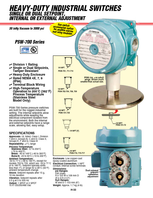
HEAVY-DUTY INDUSTRIAL SWITCHESSINgLE oR DUAL SETPoINT,PSW-700 SeriesDual external setpoint calibrationadjustment PSW-700 Series pressure switches are built for the rugged industrial setting. The internal setpoints allow adjustments while keeping the electrical component isolated from the environment. Both the internal and external setpoints have a range scale, allowing fast, easy setup.PSW-722, ±10 inH 2O range, shown much smaller than actual size.U Division 1 RatingU Single or Dual Setpoints, Tamper ResistantU Heavy-Duty Enclosure U Rated NEMA 4X, 7, 9 (IP66)U Terminal Block Wiring U High-TemperatureOperation to 200°C (392°F) Process Temperature (Stainless Steel Model Only)PSW-710, 715-7171/4 NPT1/4 NPT (F)PSW-731-7351/2 NPTPSW-702-704, 708, 709SPECIFICATIONSApprovals: UL listed; Class I, Division 1 and 2, Groups B, C and D; Class II, Groups E, F and G; Class III Repeatability: ±1% range Process Temperature:Stainless Steel: -57 to 204°C (-70 to 400°F)Brass: -40 to 149°C (-40 to 300°F) Buna-N: -23 to 93°C (-10 to 200°F)Ambient Temperature:-50 to 71°C (-58 to 160°F), except for models 703 to 705, which are -18 to 71°C (0 to 160°F). Setpoint typically shifts less than 1% of range for a 28°C (50°F) ambient temperature change.Shock: Setpoint repeats after 15 g, 10 ms durationVibration: Setpoint repeats after 2.5 g at 5 to 500 HzOutput: 1 SPDT or 2 SPDT 15 A 125/250/480 VacEnclosure: Low copper-cast epoxy-coated aluminumElectrical Connection: 3⁄4 NPT conduit; internal screw terminals Dimensions:psi Ranges:230 (max) H x 125 W x 108 mm D (9 x 4.9 x 4.3") H 2O Ranges:W and D = 153 mm (6") Weight: Approx. 1.7 kg (4 lb)PSW-721-72INDUSTRIAL SWITCHES PSW-707, 0 to 500 psirange, shown smallerthan actual size。
Z-Active 差分探头系列 P7313、P7380A、P7360A、P7340A 数据手册说明书

Z-Active™Differential Probe FamilyP7313•P7380A •P7360A •P7340A DataSheetFeatures &Bene fitsSignal Fidelity>12.5GHz Bandwidth (P7313,Typical)>8.0GHz Bandwidth (P7380A,Typical)>6.0GHz Bandwidth (P7360A,Typical)>4.0GHz Bandwidth (P7340A,Typical)Extended Linear Dynamic Range 1.25V p-p at 5x Attenuation (P7313)4V p-p at 25x Attenuation (P7313)2V p-p at 5x Attenuation (P7380A,P7360A,P7340A)5V p-p at 25x Attenuation (P7380A,P7360A,P7340A)Low Probe Loading DC Input Resistance 100k ΩDifferential 50k ΩSingle Ended AC LoadingZ min >200Ωout to 10GHz (P7313)Z min >290Ω,4GHz to 8GHz (P7380A,P7360A,P7340A)VersatilityMake Differential or Single-ended (Ground-referenced)Measurements*1Solder-down CapabilityHandheld Probing with Variable Spacing and Compliance Fixtured Probing Interchangeable Tip-Clip™Assemblies Connect to a Variety of Devices Economical TekConnect ®InterfaceApplicationsExamples Include,but are not Limited To:PCI-Express I and II,Serial ATA II,USB 2.0,DDRII,DDRIII,Fireware 1394b,Rambus,XAUI*1For details,please see application note 60W-18344-0,“Making Single-ended Measurements with DifferentialProbes.”1981Data SheetZ-Active™Probing Architecture Leads the Way for High-speed Probing Applications Tektronix has created a revolutionary Z-Active probe architecture that sets the industry benchmark for signalfidelity.Tektronix active probe architecture preserves high bandwidth while providing improved connectivity with low loading.The Z-Active architecture is a hybrid approach composed of a distributed attenuator topology feeding an active probe amplifier.The Z-Active probes use a tiny passive probe tip element that is separate from the amplifier,extending the usable reach of the probe.In traditional active probes,adding this much length can introduce signalfidelity problems.However this architecture maintains high DC input resistance and presents a higher AC impedance than previous probe architectures.It accomplishes this while providing significant length between the probe body and the probe attachment point to the DUT.This architecture provides the best of both worlds:high DC impedance like existing active probes and the stable high-frequency loading of Z0probes.Signal FidelityYou can be confident in the signalfidelity of your measurements because the Z-Active architecture provides:High BandwidthExcellent Step ResponseLow LoadingHigh CMRRExtended Linear Dynamic RangeExtended Linear Dynamic RangeMany of today’s logic signals and serial bus signals require the capabilityto measure up to several volts peak to peak.These voltage levels may easily be viewed with the Z-Active architecture probes(P7380A,P7360A, and P7340A)with the extended linear dynamic range.With a2.0V p-p linear dynamic input range at the5x attenuation setting,you can accurately measure DDR II and III,Firewire1394b,and PCI-Express I and II signals at reduced noise levels.In addition the25x attenuation setting’s linear dynamic input voltage range can be used up to5.0V p-p for accessing even larger signal swings found during transition times.ConnectivityThe Z-Active probe design allows the probe to easily switch between soldered,handheld,orfixtured applications.This family of probes uses Tip-Clip™assemblies,an interchangeable probe tip system that enables customers to configure their probe with the optimal tip for their application.These detachable assemblies make it possible to replace a tip for a fraction of the cost formerly associated with such hardware changes.The several lengths and variable spacing of the assemblies provideflexibility for adapting to vias and other test points of differing sizes.With Tektronix Tip-Clip assemblies,Monday’s solder-in probe can become Tuesday’s handheld tool,simply by switching tips. ValueThe combination of the Z-Active architecture and the Tip-Clip assemblies provide superior signalfidelity at a cost-effective price.The inexpensive Tip-Clip assemblies enable full-performance solder connections at a very low price per connection.Over the life of a probe this can add up to significant savings in the cost of operation.Performance You Can Count OnDepend on Tektronix to provide you with performance you can count on.In addition to industry-leading service and support,this product comes backed by a one-year warranty as standard.Z-Active™Differential Probe Family—P7313•P7380A•P7360A•P7340ACharacteristicsCharacteristic P7340A P7360A P7380A P7313Bandwidth(Typical)>4GHz>6GHz>8GHz>12.5GHzRise Time(10%-90%)(Guaranteed)<100ps<70ps<55ps<40psRise Time(20%-80%)(Typical)<70ps<50ps<35ps<25psAttenuation5x or25x,user selectableDifferential Input Range±1.0V(5x)±2.5V(25x)±0.625V(5x)±2.0V(25x)Linearity Error for Differential Input Dynamic Range(Typical)±0.5%for-0.5V to+0.5V(5x)±1.0%for-0.75V to+0.75V(5x)±2.0%for-1.0V to+1.0V(5x)±0.5%for-1.5V to+1.5V(25x)±1.0%for-2.5V to+2.5V(25x)±2.0%for-3.0V to+3.0V(25x)±0.25%for-0.5V to+0.5V(5x)±0.75%for-0.625V to+0.625V(5x)±0.5%for-1.6V to+1.6V(25x)±1.0%for-2.0V to+2.0V(25x)Operating Voltage Window+5.0V to-3.0V+4.0V to-3.0V Offset Voltage Range+4.0V to-3.0VDC Input Resistance100kΩAC Loading(Differential Z min)>290Ω>200ΩNoise<31nV/√Hz(5x)<75nV/√Hz(25x)CMRR>50dB at1MHz>35dB at1GHz>20dB at4GHz >50dB at1MHz>35dB at1GHz>20dB at6GHz>50dB at1MHz>35dB at1GHz>20dB at8GHz>50dB at1MHz>35dB at1GHz>20dB at6GHz>15dB at12.5GHzNondestructive Input Range±15VInterface TekConnect®Cable Length 1.5m 1.5m 1.2m 1.2m Ordering InformationP7313>12.5GHz Z-Active Differential Probe for TekConnect®Interface. P7380A>8.0GHz Z-Active Differential Probe for TekConnect®Interface.P7360A>6.0GHz Z-Active Differential Probe for TekConnect®Interface.P7340A>4.0GHz Z-Active Differential Probe for TekConnect®Interface.All Include:One-year warranty,plus see Standard Accessories table.3Data SheetStandard AccessoriesDescriptionP7340AP7360AP7380AP7313Reorder Part NumberPouch,Nylon Carrying Case with Inserts1each 1each 1each 1each 016-1952-xx Qty 1Accessory Performance Summary and Reorder Sheet1each 1each 1each 1each 001-1389-xx Qty 1020-2640-xx Qty 1–Opt.L0020-2648-xx Qty 1–Opt.L5User Manual -Printed.Includes Reply Card and CD 1each1each1each1each040-2649-xx Qty 1–Opt.L7BNC (M)-to-Minigrabber Adapter 1each 1each 1each 1each 013-0342-xx Qty 1Anti-static Wrist Strap 1each 1each 1each 1each 006-3415-xx Qty 1Magnifying Glasses 1each 1each 1each 1each 378-0486-xx Qty 1Calibration Data Report 1each 1each 1each 1each Opt.D1Handheld Probe Adapter 1each 1each 1each1each 015-0717-xx 1eachP7313:020-2636-xx 1eachP7380A:020-2557-xx 1eachP7360A:020-2690-xx Accessory Box and Contents1each P7340A:020-2690-xx Attachment Kit1each 1each 1each 1each 016-1953-xx Qty 1Velcro Fastening Strap 10each 10each 10each 10each –Velcro Fastening Dots 10each 10each 10each 10each –Adhesive Tip-Clip Tape*2(Strip of 10)3each 3each 3each 3each –Color Band Kit (2ea.of 5colors)1each 1each 1each 1each 016-1948-xx Qty 1Short Flex,Small Resistor Tip-Clip Assembly 2each 2each 3each 3each 020-2600-xx Qty 10Medium Flex,Small Resistor Tip-Clip Assembly 2each 2each 3each 3each 020-2602-xx Qty 10Long Flex,Small Resistor Tip-Clip Assembly 2each 2each 3each 3each 020-2604-xx Qty 10Variable Spacing Tip-Clip Kit 3each 3each 3each 3each 020-2596-xx (Kit of 3)Square Pin Adapter Tip-Clip 1each 1each 1each 1each 020-2701-xx (Kit of 3)Tip-Clip Ejector*23each 3each 3each 3each –020-2639-xx Qty 10HBW Straight Flex Tip-Clip Assembly –––3each020-2657-xx Qty 5020-2638-xx Qty 10HBW Right-Angle Flex Tip-Clip Assembly –––3each 020-2656-xx Qty 5Wire Replacement Kit–––1each 020-2644-xx Qty 1Short Flex,Large Resistor 1/8W Tip-Clip Assembly––3each –020-2601-xx Qty 10Long Flex,Large Resistor 1/8W Tip-Clip Assembly––3each –020-2605-xx Qty 10Medium Flex,Large Resistor 1/8W Tip-Clip Assembly2each2each3each–020-2603-xx Qty 10*2Tip-Clip Ejectors and Tip-Clip Tape are shipped standard with the 020-xxxx-xx Tip-Clip Assembly Kits.Recommended AccessoriesDescriptionP7360P7380P7313Part NumberProbe Positioner Yes Yes Yes PPM100Probe PositionerYes Yes Yes PPM203B PPM203B,PPM100Adapter Fixture Yes Yes Yes 013-0339-xx P7340A:067-0419-xx P7360A:067-0419-xx P7380A:067-0419-xx Calibration Fixture Yes Yes YesP7313:067-1616-xxDSA8200Series TekConnect ®Probe Interface Yes Yes Yes 80A03Deskew FixtureYes Yes Yes 067-1586-xx Real-time Spectrum Analyzer TekConnect Probe AdapterYes Yes YesRTPA2AZ-Active™Differential Probe Family—P7313•P7380A•P7360A•P7340AService OptionsOpt.CA1–Single Calibration or Functional Verification.Opt.C3–Calibration Service3Years.Opt.C5–Calibration Service5Years.Opt.D3–Calibration Data Report3Years(with Opt.C3).Opt.D5–Calibration Data Report5Years(with Opt.C5).Opt.G3–Complete Care3Years(includes loaner,scheduled calibration and more). P7360A,P7380A onlyOpt.G5–Complete Care5Years(includes loaner,scheduled calibration and more). P7360A,P7380A onlyOpt.R3–Repair Service3Years.Opt.R5–Repair Service5Years.Language OptionsOpt.L0–English Manual.Opt.L5–Japanese Manual.Opt.L7–Simplified Chinese Manual.Additional Service Products Available During Warranty (DW)or Post Warranty(PW)P7313-CA1–Single Calibration or Functional Verification.P7313-R1PW–Repair Service Coverage1-year Post Warranty.P7313-R2PW–Repair Service Coverage2-year Post Warranty.P7313-R3DW–Repair Service Coverage3Years(includes product warranty period); 3-year period starts at time of customer instrument purchase.P7313-R5DW–Repair Service Coverage5Years(includes product warranty period); 5-year period starts at time of customer instrument purchase.P7340A-CA1–Single Calibration or Functional Verification.P7340A-R1PW–Repair Service Coverage1-year Post Warranty.P7340A-R2PW–Repair Service Coverage2-year Post Warranty.P7340A-R3DW–Repair Service Coverage3Years(includes product warranty period);3-year period starts at time of customer instrument purchase.P7340A-R5DW–Repair Service Coverage5Years(includes product warranty period);5-year period starts at time of customer instrument purchase.P7360A-CA1–Single Calibration or Functional Verification.P7360A-R1PW–Repair Service Coverage1-year Post Warranty.P7360A-R2PW–Repair Service Coverage2-year Post Warranty.P7360A-R3DW–Repair Service Coverage3Years(includes product warranty period);3-year period starts at time of customer instrument purchase.P7360A-R5DW–Repair Service Coverage5Years(includes product warranty period);5-year period starts at time of customer instrument purchase.P7380A-CA1–Single Calibration or Functional Verification.P7380A-R1PW–Repair Service Coverage1-year Post Warranty.P7380A-R2PW–Repair Service Coverage2-year Post Warranty.P7380A-R3DW–Repair Service Coverage3Years(includes product warranty period);3-year period starts at time of customer instrument purchase.P7380A-R5DW–Repair Service Coverage5Years(includes product warranty period);5-year period starts at time of customer instrumentpurchase.Tektronix is registered to ISO9001and ISO14001by SRI Quality SystemRegistrar.Product(s)complies with IEEE Standard488.1-1987,RS-232-C,and with TektronixStandard Codes and Formats.5Data SheetZ-Active™Differential Probe Family—P7313•P7380A•P7360A•P7340A7Data Sheet Contact Tektronix:ASEAN/Australasia(65)63563900Austria0080022554835*Balkans,Israel,South Africa and other ISE Countries+41526753777Belgium0080022554835*Brazil+55(11)37597627Canada180********Central East Europe and the Baltics+41526753777Central Europe&Greece+41526753777Denmark+4580881401Finland+41526753777France0080022554835*Germany0080022554835*Hong Kong4008205835India0008006501835Italy0080022554835*Japan81(3)67143010Luxembourg+41526753777Mexico,Central/South America&Caribbean52(55)56045090Middle East,Asia,and North Africa+41526753777The Netherlands0080022554835*Norway80016098People’s Republic of China4008205835Poland+41526753777Portugal800812370Republic of Korea00180082552835Russia&CIS+7(495)7484900South Africa+41526753777Spain0080022554835*Sweden0080022554835*Switzerland0080022554835*Taiwan886(2)27229622United Kingdom&Ireland0080022554835*USA180*********European toll-free number.If not accessible,call:+41526753777Updated10February2011For Further Information.Tektronix maintains a comprehensive,constantly expandingcollection of application notes,technical briefs and other resources to help engineers workingon the cutting edge of technology.Please visit Copyright©Tektronix,Inc.All rights reserved.Tektronix products are covered by U.S.and foreign patents,issued and rmation in this publication supersedes that in all previously published material.Specification and price change privileges reserved.TEKTRONIX and TEK are registered trademarks ofTektronix,Inc.All other trade names referenced are the service marks,trademarks,or registered trademarksof their respective companies.02Oct201151W-17891-12。
74AUP1G32中文资料

[1] H = HIGH voltage level; L = LOW voltage level.
9. Limiting values
Output Y L H H H
Table 6: Limiting values In accordance with the Absolute Maximum Rating System (IEC 60134). Voltages are referenced to GND (ground = 0 V).
Table 4: Symbol
B A GND Y n.c. VCC
Pin description Pin TSSOP5 1 2 3 4 5
XSON6 1 2 3 4 5 6
32
B1
6 VCC
A2
5 n.c.
GND 3
4Y
001aab641 Transparent top view
Fig 5. Pin configuration SOT886 (XSON6)
5. Marking
Table 3: Marking Type number 74AUP1G32GW 74AUP1G32GM
Marking code pG pG
9397 750 14678
Product data sheet
Rev. 01 — 2 August 2005
© Koninklijke Philips Electronics N.V. 2005. All rights reserved.
Description
data input B data input A ground (0 V) data output Y not connected supply voltage
用友NMC使用说明
第四章:OverView ......................................................................................................... 16
单机的部署 ....................................................................................... 8 集群的部署 ....................................................................................... 8 Was启用安全管理............................................................................. 9 服务器端主要的配置文件 ................................................................ 9 服务器端部署的几个注意事项....................................................... 11 NMC客户端的获取.......................................................................... 12 启动客户端 ..................................................................................... 12 客户端使用的几种模式 .................................................................. 12 利用邮件传输协议进行远程监控................................................... 13 客户端主要的配置文件 .................................................................. 14 第二部分:实时监控............................................................................................................ 15
TPS75301QPWP中文资料

TPS75101Q, TPS75115Q, TPS75118Q, TPS75125Q, TPS75133Q WITH POWER GOOD TPS75301Q, TPS75315Q, TPS75318Q, TPS75325Q, TPS75333Q WITH RESET FAST-TRANSIENT-RESPONSE 1.5-A LOW-DROPOUT VOLTAGE REGULATORS
PWP PACKAGE (TOP VIEW)
GND/HEATSINK NC IN IN EN PG or RESET† FB/SENSE OUTPUT OUTPUT GND/HEATSINK
1 2 3 4 5 6 7 8 9 10
20 19 18 17 16 15 14 13 12 11
GND/HEATSINK NC NC GND NC NC NC NC NC GND/HEATSINK
IL=1.5 A CL=100 µF (Tantalum) VO=1.5 V
250 VDO – Dropout Voltage – mV
200
IO = 1.5 A
150
100 IO = 0.5 A 50
0 –40
10
60
110
160
0 0 1 2 3 5 6 t – Time – ms 7 8 9 10
SLVS241B – MARCH 2000 – REVISED JUNE 2003
NOTE: The TPS75x01 is programmable using an external resistor divider (see application information). The PWP package is available taped and reeled. Add an R suffix to the device type (e.g., TPS75201QPWPR) to indicate tape and reel. 3 4 IN 0.22 µF 5 EN GND 17 OUT PG or RESET SENSE OUT 6 7 8 9 + CO † 47 µF VO
SulzerTextilP730...

Your success is our futureSulzer Textil P7300hp Projectile Weaving Machine –Top performance and versatility in fabric production22000-02022002-01462000-0138The P7300hp high-performance projectile weaving machine: increase your competitive advantageWith the Sulzer TextilP7300hp you can fulfil your customers’ varyingrequirements precisely and individually. The mature projectile weft insertion technology is suitable for any weft material: spun yarns made of natural and manmade fibres, filaments,The P7300hp is a high-performance, all-purpose projectile weaving machine. Compared to the proven P7300, its performance is up to twenty per cent higher. Optimized motion sequences and direct projectile acceleration with thrust shoe result in a maximum weft insertion rate of 1570 m/min.or tapes. Whether weaving them to simple standard fabrics, fashion materials or wide, heavy technical textiles, the P7300hp is in its element.For decades, projectile weav-ing machines have been used to produce countless technical textiles, from the finest filter fabrics to densely woven and tear-resistant special fabrics for balloons and even ultra-heavycoating fabrics – all in out-standing quality.Denim fabrics are produced worldwide and withgreat success on projectile weaving machines. In the production of fabrics from polypropylene tapes, for Big Bags,geotextiles or agrotextiles,the projectile weaving machine excels withunparalleled economy andquality.32001-00809094-0161Cost-efficient and geared to your needsThe perfect interaction of a technologically mature design and cutting-edge computer technology puts the P7300hp in a class of its own. Its versatility and fast adaptability make it your company’s new success factor.Curtains and drapes inlarge widths can be woven best and most easily on the P7300hp .You can only gain from the multi-facetted benefits of the P7300hp :•lowest specific power consumption of all weaving systems•tucked selvedges withoutcostly raw material wastage•quick warp and style changing •low spare parts consumption and low-maintenance operation•super-easy operation combined with high reliability•oil bath-immersed,practically maintenance-free sub-units.The P7300hp combines top productivity – thanks to quick style changing, easy programming and high speed – with outstanding reliability.On models with large working widths, its efficien-cy is further increased by its ability to weave several fabric runs of the same or different widths simultane-ously. As a result, the maxi-mum weft insertion rate is attained at low machine rpm. That reduces machine wear and building stresses,lowers space requirementsand helps save electricity.42004-00542002-00982004-0103Projectile weft insertion –reliable and controlledThe weft is guided in a controlled manner in every phase of weft insertion: from weft transfer to the projectile, through insertion into the shed, to beat-up.Worldwide, there are mil-lions of projectiles in operation 24 hours a day The projectiles grip reliably a wide variety of threads,tapes or monofilaments and insert them in the shed.Reflecting the varying requirements for different weft yarns, projectile grip-pers with various clamping forces and surface areas are available. One outstand-ing feature of projectile technology is that the weft is inserted without central transfer, i.e. withoutadditional acceleration and braking. With this unique insertion technology,the P7300hp inserts all weft yarns in a controlled manner and with lowyarn strain, thus helping to ensure maximum reliability in the production of quality fabrics.The picking lever with the thrust shoe for directacceleration plays a key role in achieving the high weft insertion rate.The electronic warp let-off control guarantees constant warp tension frombeginning to end of the warp.Optionally, the P7300hp projectile weaving machine can be equipped with a control system for two, four or six weft colours.Unique weaving widths up to 540 cmThe P7300hp is available in nine working widths, from 190 cm to 540 cm. It is the only weaving machine for which 540 cm is a standard width. This has crucial advantages in the produc-tion of technical textiles.For instance, it enables agro- and geotextiles to be produced in large widths so that fewer seams are required.Minimizing yarn wastage –every selvedge the way you need itIn both single- and multi-panel weaving, everyselvedge can be tucked by standard or intermediate tucking units. The width of the tucked selvedges can be set from 18 to 25 mm and even to 35 mm. Accurate weft length measurement ensures that there is no yarn wastage. Instead of tucking units, the P7300hp can be equipped with devices for producing leno or melted selvedges. In the case of leno selvedges the Selvedge Saver eliminates auxiliary selvedges, thus economizing warp and weft yarn – a saving thattranslates into hard cash.52001-00572004-0072No compromises on fabric qualityIn developing the P7300hp , top fabric quality was our paramount goal. We achieved it with a new shed geometry.Premium fabrics,flawless qualityThe interplay of shed for-mation and warp and weft run is crucial for a flawless appearance of the cloth. In the P7300hp this principle has beenconsistently applied. By entering just a few data at the terminal, the cloth take-up, shed levelling and warp let-off are optimally coordinated. In this waysensor systems. A variety of back rest roller and cloth take-up systems are avail-able to suit the density and type of the fabric being woven. The weft density is adjustable in steps of 0.1pick per cm.No limits to fabric patterning A tappet motion with up to 14 heald shafts or an elec-tronically controlled dobby for a maximum of 18 heald shafts can be fitted for shed formation.In combination with the colour selector, which can handle up to 6 weft colours,there are practically no re-strictions on the designer's imagination.Perfect control of warptension is achieved with the new force sensors on the fabric support, where fabric quality is decided. Thisconfiguration is suitable for both warp tensioner and whip roller systems.A cloth take-up with a take-up and press roller isstandard equipment on the P7300hp . The floating take-up roller (photo) ensures reliable take-up even of heavy fabrics.starting marks are reliably and effectively avoided,even with delicate fabrics.Warp let-off and clothtakeup are electronicallycontrolled. With wideweaving machines or when using two half warp beamsthe machine is equippedwith two warp let-offdevices. The warp tensionof each warp let-off iscontrolled by separate624-6Projectile technology for top resultsGeared to the future, with mature mechanical systems and the latest computer technology, the P7300hp fulfils the requirements of today’s and tomorrow’s weaving rooms.The P7300hp helps ensure high productivity, user-friendly operation and high fabric quality. The machine’s modular design means that it can be adapted to meet future needs at any time. So even in the long term it remains a sound invest-ment.79099-0065The Sulzer Textil P7300hp produces fabrics in supreme quality, from all raw materials and for all applications.With a weft insertion rate of up to 1570 m/min it isoutstandingly cost-efficient.82004-00102001-00162001-00562003-0077The weaving machine for tomorrow’s needsThe versatility of the P7300hp is clear – in itsequipment and in the many optional extras available.With accessories tailored to the application it can be customized to meet your exact needs.With the P7300hp you are investing in a future-oriented, upgradeableweaving system. Thanks to its modular design, the machine can be adapted at low cost to meet new requirements. Thus it is a machine that can “grow”with your customers’ needs.Expanding the colourselector from two to four or even six weft colours is just as simple as switch-ing from tappet motion to dobby for shed formation.With the new machine-coupled pick findingfunction, operation of the weaving machine has been substantially improved.The P7300hp can be equip-ped with tappet motions for four to 14 heald shafts.The built-in levelling device facilitates operation.Whether equipped with a dobby for up to 18 shafts or a tappet motion for up to 14shafts, setting of the shed isquick and easy.92004-0080The P7300hp fulfils thehighest quality standards in the production of high-quality jacquard fabrics.Maintenance costs minimized –benefit maximizedIn servicing and mainte-nance, the P7300hp sets new standards. Substan-tially longer servicing and oil change intervals reflect the machine’s outstanding reliability and cost-efficiency. The reduced number of different lubri-cants saves costs through simplified logistics. All joints in the shaft drive have permanently lubri-cated ball bearings.The lifting levers are lubri-cated with grease. The new casing prevents accumu-lation of dust and is easy toLow-maintenance shaft drives with permanently lubricated ball bearingsbring an additional benefit –high flexibility for quick and easy style changes.clean. Practical mechanical and electronic safety com-ponents provide maximum protection for operatingpersonnel.1020040-07520040-07620040-0772004-0095-1Integration in networks to optimize the weaving processCorporate integration in local and global networks is also a major challenge in the textile industry.Sultex’s answer: state-of-the-art control systems architecture in its weaving machines.Reacting and supplying fast while maintaining high fabric quality are theessential preconditions for gaining advantages in the marketplace. In order to satisfy these demanding criteria the new projectile weaving machine has been equipped with a ground-breaking weaving machine control system.In the P7300hp , latest-generation microprocessors control, monitor and regu-late all major machine functions, thus ensuring consistently high quality in the weaving process.A touch-screen terminal is the clear, user-friendly man-machine interface.This user interface is based on Internet browsertechnology: the P7300hp thus anticipates the future of the textile industry.They include:•automatic adjustment of the weft detector•optimal adjustment of the projectile brake•semi-automatic warppull-through with synchronized drives•extended statistical functions •simple, accurate diagnoses•additional help functions.Besides machineparameters and pattern data which can be pro-grammed at the terminal or transferred viaproduction management systems and memory cards,statistical, help and diagnosis functions are available to simplify operation.Maximum user-friendliness and pioneering browser technology – twocharacteristic features of the terminal on the newprojectile weaving machine.Thanks to ergonomically arranged keys with clear,easy-to-understand symbols,operation of the P7300hpis simplicity itself.112004-0074-13World-class weaving machines –worldwide after sales service tailored to your needsProject consultingIf desired, our experts will draw up plans for optimal positioning of your weaving machines, and advise you on the modernization of an existing production facility or the planning of a new one.Production economics Our broad-basedknowledge of weaving processes is a safe founda-tion for investment and profitability analyses on any scale. The results are a dependable guide for rational investment decisions reflecting a genuine need.Weaving trialsOur Textile Centres inSwitzerland, Japan and the USA make the large body of weaving knowledge ob-tained from research,development and pro-cessing available to you.At Sultex, you can test any yarn on any machine you want. The results will guide you to the most suitable weaving system.Training Correct training is crucial for optimal utilization of our weaving systems. We train your operating personnel on the spot at your facility, in special courses at Sultex, or at one of the training centres we operate around the world.Besides the basic courses we offer, we can collaborate with you to develop training concepts to suit your organization or to meet other specific puter Based Training Sultex’s Computer Based Training is the key to independent, on-the-spot basic and further training.Based on the “learning on the job” principle, it teaches how to carry out settings,adjustments and checks, via clear, easy-to-understand videos, animations and illustrations.With regard to both content and method the course is professionally designed and makes learning a pleasure.AVANTI services / Textile Technical Consulting Increase the efficiency of your weaving mill and strengthen your position in the market. Sultex can assist you by running and maintaining your facility for you, partially or completely.Tailor-made options are available for the entire production process from warping to weaving, on request with guarantees according to your requirements.Our experts from Textile Technical Consulting can provide professional support in developing new fabrics and optimizing entire production processes.In this way you can achieve optimal fabric quality and ensure maximum cost-efficiency for your facility.Customer Support Services Supplying you quickly and reliably with spare parts,components andaccessories is one of the most important servicesoffered by Sultex. With “ELSPACEnet” (Electronic Spare Part Catalogue via Internet) and “EDOSnet”(Electronic Direct Ordering System via Internet), our spare parts logistics are continuously adapted to customers’ and market requirements, thus ensuring fast,comprehensive availability and supply.Upgrading Thanks to their modular design, our weavingmachines can be upgradedat any time to meet changing market require-ments. Our specialists will be glad to advise you.Based on close customer contacts, Sultex ensures that support for its partners and customers continues after they purchase their weaving machines. Sultex service is not limited to merely commissioning the machines. It also ensures that they remain fully functional and available throughout their service lives, to give the usercomplete satisfaction.Your success is our future24-19-2995-984PrintedinSwitzerlande/35.6.9BodSultex LimitedHead OfficeCH-8630 Ruti ZH, SwitzerlandPhone+41 (0)55 250 21 21Fax+41 (0)55 250 21 01******************Outstanding featuresof the Sulzer Textil P7300hp:•uncompromisingimplementation of customers’requirements•high flexibility for rapid responseto changing market trends•logical technological concept forexcellent fabric quality•designed for exceptionally cost-efficient production of a broad range of fabrics•low operating costs thanks to low service requirement.Specifications subject tochange without notice.。
- 1、下载文档前请自行甄别文档内容的完整性,平台不提供额外的编辑、内容补充、找答案等附加服务。
- 2、"仅部分预览"的文档,不可在线预览部分如存在完整性等问题,可反馈申请退款(可完整预览的文档不适用该条件!)。
- 3、如文档侵犯您的权益,请联系客服反馈,我们会尽快为您处理(人工客服工作时间:9:00-18:30)。
I S 产 业总计  ̄ I pJ 印刷 业 制版 业 装订 业 F ¥I 加工 业 p1 品
12O 3O 158 02 79 6 70 8 98 8
94 14 67 93 58 5 75 7 74 6
35 57 23 70 28 6 21 9 23 3
1 8 58 14 24 17 2 13 3 6 7
企 业 有 4 2 ,仅 占 E本 印 刷 企 业 5家 t
总数 的15 . %,而 l 人 3 4~9 ~3 1 3 人
的 企 业 则 达 到 2 3 4 , 占总 数 的 24家 7 3 5. %。小 型 企 业 比 例大 的 特 点 ,
附表 2 0 年 日本 印刷产业不 同规模 ( 08 按职 工人数划分 )企业数量
印刷相 关服 务业
15 3
7 4
3 5
1 7
4
5
1
1
22 7
宏观数据小窗 口:P I M 连续 1 个月高于 “ 8 扩张点”
国 家 统 计 局 、 中 国 物 流 与 采 购联合会9 1 月 日发 布 报 告 ,8 月份 P MI( 国制造 业 采 购 经理 指 数 ) 中 为 5 . %,在 连 续 三个 月 回落 下 滑 17 后 再 度 出现 回升 ,较 上 月升 0. 个 5 月份 未来 不会 大幅度 回落 。中金 公司则在 月外 围风险加 大的影响还没有在8 MI MI 9 日 布的报告 中指出 ,8 ̄ MI 月1 发 )P 出 P 中反映出来 ,把P 的反弹作为经 现季 节性 反弹符 合预 期 ,但 未来几 个 济放缓 已经结束的证据还为时过早。
百 分 点 。虽 然这 一指 数 已持 续 1个 8 月保 持 在 5 % 反 映 经 济 总 体 扩 张 ) 0 (
以上 ,但 此 前 三个 月连 续 回落 。与 P 指 数走 势 一 致 ,投 资 、工业 等 MI 数据 也 出现 增 速放 缓的 情况 。 国务院发展研究中心分析指 出, P } 数 小幅 回升预示 中国经济不会 MIR 出现深度 回调 。从支持经济增长需求 因素看 ,今年 以来 外 贸 出 口强 劲恢 复 ,消 费 增长 大体 平 稳 ,投 资 增速
有所 回落 ,但增长 水平仍 然在2 %以 0
上 ,受这些 因素支持 ,中国经济增长
1 印刷 经理 人 Pi i ngr2 1 / 8 r t gMaae 0 09 nn
科 印传媒 四刊杂 志 ,火热征 订 中 O O 8 2 5 0 / 5 1 一 8 7 7 3 0
另 外 , 根 据 2 0 日本 经 济 0l 年 产业 省发 布的统 计数 据显 示 , 日 本 印刷 产 业 企 业 数 量 占 日本 制 造 业 的全 部 企业 数 量 的 比例 :2 0 年 04 为6. %,2 0 ~2 0 年 为 6 8 9 0 5 07 . %, 2 0 年 降为6 7 09 .%
97 3 76 8 7 3 4 9 2 5
86 0 64 61 6 6
5 5 5 1 2 1
4 3 3 7 2 2 1
2 0 2 0
6 3 2 1
264 98 23 1 3 1 1 0 91 29 02 2O 18
V iw 视 点 l 讯 e 资
数 据 库
小 型 企 业 占 日本 印 刷 产 业 企 业 总 数 的7 .% 53
小 型 印 刷 企 业 数 量 众 多 ,是 日本 印刷 产业 的 一 大特 点 。2 1 年 00 日本 经济 产 业省 发 布 的 统计 数 据 显 示 ,2 0 年 职 工 超 过 1 0 的 印 刷 08 0人 在 日本 印 刷产 业 的 各个 业 种 中表 现
不到 1 6  ̄ 6 OL日元 ,前 者 是后 者 的两 倍多 。
得都 很显 著 。
从销 售 额 来 看 ,小企 业 数 量 虽 多 ,但 其 销 售额 却 远 不 能与 数 量极 少 的大 企 业 相 比 。数据 显示 , 日本 职 工 超 过 1 0 人 的 印 刷 企 业 只有 6 00 家 ,销 售 额 却有 3 6  ̄ 9 0L日元 之 多 ; 而 l 2 0 微 小企 业 的销 售 额仅 为 0家 3