Channel Modeling for Terrestrial Free Space Optical Links
测绘专业英语翻译27单元
unit 27 Developments of Photogrammetry摄影测量的发展Photogrammetry can be defined as the art, science, and technology of obtaining reliable information about physical objects and the environment by recording,measuring and interpreting photographic images (American Society for Photogrammetry and Remote Sensing 1987).(摄影测量可以定义为通过记录、量测和解读相片来获取关于物理实体及环境的可靠信息的科学和技艺。
)Photogrammetry is the technique of measuring objects (2D or 3D) from photographs, but it may be also imagery stored electronically on tape or disk taken by video or CCD cameras or radiation sensors such as scanners.(摄影测量是在相片上量测物体(二维或三维),但也可能是通过电子手段【electronically】存储在磁带上或摄像机、CCD相机或像扫描仪一样的辐射传感器自带的盘上的图像。
)The most important feature of photogrammetry is that the objects are measured without being touched.(摄影测量最重要的特征是物体不经过接触就可量测。
)Although the term Photogrammetry can apply to measurements from ground photographs, modern photogrammetric techniques are most often applied to aerial and satellite images.(尽管摄影测量这个词能应用于对地面相片的量测,现代摄影测量技术更常常用于航空和卫星图像。
点云数据转换成实体模型通过基于点的立体像素化立体像素

点云数据转换成实体模型通过基于点的立体像素化立体像素PointCloudDataConversionintoSolidModelsviaPoint-BasedVoxelization1 2 3 4Tommy Hinks ; Hamish Carr ; Linh Truong-Hong ; and Debra F. Laefer, M.ASCEAbstract:Automatedconversionofpointclouddatafromlaserscanninginto formatsappropriateforstructuralengineeringholdsgreatprom- iseforexploitingincreasinglyavailableaeriallyandterrestriallybase dpixelizeddataforawiderangeofsurveying-relatedapplicationsfrom environmental modeling to disaster management. This paper introduces a point-based voxelization method to automatically transform pointclouddataintosolidmodelsforcomputationalmodeling.Thefundamentalvi abilityofthetechniqueisvisuallydemonstratedforbothaerial andterrestrialdata.Foraerialandterrestrialdata,thiswasachievedinl essthan30sfordatasetsupto650,000points.Inallcases,thesolid models converged without any user intervention when processed in a commercial ?nite-element method program. DOI: 10.1061/ASCESU.1943-5428.0000097 2013 American Society of Civil Engineers.CE Database subject headings: Data processing; Surveys; Finite element method; Information management.Author keywords: Terrestrial; Aerial; Laser scanning; LiDAR; Voxelization; Computational modeling; Solid models; Finite element.Introductionexist.Thispaperlaysthegroundworkforkeyadvancementinsucha pipeline. The procedure proposed herein to reconstruct buildingLaser scanning has achieved great prominence within the civil en- facadesfrompointcloud,whichisafundamentalstepforgenerating gineering community in recent years for topics as divergent as city-scale computational models.coastline monitoring Olsen et al. 2009, 2011, airport layout op- timization Parrish and Nowak 2009, and ground-displacementidenti?cation for water-system risk assessment Stewart et al.FacadeReconstruction2009. Additionally, there has been strong motivation to obtainfurther functionality from laser scanning and other remote-sensing Inrecentyears,developmentsinlaser-scanningtechnologyand?ight-data, including three-dimensional 3D volume estimation forpath planning have allowed aerial laser scanning ALS to acquire mining Mukherji 2012, road documentation Dong et al. 2007,pointclouddataquicklyandaccuratelyatacityscale,therebyhaving structuralidenti?cationShanandLee2005;Zhangetal.2012,and thepotentialforreconstructing3Dbuildingsurfacesacrossanentire emergency planning Laefer and Pradhan 2006. Furthermore,city in nearly real time. A number of approaches based on semi- computational responses of city-scale building groups are increas- automaticLangandForstner1996andautomaticHenricssonetal. inglyindemandforheightenedurbanization,disastermanagement,1996techniqueshavebeenproposedtoreconstructbuildingmodelsand microclimate modeling, but input data are typically too ex- from such data sets, but automatically extracting highly detailed, pensive as a result of the need for manual surveying. Additionally, accurate,andcomplexbuildingsstillremainsachallengeHaalaandcurrent software tools for transforming remote-sensing data into Kada 2010. The semiautomatic procedures need human operator computationalmodelshaveoneormoreofthefollowingproblems: intelligence.TheautomaticvisualmodelingofurbanareasfromALS alowdegreeofreliability,aninabilitytocapturepotentiallycritical data tends to extract sample points for an individual building by details,and/oraneedforahighdegreeofhumaninteraction.Todate, applying segmentation techniques and then reconstructing eacha seamless, automated, and robust transformation pipeline frombuilding individually. In such cases, vertical facade surfaces are notremote-sensing data into city-scale computational models does not portrayed in detail, and outlines may be of relatively low accuracy unless ground planes are integrated, which requires either a priori1 informationormanualintervention.Unfortunately,theeffectivenessDoctoralRecipient,SchoolofComputerScienceandInformatics,Univ.of engineering modeling often depends largely on the geometricCollege Dublin, Bel?eld, Dublin 4, Ireland. E-mail: ******************2accuracy and details of the building models?thus the currentSeniorLecturer,SchoolofComputing,FacultyofEngineering,Univ.ofmismatch.Leeds, Leeds LS2 9JT, U.K. E-mail: h.carr@//0>.3Post-doctoral Researcher, Urban Modelling Group, School of Civil, Presently, commercial products are generally semiautomatic StructuralandEnvironmentalEngineering,Univ.CollegeDublin,Bel?eld, Laefer et al. 2011, whereas in the computer graphics and photo- Dublin 4, Ireland. E-mail: linh.truonghong@gmailgrammetry communities, researchers have focused on automated4AssociateProfessor,LeadPI,UrbanModellingGroup,SchoolofCivil,surfacereconstructionfromdenseandregularsamplepointsHoppeStructuralandEnvironmentalEngineering,Univ.CollegeDublin,Bel?eld, 1994; Kazhdan et al. 2006. Unfortunately, ALS data are oftenDublin 4, Ireland corresponding author. E-mail: ******************* sparse and irregular, and may contain major occlusions on vertical Note.ThismanuscriptwassubmittedonNovember16,2011; approvedsurfaces owing to street- and self-shadowing Hinks et al. 2009.on September 10, 2012; published online on September 13, 2012. Discus- Dedicated urban modeling surface-reconstruction approachession period open until October 1, 2013; separate discussions must be generallyusethemajorbuildingplanesChenandChen2007andsubmitted for individual papers. This paper is part of the Journal ofcan be described as either model-driven or data-driven. Model-Surveying Engineering, Vol. 139, No. 2, May 1, 2013ASCE, ISSN0733-9453/2013/2-72?83/$25.00. driven techniques use a ?xed set of geometric primitives that are72 / JOURNALOFSURVEYINGENGINEERING?ASCE / MAY2013J. Surv. Eng. 2013.139:72-83.Downloaded from by East China Inst of Tech on 04/13/13.Copyright ASCE. For personal use only; all rights reserved.Fig. 1. Work?ow of the proposed approach: *Collection and preparation of LiDAR data involve multiple steps outside the scope of this paper’s scienti?ccontribution;thesegenerallyincludeplanning,collection,re gistration,and?ltering;seeTruong-Hong2011andHinks2011forfurther detailsttedtothepointdata.Suchtechniquescanbeeffectivewhenadataset is sparse because the ?tting of geometric primitives does not require complete data. In contrast, data-driven techniques derive surfaces directly from the point data and are capable of modeling arbitrarilyshapedbuildings.Generally,data-drivenapproachesaremore?exiblethanmodel-drivenapproaches,butareoftensensitiveto noise in the input data.For strictly visual representation, model-driven approachescanbeeffective.Forexample,Haalaetal.1998 proposed four dif-ferent primitives and their combinations to automatically derive 3D building geometry of houses from ALS and existing ground planes.Similarly, Maas and Vosselman 1999 introduced an invariantmoment-basedalgorithmfortheparametersofastandardgabled-roofhouse type that allowed for modeling asymmetric elements such as dormers. However, these efforts assume homogeneous point dis-Fig. 2. Octree representationtributions, which is unrealistic. You et al. 2003 also adapted a set of geometric primitives and ?tting strategies to model complex buildings with irregular shapes, but the approach required user interventionandgeneratedonlylimitedwalldetails.Huetal.2004used a combination of linear and nonlinear ?tting primitives to SolidModelingreconstructacomplexbuilding,inwhichaerialimagerywasusedtore?ne the models. To generate building models directly from point cloud data forIncontrast,manydata-driventechniquesoperatingonALSdata engineering simulations [e.g., FEM], there are three dominant reconstruct roof shapes directly from sample points of roof planes. methods:1constructivesolidgeometryCSG,whereobjectsareSubsequently, the remainder of the building is simply extruded represented using Boolean combinations of simpler objects; 2 to the ground level from the roof-shape outlines. Vosselman and boundary representations B-reps, where object surfaces are rep- Dijkman2001usedaHoughtransformforextractionofplanefaces resentedeitherexplicitly orimplicitly;and3spatialsubdivision roofplanesfromtheALSdata,andthen3Dbuildingmodelswere representations,wherean objectdomain is decomposed intocells reconstructed by combining ground planes and the detected roof withsimple topologic and geometric structure, such as regular planes.Hofmannetal.2003introducedamethodtoextractplanar gridsandoctreesGoldman2009;HoffmannandRossignac1996;roof faces by analyzing triangle mesh slopes and orientations from there are many extensive treatises available for in-depth consid-a triangular irregular network structure generated from ALS data. eration of this topic B?hm et al. 1984; Rossignac and Requicha More recently, Dorninger and Pfeifer 2008 used an a-shape ap- 1984, 1999.proach to determine a roof outline from point clouds of the roof Generating solid models automatically from point cloud data projectedontoahorizontalplane.Also,ZhouandNeumann2010 is particularly important because the cost of manually creating created impressive buildings for a large urban area by using a vol- solid models of existing objects is far greater than the associated umetric modeling approach in which roof planes were determined hardware,software,andtrainingcosts.Assuch,spatialsubdivision based on a normal vector obtained from analysis of grid cells be- representations are used extensively for creating solid models of longingtorooflayers.However,thesemodelsarealsoextrudedand buildings in which regular grids or octrees are employed to de- lack vertical-wall details. compose an entire object intononoverlapping 3D regions, com-Therefore, this paper presents an automated approach to con- monly referred to as voxels. Voxels are usually connected andverting point clouds of individual buildings into solid models for described a simple topologic and geometric structure. In grids, structural analysis by means of computational analysis in which avolumeissubdividedintosmallerregionsbyappropriateplanes thepointcloudthatweresemiautomaticallysegmentedfromLight parallel to the coordinate system axes,typically using aCartesian Detection and Ranging LiDAR data become the input Fig. 1. coordinate system. An initial voxel bounding all point data re-Notably, this proposed approach focuses on reconstructing solid cursively divides a volume into eight subvoxels, organized in modelsbyusingvoxelgridswiththecriticalparameteraseitherthe a hierarchical structure Samet 1989. Voxels may be labeled voxel size or the number of voxel grids; for more details on col- white,black,orgraybasedontheirpositionsFig.2.Blackvoxels lecting ALS and terrestrial laser scanning TLS data and on are completely inside the solid, whereas white voxels are com- segmenting point clouds, see Truong-Hong 2011andHinks pletelyoutside.Voxelswithbothblackandwhitechildrenaregray 2011. Hoffmann and Rossignac 1996.JOURNALOFSURVEYINGENGINEERING?ASCE / MAY2013 / 73J. Surv. Eng. 2013.139:72-83.Downloaded from by East China Inst of Tech on 04/13/13. Copyright ASCE. For personal use only; all rights reserved.Fig.3.Voxelgridspanningavolumeina3Dspaceboundedbyx ,x ,y ,y ,andz ,z ,whe reDx,Dy,andDzarevoxelsizes andmin min minN , N , and N are the number of voxels in each directionx y zIn an application of spatial subdivision for surface recon-struction,CurlessandLevoy1996presentedavolumetricmethodforintegratingrangeimagestoreconstruc tanobject’ssurfacebasedon acumulative weighted signed-distancefunction. Unfortunately,the approach is not suited for arbitrary objects. In related work, GuarnieriandPontin2005builtatriangulatedmeshofanobject’ssurfacebycombiningaconsensussurface[asproposedbyWheeleret al. 1998], an octree representation, and the marching-cubesalgorithm Lorensen and Cline 1987. This multifaceted algorithmFig. 4. Point-based voxelization avoids surface reconstruction and canreducetheeffectofthenoiseowingtosurfacesampling,sensoroperates directly on point datameasurements,andregistrationerrors.However,foroptimalresults,themethodrequiresmodi?cationofparametersthatdependheavilyon input-data characteristics such as the voxel size, the threshold value for the angle, and the distance between two consecutive neighbor-range viewpoints. z 2zminN? 1 ?3?zDzThevoxelhaseightlatticeverticesassociatedwithsixrectangular VoxelizationfacesFig.3.Eachinteriorvoxelhas26neighboringvoxels,witheight sharing a vertex,12 sharing an edge,and six sharing a face. Critical to octree/quadree representations for further processing is Conversely,anexteriororinteriorvoxelonahole’sboundaryoften voxelization. This term describes the conversion of any type of has only 17 neighboring voxels four sharing a vertex, eight geometric or volumetric object such as a curve, surface, solid, or sharinganedge,and?vesharingaface.Moreover,mostexisting computedtomographicdataintovolumetricdatastoredina3Darray voxelization techniques operate on surface representations ofof voxels Karabassi et al. 1999. Initially, a voxel grid divides objects, where a signi?cant part of the problem is to identifya bounded 3D region into a set of cells, which are referred to as throughwhichvoxelsthesurfacespass.Suchmethodsarereferredvoxels. The division is typically conducted in the axial directions to as surface-based voxelization Cohen-Or and Kaufman 1995of a Cartesian coordinate system. Before voxelization, three pairs [Fig.4a?c].Incontrast,thepoint-basedvoxelizationinthispaper ofcoordinatevalues??x , x , ?y , y , and ?z , z ? aremin min minoperates directly on the point data and does not require a derived createdalongthethreeaxesX, Y, and Zde?ningaglobalsystemsurface [Fig. 4a?c]. Point-based voxelization is conceptually Fig. 3. The basic idea of a voxelization algorithm is to examine much simpler than surface-based voxelization algorithms, and whethervoxelsbelongtotheobjectofinterestandtoassignavalue whereas the mechanisms are well known, they have not beenof 1 or 0,respectively Karabassi et al. 1999; a further description applied to generating solid modeling of buildings from LiDARof voxel grids is available in Cohen and Kaufman 1990.data.An initial voxel bounding all point cloud data in 3D Euclidean3Asmentionedearlier,eachvoxelisclassi?edasactiveorinactivespaceR is subdivided into subset voxels by grids along the x-, y-, corresponding to binary values based on the sample points within andz-coordinatesinaCartesiancoordinatesystem.Eachvoxelinthethat voxel [Eq. 4]subset is represented by an index v?i, j, k?, where i2?0; N 21 , xj2?0; N 21 , and k2?0; N 21 Fig. 3. With the dimensionsy zactive ifn$TnofindividualvoxelsDx, Dy, Dz,anumberofvoxelsN , N , Nx y zf n?4?valong each direction are given in Eqs. 1?3 inactive ifn,Tnwheretheargumentn5numberofpointsmapping to avoxel,andx 2xmin T 5user-speci?edthresholdvalue.Typically,T 51,whichmeansn nN? 1 ?1?xDxthat voxels containing at least one mapping point are classi?edasactiveandallothersasinactive.Moresophisticateddensity-basedy 2yminclassi?cation functions can be designed. An example is shown inN? 1 ?2?yDyFig. 5.74 / JOURNALOFSURVEYINGENGINEERING?ASCE / MAY2013J. Surv. Eng. 2013.139:72-83.Downloaded from by East China Inst of Tech on 04/13/13. Copyright ASCE. For personal use only; all rights reserved.Fig. 5. Voxelization model of front building of Trinity College, Dublin, Ireland, created by a voxel grid: a input data set of 245,000 ALS points;bvoxelizationmodelwithvoxelsizeDx5Dy5Dz50:25m;cvoxelclassi?cationwiththethresholdT51andvoxelizationmodelwithaboutn5,000 active voxels n is the largest number of points mapping to asingle voxelFig. 6. Solid model componentsProposedConversionofVoxelizedModelsintoSolidModelsTo reconstruct vertical surfaces of building models, a voxel grid is used to divide data points in a bounded 3D region into smallervoxels. Important facade features such as windows and doors are subsequently detected basedon a voxel’s characteristics, where an inactive voxel represents the inside of an opening. Consequently, building models are converted into an appropriate format for com- putational processing.Anobjectisde?nedbyitssurfaceboundary,whichthenmustbeFig. 7. Face orientation as dictated by the right-hand ruleconvertedintoanappropriatesolidrepresentationcompatiblewithcommercialcomputationalpackages.Althoughmanyschemesareavailable,B-repsarehereinadoptedbecauseoftheircompatibilitywith commercial structural-analysis software e.g., ANSYS soft- Keypointsarerepresentedbya3Dcoordinateofasingularpoint.ware Laefer et al. 2011. The proposed method de?nes both the An edge is de?ned as the connection between exactly two keygeometry and topology of an object by a set of nonoverlappingpoints;forexample,theedgee 5fP, Pgistheedgewithstartingij i jandendingpointP.Notably,edgeshaveanorientation;asfaces approximate the boundary of the solid model. This section pointPi jsuch, e 52eThus, the edges e and e would be ?ipped. EdgepresentsabriefdescriptionoftheB-repschemeimplementedintheij ji ij jiproposed approach; for more details, see Goldman 2009. Ge- ?ipping is important when de?ning an orientable face for dis-ometry is de?ned by key singular points, with each point rep- tinguishing the inside from the outside.resenting a speci?c location in space. Topology is de?ned by Similarly, faces represent surfaces of a solid model that areconnections between key points. When used together, they can connections between edges. The faces are further connected de?neasolidmodelFig.6.DatastructuresfordescribingB-reps to form volumes. A face is de?ned as a list of edgesoften capture the incidence relations between a face and its f5fe ,e ,.,e g that involve closed paths. A face01 12 ?n22??n21?bounding edges and an edge and its bounding vertices, whichconsistingofthreekeypointsisatriangle,whereasqu。
16频道真正多频道UHF无线系统产品说明书

16-CHANNEL TRUE DIVERSITY UHF WIRELESS SYSTEMOWNER'S MANUALCopyright 2013, Samson Technologies Corp. v2Samson Technologies Corp.45 Gilpin AveHauppauge, NY 11788Important Safety InformationCAUTION: TO REDUCE THE RISK OF ELECTRIC SHOCK, DO NOTREMOVE COVER (OR BACK). NO USER-SERVICEABLE PARTS IN-SIDE. REFER SERVICING TO QUALIFIED SERVICE PERSONNEL.If you want to dispose this product, do not mix it with general household waste. There is aseparate collection system for used electronic products in accordance with legislation thatrequires proper treatment, recovery and recycling.Private household in the 25 member states of the EU, in Switzerland and Norway may return their used electronic products free of charge to designated collection facilities or to a retailer (if you purchase a similar new one).For Countries not mentioned above, please contact your local authorities for a correct method of disposal.By doing so you will ensure that your disposed product undergoes the necessary treatment, recovery and recycling and thus prevent potential negative effects on the environment and human health.ATTENTIONRISQUE D’ÉLECTROCUTION !NE PAS OUVRIR !WARNINGTO PREVENT FIRE OR SHOCK HAZARD. DO NOT USE THIS PLUG WITH AN EXTENSION CORD, RECEPTACLE OR OTHER OUTLET UNLESS THE BLADES CAN BE FULLY INSERT-ED TO PREVENT BLADE EXPOSURE. TO PREVENT FIRE OR SHOCK HAZARD. DO NOT EXPOSE THIS APPLIANCE TO RAIN OR MOISTURE. TO PREVENT ELECTRICAL SHOCK, MATCH WIDE BLADE PLUG TO WIDE SLOT AND FULLY INSERT.Important Safety Information1. Read these instructions.2. Keep these instructions.3. Heed all warnings.4. Follow all instructions.5. Do not use this apparatus near water.6. Clean only with dry cloth.7. Do not block any ventilation open-ings. Install in accordance with the manufacturer’s instructions.8. Do not install near any heat sourc-es such as radiators, heat registers, stoves, or other apparatus (includ-ing amplifiers) that produce heat.9. Do not defeat the safety purpose of the polarized or grounding type plug. A polarized plug has two blades with one wider than the other. A grounding type plug hastwo blades and a third ground-ing prong. The wide blade or the third prong are provided for your safety. If the provided plug does not fit into your outlet, consult an electrician for replacement of the obsolete outlet.10. Protect the power cord from being walked on or pinched particularly at the plugs, convenience recep-tacles, and at the point where theyexit from the apparatus.11. Only use attachments/accessoriesspecified by the manufacturer.12. Use only with the cart, stand,the apparatus. When a cart isused, use caution when movingthe cart/apparatus combinationto avoid injury from tip-over.13. Unplug the apparatus during light-ening storms, or when unused for long periods of time. 14. Refer all servicing to qualified per-sonnel. Service is required whenthe apparatus has been damaged in any way, such as power supply cord or plug is damaged, liquid has been spilled or objects havefallen into the apparatus has been exposed to rain or moisture, does not operate normally, or has been dropped.15. This appliance shall not beexposed to dripping or splashing water and that no object filled with liquid such as vases shall be placed on the apparatus.16. Caution-to prevent electrical shock, match wide blade plug wide slot fully insert.17. Please keep a good ventilation en-vironment around the entire unit.18. The direct plug-in adapter is used as disconnect device, the discon-nect device shall remain readily operable.19. Batteries (battery pack or batteriesinstalled) shall not be exposed to excessive heat such as sunshine, fire or the like.Table of ContentsIntroduction (6)System Features (7)System Components (7)Guided Tour - CR88 Receiver . . . . . . . . . . . . . . . . . . 8Guided Tour - CB88 Belt Pack Transmitter . . . . . . . . . . . .10Guided Tour - CH88 Handheld Transmitter . . . . . . . . . . . .12Quick Start - Single System Setup . . . . . . . . . . . . . . . .13Quick Start - Multiple System Setup . . . . . . . . . . . . . . .17Rack Mounting . . . . . . . . . . . . . . . . . . . . . . . . .19Concert 88 Channel Plans . . . . . . . . . . . . . . . . . . . .20Troubleshooting . . . . . . . . . . . . . . . . . . . . . . . . .21Specifications (22)5 Concert 88 Wireless SystemIntroductionCongratulations on purchasing the Samson Concert 88 wireless system. The Concert 88 is the ideal solution for the active performer who needs a reliable, great sounding system for wireless applications. Featuring simple operation, with 16 available chan-nels and infrared set for the transmitter channel, the Concert 88 can quickly be up and running out of the box. The Concert 88 system ensures clear, interruption-free performance by combining tone-key with auto-mute. This configuration allows only the transmitter’s audio to pass through the receiver, and mutes the output if there is any interference.The Concert 88 comes in four configurations. The vocal handheld system includes the CH88 handheld transmitter and Q6 dynamic microphone capsule. The CB88 belt pack system can be configured with either the HS5 headset microphone, LM5 lavalier microphone, or a ¼" instrument cable. For travel or permanent installation, the Concert 88 includes a standard 19" rackmount kit.In these pages, you’ll find a detailed description of the features of the Concert 88 wireless system, as well as a guided tour through its control panel, step-by-step instructions for its setup and use, and full specifications. If your wireless system was purchased in the United States, you’ll also find a warranty card enclosed—don’t forget to fill it out and mail it in so that you can receive online technical support and so that we can send you updated information about this and other Samson products in the future. Also, be sure to check out our website () for com-plete information about our full product line.We recommend you keep the following records for reference, as well as a copy of your sales receipt.Receiver Serial number: _________________________________________ Transmitter Serial number: ______________________________________Date of purchase: ______________________________________________Dealer name: __________________________________________________With proper care and maintenance, your Concert 88 wireless system will operate trouble-free for many years. Should your wireless system ever require servicing, a Return Authorization (RA) number must be obtained before shipping your unit to Samson. Without this number, the unit will not be accepted. Please call Samsonat 1-800-3SAMSON (1-800-372-6766) for an RA number prior to shipping your unit. Please retain the original packing materials and, if possible, return the unit in its original carton. If your Concert 88 system was purchased outside of the United States, contact your local distributor for warranty details and service information.67Concert 88 Wireless System System ComponentsSystem FeaturesAll systemsCR88 receiverPower Supply¼" to ¼" audio cableRack Accessories Long rack ear, short rack ear, two receiver adaptor Owner's ManualHandheld systemCH88 handheld transmitter with Q6 dynamic microphone capsuleHeadset systemCB88 belt pack transmitterHS5 headset microphone with mini-XLR connectorLavalier SystemCB88 belt pack transmitterLM5 lavalier microphone with mini-XLR connectorTie clipInstrument SystemCB88 belt pack transmitter¼" to mini-XLR instrument cable•Professional wireless system for use in both live sound and sound contracting applications •True diversity technology maximizes active range (up to 300 feet) and reduces potential interference •16 available channels operating in the UHF band designed for maximum system compatibility in the same location without interference • The CR88 receiver is a half-rack unit that can be used freestanding or can be mounted in any standard 19" rack using the included rack kit, making it easy to integrate into any traveling or fixed installation audio system• Tone-key and auto-mute ensures clear, interruption-free performance allowing only the transmitter’s audio to pass through the receiver, and mutes the output if there is any interference• Up to 300-foot range (line-of-sight)•Up to eight hours of battery life, using two standard AA batteriesGuided Tour - CR88 Receiver1. Antennas - The antenna mountings allow full rotation for optimum placement. Innormal operation, both antennas should be placed in a vertical position. Both antennas can be folded inward for convenience when transporting the CR88. 2. VOLUME Control - This knob sets the level of the audio signal being outputthrough both the balanced and unbalanced output jacks on the rear panel.Reference level is obtained when the knob is turned fully clockwise (to its “10”setting).3. READY Indicator - This indicator lights green when the CR88 is receiving RF sig-nal and the system is ready to use.4. PEAK Indicator - This indicator lights red when the transmitted audio signal isoverloaded.5. LED Display - The 7-segment LED display shows the receiver's current operatingchannel. The CR88 channels are indicated by 0-9 and A-F.6. IR Transmitter - During “IR SET” an infrared light is used to set the transmitterchannel.7. SELECT Button - Press this button to cycle through the receiver's operating chan-nels. Press and hold this button to send the channel information to the transmit-ter via infrared transmission.8. POWER Switch - Use this to turn the CR88 power on and off.89Concert 88 Wireless SystemGuided Tour - CR88 Receiver1. DC Input - Connect the supplied power adapter here, using the strain relief asshown in the illustration below. WARNING: Do not substitute any other kind of power adapter. Doing so can cause severe damage to the CR88 and will void your warranty.2. BALANCED OUTPUT - Use this electronically balanced low impedance (600 Ohm)XLR jack when connecting the CR88 to professional (+4dBu) audio equipment. Pin wiring is as follows: Pin 1 ground, Pin 2 high (hot), and Pin 3 low (cold).3. UNBALANCED OUTPUT - Use this unbalanced high impedance (5K Ohm) ¼" jackwhen connecting the CR88 to consumer (-10dBV) audio equipment. Wiring is as follows: tip hot, sleeve ground.Guided Tour - CB88 Belt Pack Transmitter1. Input Connector - Connect the input device via the mini-XLR connector. The CB88is supplied with either a lavalier, headset microphone or ¼" instrument cable. 2. Status Indicator - This LED displays the operation mode:GREEN Normal OperationRED MuteFlashing GREEN Low Battery3. Power/Mute Switch - Press and hold to turn the unit on or off. Press and releaseto mute or unmute the transmitter.4. Belt Clip - Use this clip to fasten the CB88 transmitter to a belt or guitar strap.5. Battery Cover Release - Push in both sides and pull back to open the CB88 bat-tery cover.6. Antenna - This permanently attached transmitter antenna should be fully extend-ed during normal operation.1011Concert 88 Wireless System 7. Input GAIN Control - This control adjusts the transmitter input sensitivity to workwith microphone and instruments inputs. For optimal performance, using the included screwdriver, set the input GAIN control to where you see the CR88 PEAK indicator start to light under high levels, then turn down slowly until the PEAK light stops lighting. 8. Battery Holder - Insert two standard AA (LR6) batteries here, being sure toobserve the plus and minus polarity markings shown. Although rechargeableNi-Cad batteries can be used, they do not supply adequate current for more than four hours. WARNING: Do not insert the batteries backwards; doing so can cause severe damage to the CB88 and will void your warranty.9. IR Lens - This window is used to capture the infrared signal sent from the CR88during the IR SET to channelize the transmitter.10. Plastic Screwdriver - Designed for use in adjusting the CB88 input GAIN control(See #7 Input GAIN Control).Guided Tour - CB88 Belt Pack TransmitterGuided Tour - CH88 Handheld Transmitter1. Status Indicator - This LED displays the Array operation mode:GREEN Normal OperationRED MuteFlashing GREEN Low Battery2. Power/Mute Switch - Press and hold toturn the unit on or off. Press and releaseto mute or unmute the transmitter.3. Battery Cover - Unscrew the battery covercompartment.4. Battery Holder - Open the battery holderby pressing the tab and lifting the cover.Insert two standard AA (LR6) batterieshere, being sure to observe the plus andrechargeable Ni-Cad batteries can beused, they do not supply adequate cur-Do not insert the batteries backwards;CH88 and will void your warranty.5. Input GAIN Control - This control adjuststhe transmitter input sensitivity. Foroptimal performance, using the includedscrewdriver, set the input GAIN control to where you see the CR88 PEAK indica-tor start to light under high levels, then turn down until the PEAK light stops lighting.6. IR Lens - This window is used to capture the infrared signal sent from the CR88during the IR SET to channelize the transmitter. The battery cover must be open and the IR Lens facing towards the receiver to load the selected channel.7. Plastic Screwdriver - Designed for use in adjusting the CB88 input GAIN control(See #5 Input GAIN Control HH).12Quick Start - Single System SetupIn order for your wireless system to work correctly, both the receiver and transmitter must be set to the same channel.Follow this basic procedure for setting up and using your Concert 88 wireless system:Physically place the CR88 receiver where it will be used, and extend the anten-nas vertically. The general rule of thumb is to maintain “line of sight” between the receiver and transmitter so that the person using or wearing the transmitter can see the receiver.With the Power switch on and the CR88 power off, connect the included powers Select button to change channelQuick Start - Single System SetupWhen using multiple systems, each system must be set to a different operating channel. Transmitter and receiver pairs must be on the same channel plan in order to worktogether (See "Concert 88 Channel Plans" on page 20).When setting an additional transmitter, make sure to close all other transmitter bat-9. Press and h 8. Press button on transmitter to turn onThe CR88 receiver can be installed into a standard 19” rack for transport or per-manent installation using the included rack ears. Follow the simple steps below to mount the CR88:Attach the included rack ears by sliding each rack ear into the groove on either side of the CR88 until they lock into place, and the receiver flush with the front panel.Position the CR88 receiver into an available rack space and slide in until the rack ears are touching the rails of the rack case and are aligned with the rack rail holes.Mount the receiver into the rack using the appropriate size rack screws (not includ-ed). To ensure equal tension and balance when installing the receiver, you should secure screws in a crisscross pattern of opposite corners: top left -> bottom right -> top right -> bottom left.In order to mount two CR88 receiv-ers in one rack space, the system includes a center connection piece. Slide the center connection piece into the groove of each receiver and attach the short rack ears to each receiver. Mount the receivers into the rack using the crisscross pattern described above.Rack MountingGroup C 638-662 MHzGroup D542-566 MHzGroup F*863-865 MHzGroup G*606-630 MHzCh Freq Ch Freq Ch Freq Ch Freq0638.1250542.1250863.050 0606.125 1639.6251543.6251863.250 1607.625 2641.0502545.052863.550 2609.053642.4253546.4253863.750 3610.425 4642.9004546.9004864.050 4610.900 5645.5255549.5255864.250 5613.525 6647.1006551.1006864.550 6615.100 7648.4757552.4757864.750 7616.475 8650.0008554.0008864.950 8618.000 9652.0759556.0759620.075 A654.975A558.975A622.975 B655.975B559.975B623.975 C657.050C561.050C625.050 D658.975D562.975D626.975 E660.425E564.425E628.425 F661.975F565.975F629.975 Concert 88 Channel Plans* Not for use in the USA and Canada. For questions regarding available channels in your area contact your local Samson distributor.20Troubleshooting Issue SolutionsNo Audio Make sure that the transmitter and receiver are both powered on.Ensure the transmitter’s batteries are installed correctly. Check that the transmitter is not muted.Confirm that the CR88 adaptor is correctly connected and plugged into an electrical outlet.Turn on the CR88 receiver.Make sure the CR88 audio output connections are se-curely connected.Ensure that the receiver and transmitter are in line of sight with one another.Check the receiver and audio input device level controls. Ensure that the transmitter and receiver are set to the same operating channel. If unsure, reset the channel by performing an IR set.Distorted Audio The receiver output level or audio input device level may be too high.Check the transmitters batteries, and replace if low.The input gain on the transmitter (CB88) or audio source level may be too high.Audio Dropout The transmitter may be too far away from the receiver. Move it closer to the receiver, or reposition the antennas. Remove any sources that may cause RF interference such as cell phones, cordless phones, lighting equipment, com-puters, metal structures, etc.Receiver will not power on Check the adaptor to ensure it is properly connected and plugged into an outlet providing power.Transmitter will notpower on (LED lightsRED)Replace the transmitter batteries.Unwanted noise or interference If using multiple systems, make sure none of the systems are operating on the same channel. If the problem per-sists, change one or all of the systems channels.21Concert 88 Wireless SystemSpecifications SystemWorking Range 300' (100m) line of sightAudio Frequency Response 50 Hz - 15 kHzT.H.D. (Overall) <1% (@AF 1 kHz, RF 46 dBu) Dynamic Range >100 dB A-weightedSignal to Noise >90 dBOperating Temperature –10°C (14°F) to +60°C (+140°F) Tone Key Frequency 32.768 kHzCB88 Belt pack TransmitterInput Connector Mini-XLR (P3)Input Impedance 1MΩInput Gain Range 38 dBRF Power 10 mW EIRPPower Requirements Two AA (LR6) alkaline batteries Battery Life 8 hoursDimensions (HxLxD) 3.75" x 2.44" x 0.75"96mm x 62mm x 18.5mmWeight 0.2 lb / 93 gCH88 Handheld TransmitterMicrophone Element Q6 DynamicInput Gain Range 28 dBRF Power 10 mW EIRPPower Requirements Two AA (LR6) alkaline batteries Battery Life 8 hoursDimensions (HxØ) 10.23" x 2.1"260mm x 54mmWeight 0.48 lb / 218 gCR88 ReceiverAudio Output Level - Unbalanced +14 dBuAudio Output Level - Balanced +9 dBuAudio Output Impedance - Unbalanced 810 OhmsAudio Output Impedance - Balanced 240 OhmsSensitivity -100 dBm / 30 dB sinadImage Rejection >50 dBOperating Voltage 15 VDC 200mADimensions (LxWxH) 8.25" x 4.9" x 1.75"210mm x 125mm x 44mmWeight 0.85 lb / 388 gAt Samson, we are continually improving our products, therefore specifications and images are subject to change without notice.22This device complies with RSS-210 of Industry & Science Canada.Operation is subject to the following two conditions:(1) this device may not cause harmful interference and (2) this device must accept any interference received, including interference that may cause undesired operation.Hereby, Samson Technologies Corp., declares that this CR88, CH88, CB88 is in compliance with the essential requirements and other relevant provisions of Directive 1999/5/EC. The declaration of conformity may be consulted at/site_media/support/R&TTE_DOC/CONCERT_88_R&TTE_DOC.pdfSamson Technologies45 Gilpin AvenueHauppauge, New York 11788-8816 Phone: 1-800-3-SAMSON (1-800-372-6766)Fax: 631-784-2201。
超通TC6215高电压低阈值双通道MOSFET说明书

FeaturesBack to back gate-source Zener diodes Guaranteed R DS(ON) at 4.0V gate drive Low threshold Low on-resistanceIndependent N- and P-channelsElectrically isolated N- and P-channels Low input capacitance Fast switching speedsFree from secondary breakdowns Low input and output leakageApplicationsHigh voltage pulsers Amplifiers BuffersPiezoelectric transducer drivers General purpose line drivers Logic level interfaces►►►►►►►►►►►►►►►►General DescriptionThe Supertex TC6215 consists of high voltage, low threshold N-channel and P-channel MOSFETs in an 8-Lead SOIC (TG) package. Both MOSFETs have integrated back to back gate-source Zener diode clamps and guaranteed R DS(ON) ratings down to 4.0V gate drive allowing them to be driven directly with standard 5.0V CMOS logic.These low threshold enhancement-mode (normally-off) transistors utilize an advanced vertical DMOS structure and Supertex’s well-proven silicon-gate manufacturing process. This combination produces devices with the power handling capabilities of bipolar transistors and with the high input impedance and positive temperature coefficient inherent in MOS devices. Characteristic of all MOS structures, these devices are free from thermal runaway and thermally-induced secondary breakdown.Supertex’s vertical DMOS FETs are ideally suitedto a wide range of switching and amplifying applications where very low threshold voltage, high breakdown voltage, high input impedance, low input capacitance, and fast switching speeds are desired.N- and P-ChannelEnhancement-Mode Dual MOSFET-G indicates package is RoHS compliant (‘Green’)GP SP GN SNDP DP DN DNYY = Year Sealed WW = Week Sealed L = Lot Number= “Green” Packaging 8-Lead SOIC (TG)(top view)Absolute Maximum Ratings are those values beyond which damage to the device may occur. Functional operation under these conditions is not implied. Continuous operation of the device at the absolute rating level may affect device reliability. All voltages are referenced to device ground.* Distance of 1.6mm from case for 10 seconds.8-Lead SOIC (TG)Package may or may not include the following marks: Si orPin ConfigurationN-Channel Switching Waveforms and Test CircuitVOUTPUT 10V0V0VVDDInputOutputNotes:All DC parameters 100% tested at 25°C unless otherwise stated. (Pulsed test: 300µs pulse at 2% duty cycle.)All AC parameters sample tested.1.2.DD0V -10V0V V DDInputOutputNotes:All DC parameters 100% tested at 25°C unless otherwise stated. (Pulsed test: 300µs pulse at 2% duty cycle.)All AC parameters sample tested.1.2.Block DiagramSN GN SPGPDPDPDN DN 8-Lead SOIC(top view)P-Channel Output Characteristics-4.0-3.5-3.0-2.5-2.0-1.5-1.0-0.50.0-50-45-40-35-30-25-20-15-10-5V DS (volts)I D (a m p e r e s )V =-10VV =-8V V =-7VV =-6VV =-5VV =-4VV =-3VV =-2VP-Channel Saturation Characteristics-2.2-2.0-1.8-1.6-1.4-1.2-1.0-0.8-0.6-0.4-0.20.0-10-9-8-7-6-5-4-3-2-1V DS (volts)I D (a m p e r e s )V GS =-10V V GS =-8V V GS =-6V V GS =-5VV GS =-4VV GS =-3VV GS =-2VN-Channel Output Characteristics0.00.51.01.52.02.53.03.54.04.505101520253035404550V DS (volts)I D (a m p e r e s )V GS =10V V GS =8V V GS =7VV GS =6VV GS =5VV GS =4VV GS =3VV GS =2VN-Channel Saturation Characteristics0.00.51.01.52.02.53.03.54.012345678910V DS (volts)I D (a m p e r e s )V GS =10V V GS =8V V GS =6VV GS =5VV GS =4VV GS =3VV GS =2VTypical Performance CurvesSupertex inc. does not recommend the use of its products in life support applications, and will not knowingly sell them for use in such applications unless it receives an adequate “product liability indemnification insurance agreement.” Supertex inc. does not assume responsibility for use of devices described, and limits its liability to the replacement of the devices determined defective due to workmanship. No responsibility is assumed for possible omissions and inaccuracies. Circuitry and specifications are subject to change without notice. For the latest product specifications refer to the Supertex inc. website: http//.©2008 All rights reserved. Unauthorized use or reproduction is prohibited.1235 Bordeaux Drive, Sunnyvale, CA 94089(The package drawing(s) in this data sheet may not reflect the most current specifications. For the latest package outline information go to /packaging.html .)8-Lead SOIC (Narrow Body) Package Outline (TG)4.90x3.90mm body, 1.75mm height (max), 1.27mm pitchSide ViewView A-AJEDEC Registration MS-012, Variation AA, Issue E, Sept. 2005.* This dimension is not specified in the original JEDEC drawing. The value listed is for reference only.Drawings are not to scale.Supertex Doc. #: DSPD-8SOLGTG, Version H101708.Note:This chamfer feature is optional. A Pin 1 identifier must be located in the index area indicated. The Pin 1 identifier can be: a molded mark/identifier;an embedded metal marker; or a printed indicator.1.。
大气辐射学英语

大气辐射学英语Atmospheric radiative transfer is the study of how energy is transported through the Earth's atmosphere via electromagnetic radiation. This process is crucial in determining the Earth's energy budget and climate system. The atmosphere interacts with incoming solar radiation, outgoing terrestrial radiation, and emitted radiation from various atmospheric constituents, such as water vapor, carbon dioxide, and aerosols. Understanding the radiative transfer processes in the atmosphere is essential for predicting weather patterns, climate change, and for various applications such as remote sensing and satellite communication.Radiative transfer in the atmosphere is governed by the principles of absorption, emission, and scattering of electromagnetic radiation. When solar radiation enters the atmosphere, it is either absorbed by gases and particles, scattered in various directions, or transmitted through the atmosphere to the Earth's surface. The Earth's surface then absorbs some of this incoming radiation, and re-emits it as terrestrial radiation. This terrestrial radiation isfurther absorbed, scattered, and re-emitted as it travels back through the atmosphere and into space.The role of greenhouse gases, such as water vapor and carbon dioxide, in the radiative transfer process is particularly important. These gases have the ability to absorb and re-emit terrestrial radiation, thus trapping heat in the Earth's atmosphere. This phenomenon, known as the greenhouse effect, is essential for maintaining the Earth's temperature within a habitable range. However, human activities, such as the burning of fossil fuels and deforestation, have led to an increase in the concentration of greenhouse gases, resulting in enhanced radiativeforcing and global warming.In addition to greenhouse gases, aerosols also play a significant role in atmospheric radiative transfer. Aerosols can scatter and absorb solar and terrestrial radiation, leading to changes in the energy distribution within the atmosphere and at the Earth's surface. The interaction between aerosols and radiation is an active area of research, as it has implications for climate modeling and air quality assessments.The study of atmospheric radiative transfer involves the use of mathematical models and computer simulations to quantify the complex interactions between radiation and the atmosphere. These models take into account the properties of gases, aerosols, clouds, and the Earth's surface, and are used to understand and predict the behavior of the atmosphere under different conditions. Remote sensing techniques, such as satellite observations and ground-based measurements, provide valuable data for validating and improving these models.Overall, atmospheric radiative transfer is a fundamental process that influences the Earth's energy balance and climate. Understanding the interactions between radiation and the atmosphere is crucial for addressing environmental challenges such as climate change, air pollution, and extreme weather events.大气辐射学是研究能量如何通过电磁辐射在地球大气中传输的学科。
小型化超宽带叶型微带单极子天线设计

现代电子技术Modern Electronics TechniqueJul.2023Vol.46No.142023年7月15日第46卷第14期0引言随着时代的发展,向大容量、高速率方向发展的无线通信技术成为了该领域的主要目标[1‐2]。
作为通信系统中的关键模块,超宽带[3‐4](UWB )天线可以极大提高无线通信系统的信道容量、频谱效率和工作带宽范围,有着广阔的应用前景。
具有三维结构的倒锥天线,结构对称性高,能够实现43∶1的阻抗带宽[5],但是其体积大,馈电结构稳定性差。
因此,具有低成本、易小型化及易加工等优势的微带单极子天线,逐渐成为无线通信领域的焦点[6]。
基于印刷电路板(PCB )的微带单极子天线,在贴片上采用分形结构,比如六边型[7]、雪花型[8]或者勋章型[9]等,增加贴片的周长来提升带宽。
相比于线形结构,圆形结构周长更大,且对称性高,带宽更宽。
文献[10]中,利用椭圆型辐射贴片实现了24.1∶1的宽带阻抗匹配。
DOI :10.16652/j.issn.1004‐373x.2023.14.001引用格式:李想,曹建银,姚晨阳,等.小型化超宽带叶型微带单极子天线设计[J].现代电子技术,2023,46(14):1‐6.小型化超宽带叶型微带单极子天线设计李想1,3,曹建银2,姚晨阳2,3,丁振东2,王昊2,3,陶诗飞2(1.电磁空间认知与智能控制技术实验室,北京100191;2.南京理工大学,江苏南京210094;3.南湖实验室,浙江嘉兴314002)摘要:针对目前超宽带(UWB )微带单极子天线带宽较窄以及尺寸较大等缺点,文中提出一种基于共面波导(CPW )馈电的小型化超宽带微带单极子天线。
该天线由叶型的辐射贴片(其上挖去3个圆形贴片)、梯形地板和环形三叉戟共面馈电组成,可实现1~18GHz 的超宽带频率覆盖。
使用HFSS 软件对天线的结构和尺寸进行分析,得出最终的天线尺寸仅为40mm×75mm×0.5mm 。
高斯噪声,高斯白噪声,加性高斯白噪声.

⾼斯噪声,⾼斯⽩噪声,加性⾼斯⽩噪声. ----头⼤!White Gaussian noise (AWGN)功率谱密度函数在整个频域内是常数,即服从均匀分布。
之所以称它为“⽩”噪声,是因为它类似于光学中包括全部可见光频率在内的⽩光.所谓⽩噪声是指它的功率谱密度函数概率密度函数的⾼斯⽩噪声,是指噪声的概率密度函数满⾜正态分布统计特性,同时它的功率谱密度函数是常数的⼀类噪声。
这⾥值得注意的是,⾼斯型⽩噪声同时涉及到噪声的两个不同⽅⾯,即概率密度函数的功率谱密度函数均匀性,⼆者缺⼀不可。
正态分布性和功率谱密度函数均匀性正态分布性Additive white Gaussian noise (AWGN)/加性⾼斯⽩噪声加性⾼斯⽩噪声(AWGN)从统计上⽽⾔是随机⽆线噪声,其特点是其通信信道上的信号分布在很宽的频带范围内。
⾄于叫“⾼斯”,是因为所以有的噪声都被看作了⼀种随机过程,⽽⾼斯噪声服从⾼斯分布,“⽩”是因为其功率Additive white Gaussian noise (AWGN)is a channel model in which the only impairment(损害)to communication is a linear addition of wideband or white noisewith a constant(定常数)spectral density (expressed as watts per hertz<⽡特/赫兹>of bandwidth) and a Gaussian distribution of amplitude. The model does not account for fading, frequency selectivity, interference, nonlinearity or dispersion. However, it produces simple and tractable(可驯服的)mathematical models which areuseful for gaining insight into the underlying behavior of a system before these other phenomena are considered.Wideband Gaussian noise comes from many natural sources, such as the thermal vibrations(热⼒学震动)of atoms in conductors (referred to as thermal noise or Johnson-Nyquist noise), shot noise, black body radiation from the earth and other warm objects, and from celestial(天体)sources such as the Sun.The AWGN channel is a good model for many satellite and deep space communication links. It is not a good model for most terrestrial links because of multipath,terrain blocking, interference, etc. However, for terrestrial path modeling, AWGN is commonly used to simulate background noise of the channel under study, inaddition to multipath, terrain blocking, interference, ground clutter and self interference that modern radio systems encounter in terrestrial operation.。
ChannelEstimation
This document gives a quick introduction of time-selective Rayleigh fading process and common channel estimation techniques.Doppler Frequency and Rayleigh Fading Process Generating Rayleigh Fading Processing Channel Estimation by Low-Pass Filtering Hard/Soft Decision FeedbackDoppler Frequency and Rayleigh Fading ProcessLet ()x t be the complex fading process for the desired user. Measurements indicate that the complex fading coefficient ()x t is a random quantity that changes slowly over time. So the mathematical nature of ()x t is a narrowband random process which has correlation over time. In the case of Rayleigh fading, ()x t is a complex Gaussian narrowband process, which can be modeled as the output of a low pass filter excited by temporally white complex Gaussian noise. The low pass filter is often referred as the shaping filter, because it determines the power spectrum shape and the temporal correlation function of the fading process. In the most widely used Jakes' model, ()x t is assumed to have the following temporal correlation function,0{()()}(2)H d E x t x t J F τπτ−=, where 0(*)J is the 0-th Bessel function of the first kind and d Fis the physical Doppler frequency. The corresponding power spectrum is()||d X f f F =≤. In current cellular systems, typical d F ranges from 5Hz to300Hz, depending on the specific situation. For example, for a carrier frequency c f of 2GHz and a mobile speed v of 30 m/sec (68 mile/hour),9830210200310c d vf F Hz c××===×, where c is speed of electromagnetic wave in the air. If d F is bigger than 100Hz, it is often referred to as "fast fading". Below we concentrateon the digital receiver and still use parameters in the above example. Suppose that the symbol duration is limited to s T . If the baud rate 1()baud s R T =is 40k /per second, then the fading rate normalized to data rate is 320014010200dd baud F f R ===×. Roughly speaking, the channel does not change much over 200 symbols. Since the fading is so slow at the symbol level, we can often neglect the change of the fading process over one symbol duration s T and assume that the fading process remains constant over asymbol, i.e., ()()s n x t x nT x ==, for (1)s s nT t n T ≤<+. According to the correlation in thecontinuous case, the correlation function is 0{}(2)H n n m d E x x J f m π−=, whered d d s baudF f F T R == is the normalized Doppler frequency. The power spectrum of n xis ()||d X f f f =≤. At last, we point out that Jakes’ model in fact is mathematically derived rather than synthesized from field measurement. While Jakes’ model does fit some field measurement, other models from measurementcampaign might be more accurate in specific cases. For example, another normalized correlation function appears in a contribution to IEEE 802.16 specification for broadband wireless access, whose power spectrum is24()1 1.720.785,||d X f f f f f =−+≤.Generating Jakes’ Rayleigh Fading ProcessingA common method to generate n x is to sum up several sinusoids, as first suggested inJakes’ book. However, this method in fact generates a deterministic process and not a truly random process. Nevertheless, it is still widely used due to its simplicity. Here are the C++ implementation and COM implementation of a modified Jakes’ model proposed in this paper by P. Dent et al . Another way is to pass white complex Gaussian noise n uthrough the following shaping filter, ()||d h f f f =≤,which is the square root of the power spectrum of n x . This filter is highly nonlinearand approximation has to be sought. Since the shaping filter has infinite impulseresponse, it is natural to seek an IIR filter for approximation. JTC recommends using a 32 order IIR filter to approximate ()h f with normalized fading rate d f of 12andthen generating slower fading process by interpolating the output from the IIR filter.A simpler method is to use an autoregressive (AR) filter to approximate ()h f , whose coefficients can be calculated from the correlation function of n x via the Yuler-Walker equation.Channel Estimation by Low-Pass FilteringThe model for flat fading channel can be expressed as, n n n n y x d v =+, where n y is the received signal and n v is the complex additive white Gaussian noise. n d is the n thtransmitted symbol and in this documentation is limited to BPSK signals taking values of 1±. We first assume that the transmitted data is known to the receiver, forexample, n d is either a known pilot symbol or a highly reliable decision. So we canalternatively write the model as H H n n n n n y d x v d =+, where we want to recover thenarrowband process n x buried in white noise H n n v d .Figure 1: Channel Estimation via Low-pass FilteringThe engineering approach is low-pass filtering of the modulation-free signal H n n y d . Low-pass filtering itself is a well studied problem, both mathematically andpractically. If the temporal correlation of the fading process is known, Wiener filter is the optimal filter. Particularly, if the fading process is generated by the IIR filter or AR filter, a Kalman filter can carry out the estimation recursively, which is computationally efficient. Note that temporal correlation is a function of thenormalized Doppler frequency and is unknown unless the vehicle speed is known. If the vehicle speed is unknown, adaptive algorithms can be used to extract the narrowband process n x from the background noise. A popular adaptive filter is thelinear predictor, where LMS or RLS is used to minimize the prediction error. There are also methods to estimate the coefficients of the AR filter when Kalman filtering is carried out. Approaches above are pursuing the optimality of the channel estimator by adapting the low-pass filter to the bandwidth/shape of the shaping filter. As a practical matter, the low-pass filter can be designed as a fixed filter to handle the maximum Doppler frequency possible, for example, a brick-wall low-pass filter with bandwidth max f . This worst-case design has been shown numerically to be robust invarious situations and the performance degradation from "optimal" filters is minimal. The reason is that typically the maximum normalized Doppler frequency is fairlysmall (for example, 1in the first paragraph) and the fixed low-pass filter can200average over sufficient number of symbols to obtain accurate channel estimate for detection. An "optimal" filter could have averaged over even more symbols to further improve the channel estimate, but bit-error-rate is dominated by the additive noisevn and will not be significantly lowered by the better channel estimate. On the other hand, if the bandwidth of the fixed low-pass filter is smaller than the true normalized Doppler frequency, the channel estimate can not keep up with channel variation and the BER degradation is more severe. Since channel estimation only incurs moderate complexity, most cellular systems employ coherent demodulation to take advantage of its 2-3dB gain over non-coherent demodulation.A useful BER expression can be found in the Appendix C of "Digital Communications" by John G. Proakis, which takes into account the impact of channel estimation error when maximal ratio combining is used. This article by me further analyzes the impact of channel estimation error in the presence of strong co-channel interference.Hard/Soft Decision FeedbackUp to now, we have assumed that the symbold is somehow known and we use n dnto remove the modulation fromy. While we can insert many pilot symbols to makenthis assumption true, the overhead consumes a lot of energy and bandwidth. A more attractive approach is to use decisions as addition pilot symbols as follows. Suppose the transmission is in blocks. After the initial channel estimate is carried out, the data block is detected. While we might make wrong symbol decisions, we still remove the modulation with these decisions and re-estimate the channel using the low-pass filter. Hopefully the correct decisions can outweigh wrong decisions and output of the low-pass filter is a better channel estimate than the initial channel estimate. This better channel estimate in turn can lead to better decisions. This procedure can be repeated several times. As found out by many practitioners, this iterative hard decision feedback method does provide decent BER even if the number of known pilot symbols is quite small. In fact, if the shaping filter is an IIR/AR filter and the channel estimator is a Kalman filter, it can be formally proved that each iteration can increase the likelihood of the demodulated symbol sequence, which justifies the validity of this intuitive idea of hard decision feedback.Figure 2: Iterative Receiver with Soft Decision FeedbackIn a fast fading environment, further improvement can be obtained by using "soft" decisions. That is, if the decision is unreliable, it is discounted in re-estimating the channel. For BPSK signals, the implementation is to multiply n y with {}H n E d , the expected value of the (conjugate of the) symbol. The rationale is that the closer the signal is to the decision boundary, the more unreliable the decision is and the smaller the amplitude of expected value of the symbol. So by using soft decision (the expected value) rather than hard decision, an unreliable decision has less impact in re-estimating the channel. Similar to the hard decision feedback case, if the shaping filter is an IIR/AR filter and the channel estimator is a Kalman filter, it can be formally proved that each iteration can increase the a posteriori probability of the channel estimate, which justifies the validity of this idea of soft decision feedback. Interested readers are referred to Chapter 4 of my thesis for the proof. Through extensive simulations we find that when the fading is slow (say, 150d f <), hard decision feedback has similar BER performance as soft decision feedback, whereas if the fading is fast, soft decision feedback is better than hard decision feedback. Our conjecture is that when fading is slow, the channel estimator can average over many symbols, so the effect of a few wrong decisions can be averaged out. However, if the fading is fast, the channel estimator can only average over limited number of symbols and the effect of wrong decisions is much harder to be averaged out.Consequently soft decision feedback is more favorable in a fast fading environment.A rigorous proof of why soft decision back is better still remains elusive, because it needs to deal with the convergence property of the expectation-maximization algorithm.from the Previous StageSoft Limiter。
- 1、下载文档前请自行甄别文档内容的完整性,平台不提供额外的编辑、内容补充、找答案等附加服务。
- 2、"仅部分预览"的文档,不可在线预览部分如存在完整性等问题,可反馈申请退款(可完整预览的文档不适用该条件!)。
- 3、如文档侵犯您的权益,请联系客服反馈,我们会尽快为您处理(人工客服工作时间:9:00-18:30)。
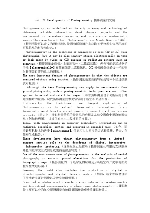
Channel Modeling for Terrestrial Free Space Optical LinksS. Sheikh Muhammad, P. Köhldorfer, E. LeitgebInstitute of Broadband Communications, TU Graz, Infeldgasse 12, 8010 Graz, Austria ABSTRACTWith recent advances and interest in Free Space Optics (FSO) for commercial deployments, a proper understanding of optical signal propagation in different atmospheric conditions has become essential, and thus arises the need to rationalize the effects of atmospheric channel on terrestrial FSO links. In this paper, we present the preliminary results of our effort to simulate the atmospheric free space terrestrial optical channel with precise mathematical models of the most deterrent attenuators. Attenuations due to fog, rain, snow and scintillation are considered. Thus, the channel model acquired is a first step towards developing a comprehensive model predicting the performance of a terrestrial FSO link operating under natural weather conditions.Keywords: Free Space Optics (FSO), atmospheric attenuations, channel modeling, optical propagation, scintillation losses.1. INTRODUCTIONThe concept of transmitting information through the air by means of a modulated light signal is quite old, and although significant advances have been made over the past 10 years, the concept remains relatively simple: a narrow beam of light is launched at a transmission station, transmitted through the atmosphere, and subsequently received at the receiving station [1]. The advances in the technology, now referred too as FSO, have come about in response to a need for greater bandwidth and improved communication systems. Free space optical communications has attracted a considerable attention for a variety of applications in the field of telecommunications. FSO applications span over a wide range from satellite links to robotics and generates interest for several distinct markets, namely: the last mile high bandwidth internet connectivity, the temporary high bandwidth data links, the mobile telephony backhaul (3G), satellite links as well as the various applications where the optical fibres cannot be used. In spite of the possibility of different applications, the terrestrial FSO links still remains of primary significance and the performance of such links is highly dependent on different weather conditions particularly in presence of fog. Severity and duration of the atmospheric effects affect the distance and the availability of the links. Thus, the interest aimed at this technology has developed the need to understand the effects of various weather conditions on the optical radiation propagation in the atmosphere. In general, weather and installation characteristics that impair or reduce visibility also effect the FSO performance. The effort here is to focus on some of the more important atmospheric attenuators and to simulate their attenuation behavior using precise mathematical relations, derived and improved over the years. A conscious effort has been made to select the best known and most suitable relations in modeling the FSO channel. Previously, a significant effort in this regard has been made by M. Achour [2, 3]; but much more is desired as to the best of our knowledge comprehensive channel models for terrestrial FSO communications still have many unanswered questions.2. CHANNEL MODELINGModeling the channel for terrestrial FSO is a problem of considerable complexity due to the variety of impairments possible and the disagreement over the mathematical modeling of the various phenomena. FSO links are impaired by absorption and scattering of light by earth’s atmosphere. The atmosphere interacts with the light due to the composition of the atmosphere, which normally consists of a variety of different molecular species and small suspended particles called aerosols. This interaction produces a variety of phenomena: frequency selective attenuation, absorption, scattering and scintillation. In addition, sunlight can affect FSO performance when the sun is colinear with the free space optical link. Frequency selective absorption at specific optical wavelengths comes from the interaction between the photons and atoms or molecules that leads to the extinction of the incident photon, elevation of the temperature, and radiative emission. Atmospheric scattering results from the interaction between the photons and the atoms and molecules in the propagation medium. Scattering causes angular redistribution of the radiation with or without modification of the wavelength. Scintillation is caused by thermal turbulence within the propagation medium that results in randomly distributed cells. These cells have variable sizes (10 cm – 1 km), temperatures, and refractive indices causing scattering, multipath and variation of the angles of arrival. As a result, the received signal amplitude fluctuates at frequencies ranging between 0.01 and 200 Hz. In addition, scintillation can cause wave front distortion resulting in defocusing of the beam.0-7803-9236-1/05/$20.00 ©2005 IEEE3. SIMULATING FSO SYSTEMSThe following input parameters of the simulation model are used: the transmitter is described by the transmitted power P trans [mW], the diameter of the active area is d transmitter [mm], the opening angle of the beam FOV (field of view) is θ [mrad], the transmitted wavelength is λ [nm] and the optical losses at the output of the transmitter are P opt [dB]. At the receiver the diameter of the receiving surface is of main interest and is described by d receiver[mm]. The geometrical losses P geo [dB] are calculated as in equation (1). Fig. 1 shows the available input power for the receiver. Further the channel-length l [m] can be chosen in the simulation tool. The weather influences for the channel are simulated for the used wavelength. For the fog simulation, the Kim and Kruse model are used. Additionally, rain or snowfalls are catered in the simulation. The snow behaves differently if it’s dry or wet, both scenarios are considered. A supplemented tool (Slider) deals with atmospheric turbulences (they can differ between low and high). The visibility value can be used from the reference or it can be varied.(1)Fig. 1.4. ATTENUATION MODELINGThe terrestrial FSO links must deal with the atmosphere just above the surface of the earth, where it has maximum density due to the gravitational force. Mie scattering due to aerosol and fog droplet distribution; which is by far the most complex to simulate; is considered the major atmospheric element that attenuates the optical signal.4.1 Fog AttenuationThe theoretical background of fog attenuation for light based on Mie Scattering can be found in [4-6] and is not being dealt with here. Several models exist which allow to calculate specific attenuation for different optical wavelengths based on visibility data. The two most widely used models that we used and implemented in our simulation are the Kruse model and the Kim model. The specific attenuation is calculated in equation (2), with the variables visibility V [km], wavelength λ [nm], visibility reference at wavelength λ0 [nm] and for transmission of air drops to V % percent of the clear sky; and the results are shown in figure 2. The wavelength dependency in this expression is expressed by q , which is in the Kruse model given by equation (3) and in the Kim model by equation (4). At very high attenuations the Kim model is the better model.(2)(3)(4) Fig. 2.4.2 Rain AttenuationRain is also an important attenuator for the optical signals and the specific attenuation for rain has been modelled as in equation (5) [7] where the rain rate is given by R [mm/h] and the dependence is drawn in figure 3. [][]km dB km V V a q spec −⎟⎟⎠⎞⎜⎜⎝⎛=0%log 10λλ⎪⎩⎪⎨⎧<<<>=km V if V km V km if km V if q 6585.05063.1506.131⎪⎪⎪⎩⎪⎪⎪⎨⎧<<<−<<+<<>=km V if km V km if V km V km if V km V km if km V if q 5.0015.05.06134.016.05063.1506.1[]dB l d d P r transmitte receiver geo 2log 10⎟⎟⎠⎞⎜⎜⎝⎛⋅+⋅=θ(5)Fig. 3.4.3 Snow AttenuationThe attenuation due to snow fall has been modelled based on dry or wet snows and the specific attenuation is given by equation (6) where S is the snow rate in [mm/h]. The Parameters a and b are given for dry snow in equation (7) and for wet snow in equation (8) where λ represent the transmission wavelength in [nm]. Figure 4 depicts the difference between wet and dry snowfall.(6)(7)(8) Fig. 4.5. SCINTILLATION LOSSESRandomly distributed cells are formed under the influence of thermal turbulence inside the propagation medium; the wave fronts vary causing the focussing and defocusing of the beam. Such fluctuations of the signal are called scintillations. The amplitude and frequency of scintillations depend on the size of the cells compared to the beam diameter [8]. The intensity and the speed of the fluctuations (scintillations frequency) increase with wave frequency. For a plane wave, a low turbulence and a specific receiver, the scintillation variance can be expressed as in equation (9) where λ represent the transmitter wavelength in [nm], l the channel-length in [m] and Cn 2 the refractive index structure parameter in [m -2/3]. Cn 2 is for low turbulence 10-16, for moderate turbulence 10-14 and for high turbulence 10-13 [9]. The dependence from Cn 2 is depicted in figure 5. For strong turbulences, a saturation of the variance given by above relationship is observed. The parameter Cn 2 does not have the same value at millimetre waves and at optical waves. Millimetre waves are especially sensitive to humidity fluctuations while in optic, refractive index is a primary function of the temperature.(9)Fig. 5.6. GRAPHICAL USER INTERFACEFigure 6 shows the Graphical User Interface (GUI) of our channel model; in the last two plots in figure 6 the “Power” represents the available input power for the receiver. Much more sophistication is of course possible, and there are ideas to include background ambient light in the future, as well as to produce a probability of error[]km dB R a rain /076.13/2=[]km dB S a a b snow /⋅=72.07855466.310023.14=+⋅=−b a λ][dB 10217.2326/1126/79l C a n scin ⋅⋅⎟⎠⎞⎜⎝⎛⋅=λπ38.14958776.51042.55=+⋅=−b a λestimation. This model can provide the basic platform to carry on further investigations and to the ultimate goal of achieving a well-formulated channel model for FSO, comparable to the existing RF models.Fig. 6.7. CONCLUSIONSThe channel modeling effort that we have presented in this paper is the first real attempt towards availability and reliability prediction of terrestrial FSO links through simulation. Molecular absorption is a selective phenomenon which results in a spectral transmission of the atmosphere presenting transparent zones, called atmospheric transmission window, and opaque zones, called atmospheric blocking windows, which have not be considered in this model. The model provides the basic tool to do further detailed investigations in terrestrial FSO applications, and can be improved and utilised for a variety of applications. We are also trying to validate the model by practical attenuation measurements that we perform on our installed FSO systems in Graz.REFERENCES[1] J. Schuster, H. Willebrand, S. Bloom, E. Korevaar: Understanding the performance of Free Space Optics,in Journal of Optical Networking, 2003.[2] M. Achour: Simulating atmospheric free space optical propagation; Part I, Rainfall attenuation, in SPIEproceedings, Vol. 3635, 2002.[3] M. Achour: Simulating atmospheric free space optical propagation; Part II, Haze, fog and low cloudsattenuations, in SPIE proceedings, vol. 4873, 2002.[4] F. de Fornel, M. Al Naboulsi, H. Sizun: Fog attenuation prediction for optical and infrared waves,in Journal SPIE, 2003.[5] F. de Fornel, M. Gebhart, E. Leitgeb, M. Al Naboulsi, H. Sizun: Availability prediction for free space opticcommunication systems from local climate visibility data, in Short Term Scientific Report 4. COST 270, 2003.[6] E. Korevaar, I.I. Kim, B. McArthur: Comparison of laser beam propagation at 785 nm and 1550 nm in fogand haze for optical wireless communications, in SPIE proceedings, vol. 4124, 2001.[7] T.H. Carbonneau, D.R. Wisley: Opportunities and Challenges for optical wireless; the competitiveadvantage of free space telecommunications links in today’s crowded market place, in SPIE Conference on Optical Wireless Communications, Massachusetts, 1998.[8] R.L. Philips, L.C. Andrews: Laser Beam Propagation through Random Media, in SPIE publications,Washington, 1998.[9] P.S.Ray: Broadband complex Refractive Indices of Ice and Water, in Applied Optics, vol. 11, 1972.。