Z1K600-RL-10中文资料
金龙机电有限公司产品说明书
中国金龙机电有限公司JINLONGMACHINERY&ELECTRONICSCO.,LTD.产品规格书PRODUCT SPECIFICATION地址:中国浙江省温州乐清北白象进港大道金龙科技园Add:Jinlong Science and Technology Park,Jingang Road,Beibaixiang,Yueqing,Wenzhou Zhejiang,China电话/Tel:86-577-6180167861806666传真/Fax:86-577-61801858Http://www.kotl.com.cn客户名称/Customer客户料号/PartNo.客户客户承认签章CustomerApprovedSignatures文件编号/Spec No.KOTL-601品名Description扁平振动马达CoinVibrationMotor型号/ModelC1026B002F送样日期/Date设计/Designed审核/checked批准/Approved敝司林梅琴2006.1.3熊明勇2006.1.3夏章辉2006.1.3规格书内容Contentsofspecifications1.适用范围/General本说明书适用于扁平式永磁直流电机C1026B系列.Thisspecificationappliestocoinpermanent-magneticmotorsDCmodelC1026Bseries2.使用条件/Operatingcondition3.测定条件/Measuringcondition4.初期电气性能/Electricalinitialcharacteristics项目/Item规格/Specification2-1额定电压Ratedvoltage3.0VDC2-2使用电压范围Operatingvoltage2.5~4.0VDC2-3旋转方向RotationCW(clockwise)orCCW(contraryclockwise)2-4使用环境Operatingenvironment-20~+60℃,OrdinaryHumidity2-5保存环境Storageenvironment-30~+70℃,OrdinaryHumidity项目/Item规格/Specification3-1温度Temperature25±3℃3-2湿度Humidity 65±20%RH3-3气压Airpressure1013±40hPa3-4电流Current稳压直流电流Stabilized DC current项目/Item规格/Specification条件/Condition4-1额定转速Ratedspeed9000rpmmin4-2额定电流Ratedcurrent90mAMax4-3起动电流Startingcurrent120mAMax额定电压下Atratedvoltage4-4起动电压Startingvoltage2.3VDCMax在最小起动电压下起动Motorisrotatingatminstartingvoltage.4-5绝缘电阻Insulationresistance10MΩMin在100V直流下,导线和机壳间AtDC100Vbetweenleadwireandcase.4-6端子阻抗Terminalresistance31Ω±15%(单相sigleposture)59Ω±15%(双相doubleposture)在25℃下At25℃项目/Item规格/Specification判定标准/Judgment6-2低温放置Low tempexposure温度/Temperature:–30℃时间/Time:96h6-3高温放置High temp.Exposure温度/Temperature:+70℃时间/Time:96h6-4湿度放置Humidityexposure温度/Temperature:+40℃湿度/Humidity:95%RH放置时间/Exposuretime:96h无水气凝结/Nocondensationofmoisture在常温常湿下放置4h后,马达应符合项7-2的要求。
ITV使用说明书-中文版
ITV1000-※1ITV2000-※1ITV3000-※1(模拟输出/电压型)使用说明书值此,谨对您选购SMC公司的产品表示诚挚的谢意。
请仔细阅读本使用说明书,相信必将有助于您正确使用本产品。
为以防万一,请您一定好好保管此说明书。
安全注意事项这里所描述到的,是提请您正确安全的使用本产品,以防止对您自身和他人造成危害和损害的各种注意事项。
请结合ISO 4414, JIS B 8370以及其他的相关安全规则,务必遵守。
!注意关于配管1.请将配管用空气吹净或清洗干净,以除去配管内的切屑,切削油及杂质等。
2.将配管和管接头拧紧时,请注意勿将配管的螺纹切屑及密封材混入配管中。
另需强调,使用密封胶带包卷管接头螺纹时,请在螺纹先端留出1.5~2个螺距的空间。
!注意关于压缩气源1. 在靠近本产品的供气侧,请选择安装过滤精度在5μm以下的空气过滤器。
2. 压缩空气若含有大量的水分,将导致本产品及其他的气动元件作动不良。
请实施相应对策,诸如设置后冷却器,空气干燥器,水分分离器等。
3. 由空气压缩机所产生的碳粉在本产品内部大量附着时,将导致其作动不良。
各部分名称外形尺寸安装孔配线电缆接线端子UP键(△键)设定键(SET键)DOWN键(▽键)安装托架(选配)右弯出线型电缆接线端子显示用LED(4芯)SUP接口压力表用接口OUT接口外形尺寸安装孔安装孔安装托架安装托架(选配)(选配)直线出线型电缆接线端子(4芯)右弯出线型电缆接线端子(4芯)安装孔■ 规格供给压力 注1) 设定压力+ 0.1MPa,但最大为1MPa0.005~0.1MPa (ITV101※-※1,ITV201※-※1,ITV301※-※1)0.005~0.5MPa (ITV103※-※1,ITV203※-※1,ITV303※-※1)设定压力0.005~0.9MPa (ITV105※-※1,ITV205※-※1,ITV305※-※1)约200L/min (ANR) {ITV1000}(供给压力:0.7MPa)约1500L/min (ANR) {ITV2000}(供给压力:0.7MPa)最大流量约5000L/min (ANR) {ITV3000}(供给压力:0.7MPa)24VDC±10% (ITV10※0-※1,ITV20※0-※1,ITV30※0-※1)电源电压 注2)12~15VDC (ITV10※1-※1,ITV20※1-※1,ITV30※1-※1)电源电压 DC24V型:0.12A以下消费电流电源电压 DC12~15V型:0.18A以下4~20mADC (ITV10※※-01,ITV20※※-01,ITV30※※-01)电流型0~20mADC (ITV10※※-11,ITV20※※-11,ITV30※※-11)0~5VDC (ITV10※※-21,ITV20※※-21,ITV30※※-21)输入信号 注2)电压型0~10VDC (ITV10※※-31,ITV20※※-31,ITV30※※-31)电流型 250Ω以下输入阻抗电压型 约6.5KΩ直线性 ±1.0% F.S.以下延滞性 0.5% F.S.以下重复精度 ±0.5% F.S.以下最小压力调整 :调整范围 额定值的0~50%最大压力调整 :调整范围 额定值的10~100%附加机能键锁定机能 :持续摁住UP键2秒以上,再摁住SET键,可实现对操作键的锁定。
单向离合器型号

【MZ系列单向轴承】单向超越离合器MZ15 单向超越离合器MZ17 单向超越离合器MZ20单向超越离合器MZ30-22 单向超越离合器MZ30-35 单向超越离合器MZ30单向超越离合器MZ35 单向超越离合器MZ45-40 单向超越离合器MZ45—40单向超越离合器MZ60-50 单向超越离合器MZ60 单向超越离合器MZ70—65单向超越离合器MZ70【MZ-G单向轴承】单向超越离合器MZ15G 单向超越离合器MZ17G 单向超越离合器MZ20G单向超越离合器MZ30G—22 单向超越离合器MZ30G-25 单向超越离合器MZ30G 单向超越离合器MZ35G 单向超越离合器MZ45G—40 单向超越离合器MZ45G单向超越离合器MZ60G—50 单向超越离合器MZ60G-55 单向超越离合器MZ60G 单向超越离合器MZ70G-65 单向超越离合器MZ70G【200系列凸轮离合器】凸轮离合器B203 凸轮离合器B204 凸轮离合器B205 凸轮离合器B206凸轮离合器B207 凸轮离合器B208 凸轮离合器B209 凸轮离合器B210凸轮离合器B211 凸轮离合器B212 凸轮离合器B213 凸轮离合器B214【单向离合器】单向轴承CSK12P 单向轴承CSK15P 单向轴承CSK17P 单向轴承CSK20P单向轴承CSK25P 单向轴承CSK30P 单向轴承CSK35P 单向轴承CSK40P单向轴承CSK15PP 单向轴承CSK17PP 单向轴承CSK20PP 单向轴承单向轴承CSK30PP 单向轴承CSK35PP 单向轴承CSK40PP单向轴承CSK12P-2RS 单向轴承CSK15P-2RS 单向轴承CSK17P-2RS单向轴承CSK20P—2RS 单向轴承CSK25P-2RS 单向轴承CSK30P-2RS单向轴承CSK35P-2RS 单向轴承CSK40P-2RS【BB系列凸轮离合器】凸轮离合器BB15 凸轮离合器BB17 凸轮离合器BB20 凸轮离合器BB25凸轮离合器BB30 凸轮离合器BB35 凸轮离合器BB40凸轮离合器BB15—1K—K 凸轮离合器BB15-2K—K 凸轮离合器BB17-1K-K凸轮离合器BB17—2K-K 凸轮离合器BB20—1K-K 凸轮离合器BB20—2K—K凸轮离合器BB25—1K-K 凸轮离合器BB25-2K—K 凸轮离合器BB30-1K—K凸轮离合器BB30-2K-K 凸轮离合器BB35—1K-K 凸轮离合器BB35-2K—K凸轮离合器BB40-1K-K 凸轮离合器BB40—2K-K凸轮离合器BB15—2GD 凸轮离合器BB17-2GD 凸轮离合器BB20—2GD凸轮离合器BB25-2GD BB30-2GD 凸轮离合器BB35-2GD 凸轮离合器BB40-2GD【GFK单向离合器轴承】单向离合器GFK20 单向离合器GFK25 单向离合器GFK30 单向离合器GFK35单向离合器GFK40 单向离合器GFK45 单向离合器GFK50【BWC。
艾森·摩尔尔系列ZB超压保护设备说明书

Eaton 278467Eaton Moeller® series ZB Overload relay, ZB150, Ir= 25 - 35 A, 1 N/O, 1 N/C, Separate mounting, IP00Algemene specificatiesEaton Moeller® series ZB Thermal overload relay278467134 mm121 mm 118 mm 1.394 kgUL 60947-4-1 CSA File No.: 012528 CSA-C22.2 No. 60947-4-1-14 IEC/EN 60947 UL File No.: E29184 CECSA Class No.: 3211-03 VDE 0660 IEC/EN 60947-4-1 ULUL Category Control No.: NKCR CSAZB150-35/KKProduct NameCatalog Number Product Length/Depth Product Height Product Width Product Weight Certifications Model CodeReset pushbutton manual/autoPhase-failure sensitivity (according to IEC/EN 60947, VDE 0660 Part 102) Test/off button Trip-free release-25 °C55 °C-25 °C40 °C CLASS 10 A Damp heat, constant, to IEC 60068-2-78 Damp heat, cyclic, to IEC 60068-2-30IP00ZB150Separate mounting Direct attachment25 A35 AIII3Finger and back-of-hand proof, Protection against direct contact when actuated from front (EN 50274)FeaturesAmbient operating temperature - min Ambient operating temperature - max Ambient operating temperature (enclosed) - min Ambient operating temperature (enclosed) - max Class Climatic proofingDegree of protection Frame size Mounting method Overload release current setting - min Overload release current setting - max Overvoltage category Pollution degree Product category ProtectionAccessoriesOverload relay ZB up to 150 A6000 V AC4000 V (auxiliary and control circuits)10 g, Mechanical, Sinusoidal, Shock duration 10 ms Branch circuits, (UL/CSA)Continuous≤ 0.25 %/K, residual error for T > 40°1 x (0.75 - 2.5) mm², Control circuit cables1 x (4 - 70) mm², Main cables2 x (4 - 70) mm², Main cables2 x (0.75 - 2.5) mm², Control circuit cables1 x (4 - 16) mm², Main cables2 x (4 - 16) mm², Main cables2 x (0.75 - 4) mm², Control circuit cables1 x (0.75 - 4) mm², Control circuit cables3/0, Main cables2 x (18 - 14), Control circuit cables1 x (16 - 70) mm², Main cables2 x (16 - 70) mm², Main cables24 mm8 mmM10, Terminal screw, Main cables5 mm AF, Hexagon socket-head spanner, Terminal screw, Main cablesM3.5, Terminal screw, Control circuit cables1 x 6 mm, Terminal screw, Control circuit cables, Standard screwdriver2, Terminal screw, Control circuit cables, Pozidriv screwdriver1.2 Nm, Screw terminals, Control circuit cables10 Nm, Screw terminals, Main cables6 A 5 kA, SCCR (UL/CSA)60 A Class J, max. Fuse, SCCR (UL/CSA)Rated impulse withstand voltage (Uimp)Shock resistanceSuitable forTemperature compensation Terminal capacity (flexible with ferrule)Terminal capacity (solid)Terminal capacity (solid/stranded AWG) Terminal capacity (stranded)Stripping length (main cable)Stripping length (control circuit cable) Screw sizeScrewdriver sizeTightening torqueConventional thermal current ith of auxiliary contacts (1-pole, open)Rated operational current (Ie) at AC-15, 120 V Short-circuit current rating (basic rating) Short-circuit protection rating1.5 A1.5 A0.9 A0.4 A0.2 A0.9 A0.75 A1000 V440 V, Between auxiliary contacts and main contacts, According to EN 61140240 V AC, Between auxiliary contacts, According to EN 61140 440 V AC, Between main circuits, According to EN 61140B600 at opposite polarity, AC operated (UL/CSA)R300, DC operated (UL/CSA)B300 at opposite polarity, AC operated (UL/CSA)600 VAC600 VAC 100 A gG/gL, Fuse, Type “2” coordination125 A gG/gL, Fuse, Type “1” coordinationMax. 6 A gG/gL, fuse, Without welding, Auxiliary and control circuits111121 W0 W7 W35 A0 WMeets the product standard's requirements.Meets the product standard's requirements.Meets the product standard's requirements.Meets the product standard's requirements.Rated operational current (Ie) at AC-15, 220 V, 230 V, 240 V Rated operational current (Ie) at AC-15, 380 V, 400 V, 415 V Rated operational current (Ie) at DC-13, 110 VRated operational current (Ie) at DC-13, 220 V, 230 V Rated operational current (Ie) at DC-13, 24 VRated operational current (Ie) at DC-13, 60 VRated operational voltage (Ue) - maxSafe isolationSwitching capacity (auxiliary contacts, pilot duty) Voltage rating - maxVoltage rating - max Number of auxiliary contacts (change-over contacts)Number of auxiliary contacts (normally closed contacts) Number of auxiliary contacts (normally open contacts) Number of contacts (normally closed contacts)Number of contacts (normally open contacts)Equipment heat dissipation, current-dependent PvidHeat dissipation capacity PdissHeat dissipation per pole, current-dependent PvidRated operational current for specified heat dissipation (In) Static heat dissipation, non-current-dependent Pvs10.2.2 Corrosion resistance10.2.3.1 Verification of thermal stability of enclosures10.2.3.2 Verification of resistance of insulating materials to normal heat10.2.3.3 Resist. of insul. mat. to abnormal heat/fire by internal elect. effectsMeets the product standard's requirements.Does not apply, since the entire switchgear needs to be evaluated.Does not apply, since the entire switchgear needs to be evaluated.Meets the product standard's requirements.Does not apply, since the entire switchgear needs to be evaluated.Meets the product standard's requirements.Does not apply, since the entire switchgear needs to be evaluated.Does not apply, since the entire switchgear needs to be evaluated.Is the panel builder's responsibility.Is the panel builder's responsibility.Is the panel builder's responsibility.Is the panel builder's responsibility.Is the panel builder's responsibility.The panel builder is responsible for the temperature rise calculation. Eaton will provide heat dissipation data for the devices.Is the panel builder's responsibility. The specifications for the switchgear must be observed.eaton-tripping-zb-overload-relay-characteristic-curve.epsDA-DC-00004845.pdfDA-DC-00004855.pdfDA-CE-ETN.ZB150-35_KKIL03407006ZDA-CD-zb150_kkDA-CS-zb150_kkeaton-tripping-devices-overload-relay-zb-overload-relay-dimensions-007.epseaton-tripping-devices-overload-relay-zb-overload-relay-3d-drawing-005.eps10.2.4 Resistance to ultra-violet (UV) radiation10.2.5 Lifting10.2.6 Mechanical impact10.2.7 Inscriptions10.3 Degree of protection of assemblies10.4 Clearances and creepage distances10.5 Protection against electric shock10.6 Incorporation of switching devices and components 10.7 Internal electrical circuits and connections10.8 Connections for external conductors10.9.2 Power-frequency electric strength10.9.3 Impulse withstand voltage10.9.4 Testing of enclosures made of insulating material 10.10 Temperature rise10.11 Short-circuit rating10.12 Electromagnetic compatibility Characteristic curve Declarations of conformity eCAD model Installatiehandleidingen mCAD model TekeningenEaton Corporation plc Eaton House30 Pembroke Road Dublin 4, Ireland © 2023 Eaton. Alle rechten voorbehouden. Eaton is a registered trademark.All other trademarks areproperty of their respectiveowners./socialmediaIs the panel builder's responsibility. The specifications for the switchgear must be observed.The device meets the requirements, provided the information in the instruction leaflet (IL) is observed.10.13 Mechanical function。
二极管代用资料

15
AU01Z
2CZ5295G、S5295G、ZRU3、Z1883、ZEM01Z、ZEU1C、Z1834、ZRG2
可用于190V视放电压整流,场泵电源升压
16
ZRU4Z
HER305 、ZRU4AM、HER303 、BYM26D、BY359、 BY328
通常用于低压大电流整流电路,如伴音功放供电等。
25″及以上屏幕尺寸彩电开关电源+300V 电压整流二极管
适应所有大屏幕彩电开关电源
11
IN5408
BY254、Z5A6
25″及以上屏幕尺寸彩电开关电源+300V 电压整流二极管
适应所有大屏幕彩电开关电源
12
Z5A6
IN5408、BY254
25″及以上屏幕尺寸彩电开关电源+300V 电压整流二极管
适应所有大屏幕彩电开关电源
1N4148、2CK75、BAV21之间可以互换。
20
21
17
ZRU2
2CZ5295G、S5295G、ZRU3、Z1883、ZEM01Z、ZEU1C、Z1834、ZRG2
可用于190V视放电压整流,场泵电源升压,及其它低压小电流整流电路。
ZRU2不能代换ZRU3
18
ERC2006
BY359
大屏幕彩电枕校调制二极管
19
1N4148
2CK75、BAV21
普通二极管
13AK03AK04、K源自33/K346/K344/K342
高速开关二极管参数:正向压降VFM0.55V,正相工作电流:IF1A,反向电压VR30V,反向流电流1K(UA)。
该二极管正向阻值约200Ω左右,反向阻值近∞,主要用于STR-G6454/6656系列开关电源。
KTR10资料

Resistors Rev.A 1/6Endured high voltage fixed thick film chip resistorKTR10 (0805 size : 1 / 8W )z Features1) Power rating of 1 / 8W2) Limiting element voltage of KTR series is twice compared with that of MCR series. 3) Highly reliable chip resistorRuthenium oxide dielectric offers superior resistance to the elements. 4) ROHM resistors have approved ISO–9001 certification.Design and specifications are subject to change without notice. Carefully check the specification sheet before using or ordering it.z Ratings0.125W (1 / 8W)−55°C to + 155°Cat 70°CItemConditionsSpecificationsRated powerRated voltageOperating temperatureNominal resistance See Table 1.Limiting element voltage 300V20406080100−55070100155AMBIENT TEMPERATURE (°C)P O W E R L O A D (%)Fig.1The voltage rating is calculated by the following equation. If the value obtained exceeds the limiting element voltage, the voltage rating is equal to the maximum operating voltage.E: Rated voltage (V)P: Rated power (W)R: Nominal resistance (Ω)E= P ×RPower must be derated according to the power derating curve in Figure 1 when ambient temperature exceeds 70°C .Resistors Rev.A 2/6F (±1%)J (±5%)1 ≤ R ≤ 10M (E24,96)(E24)±100±2001 ≤ R ≤ 10M Table 1Resistance toleranceResistance range(Ω)Resistance temperature coefficient(ppm/°C)z Before using components in circuits where they will be exposed to transients such as pulse loads (short–duration, high– level loads), be certain to evaluate the component in the mounted state. In addition, the reliability and performance of this component cannot be guaranteed if it is used with a steady state voltage that is greater than its rated voltage.z CharacteristicsItemTest conditions (JIS C 5201-1)Resistor typeGuaranteed value ResistanceVariation of resistance with temperature SolderabilityDamp heat, steady stateEndurance at 70°CEnduranceRapid change of temperatureBend strength of the end face platingResistance to solventResistance to soldering heat Overload± (2.0%+0.1Ω)± (3.0%+0.1Ω)J : ±5%F : ±1%± (1.0%+0.05Ω)No remarkable abnormality on the appearance.A new uniform coating of minimum of 95% of the surface being immersed and no soldering damage.JIS C 5201-1 4.5JIS C 5201-1 4.8Measurement : −55 / +25 / +125°C JIS C 5201-1 4.18Soldering condition : 260±5°C Duration of immersion : 10±1s.JIS C 5201-1 4.2440°C, 93%RHTest time : 1,000h to 1,048h ± (3.0%+0.1Ω)± (3.0%+0.1Ω)± (1.0%+0.05Ω)± (1.0%+0.05Ω)Without mechanical damage such as breaks.± (1.0%+0.05Ω)JIS C 5201-1 4.25.1Rated voltage (current), 70°C 1.5h : ON − 0.5h : OFFTest time : 1,000h to 1,048h JIS C 5201-1 4.25.3155°CTest time : 1,000h to 1,048hJIS C 5201-1 4.2923±5°C, Immersion cleaning, 5±0.5min.Solvent : 2-propanol JIS C 5201-1 4.19Test temp. : −55°C to +125°C 5cyc JIS C 5201-1 4.33JIS C 5201-1 4.17Rosin·Ethanol (25%WT)Soldering condition : 235±5°C Duration of immersion : 2.0±0.5s.JIS C 5201-1 4.13Rated voltage (current) ×2.5, 2s.Maximum overload voltage : 600V See Table.1Resistors Rev.A 3/6z External dimensions (Unit : mm)z PackagingResistors Rev.A 4/6z Part designationPart No.K T 01R Resistance toleranceF JNominal resistanceE Z P J±1%±5%Reel (φ180) : JEITA ET-7200B: Standard productF J::3 digits4 digitsResistance code, 3 or 4 digits.Resistance toleranceResistance codezDimensionsRESISTANCE (Ω)Fig.2 Dimensions (length)L E N G T H (m m )RESISTANCE (Ω)Fig.3 Dimensions (width)W I D T H (m m )RESISTANCE (Ω)Fig.4 Dimensions (thickness)T H I C K N E S S (m m )z Electrical characteristics−−−RESISTANCE (Ω)Fig.5 Resistance (J class)D C R E S I S T A N C E (%)−−−RESISTANCE (Ω)Fig.6 Resistance (F class)D C RE S I S T A N C E (%)−−−−−RESISTANCE (Ω)Fig.7 Variation resistance with temperature (J class)T E M P E R A T U R E C O E F F I C I E N T (p p m /°C )Resistors Rev.A 5/6+−−−−−RESISTANCE (Ω)Fig.8 Variation resistance with temperature (F class)T E M P E R A T U R E C O E F F I C I E N T (p p m /°C )RESISTANCE (Ω)Fig.9 Overload ∆R /R (%)−−−−−RESISTANCE (Ω)Fig.10 SolderabilityS O L D E R D P E R C E N T A G E (%)RESISTANCE (Ω)Fig.11 Resistance to soldering heat∆R /R (%)−−−−−RESISTANCE (Ω)Fig.12 Rapid change of temperature∆R /R (%)−−−−−−−−−RESISTANCE (Ω)Fig.13 Damp heat, steady state∆R /R (%)−−−−RESISTANCE (Ω)Fig.14 Endurance at 70°C ∆R /R (%)−−−−RESISTANCE (Ω)Fig.15 Endurance ∆R /R (%)−−−−RESISTANCE (Ω)Fig.16 Component solvent resistance∆R /R (%)Resistors Rev.A 6/6RESISTANCE (Ω)Fig.17 Bend strength of the end face plating∆R /R (%)−−−−−AppendixAbout Export Control Order in JapanProducts described herein are the objects of controlled goods in Annex 1 (Item 16) of Export T rade ControlOrder in Japan.In case of export from Japan, please confirm if it applies to "objective" criteria or an "informed" (by MITI clause)on the basis of "catch all controls for Non-Proliferation of Weapons of Mass Destruction.Appendix1-Rev1.1。
Eaton Moeller PKZM01电机保护电路保护器说明说明书

Eaton 278475Eaton Moeller® series PKZM01 Motor-protective circuit-breaker, 660 V 690 V: 0.06 kW, Ir= 0.1 - 0.16 A, IP20 PKZM01-0,16General specificationsEaton Moeller® series PKZM01 Motor-protective circuit-breaker278475401508278475193 mm 90 mm 45 mm 0.253 kgIEC/EN 60947CSA-C22.2 No. 60947-4-1-14 UL Category Control No.: NLRV UL 60947-4-1CSA Class No.: 3211-05 VDE 0660 CECSA File No.: 165628 IEC/EN 60947-4-1 ULUL File No.: E36332 CSA UL CSAProduct NameCatalog Number EANProduct Length/Depth Product Height Product Width Product Weight Certifications0.16 A2 x (1 - 6) mm², ferrule to DIN 462281 x (1 - 6) mm², ferrule to DIN 46228Is the panel builder's responsibility. The specifications for the switchgear must be observed.25 °C0 kWMeets the product standard's requirements.Is the panel builder's responsibility. The specifications for the switchgear must be observed.Does not apply, since the entire switchgear needs to be evaluated.0.16 A (3 contacts in series), DC-5 up to 250V0.16 A, AC-3 up to 440 V10 mm40 °C50 kAMeets the product standard's requirements.40 °C2.5 A eaton-manual-motor-starters-characteristic-characteristic-curve-008.eps eaton-manual-motor-starters-characteristic-characteristic-curve.epsDA-DC-00004884.pdfDA-DC-00004914.pdfETN.PKZM01-0,16IL03407011ZIL122012ZUIL03402034ZIL122023ZUDA-CS-pkzm01DA-CD-pkzm01Rated operational current for specified heat dissipation (In) Terminal capacity (flexible with ferrule)10.11 Short-circuit ratingAmbient operating temperature (enclosed) - minRated operational power at AC-3, 380/400 V, 50 Hz10.4 Clearances and creepage distances10.12 Electromagnetic compatibility10.2.5 LiftingSwitching capacityStripping length (main cable)Ambient operating temperature (enclosed) - maxRated short-circuit breaking capacity Icu at 400 V AC 10.2.3.1 Verification of thermal stability of enclosures Ambient storage temperature - minAdjustment range undelayed short-circuit release - max 10.8 Connections for external conductors Characteristic curve Declarations of conformity eCAD model Instrucciones de instalación Manuales y guías de uso mCAD modelIs the panel builder's responsibility.ProtectionFinger and back-of-hand proof, Protection against direct contact when actuated from front (EN 50274)Actuator typePush buttonAmbient operating temperature - max55 °CRated operational power at AC-3, 220/230 V, 50 Hz0 kWClimatic proofingDamp heat, cyclic, to IEC 60068-2-30Damp heat, constant, to IEC 60068-2-78Device constructionBuilt-in device fixed built-in techniqueFeaturesPhase-failure sensitivity (according to IEC/EN 60947-4-1, VDE 0660 Part 102)Lifespan, electrical50,000 operations (at 400V, AC-3)Static heat dissipation, non-current-dependent Pvs0 WElectrical connection type of main circuitScrew connection10.9.3 Impulse withstand voltageIs the panel builder's responsibility.Number of polesThree-poleAmbient operating temperature - min-25 °C10.6 Incorporation of switching devices and componentsDoes not apply, since the entire switchgear needs to be evaluated.10.5 Protection against electric shockDoes not apply, since the entire switchgear needs to be evaluated.Mounting positionCan be snapped on to IEC/EN 60715 top-hat rail with 7.5 or15 mm height.Rated uninterrupted current (Iu)0.16 ATripping characteristicOverload trigger: tripping class 10 AShort-circuit release2.5 A, Irm, Setting range max.± 20% tolerance, Trip blocksBasic device fixed 15.5 x Iu, Trip Blocks10.13 Mechanical functionThe device meets the requirements, provided the information in the instruction leaflet (IL) is observed.10.2.6 Mechanical impactDoes not apply, since the entire switchgear needs to be evaluated.10.9.4 Testing of enclosures made of insulating materialIs the panel builder's responsibility.10.3 Degree of protection of assembliesDoes not apply, since the entire switchgear needs to be evaluated.Heat dissipation per pole, current-dependent Pvid1.8 WOperating frequency25 Operations/hProduct categoryMotor protective circuit breakerOverload release current setting - min0.1 AEquipment heat dissipation, current-dependent Pvid5.39 WHeat dissipation capacity Pdiss0 WRated operational current (Ie)0.16 ASuitable forBranch circuit: Manual type E if used with terminal, or suitable for group installations, (UL/CSA)Also motors with efficiency class IE3Internal resistance68000 mΩTemperature compensation-25 - 55 °C, Operating range-5 - 40 °C to IEC/EN 60947, VDE 0660≤ 0.25 %/K, residual error for T > 40°Terminal capacity (solid)2 x (1 - 6) mm²1 x (1 - 6) mm²Rated frequency - min50 HzShort-circuit current60 kA DC, up to 250 V DC, Main conducting pathsPower loss5.39 W10.2.3.2 Verification of resistance of insulating materials to normal heatMeets the product standard's requirements.10.2.3.3 Resist. of insul. mat. to abnormal heat/fire by internal elect. effectsMeets the product standard's requirements.Lifespan, mechanical50,000 Operations (Main conducting paths)Terminal capacity (solid/stranded AWG)18 - 10Overload release current setting - max0.16 A10.9.2 Power-frequency electric strengthIs the panel builder's responsibility.Overvoltage categoryIIIDegree of protectionTerminals: IP00IP20Rated frequency - max60 HzSwitch off techniqueThermomagneticAmbient storage temperature - max80 °CAdjustment range undelayed short-circuit release - min2.5 APollution degree310.7 Internal electrical circuits and connectionsIs the panel builder's responsibility.Rated impulse withstand voltage (Uimp)6000 V ACConnectionScrew terminals10.10 Temperature riseThe panel builder is responsible for the temperature rise calculation. Eaton will provide heat dissipation data for the devices.FunctionsPhase failure sensitiveMotor protectionTightening torque1.7 Nm, Screw terminals, Main cableRated operational voltage (Ue) - min690 V10.2.2 Corrosion resistanceMeets the product standard's requirements.10.2.4 Resistance to ultra-violet (UV) radiationMeets the product standard's requirements.10.2.7 InscriptionsMeets the product standard's requirements.Shock resistance25 g, Mechanical, according to IEC/EN 60068-2-27, Half-sinusoidal shock 10 msRated operational voltage (Ue) - max690 VAltitudeMax. 2000 mEaton Corporation plc Eaton House30 Pembroke Road Dublin 4, Ireland © 2023 Eaton. Todos los derechos reservados. Eaton is a registered trademark.All other trademarks areproperty of their respectiveowners./socialmedia。
Klixon单相电机保护器产品说明说明书
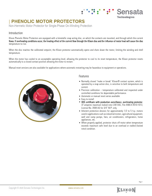
Features•Normally closed “make or break” Klixon® contact system, which is operated by a snap action disc, is sensitive to both temperature and current.•Precision calibration – temperature calibrated and inspected under controlled conditions for dependable performance.•Automatic or manual reset series available •Easy to install •37 amperes maximum locked rotor 230 VAC, File 4464.4-4510-1013, License No. 3938 UG for 3/4” M.P. only.•Inherent protection devices for approximately 1/2 to 5 h.p. motors used in applications such as industrial motors, agricultural equipment,well and sump pumps, fans, air conditioners, refrigerators, home appliances, etc.•When properly applied, protector shuts off motor when temperature exceeds maximum safe level due to an overload or stalled (locked rotor) condition.| PHENOLIC MOTOR PROTECTORSNon-Hermetic Motor Protector for Single-Phase On-Winding ProtectionIntroductionKlixon Phenolic Motor Protectors are equipped with a bimetallic snap acting disc, on which the contacts are mounted, and through which the current temperature to rise.When the disc reaches the calibrated setpoint, the Klixon protector automatically opens and shuts down the motor, limiting the winding and shell temperature.When the motor has cooled to an acceptable operating level, allowing the protector to cool to its reset temperature, the Klixon protector resets automatically to a closed contact position allowing the motor to restart.Manual reset versions are also available for applications where automatic restarting may be hazardous to equipment or operations.Automatic Reset Exploded ViewCover (Optional)Bimetal DiscHeater TerminalTerminalTerminalAdjusting ScrewPhenolic BaseContacts OpenContacts ClosedManual ResetSPECIFICATIONS DiagramsCurvesMetric Dimensions in ParenthesesDIMENSIONSRound BaseEared Base(Type ME 4-Holes. Type CE 2-Holes at #1Terminal End only. Other Types No Holes)ORDERING OPTIONSMaximum Recommended Protector Contact RatingsThis chart is used to determine protector size needed when making an application.Size Disc Contacts Terminals Max. CurrentV = 120Max. Current V = 2403/4”3/4”1”1”1”1”11/4”11/2”HCHCLCHCLCHCSTDSTDLCHCLCLCHCHCSTDSTD325040404080135175253730303060100130 HC = High Capacity LC = Low Capacity STD = Standard CapacityFor reference only. Please contact Sensata for application assistance.3/4”1”High Cap Low Cap High CapA B C D EJ L R ABADAEAFAGAHAIAJAKALAMAPFGJPLSOTABAEAFAGAHAIAJAKALAMANCDEHIKXAutomatic ResetOpen ±5°C Close ±9°CJKLVZNXYWUMRSH**P**O**= 90= 105= 105= 105= 120= 120= 120= 120= 135= 135= 135= 135= 135= 150**= 150**= 150**57**616978616978926169789210278**115**102**Manual ResetOpen ±5°C Close ±12°CGFABDE**= 90= 105= 105= 120= 135= 150**54**63***74*749696*** 1-Phase Protectors only.** Special temperatures.Consult net additions.*** 3-Phase Protectors only.Disc and Contact Operating TemperaturePage 7Sensata Technologies, Inc. (“Sensata”) data sheets are solely intended to assist designers (“Buyers”) who are developing systems that incorporate Sensata products (also referred to herein as “components”). Buyer understands and agrees that Buyer remains responsible for using its independent analysis, evaluation and judgment in designing Buyer’s systems and products. Sensata data sheets have been created using standard laboratory conditions and engineering practices. Sensata has not conducted any testing other than thatimprovements and other changes to its data sheets or components without notice.of sale supplied at CONTACT US AmericasEurope, Middle East & AfricaAPPLICATION WORKSHEETA sample worksheet provides the information needed for a proper application. It is not possible to apply a Klixon protector based on horsepower, amperage, or name plate data only.Motor DataA. Locked Rotor Requirements1. Locked Rotor Current Cold: the current which exists the instant the motor is turned on.2. Locked Rotor Current Hot: The current level that exists at end of 1st cycle3. Time elapsed during above test to raise motor winding temperature from room temperature to around maximum allowed temperature for the UL class of motor insulation. An example would be, for a class A motor, 25ºC to 175ºC in 12.5 seconds.4. Ambient Temperature During test: Room temperature (usually 25ºC).B. Running Overload Requirements1. Load Current: With the motor running, the load on the motor is to be increased in small increments until the motor winding has completely stabilized at approximately 10ºC below the maximum allowed by the UL class of the motor. An example would be, for a class A motor, the maximum allowed is 140øC. The motor winding temperature was completely stabilized at 130ºC and the current draw at that time would be recorded.2&3. Protector Location Temperatures: These temperatures are taken at the conclusion of the above load current test while the motor is running under the above load.4. Ambient Temperature: Room temperature (usually 25ºC).C. Abnormal Conditions for Protection.1. Max/min Ambient Temperatures: temperature in the surroundings of protector.2. Max/min Line Volts: The highest and lowest voltages for which protection should be effective.3. Other environmental considerations: i.e., exposed to agricultural weather Plate DataA. HorsepowerB. VoltageC. Single or three phaseD. FLA (full load amps)E. LRA (locked rotor amps)F. Insulation class (UL/CSA) (indicate one)Protector RequirementsA. Automatic or manual resetB. Round or eared baseC. Termination typeMotor Data RequiredA. Locked rotor requirements1. Locked rotor current cold2. Locked rotor current hot3. Time required to raise motor winding to max.temperature4. Ambient temperature during testB. Running overload requirements1. Load current required to stabilize mainwinding temp. at 10ºC below maximumallowed2. Protector location temperature belowprotector surface3. Protector location temperature aboveprotector (air temp)4. Ambient temp during testC. Abnormal conditions for protection1. Max/min ambient temperatures2. Max/min line volts3. Other environmental considerationsNote: Application assistance available from Sensata.H.PVoltsPhaseAmpsAmpsABFHAmpsAmpsSecDegAmpsDegDegDegDegVolts+1 508 236 2551electrical-protection-sales@+3 174 357 8156*********************.com**************************China +86 (21)2306 1651India +91 (40)4033 9611Japan +81 (45)277 7104Korea +82 (53) 644 9685Rest of Asia +65(6478)6860。
- 1、下载文档前请自行甄别文档内容的完整性,平台不提供额外的编辑、内容补充、找答案等附加服务。
- 2、"仅部分预览"的文档,不可在线预览部分如存在完整性等问题,可反馈申请退款(可完整预览的文档不适用该条件!)。
- 3、如文档侵犯您的权益,请联系客服反馈,我们会尽快为您处理(人工客服工作时间:9:00-18:30)。
The terminal electrode & the dielectric must not be damaged by the forces applied on the right conditions.
For Z Series : Size 1 2 3 4 5 6 Force (Kfg) 0.2 0.5 0.6 1.0 1.0 1.0 1.5 2.0 > 25 Time (sec)
元器件交易网
FERRITE CHIP BEADS
6. ELECTRICAL CHARACTERISTICS : Part Number Z1K100-RL-10 Z1K300-RL-10 Z1K600-RL-10 Z1K800-RL-10 Z1K900-RL-10 Z1K101-RL-10 Z1K121-RL-10 Z1K221-RK-10 Z1K301-RK-10 Impedance ( ) 10 ±25% 30 ±25% 60 ±25% 80 ±25% 90 ±25% 100 ±25% 120 ±25% 220 ±25% 300 ±25% Test Frequency ( MHz ) 100 100 100 100 100 100 100 100 100 DC Resistance ( ) Max. 0.10 0.10 0.10 0.10 0.10 0.10 0.10 0.15 0.15
03.07.2008
SUPERWORLD ELECTRONICS (S) PTE LTD
PG. 4
元器件交易网
FERRITE CHIP BEADS
8. RELIABILITY & TEST CONDITION :
Z1 SERIES
ITEM
Bending Strength
Preheat : 150°C, 60sec. Solder : Sn-Ag3.0-Cu0.5 Solder Temperature : 245±5°C Flux for lead free : rosin Dip Time : 4±1sec.
60 seconds
4±1.0 seconds
Terminal Strength
L 2.10 Ref.
1.00±0.10 0.50±0.10 0.50±0.10 0.25±0.10
3. SCHEMATIC :
4. MATERIALS : b a
Ag(100%) Ni(100%)-1.5um(min.) Sn(100%)-3.0um(min.)
(a) Body : Ferrite (b) Termination : Ag/Ni/Sn
(e) R : Reel (f) Current code : L = 2000mA (g) 10 : Lead Free
2. CONFIGURATION & DIMENSIONS :
A D L G H B C
PCB Pattern Unit:m/m
A
B
C
D
G 0.50 Ref.
H 0.55 Ref.
03.07.2008
SUPERWORLD ELECTRONICS (S) PTE LTD
PG. 3
元器件交易网
FERRITE CHIP BEADS
8. RELIABILITY &aITEM
Electrical Characteristics Test Impedance DC Resistance Rated Current Temperature Rise Test Solder Heat Resistance
Refer to standard electrical characteristics list
30°C max. ( t) Appearance : No significant abnormality Impedance change : Within ±30%
Preheating Dipping 260°C 150°C Natural cooling
160
Z1K800-RL-10 HCB1005KF-800T20
IMPEDANCE(Ohm)
IMPEDANCE(Ohm)
120
120
80
Z
Z
80
40
X
40
X
0 1 10
R
100 1000
R
0 1 10 100 1000
FREQUENCY(MHz)
FREQUENCY(MHz)
NOTE : Specifications subject to change without notice. Please check our website for latest information.
80
Z1K300-RL-10 HCB1005KF-300T20
16
IMPEDANCE(Ohm)
12
Z
IMPEDANCE(Ohm)
60
40
Z
8
X R
4
20
X R
1 10 100 1000
0 1 10 100 1000
0
FREQUENCY(MHz)
FREQUENCY(MHz)
160
Z1K600-RL-10 HCB1005K F-6 00T20
元器件交易网
FERRITE CHIP BEADS
1. PART NO. EXPRESSION :
Z1 SERIES
Z1K100-RL-10
(a) (c) (d) (b) (e)(f) (g)
(a) Series code (b) Dimension code (c) Material code (d) Impedance code : 100 = 10
PERFORMANCE
TEST CONDITION
HP4291A, HP4287A+16092A HP4338B 1. Applied the allowed DC current. 2. Temperature measured by digital surface thermometer. Preheat : 150°C, 60sec. Solder : Sn-Ag3.0-Cu0.5 Solder Temperature : 260±5°C Flux for lead free : rosin Dip Time : 10±0.5sec.
W
W
7 8
Flexture Strength
The terminal electrode & the dielectric must not be damaged by the forces applied on the right conditions.
20(.787) Bending 45(1.772) 45(1.772) 40(1.575)
Z1K121-RL-10 HCB1005K F-121T20
400
Z1K221-RK-10 HCB10 05K F-221T15
200
IMPEDANCE(Ohm)
IMPEDANCE(Ohm)
300
Z
150
Z
200
100
50
X
100
X
0 1 10
R
100 1000
R
0 1 10 100 1000
FREQUENCY(MHz)
PERFORMANCE
The ferrite should not be damaged by forces applied on the right condition.
R0.5(0.02) 1.0(0.039)
TEST CONDITION
Series name Z2 Z3 Z4 Z5 Z6 Z7 Z8 mm (inches) 0.80 (0.033) 1.40 (0.055) 2.00 (0.079) 2.70 (0.106) P-Kgf 0.3 1.0 2.5 2.5
60 seconds
10±0.5 seconds
Solderability
More than 90% of the terminal electrode should be covered with solder.
Preheating Dipping 245°C 150°C Natural cooling
FREQUENCY(MHz)
800
Z1K301-RK-10 HCB10 05K F-301 T15
IMPEDANCE(Ohm)
600
400
Z
200
X R
0 1 10 100 1000
FREQUENCY(MHz)
NOTE : Specifications subject to change without notice. Please check our website for latest information.
03.07.2008
SUPERWORLD ELECTRONICS (S) PTE LTD
PG. 2
元器件交易网
FERRITE CHIP BEADS
7. IMPEDANCE VS. FREQUENCY CURVES :
200
Z1 SERIES
Z1K900-RL-10 HCB1005K F-900T20
Frequency : 10-55-10Hz for 1 min. Amplitude : 1.52mm Directions & times : X, Y, Z directions for 2 hours. A period of 2 hours in each of 3 mutually perpendicular directions (Total 6 hours). a. No mechanical damage b. Impedance change : ±30% Temperature : 125±5°C Applied Current : rated current Duration : 1008±12hrs Measured at room temperature after placing for 2 to 3hrs. Humidity : 90~95% RH. Temperature : 40±2°C Duration : 1008±12hrs Measured at room temperature after placing for 2 to 3hrs.