EPI221321B30中文资料
dell-e2213_用户指南

注:有些物品可能是选购件,您的显示器在出厂时不包括它们。一些功能或介质在特定国家(地区)可能不提供。 显示器
底座支撑臂
底座
电源线
file:///K|/Dell/E1913/Dell%20Driver%20&%20App%20Installer%20(Build%20120301)/cs/ug/about.htm[2012-3-16 20:25:36]
关于您的显示器: Dell E1913S/E1913/E2213显示器用户指南
VGA线(连接到显示器)
DVI线(仅E1913和E2213提供)
驱动程序和文档介质 快速设置指南 产品信息指南
产品特性
Dell™ E1913S/E1913/E2213平板显示器采用有源矩阵、薄膜晶体管、液晶显示屏。显示器特性包括: E1913S:48.3 cm(19.0英寸)可视区域显示屏。1280 x 1024分辨率,支持低分辨率全屏。 E1913:48.3 cm(19.0英寸)可视区域显示屏。1440 x 900分辨率,支持低分辨率全屏。 E2213:55.9 cm(22.0英寸)可视区域显示屏。1680 x 1050分辨率,支持低分辨率全屏。 倾斜调整能力。 可拆卸底座和Video Electronics Standards Association (VESA) 100 mm安装孔,安装方式灵活。 即插即用能力(需系统支持)。 屏幕显示(OSD)调整,可方便地设置和优化屏幕。 软件和文档介质,其中包括信息文件(INF)、图像彩色匹配文件(ICM)、以及产品文档。 附带Dell Display Manager(在显示器随附光盘中)。 防盗锁插槽。 资产管理能力。 符合ENERGY STAR要求。 符合EPEAT™ Gold要求。 符合RoHS要求。 减少卤素使用。 file:///K|/Dell/E1913/Dell%20Driver%20&%20App%20Installer%20(Build%20120301)/cs/ug/about.htm[2012-3-16 20:25:36]
贴片元件标记对应型号资料
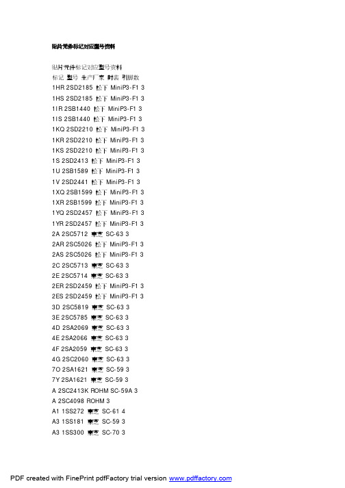
贴片元件标记对应型号资料贴片元件标记对应型号资料标记型号生产厂家封装引脚数1HR 2SD2185 松下MiniP3-F1 3 1HS 2SD2185 松下MiniP3-F1 3 1IR 2SB1440 松下MiniP3-F1 3 1IS 2SB1440 松下MiniP3-F1 3 1KQ 2SD2210 松下MiniP3-F1 3 1KR 2SD2210 松下MiniP3-F1 3 1KS 2SD2210 松下MiniP3-F1 3 1S 2SD2413 松下MiniP3-F1 3 1U 2SB1589 松下MiniP3-F1 3 1V 2SD2441 松下MiniP3-F1 3 1XQ 2SB1599 松下MiniP3-F1 3 1XR 2SB1599 松下MiniP3-F1 3 1YQ 2SD2457 松下MiniP3-F1 3 1YR 2SD2457 松下MiniP3-F1 3 2A 2SC5712 東芝SC-63 32AR 2SC5026 松下MiniP3-F1 3 2AS 2SC5026 松下MiniP3-F1 3 2C 2SC5713 東芝SC-63 32E 2SC5714 東芝SC-63 32ER 2SD2459 松下MiniP3-F1 3 2ES 2SD2459 松下MiniP3-F1 3 3D 2SC5819 東芝SC-63 33E 2SC5785 東芝SC-63 34D 2SA2069 東芝SC-63 34E 2SA2066 東芝SC-63 34F 2SA2059 東芝SC-63 34G 2SC2060 東芝SC-63 37O 2SA1621 東芝SC-59 37Y 2SA1621 東芝SC-59 3A 2SC2413K ROHM SC-59A 3 A 2SC4098 ROHM 3A1 1SS272 東芝SC-61 4A3 1SS181 東芝SC-59 3A3 1SS300 東芝SC-70 3A4 1SS319 東芝SC-61 4A4 1SS383 東芝4A5 1SS384 東芝SOT-343 4A5 1SS391 東芝SC-61 4A6 HN2S01F 東芝SC-74 6A6 HN2S01FU 東芝SC-88 6 A7 1SS402 東芝SOT-343 4A9 1SS294 東芝SC-59 3AL 2SA1971 東芝SC-63 3AL 2SC5307 東芝SC-63 3AN 2SC2532 東芝SC-59 3 AO 2SA2880 東芝SC-63 3 AQ 2SB766 松下MiniP3-F1 3 AR 2SB766 松下MiniP3-F1 3 AS 2SB766 松下MiniP3-F1 3 AU 2SB804 NEC SC-62 3AV 2SB804 NEC SC-62 3AW 2SB804 NEC SC-62 3AY 2SA2880 東芝SC-63 3B 2CS4081 ROHM 3B 2SC2412K ROHM SC-59A 3 B3 1SS184 東芝SC-59 3B3 1SS301 東芝SC-70 3B9 1SS311 東芝SC-59 3B9 1SS397 東芝SC-70 3BD 1SS271 東芝SC-59 3BE 1SV172 東芝BF 1SS268 東芝SC-59 3BG 1SS269 東芝SC-59 3BH 1SS295 東芝SC-59 3BO 2SA1200 東芝SC-63 3 BQ 2SB766A 松下MiniP3-F1 3 BR 2SB766A 松下MiniP3-F1 3 BS 2SB766A 松下MiniP3-F1 3 BU 2SD1005 NEC SC-62 3BU DA228K ROHM SC-59 3 BU DA228U ROHM SC-70 3 BV 2SD1005 NEC SC-62 3BW 2SD1005 NEC SC-62 3BY 2SA1200 東芝SC-63 3C 2SC2411K ROHM SC-59A 3C 2SC4097 ROHM 3C1 1SS352 東芝C1 1SS387 東芝C3 1SS226 東芝SC-59 3C9 1SS307 東芝SC-59 3CEO 2SC3325 東芝SC-59 3 CEY 2SC3325 東芝SC-59 3CG 2SA1163 東芝SC-59 3CK 2SD999 NEC SC-62 3CL 2SD999 NEC SC-62 3CM 2SD999 NEC SC-62 3CO 2SC2881 東芝SC-63 3CO 2SC4209 東芝SC-59 3CQ 2SB767 松下MiniP3-F1 3 CR 2SB767 松下MiniP3-F1 3 CY 2SC2881 東芝SC-63 3CY 2SC4209 東芝SC-59 3D 2SA1037KLN ROHM SC-59A 3 D3 1SS187 東芝SC-59 3DG 2SC2713 東芝SC-59 3DK 2SB798 NEC SC-62 3DL 2SB798 NEC SC-62 3DM 2SB798 NEC SC-62 3DO 2SA1201 東芝SC-63 3DQ 2SB789 松下MiniP3-F1 3 DR 2SB789 松下MiniP3-F1 3 DY 2SA1201 東芝SC-63 3E3 1SS190 東芝SC-59 3EK 2SD1001 NEC SC-62 3EL 2SD1001 NEC SC-62 3EM 2SD1001 NEC SC-62 3EO 2SC2882 東芝SC-63 3EQ 2SB789A 松下MiniP3-F1 3 ER 2SB789A 松下MiniP3-F1 3 EX 2SD2402 NEC SC-62 3EY 2SC2882 東芝SC-63 3EY 2SD2402 NEC SC-62 3EZ 2SD2402 NEC SC-62 3F 2SA1037K ROHM SC-59A 3 F 2SA1576 ROHM 3F3 1SS193 東芝SC-59 3F5 1SS250 東芝SC-59 3F5 1SS370 東芝SC-70 3F5 1SS403 東芝SOD-323 2F9 1SS321 東芝SC-59 3FK 2SB800 NEC SC-62 3FL 2SB800 NEC SC-62 3FM 2SB800 NEC SC-62 3FO 2SA1202 東芝SC-63 3FX 2SB1571 NEC SC-62 3FY 2SA1202 東芝SC-63 3FY 2SB1571 NEC SC-62 3FZ 2SB1571 NEC SC-62 3G3 1SS196 東芝SC-59 3G3 2SA1455K ROHM SC-59A 3 GK 2SD1615 NEC SC-62 3GL 2SD1615 NEC SC-62 3GM 2SD1615 NEC SC-62 3 GO 2SC2883 東芝SC-63 3 GP 2SD1615A NEC SC-62 3 GQ 2SD1615A NEC SC-62 3 GX 2SD2403 NEC SC-62 3GY 2SC2883 東芝SC-63 3GY 2SD2403 NEC SC-62 3GZ 2SD2403 NEC SC-62 3H9 1SS344 東芝SC-59 3HK 2SD1006 NEC SC-62 3HL 2SD1006 NEC SC-62 3HM 2SD1006 NEC SC-62 3 HO 2SA1203 東芝SC-63 3HP 2SD1007 NEC SC-62 3HQ 2SD1007 NEC SC-62 3HR 2SD1007 NEC SC-62 3HR 2SB956 松下MiniP3-F1 3 HS 2SB956 松下MiniP3-F1 3 HX 2SB1572 NEC SC-62 3HY 2SA1203 東芝SC-63 3HY 2SB1572 NEC SC-62 3HZ 2SB1572 NEC SC-62 3I9 1SS336 東芝SC-59 3IK 2SA1463 NEC SC-62 3IL 2SA1463 NEC SC-62 3IO 2SC3515 東芝SC-63 3IQ 2SB1073 松下MiniP3-F1 3 IR 2SC3515 東芝SC-63 3IR 2SB1073 松下MiniP3-F1 3 J 2SC2059K ROHM SC-59A 3J 2SC4099 ROHM 3J9 1SS337 東芝SC-59 3JO 2SA1384 東芝SC-63 3JR 2SK208 東芝SC-59 3JR 2SA1384 東芝SC-63 3K DA221 ROHM SC-75A 3K DA204U ROHM SC-70 3K DA204K ROHM SC-59 3K9 1SS348 東芝SC-59 3KA 2SC4409 東芝SC-63 3KD 2SC4541 東芝SC-63 3KK 2SB805 NEC SC-62 3KL 2SB805 NEC SC-62 3KM 2SB805 NEC SC-62 3KP 2SB806 NEC SC-62 3KQ 2SB806 NEC SC-62 3KR 2SB806 NEC SC-62 3L 2SC2412KLN ROHM SC-59A 3 L9 1SS349 東芝SC-59 3LA 2SA1681 東芝SC-63 3LD 2SA1736 東芝SC-63 3LK 2SD1000 NEC SC-62 3LL 2SD1000 NEC SC-62 3LM 2SD1000 NEC SC-62 3MK 2SB799 NEC SC-62 3 ML 2SB799 NEC SC-62 3 MM 2SB799 NEC SC-62 3 MO 2SC2873 東芝SC-63 3 MY 2SC2873 東芝SC-63 3 N9 1SS372 東芝SC-70 3 N9 1SS374 東芝SC-59 3 NA 2SK1273 NEC SC-62 3 NB 2SK1586 NEC SC-62 3 NC 2SK1485 NEC SC-62 3 ND 2SK1583 NEC SC-62 3 NE 2SK1585 NEC SC-62 3 NF 2SK1587 NEC SC-62 3 NG 2SK1588 NEC SC-62 3 NH 2SK1584 NEC SC-62 3 NI 2SK1586 NEC SC-62 3 NJ 2SK2111 NEC SC-62 3 NK 2SC2780 NEC SC-62 3 NL 2SC2780 NEC SC-62 3 NM 2SC2780 NEC SC-62 3 NO 2SA1213 東芝SC-63 3 NO 2SK1592 NEC SC-62 3 NP 2SK1593 NEC SC-62 3 NQ 2SK1959 NEC SC-62 3 NR 2SK1960 NEC SC-62 3 NS 2SK2109 NEC SC-62 3 NT 2SK2110 NEC SC-62 3 NV 2SK2112 NEC SC-62 3 NW 2SK2159 NEC SC-62 3 NX 2SK2857 NEC SC-62 3 NY 2SA1213 東芝SC-63 3 O9 1SS377 東芝SC-59 3 O9 1SS378 東芝SC-70 3 O9 1SS385 東芝SC-75 3 O9 1SS385F 東芝SC-81 3 OK 2SC3736 NEC SC-62 3 OL 2SC3736 NEC SC-62 3PA 2SJ179 NEC SC-62 3PB 2SJ197 NEC SC-62 3PC 2SJ199 NEC SC-62 3PD 2SJ205 NEC SC-62 3PE 2SJ207 NEC SC-62 3PF 2SJ208 NEC SC-62 3PH 2SJ206 NEC SC-62 3PO 2SC2884 東芝SC-63 3 PO 2SJ212 NEC SC-62 3PP 2SJ213 NEC SC-62 3PQ 2SJ355 NEC SC-62 3PR 2SJ356 NEC SC-62 3PY 2SC2884 東芝SC-63 3 QO 2SC2714 東芝3R12 UMR12N ROHM SC-88 6 R23 2SC3356 Q NEC SC-59 3 R24 2SC3356 R NEC SC-59 3 R25 2SC3356 S NEC SC-59 3 R9 1SS392 東芝SC-59 3R9 1SS393 東芝SC-70 3RQ 2SD1280 松下MiniP3-F1 3 RR 2SD1280 松下MiniP3-F1 3 RS 2SD1280 松下MiniP3-F1 3 S2 1SS315 東芝SC-59 3S9 1SS394 東芝SC-59 3SA 2SC2982 東芝SC-63 3SK 2SC3554 NEC SC-62 3SL 2SC3554 NEC SC-62 3SM 2SC3554 NEC SC-62 3 SO 2SA1162 東芝SC-59 3T9 1SS396 東芝SC-59 3TA 2SA1314 東芝SC-63 3TA 1SV231 東芝1-1E1A 2TB 2SA1314 東芝SC-63 3TC 2SA1314 東芝SC-63 3TE 2SD1702 NEC SC-62 3TF 2SD1702 NEC SC-62 3TL 2SC3617 NEC SC-62 3TM 2SC3617 NEC SC-62 3TQ 2SD1699 NEC SC-62 3TQ 2SD1119 松下MiniP3-F1 3 TR 2SD1699 NEC SC-62 3TR 2SD1119 松下MiniP3-F1 3 UK 2SC3618 NEC SC-62 3UL 2SC3618 NEC SC-62 3UM 2SC3618 NEC SC-62 3VK 2SD1950 NEC SC-62 3VL 2SD1950 NEC SC-62 3VM 2SD1950 NEC SC-62 3 VR 2SD968A 松下MiniP3-F1 3 VS 2SD968A 松下MiniP3-F1 3 VY 2SJ106 東芝SC-59 3W 2SD1383K ROHM SC-59A 3 W3 FMW3 ROHM 5X9 1SS398 東芝SC-59 3XK 2SD1614 NEC SC-62 3XL 2SD1614 NEC SC-62 3XM 2SD1614 NEC SC-62 3 XN 2SD1784 東芝SC-63 3 XR 2SD875 松下MiniP3-F1 3 XS 2SD875 松下MiniP3-F1 3 YB 2SK680A NEC SC-62 3YK 2SB1115 NEC SC-62 3YL 2SB1115 NEC SC-62 3YM 2SB1115 NEC SC-62 3YP 2SB1115A NEC SC-62 3 YQ 2SB1115A NEC SC-62 3 YQ 2SD874A 松下MiniP3-F1 3 YR 2SD874A 松下MiniP3-F1 3 YS 2SD874A 松下MiniP3-F1 3 Z7 2SK2549 東芝SC-63 3Z8 2SJ360 東芝SC-63 3Z9 2SJ465 東芝SC-63 3ZA 2SK2615 東芝SC-63 3ZB 2SK2963 東芝SC-63 3 ZC 2SK2964 東芝SC-63 3 ZD 2SK2992 東芝SC-63 3 ZE 2SJ508 東芝SC-63 3ZF 2SJ511 東芝SC-63 3ZG 2SK3471 東芝SC-63 3 ZK 2SB1114 NEC SC-62 3 ZL 2SB1114 NEC SC-62 3 ZM 2SB1114 NEC SC-62 3 ZO 2SA1182 東芝SC-59 3 ZQ 2SD874 松下MiniP3-F1 3 ZR 2SD874 松下MiniP3-F1 3 ZS 2SD874 松下MiniP3-F1 3 ZX 2SB1628 NEC SC-62 3 ZY 2SB1628 NEC SC-62 3 ZZ 2SB1628 NEC SC-62 3。
PSIM中文教程全解
PSIM®用户指南9版版本32010五月版权©2001-2010 Powersim公司保留所有权利。
本手册的任何部分不得复印或以任何形式或任何手段没有写转载公司的权限模型免责声明Powersim公司(“Powersim”)作出任何陈述或保证相对于此的充分性或准确性文档或它所描述的软件。
在任何情况下将模型或其直接或间接供应商承担任何任何性质的损害,但不限于,直接,间接,附带或相应的损害赔偿的任何字符包括,不限于,商业利润损失,数据,商业信息,或任何和所有其他商业损害或损失,或对任何损害赔偿超过清单价格的许可证的软件和文件.Powersim Inc.mailto:***************************内容1一般资料1.1引言11.2电路结构21.3软件/硬件需求31.4安装程序31.5模拟电路31.6组件参数规范和格式32电源电路组件2.1电阻电感电容器分支72.1.1电阻器、电感器和电容器,72.1.2变阻器82.1.3饱和电感82.1.4非线性元件92.2开关102.2.1二极管、LED、Zener Diode、和移民局10 2.2.2晶闸管和双向可控硅122.2.3 GTO和晶体管132.2.4双向开关152.2.5线性开关162.2.6开关门17座2.2.7单相开关模块192.2.8三相开关模块192.3耦合电感222.4变压器232.4.1理想变压器232.4.2单相变压器232.4.3三相变压器252.5磁元件262.5.1绕组262.5.2漏磁通路径272.5.3空气间隙272.5.4线性核心292.5.5 Saturable Core 292.6其他元素302.6.1运算放大器302.6.1.1理想运算放大器30我4章:2.6.1.2非理想运算放大器31 2.6.2并联稳压器TL431 32 2.6.3 Optocoupler 332.6.4 dv / dt的34块2.7热模块352.7.1设备数据库编辑器3542在数据库2.7.2二极管器件2.7.3二极管损耗计算43在数据库45 2.7.4 IGBT器件2.7.5 IGBT损耗计算47在数据库50 2.7.6 MOSFET器件2.7.6 MOSFET的损耗计算51 2.8电机驱动模块54机械系统54 2.8.1参考方向2.8.2直流机562.8.3感应机582.8.4感应电机饱和612.8.5无刷直流电机622.8.6同步机与外部激励66 2.8.7永磁同步电机682.8.8永磁同步电机饱和70 2.8.9开关磁阻电机732.9 MagCoupler Module 76 2.9.1 magcoupler DL 76块2.9.2 MagCoupler Block 77 2.10 magcoupler RT模块81 2.11机械元件和传感器85 2.11.1机械元件和传感器85 2.11.1.1恒转矩负载852.11.1.2恒功率负荷852.11.1.3恒速负荷862.11.1.4 Type Load将军86 2.11.1.5外部控制负荷87 2.11.2齿轮箱872.11.3机械耦合块882.11.4机电接口88块2.11.5速度/转矩传感器89 2.11.6位置传感器912.11.6.1绝对编码器912.11.6.2增量式编码器922.11.6.3解析器922.11.6.4霍尔效应传感器93 2.12可再生能源模型94II章节:- 32.12.1太阳能模块942.12.2风机973控制电路元件3.1传递函数块993.1.1比例控制器1003.1.2积分1003.1.3微分器1023.1.4比例积分控制器1023.1.5单极控制器1033.1.6修改PI控制器1033.1.7 3型控制器104在过滤块105内置3.1.83.2计算功能块1063.2.1 106夏季3.2.2乘数和Divider 1063.2.3平方根107块3.2.4指数/电力/对数功能块107 3.2.5均方根107块3.2.6绝对和符号功能块1083.2.7三角函数1083.2.8快速傅里叶变换块108 3.2.9最大/最小功能块109 3.3其他功能块1103.3.1比较器1103.3.2限制器1103.3.3梯度(dv/dt)限制器110 3.3.4梯形、方形块1113.3.5采样/保持111块3.3.6舍入块1123.3.7时间延迟块1123.3.8器1133.3.9 THD 114块3.4逻辑组件1153.4.1逻辑Gates 1153.4.2设置复位触发器1153.4.3 JK触发器1163.4.4 D触发器1173.4.5单稳态多谐振荡器117 3.4.6脉冲宽度计数器1183.4.7向上/向下计数器118 3.4.8 A/D和D/A转换器119 3.5数字控制模块120三2章:3.5.1零阶保持1203.5.2 Z传递函数方框121122 3.5.2.1积分器3.5.2.2微分器1233.5.2.3数字滤波器1233.5.3单位延迟1253.5.4量化块1263.5.5循环缓冲区1283.5.6卷积块1293.5.7内存读取块1293.5.8数据阵列1303.5.9栈1303.5.10多采样率系统1313.6 simcoupler模块1323.6.1设立在PSIM和Simulink 132在Simulink 133 3.6.2求解器的类型和时间步长的选取4其他组件4.1参数文件1374.2来源1384.2.1时间1384.2.2常数1384.2.3直流电源1384.2.4正弦源1394.2.5方波电源1394.2.6三角/锯齿来源1404.2.7步源1414.2.8分段线性源1424.2.9随机源1434.2.10数学函数源1434.2.11电压/电流控制的来源144 4.2.12非线性电压控制源145 4.3电压/电流传感器1464.4探头和146米4.5电压/电流范围1484.6初始值1504.7开关控制器1514.7.1开关控制器1514.7.2α控制器154.7.3 PWM控制器152查找表4.8功能块1544.8.1控制电源接口15块四章节:- 14.8.2变换块1544.8.2.1 ABC dq0变换155ABCα/β不能转化14.8.2.3α/β- dq变换14.8.2.4笛卡尔坐标变换1574.8.3数学功能块1574.8.4查找表1584.8.5 C座1604.8.6简化C座1614.8.7外部DLL模块1624.8.8嵌入式软件164块5分析规格5.1仿真控制1655.2交流分析1665.3参数扫描1686电路原理图设计6.1创建一个电路1716.2文件菜单1736.3编辑菜单1736.4视图菜单1746.5支路菜单1756.5.1创建在主电路176支路-6.5.2创建子电路内的支路1776.5.3连接支路-在主电路178电路的178 6.5.4其他功能6.5.4.1传递变量从主电路支路178 6.5.4.2定制电路图1796.5.4.3包括在PSIM 180子元素列表6.6模拟菜单1806.7选项菜单1836.8实用工具菜单1876.9管理PSIM图书馆1876.9.1创造一次图像1886.9.2添加新的子电路元件为图书馆189 6.9.3添加一个新的DLL元到图书馆191 v0章:7波形处理7.1文件菜单1937.2编辑菜单1947.3轴菜单1947.4屏幕菜单1957.5测量菜单1967.6分析菜单1977.7视图菜单1987.8选项菜单1987.9标签菜单1997.10出口数据1998错误/警告消息和其他模拟问题8.1模拟问题2018.1.1时间步长的选取2018.1.2传播延迟的逻辑电路2018.1.3界面之间的电源和控制电路2018.1.4 FFT分析2028.2错误/警告消息2028.3调试203指数205一一般信息1.1引言PSIM仿真软件1是专为电力电子与电机驱动器。
EPI流量计说明书.
A节简介和安装介绍你的主触摸™流量计包括流量传感元件,温度传感元件,桥式放大器/信号输出板,微处理器电路板,变送器外壳和探头支持或流量部分。
根据您的要求,可能是这些个别集成到一个流量变送器组件,或者你可能有一个额外的流量变送器信号处理器组装(远程电子)。
在这两种配置中,微处理器转换非线性输入信号从线性0-5 VDC4-20 mA输出流量变送器信号。
各种其他可选的通信协议,包括RS232/RS485,火线™红外模块,数据记录与EPICommunicator ™2.0和Modbus或HART兼容模块。
仪器的开箱你的主触摸™热式质量流量计是一种精密的电子流量仪表。
虽然这些流量计是坚固耐用的,他们应在交货时检查,以确保没有损害发生于运送途中。
如果经检查发现,损害已经发生,立即通知承运人,并把货物损坏索赔。
运输容器或箱子应谨慎处理,小心打开,以避免可能造成的损害的内容。
后容器被打开的内容,应仔细清除,并检查各个部分对照装箱单。
请注意,装箱清单会显示所有选项为您的仪器订购。
许多,如果不是全部,这些选项将被纳入流仪表本身并不会是单独的组件。
最后验证检查设备校准范围如流量计的文档上显示匹配你的采购订单规格。
如果您发现不符或有任何疑问,你是怎样领受,立即联系EPI。
电源要求电源要求主触摸™流量计“DC24”选项,为用户提供18至24伏特DC@250毫安。
主触摸™流量计“AC115”选项电源要求115 V AC,50/60赫兹标准,或220 V AC,50/60赫兹“AC230”选项。
如果管道是用来括电源输入线,它应该适合于该应用,导电性,和内连接外壳接地。
我们的建议电线尺寸为18佐治亚州的所有AC搁浅接线。
如果流量计包括一个远程电子组装,然后流量变送器电源提供连接到远程组件(见G部分对应的接线说明你的配置)。
十英尺的两导线连接电缆提供与远程组件。
如果更多的电缆是必需的,应替换为一个两线,双绞屏蔽电缆10'的长度。
爱普生晶振EG-2123CB低抖动表面声波(SAW)振荡器规格书

SAW 单元的极低抖动振荡器
规格(特征)
项目 输出频率范围 电源电压 储存温度 工作温度 频率稳定度 功耗 输出禁用电流 占空比 输出电压 (LV-PECL) VOL VOD dVOD VOS dVOS L_ECL L_LVDS VIH VIL tr / tf t_str 0.23 ps Max. 0.22 ps Max. 0.21 ps Max. 0.18 ps Max. 0.16 ps Max. 0.14 ps Max. 0.10 ps Max. H: 频率稳定度包含 符号 f0 VCC T_stg T_use f_tol ICC I_dis SYM VOH LV-PECL LVDS EG-2123CB P EG-2103CB P EG-2123CB L EG-2103CB L 100 MHz ~ 700 MHz 3.3 V 0.33 V 2.5 V 0.125 V 3.3 V 0.33 V 2.5 V 0.125 V -55 C ~ +125 C P:0 C ~ +70 C ,R:-5 C ~ +85 C ,S:-20 C ~ +70 C H: 100 10-6 30 mA Max. 60 mA Max. 2 mA Max. 15 mA Max. 45 % ~ 55 % 1.55 V Typ. 2.35 V Typ. VCC-1.025 V ~ VCC-0.88 V 0.80 V Typ. 1.60 V Typ. VCC-1.81 V ~ VCC-1.62 V 350 mV Typ, 247 mV ~ 454 mV 50 mV Max. 1.25 V Typ, 1.125 V ~ 1.375 V 150 mV Max. 50 100 70 % VCC Min. 30 % VCC Max. 400 ps Max. 10 ms Max. 0.27 ps Max. 0.24 ps Max. 0.23 ps Max. 0.19 ps Max. 0.16 ps Max. 0.14 ps Max. 0.10 ps Max. 条件 请联系我们以便获取其它可用频率的相关信息 裸存
RELM EPI 3101AV HF 无线电设备说明书
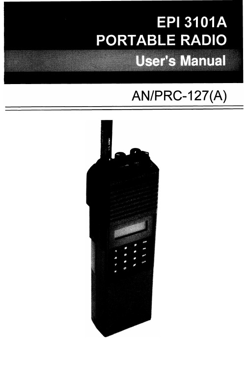
TABLE OF CONTENTS Introduction (1)Preparation For Use (2)Keyboard/Display Cover (2)Battery Installation (2)Antenna Installation (2)Radio Controls (3)Basic Operation (4)Detailed Operation (5)Display (5)Keyboard (5)Volume Control (5)Squelch Control (6)Channel Groups (6)PTT Switch (7)Code Guard Operation (8)Programming (9)Programming- Keyboard Method (9)Cloning (23)Programming From A Computer (26)Accessories (27)INTRODUCTIONThis manual covers the operation and programming procedures for RELM’s model EPI 3101AVHF Radio. The Radio provides two-way FM communication on up to 28 channels, over a frequency range of 136 to 160 MHz, with an RF output of 3 watts.This synthesized portable utilizes a microprocessor core allowing features and performance designed to meet the requirements of a commercial NDI NSUR as detailed in the Purchase Description, AN/PRC-127(A) Radio Set. Using the information in this manual will help assure optimum and proper performance from the Radio.The Radio Set consists of the EPI 3101A Radio and the following accessory items: LAAO126 Rechargeable Nickel-Cadmium Battery (2), LAA0312A Battery Charger, LAA0117 Battery Holder for 9 replaceable AA batteries, LAA0818A Flexible Antenna, LAA0203A External Speaker/ Microphone and LAA0445A Carrying Case. All of these items, except for the Radio, are shown on page 27.EPI 3101A User’s Manual1PREPARATION FOR USEKEYBOARD/DISPLAY COVERTo remove or install the Keyboard/Display Cover, remove the battery if installed. The Cover slides in grooves and latches at its bottom edge. BATTERY INSTALLATIONA.Battery packs are available as a rechargeable type (LAA0126) oras a non-rechargeable type (LAA01 17). Rechargeable battery packs can be charged separately or while attached to a radio.NOTE: For safety reasons, rechargeable battery packs are shipped uncharged or only partially charged. Therefore, a recharge-able battery pack should be properly charged before use.B.To install the battery pack, locate the center hub on the radio baseand place it in the recess of the battery pack. Position the pack at the 30” offset, seating two metal studs in their recess. Apply upward pressure to the pack while twisting the pack to its original position.The metal tab will click, locking the pack in position.C.To remove the battery pack, first turn the radio off. Then, as shownabove, push up the metal tab on the side of the case while twisting the battery pack approximately 30° and remove it from the radio.NOTE: All information programmed into the radio is maintained even when the battery pack is removed.D.Periodically check the contacts on the battery pack for dirt that mayprevent a good electrical contact with the charging base.WARNING:Do not dispose of a battery pack in fire.An explosion may occur.ANTENNA INSTALLATIONInsert the flexible helical-wound antenna (LAA0818A) into the Unit’s antenna connector and turn it clockwise until it is firmly seated.27-SEGMENT LIQUID CRYSTAL DISPLAYSPEAKERM I C R O P H O N ELCD DISPLAYK E Y B O A R D EPI 3101A User’s Manual3BASIC OPERATIONTRANSMITFunction - Used only in Programming ModeClear (Erase) - Used in Operational andSQUELCH CONTROLRotate the Squelch Control (CG-SQ) Knob clockwise from its detent (CG) position in order to hear any transmissions, regardless if they are tone or digital coded or not. This, in effect,. is the Radio’s MONITOR position. Turning the Squelch Control further clockwise until “noise” is heard permits the Volume Control to be adjusted to a desired level, even though an actual signal is not present.CHANNEL GROUPS510411312213114SELECT A GROUPGROUP NUMBER The Channel Selector knob has 14 positions. The Radio has 28 channels which are separated into two “groups” of 14 channels each. Group 01 is factory programmed for narrow channel (12.5kHz) FM reception. Channel Group 02 is programmed for wide channel (25 kHz) FMreception. Use Group 02 for proper communicationwith the original AN/PRC-127 Radio.P RESS THE #KEY on the keyboard to display the current Channel Group number. If it isn’t the desired Group, proceed to the next step.P RESS A NUMBER KEYfor the new Group number.P RESS THE ENTKEY or wait about 5 seconds; the radio returns to normal operation for the newgroup, and the channel corresponding to theChannel Selector’s position is displayed in theLCD.If an invalid number is selected (05 for example)when selecting a Channel Group, the LCD displaysnogrp05 (no Group 05) immediately if ENT ispressed, or in about 5 seconds if not pressed.Then, after 5 seconds, the radio returns to thepreviously selected group.6Rotate the Channel Selector knob to the desired channel. Please note that not all 14 channels may be programmed. Therefore, select only an authorized (programmed) channel for communication purposes.PTT SWITCHChCODE GUARD OPERATIONCode GuardTM, Tone or Digital, allows one radio or group of radios to be selectively called within a system. If the radio has been programmed with Code Guard, use the following receive and transmit instructions. CODE GUARD RECEIVETURN POWER ON by turning the Volume knobclockwise past the OFF detent.S ELECT A C ODE G UARD CHANNEL by turning theChannel Selector knob.A DJUST VOLUME by turning the Squelch knobclockwise until a rushing noise is heard, thenturning the Volume knob to a comfortable level.S ET C ODE G UARD MODE by turning the Squelchknob completely counterclockwise, past the detentto the CG position. A message will be heard onlywhen the proper Code Guard value is received.CODE GUARD TRANSMITT URN THE S QUELCH KNOB clockwise, off the detent.M ONITOR THE C ODE G UARD CHANNEL beforetransmitting.P RESS THE PTT (Push-To-Talk) switch if thechannel is not busy (signal is not present). Whenthe transmitter is activated, the LCD goes blank.R ESET THE S QUELCH KNOB to the Code Guardposition (CG) to receive only the messages withthe proper Code Guard value. During extendedtransmissions the squelch can be left open (offthe detent) until the exchange has ended.Code Guard is a trademark of BK Radio, Inc.8PROGRAMMINGThere are three different ways to program an EPI 3101A radio:A.It can be programmed and/or reviewed using its internal keyboard.This section of the manual describes that procedure.B.Another radio (MASTER) with the desired information can transferits programmed settings to the radio (SLAVE) by using a cloning cable, LAA0700. See “Cloning” on page 23.C.It can be programmed from a computer by using a special RS-232interface cable. That procedure is not described in this manual.See page 26 for more details.PROGRAMMING - KEYBOARD METHODRadios are shipped with a removable door covering the keyboard and display. Before programming or reviewing, remove the door. First, remove the battery pack if installed. Then, engaging the door just below the speaker grill, slide the door downward. Reinstall the battery pack. Make sure the battery pack is charged.1.Turn the radio on.2.Select the Channel Group to beprogrammed or reviewed.3.Press and hold the FCN key. Afterapproximately three seconds, the LCD willdisplay ---Id.4.Release the FCN key. The radio is now inthe password entry mode.5.Enter the six-digit Password Code.IMPORTANT: VVithout the correct PasswordCode, you cannot proceed with reviewingor programming. The same PasswordCode is used for both Channel Groups.New radios shipped from the factory areassigned the Password Code 000000.While entering the Password Code, thedisplay will not change, but a beep willsound for each key pressed. If thePassword Code is entered incorrectly, theradio will reset to normal operation. Tryagain, starting at step 3.EPI 3101A User’s Manual96.To keep the Password Code unchanged,press the ENT key and continue with normalradio programmingTo change the Password Code, press theFCN key and enter a new six-digit passwordcode. The’digits are now displayed as youenter them. The Password Code cancontain the digits 0 through 9, *, and #. The* is represented as a b and the # isrepresented as an A in the display.IMPORTANT: Do NOT use a 1 for the first digitof the Password Code - the radio willmalfunction. It will then require using acomputer program to correct the PasswordCode and put the radio back into normaloperating condition.If you make an errorwhile entering the newPassword Code, press the CLR key andtry again.7.Press the ENT key to store the newPassword Code and proceed to theprogramming mode. The display willchange to PROG Ch 0. The Radio is nowready for Reviewing and/or Programming. TO REVIEW GENERAL RADIO PERFORMANCE VARIABLES (CHANNEL 0):Channel 0 is the portion of the program that controls the general performance variables for each Group of 14 channels in a 28-channel radio. Thus, the Channel 0 settings for each Channel Group must be reviewed or programmed separately.NOTE: Settings listed as Group One Functions and Group Two Functions refer to reviewing or programming Function Groups,not the two Channel Groups 01 and 02.10Channel 0 Settings for each Channel Group include:Factory ProgramD e s c r i p t i o n Setting D i s p l a yID or Automatic Number Identification (ANI)’12345671234567 Transmit Timeout Timer disabled0 sec. Scan Delay Time disabled0.0 sec. Group One Functions 1-12345Battery Saver lnhibit 1-1 (See Note 3)disabled1-12345 Priority Scan Operation 1-2 &3disabled1-12345\I/ Priority Key Lockout 1-4enabled1-12345/I\\I/ Scan List Lockout 1-5enabled1-1for example, indicates that Function (l-1) is enabled and itscorresponding number(s) in the display is flashing. W h e n aFunction is disabled, its corresponding number(s) is steady. EPI 3101A User’s Manual1111.After entering the program mode,the display will show PROG Ch 0.2.Press CLR and then press the digit key(s) of the channel that needs to be reviewed. The display will show the channel to be reviewed.3.Press the FCN key. The display will show the receive frequency in MHz.4.Press the FCN key. The display will show the receive Tone Code Guard or Digital Code Guard (the value 0.0denotes carrier squelch). Digital Code Guard will be a three digit number preceded by a d in the display.DIGITAL CODEP R O G 1.Battery Saver Inhibit - If needed,press the 1 key to change the BatterySaver’s status.BATTERY SAVER ONREMINDER: If 1 is steady, theBattery Saver Inhibit is disabled, EPI 3101A User’s Manual152 & 3.4 ICHANNEL NOT CHANGEABLE SCAN LIST NOT CHANGEABLEFunctions 2 and 3 are used to definePriority Scan operation. SincePriority Scan is not available, both 2and 3 should be steady.PRI Key Lockout-When enabled (flashing) the PRI key will be locked out in the operating mode. Because the PRIORITY feature is not available, the 4 should be flashing.Scan List Lockout - VVhen enabled (flashing), the User will not be able to change the channels in the scan list. Since SCAN is not available,the 5 should be flashing.Once each function l-5 is set as desired, press ENT to store them into memory and automatically advance the program to the next section.If no changes have been entered,press FCN to advance to the next section.F.Miscellaneous Channel 0 Programming-GROUPTWO FUNCTIONSAfter Group 1 functions are set, the display will show PROG 2-12345for,I J NO RECEIVE FREQUENCY 1.Press 1, for example, and the displaywill show PROG Ch 1. This is theentry point for channel 1 values. 2.Press FCN. The display will showPROG RX and the ReceiveFrequency (in MHz) for channel 1.RX stands for Receive Frequency.If the channel has not beenprogrammed yet, the display willshow PROG RX 0.0.3.If the displayed frequency is correct,press FCN to advance to the nextvalue.To initially program the frequency orif a new frequency is desired, pressCLR followed by the digits of thedesired frequency from left to right.Then press ENT to store this , frequency and automatically advance to the next value.See Table 1 on page 18 for properfrequency increments.EPI 31OlA Usefs Manual17lOkHz(O-9)1kHz(0,2 or5)1kHz(O or 5)ITable 1. Proper Frequency Increments.184.After the Receive Frequency is set,the upper part of the display willshow PROG RX CG. This is theCode Guard value for Channel 1receive. Note: 0.0 indicates carriersquelch operation.If the displayed value is correct, pressFCN to advance to the next value.If a new value is desired, press theCLR key to reset the display to 0.0.Tone Code Guard is entered directly,using the digit keys (0 through 9).See pages 21 and 22 for properCode Guard values.Digital Code Guard is entered byfirst pressing CLR, then the # key,causing the letter d to appear,7xSELECTING A TONE CODE GUARDThe Tone Code Guard system (CTCSS) may be set for any frequency in the range of 67 to 250.3 Hz. However, since most systems adhere to the Electronic Industry Association (EIA) standards, tones should be selected from the following EIA list.In order to insure optimum performance tone selection for use on the same radio frequency (RF) channel or adjacent channels in the same coverage area should be made from one of the Groups A, B, or C as much as possible. RELM guarantees optimum receiver performance only if tone frequencies below 220 Hz are chosen.GROUP A GROUP B GROUP C67.0 77.0 88.5 *100.0 107.2 114.8 123.0 131.8 141.3*151.471.9146.274.4 162.282.5156.779.7 173.894.8167.985.4 186.2103.5“179.991.5 203.5100.9192.8218.1*118.8210.7233.6127.3225.7250.3136.5241.8*50/60 Hz power distribution systems could cause falsing.The assignments in a given area shall be made from one of the Groups A, B, or C as much as possible.EPI 3101A User’s Manual21SELECTING A DIGITAL CODE GUARDCodes for the Digital Code Guard system (CDCSS) may be chosen from the following list. For the performance or compatibility of Digital Code Guard systems, it is recommended that an operational test be made on the intended system before wholesale assignments are made.In some cases, either one or both the transmit and receive codes will require an inverted code* to operate with existing systems. This can be done during the code programming of the system.Usually, systems using direct unit to unit transmission (systems without mobile relays, repeaters, remote control, etc.) may use codes from the table. Systems with relays, etc. may use code variations for system control and operational efficiency. The system operator or engineer should be consulted regarding the operational requirement on such systems.023065 131 172 251 331 412 466 612 703 025071132 174 261 343 413 503 624 712 026072 134 205 263 346 423 506 627 723 031073 143 223 265 351 431 516 631 731 032074 152 226 271 364 432 532 632 732 043114 155 243 306 365 445 546 654 734 047115 156 244 311 371 464 565 662 743 051116 162 245 315 411 465 606 664 754 054125 165*NOTE: Inverted code is displayed with a "-" following the Digital Code’s value. See page 20 for an example.2289Press the * key on the MASTERradio keyboard. The display will flashPROG signifying that the radio isready to download its program to theCLONE.Press the FCN key on the MASTERradio keyboard. The program in theMASTER will then be downloadedto the CLONE. The CLONE willautomatically send back the programto the MASTER to verify a successfulcloning.10. If the download was successful, theMASTER’s display will resumeflashing PROG.A.To clone the other ChannelGroup, power down both radiosand go to Step 3, changing theChannel Group as required.B.If finished cloning, power downthe CLONE and disconnect thecloning cable. Normal radiooperation will occur on theCLONE’s next power up.11. If the download was not successful,the MASTER will display FAIL andmultiple beeps will follow. Failure ofdownloading can be due to:A. Improper connectionB.Failure to power up CLONEC.CLONE set in the programmingmodeNOTE: To stop the FAIL mode,press CLR, power down both radiosand try again, starting at step 1 onpage 23.24SPECIAL CLONING INSTRUCTIONSIt is possible to change Channel 0 values on the MASTER radio, hold them in a temporary memory, and download them to the CLONE without actually entering them into the permanent memory of the MASTER. This is convenient if sequential identification numbers are used to identify a series of portables in a radio system. Assuming that the frequencies,Code Guard values, and other CH 0 values are common for all radios in the system, but that the radio identification number should be unique to each radio, the following method would be used to clone additional radios for the system:123456Program the MASTER with allfrequencies, Code Guard values andChannel 0 values that will becommon to all radios.Advance the display to show theMASTER’s ID number (for example100)Press CLR; press 1,2, and 5.125 isnow only in temporary memory.Press *, connect the cloning cable tothe CLONE radio and download bypressing FCN. ID number 125 isnow stored in permanent memory ofthe CLONE.After download, press CLR.Disconnect the CLONE. TheMASTER radio display will showthat 125 is still being held in thetemporary memory of the MASTER.Press PRI. This will increment theID number one digit to 126.NOTE: Any new number can be entered at this point by pressingCLR and using the digit keys toenter the new number.EPI 3101A User’s Manual 257.Press *. Connect the cloning cableto the next CLONE radio anddownload by pressing FCN.8.Any number of radios can be codedwith different or sequential IDnumbers using this technique. TheID number in the permanent memoryof the MASTER will remainunchanged as 300.PROGRAMMING FROM A COMPUTERProgramming the radio from an IBM compatible computer, using the LAA0725 Interface Cable, is covered in a separate programming manual. The manual is included with the programming software. Contact RELM Communications, Inc. to order the interface cable and software. Specify the program is for the EPI 3101A Radio.26Helical-wound flexible antenna that covers the entire range of frequencies that can be programmed into the EPI 3101A Radio.LAA0445A Carrying CaseThis textile case is built to provide proper protection while keeping the radio at your side.LAA0203A Speaker/MicrophoneThis light weight speaker/microphone clips securely to collar or lapel, offering the convenience of easy communications without removing the radio from your belt. To install the LAA0203A:1.Lift away the protective cover from the Accessory connector andEarphone jack. See Radio’s side view on page 3 for theirlocation. The protective cover can not be completely removedsince it is permanently attached near the flexible antenna’sconnector.2.Carefully install the Speaker/Microphone’s connector assemblyinto the Accessory and Earphone connectors.3.Screw in the assembly’s retaining bolt until finger tight. Do notovertighten.NOTE: VVhen the LAA0203A is removed, the protective cover should be reinstalled so that the various electricalconnections are not exposed to dust, dirt, rain, etc.28RELM Communications, Inc. 7505 Technology Drive West Melbourne, FL 32904 Telephone: (407) 984-1414 FAX: (407) 676-4403。
B型编程器使用说明书
B型编程器使用说明书(使用前请仔细阅读)上海奥莉生电子有限公司2011-1-8目录1概述 (3)2使用说明 (3)2.1 编程器器件位置图 (3)2.2适用芯片型号及拨码开关选择 (4)2.3芯片放置 (4)2.3.1 烧录C61F183/ebike0x/iCooker01 (4)2.3.2 烧录C61F187 (5)2.3.3 烧录C61F121/133/23 (5)2.3.4 烧录C61F120/132/21 (5)2.4拨码开关功能分配 (5)3操作步骤 (6)1概述B 型编程器主要功能为从母片拷贝程序存储器、数据存储器、配置字到待编程片。
另外还可以对待编程片进行晶振校准(具体根据用户对拨码开关和跳线帽的设置)。
2使用说明2.1 编程器器件位置图39图1 编程器器件位置示意图1.+12V 电源插座2.电源开关3.电源指示灯(红色)4.状态指示灯(绿色)5.状态指示灯(红色)6.备用按键7.拨码开关8.跳线帽(晶振校准时才更改)9.母片插座10.待编程片插座11.ICSP编程接口2.2适用芯片型号及拨码开关选择编程器适用型号与拨码开关对应关系如表1所示。
注:1.拨码开关第1 位是FLASH空间加密选择位,ON:加密FLASH,OFF:不加密FLASH2.拨码开关第2 位是EEPROM空间加密选择位,ON:加密EEPROM,OFF:不加密EEPROM3.拨码开关第8位是芯片选择位,编程器上电前必须选择,否则会出错。
若被编程片为8 /14脚该位选择ON,若为28/32/40脚该位选择OFF。
2.3芯片放置母片放入母片插座,待编程片放入待编程片插座,母片与待编程片放入插座的位置一致。
2.3.1烧录C61F183/ebike0x/iCooker01母片为PIC16F883/8872.3.2 烧录C61F187母片为PIC16F8872.3.3 烧录C61F121/133/23母片为PIC16F630/676/6842.3.4 烧录C61F120/132/21母片为PIC12F629/675/6832.4拨码开关功能分配拨码开关如图2所示,下面的1代指拨码开关第1位,以此类推。
EPIP30 系列智能控制器 说明书
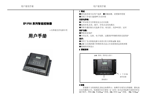
LCD数码、图形显示窗口接线端口太阳标志,表示白天和晚上光控启动点的状态;)择任一种方式;)蓄电池符号,内部条状图形表示充放电状态及当前容量百分比如果系统处于放电状态,则蓄电池的方式显示蓄电池处于放电状态;保险负载状态标志蓄电池状态充电控制方式参数及参数单位显示区负载控制方式标志闪烁,充电恢复后停止闪烁;直流输出符号;负载图标,表示负载状态及故障状态;常显,当允许输出为“开”状态时,显示负载状态;过载时,负载符号K4负载和闪电符号闪烁次短路保护动作,需用户检查负载线路,参数单位:LCD池容量,符号显示,充电符号“”闪烁,表示当前可以修改充电控制方号及充电符号“”闪烁时,按一下显示,恢复原控制方式,并返回到参量选择状态;在“SET”符号显示及太阳符号“符号闪烁,表示现在可以确认设置光启动电压,再按一下当出现太阳图形在天黑自动的启动负载输出,白天自动关闭输出。
太阳,表示光控+延时,控制器会自动检测光强弱,在天黑自动的启动负载输出,同时根据所选择的工作时长自动关闭负时钟无图形显示,表示手动控制;3.6时间调整操作:包括实时时间、延时时间和定时开关时间;●在负载控制为手动、光控模式下,只显示调整实时时间。
●在光控+延时模式下,可以调整实时时间和延时关闭小时数。
●定时模式下可以调整实时时间和定时开、关对应的小时、分钟数据,用户首次使用,默认的控制时间数据均为0,所以在首次连接使用时要设置相应的时间,之后,控制器按照最后一次的设置参数工作;1)在显示需要调整的时间时,按一下K3,“SET”符号及右下角的H:M 符号中的H闪烁,表示可以修改小时数据;2)通过K1/K2在0~23内调整数据;3)再按一下K3,保存小时数据并切换到修改分钟数据--“SET”符号及右下角的H:M符号中的M闪烁;4)通过K1/K2在0~59间调整数据;5)再次按K3保存修改数据,返回到选择状态—显示“SET”不闪烁;6)如果不保存更改,则按K4,返回到选择状态—显示“SET”不闪烁;3.7光控测试在浏览状态下,同时按下K1和K2键,放开后右侧太阳闪烁,控制器进入测试模式:光电池输入端加低于5V的电压,控制器开通输出光电池输入端加高于7V的电压,控制器关断输出如果符合上述现象,说明控制器光控功能正常,按K4键退出测试模式,返回浏览状态5安全及保护本控制器具有过压、过流、短路、反接等全保护功能,具有TVS防雷保护,并且过压、过流、短路保护在LCD上具有告警指示。