ACL_in_Practice
仁爱英语八年级下各单元短语归纳完整版

仁爱英语八年级下各单元短语归纳集团标准化办公室:[VV986T-J682P28-JP266L8-68PNN]Unit5TopicOne1.lookexcited看起来兴奋,激动2.feelhappy/disappointed感到高兴/失望3.tastedelicious/good尝起来美味4.soundwonderful/sweet/great听起来精彩/甜美/好,不错5.smellterrible闻起来恶心6.gomad/bad发疯/变坏7.turngreen/yellow变成绿色/黄色8.bepopularwithsb.受某人欢迎9.seem(tobe)unhappy似乎不高兴10.seemtodosth.似乎做,好像做11.gotothemovies=gotoseethemovie去看电影12.invite/asksbtodosth邀请某人做某事13.invitesb.to+sp.邀请某人去/参加…14.oneof+最高级+pl.最…之一15.preparesthforsb=preparesb.sth.为某人准备好某事16.preparetodosth.准备做17.saythanks/hello/sorry/goodbyetosb向某人说声谢谢/你好/抱歉/再见18.Whatashame/pity.真遗憾。
19.get/buytheticketto/for买到…的票20.beabletodo=can/coulddo能够做…21.willbeabletodo将会做…22.onthe/one’sway to在去往…的路上23.onthewayhome/here/there在回家/去这儿/那儿的路上24.rightnow/away=atonce立即,马上25.feel/besorryfor(doing)sth为(做)某事感到抱歉/遗憾/难过26.beangrywithsb.对某人生气27.justnow=amomentago刚才(用于过去时)28.carefor=takecareof=lookafter照顾29.becauseof+n.因为…,由于…30.because+句子因为…,由于…31.cheersbup=makesb.Happy使…兴奋起来32.atlast=intheend=finally最后,最终33.attheendof…在…的末尾/尽头34.atfirst起初,开始smilingfaces笑脸35.noisychildren吵闹的孩子们36.lovelysongs活泼的歌曲37.livealone独居be/feellonely感到孤独38.teachsb.todosth.教某人做39.teachoneselfsth.=learnsth.byoneself自学…eintobeing=beborn出现,形成41.fallinto落入,掉入lookfor寻找42.everywhere=hereandthere到处43.bewithahistoryof200years=haveahistoryof200years=have200 yearsofhistory有着两百年的历史eintobeing=beborn形成efrom=befrom来自46.moreandmore+n./原级越来越来…47.be/becomeinterestedin(doing)sth.对…感兴趣48.makepeacewithsb与某人和解49.findawaytodo/ofdoingsth.找到做…的方法50.Itseems/seemedthat+句子。
LTE_3GPP_36.213-860(中文版)
3GPP
Release 8
3
3GPP TS 36.213 V8.6.0 (2009-03)
Contents
Foreword ...................................................................................................................................................... 5 1 2 3
Internet
Copyright Notification No part may be reproduced except as authorized by written permission. The copyright and the foregoing restriction extend to reproduction in all media.
© 2009, 3GPP Organizational Partners (ARIB, ATIS, CCSA, ETSI, TTA, TTC). All rights reserved. UMTS™ is a Trade Mark of ETSI registered for the benefit of its members 3GPP™ is a Trade Mark of ETSI registered for the benefit of its Members and of the 3GPP Organizational Partners LTE™ is a Trade Mark of ETSI currently being registered for the benefit of i ts Members and of the 3GPP Organizational Partners GSM® and the GSM logo are registered and owned by the GSM Association
GSMR接口需求规范

ERTMS/ETCS – Class 1GSM-R InterfacesClass 1 RequirementsREF : SUBSET-093ISSUE : 2.3.0DATE : 10-Oct-2005Company Technical Approval Management approval ALCATELALSTOMANSALDO SIGNALBOMBARDIERINVENSYS RAILSIEMENS1. M ODIFICATION H ISTORYIssue NumberDateSection Number Modification / Description Author0.1.0 (8-Aug-02) Creation based on subset052LK0.1.1 (8-Aug-02) All Minor editorial changes LK0.1.1ec All englishcheck JH0.2.0 (9-Sep-02) 3., 4.2, 4.1, 6.3, 7.2,8.2 Updated after email discussionLK0.3.0 (24-Oct-02) All Updated after FlorencemeetingLK+TS0.4.0 (14-Nov-02) All Updated after LondonmeetingLK0.5.0 (5-Dec-02) 4.2, 5.6.1, 6.2, 7.1,7.3, 9.2 Updated after Berlin meetingLK0.6.0 (12-Dec-02) 3., 6.3., 10.4.3 Email comments included TS+LK2.0.0 (12-Dec-02) Erroneous versionnumber 2.2.0correctedFinal issue LK2.1.0 (28-March-03)3.1.1.1, 6.3.1.3,7.1.1.1, 8.1.1.1 Update acc. to super group commentsLK2.2.0 (28-March-03) - Final version LK2.2.2.31-03-03 Versionnumberchangedfor release to the usersGroupWLH2.2.3 (12-June-03) All Update after Brussels mtg.and GSM-R Op. grp.commentsLK2.2.4 (26-June-03) editorial Draft release to UsersGroupJH2.2.5 - FormalreleaseJH 2.2.5.1 4.2, 6.2, 6.3, new 6.4 Update after Paris mtg. andGSM-R Op. grp. commentsLK2.2.5.2 Various update after further GSM-ROp grp reviewJH2.2.5.3 cleanversion JH 2.2.5.4 6.4 Updated after further GSM-R Op grp requestRB2.2.6 CleanversionRB2.2.6 revA (31-Jan-05) 4.2, 6.3, 6.4, Annex A Proposal for QoS parametervaluesLK2.2.6 revB (14-Feb-05) 6.3, 6.4, Annex A Updated after QoSmeeting#6 BrusselsLK2.2.6 revC (24-Feb-05) 6.3, 6.4, Annex A,Annex B added Updated during BerlinmeetingLK2.2.6 revD (25-Feb-05) 6.2, 6.3.5, 10.3, 10.5.2 Email comments inserted LK2.2.6 revE (6-Apr-05)3.1., 3.2,4.1,5.1,6.3,10.1, 10.3, 10.5, 10.7 Updated after QoSmeeting#7 BrusselsLK2.2.6 revF (25-Apr-05)3.1,4.1,5.1,6.3, 6.4,10.1, 10.3, 10.5, 10.6,10.7Edinburgh meeting TS+LK2.2.6revG (20-May-05)3.1, 5.1, 6.3, 6.4, 8.2 Changes according toBrussels meetingLK2.2.6revH (1-Sep-05) 4.1, 5.1, 6.3, 6.4, 7.2,10.3, 10.4, 10.5 Comments from SG andEEIGLK2.2.6revI (8-Sep-05) 5.1, 6.3, 6.4, 10.4 Zürich meeting PL+LK 2.3.0 (10-Oct-05) update for issue JH2. T ABLE OF C ONTENTS1.M ODIFICATION H ISTORY (2)2.T ABLE OF C ONTENTS (4)3.R EFERENCES (6)3.1Normative Documents (6)3.2Informative Documents (7)4.T ERMS AND DEFINITIONS (8)4.1Abbreviations (8)4.2Definitions (9)5.G ENERAL (10)5.1Scope of this document (10)5.2Introduction (10)6.E ND-TO-END SERVICE REQUIREMENTS TO GSM-R NETWORKS (12)6.1Data bearer service requirements (12)6.2Additional services (12)6.3Quality of Service requirements (13)6.3.1General (13)6.3.2Connection establishment delay (14)6.3.3Connection establishment error ratio (14)6.3.4Transfer delay (15)6.3.5Connection loss rate (15)6.3.6Transmission interference (15)6.3.7GSM-R network registration delay (16)6.4Summary of QoS requirements (16)7.R EQUIREMENTS TO FIXED NETWORK INTERFACE (17)7.1Foreword (17)7.2Interface definition (17)7.3Communication signalling procedures (17)8.R EQUIREMENTS TO MOBILE NETWORK INTERFACE (18)8.1Foreword (18)8.2Interface definition (18)9.A NNEX A(I NFORMATIVE) TRANSMISSION INTERFERENCE AND RECOVERY (19)9.1General (19)9.2Transmission interference in relation to HDLC (19)10.A NNEX B(INFORMATIVE)J USTIFICATION OF Q O S PARAMETER VALUES (22)10.1General (22)10.2Connection establishment delay (22)10.3Connection establishment error ratio (22)10.4Transfer delay (23)10.5Connection loss rate (23)10.5.1QoS targets (23)10.5.2Conclusions (24)10.6Transmission interference (24)10.7Network registration delay (26)3. R EFERENCESDocuments3.1 Normative3.1.1.1 This document list incorporates by dated or undated references, provisions from otherpublications. These normative references are cited at the appropriate place in the textand the publications are listed hereafter. For dated references, subsequentamendments to or revisions of any of these publications apply to this document onlywhen incorporated in it by amendment or revision. For undated references the latestedition of the publication referred to apply.Reference DateTitleU-SRS 02.02 ERTMS/ETCS Class 1; Subset 026; Unisig SRS, version 2.2.2 Subset 037 07.03 ERTMS/ETCS Class 1; Subset 037; EuroRadio FIS; Class1requirements, version 2.2.5EIRENE FRS 10.03 UIC Project EIRENE; Functional Requirements Specification.Version 6.0, CLA111D003EIRENE SRS 10.03 UIC Project EIRENE; System Requirements Specification.Version 14.0, CLA111D004ETS 300011 1992 ISDN; Primary rate user-network interface; Layer 1 specificationand test principlesETS 300102-1 1990 ISDN; User-network interface layer 3; Specification for basiccall controlETS 300125 1991 ISDN; User-network interface data link layer specificationsGSM04.21 12.00 Rate Adaptation on the MS-BSS Interface, v.8.3.0GSM 07.0711.98 ETSI TS 100916; Digital cellular telecommunications system(Phase 2+); AT command set for GSM Mobile Equipment (ME),GSM TS 07.07 version 6.5.0 Release 1997ITU-T V.24 02.00 List of definitions for interchange circuits between data terminalequipment (DTE) and data circuit-terminating equipment (DCE)ITU-T V.25ter 07/97 Serial asynchronous dialling and controlITU-T V.110 02.00 Support of data terminal equipments (DTEs) with V-series typeinterfaces by an integrated services digital network (ISDN) EuroRadio FFFIS 09.03 UIC ERTMS/GSM-R Unisig; Euroradio Interface Group; RadioTransmission FFFIS for Euroradio; A11T6001; version 12O-2475 09.03 UIC ERTMS/GSM-R Operators Group; ERTMS/GSM-R Qualityof Service Test Specification; O-2475; version 1.0Documents3.2 InformativeTitleReference DateEEIG 04E117 12.04 ETCS/GSM-R Quality of Service - Operational Analysis, v0.q(draft)ERQoS 08.04 GSM-R QoS Impact on EuroRadio and ETCS application,Unisig_ALS_ERQoS, v.0104. T ERMS AND DEFINITIONS4.1 AbbreviationsAT ATtention command setATD AT command DialB channel User channel of ISDNB m channel User channel of GSM PLMN on the air interfaceBRI Basic Rate InterfaceByte 1 start bit + 8 data bits + 1 stop bitDCE Data Circuit EquipmentDCD Data Carrier DetectD channel Control channel of ISDND m channel Control channel of GSM PLMN on the air interfaceDTE Data Terminal EquipmenteMLPP enhanced Multi-Level Precedence and Pre-emptionFIS Functional Interface SpecificationGPRS General Packet Radio Service (a phase 2+ GSM service) GSM-R Global System for Mobile communication/RailwayHDLC High level Data Link ControlISDN Integrated Services Digital NetworkMLPP Multi-Level Precedence and Pre-emption (ISDN service) MOC Mobile Originated CallMS Mobile Station (a GSM entity)Termination/Terminated MT MobileMTC Mobile Terminated CallMTBD Mean Time Between DisturbanceUnitOBU On-BoardPLMN Public Land Mobile NetworkPRI Primary Rate InterfaceQoS Quality of ServicesRBC Radio Block CentreT TI Duration of Transmission Interference periodT REC Duration of Recovery periodUDI Unrestricted Digital4.2 Definitions4.2.1.1 Definitions for the purpose of this specification are inserted in the respective sections.5. G ENERAL5.1 Scope of this document5.1.1.1 The scope of this document is to specify the Radio Communication Systemrequirements to the GSM-R network services (including fixed side access) andinterfaces and also the pre-requisites to be fulfilled by GSM-R networks and ETCSinfrastructures. Presently the requirements for high-speed lines are covered,requirements for conventional lines may be included in future versions of thisdocument.5.1.1.2 The data transmission part of the communication protocols is fully described in theEuroRadio FIS [Subset 037].5.1.1.3 The Radio Transmission FFFIS for EuroRadio [EuroRadio FFFIS] specifies thephysical, electrical and functional details related to the interfaces.5.1.1.4 All requirements apply to GSM-R unless indicated otherwise .5.2 Introduction5.2.1.1 The definition of the GSM services and associated physical and communicationsignalling protocols on the air interface are fully standardised in the specificationsproduced by the ETSI GSM Technical Committee for the public GSM implementationas well as for the GSM-R. Additionally, some railway specific services are alsospecified in the EIRENE SRS. However, in both cases, not all are required for ERTMSclass 1 system definition.5.2.1.2 The following ETSI GSM phases 1/2/2+ services are required:a) Transparent data bearer serviceb) Enhanced multi-level precedence and pre-emption (eMLPP).5.2.1.3 Other ETSI GSM phases 1/2/2+ services are not required for Class 1. These are thefollowing :a) GSM supplementary services:• Call forwardingb) General packet radio service (GPRS)5.2.1.4 Other ETSI GSM phases 1/2/2+ services are not required. Examples of these are thefollowing :a) Non-transparent data bearer serviceb) GSM supplementary services:• Line identification•Call waiting and hold• Multiparty•Closed User Group•Advice of charge• Call Barringc) Short message service point to point or cell broadcastd) Voice broadcast servicee) Voice group call service5.2.1.5 The following EIRENE railway specific service [EIRENE SRS] is required:a) Location dependent addressing5.2.1.6 The following EIRENE specific services [EIRENE SRS] are not required :a) Functional addressingb) Enhanced location dependent addressingc) Calling and connected line presentation of functional identitiesd) Emergency callse) Shunting modef) Multiple driver communications6. E ND-TO-END SERVICE REQUIREMENTS TO GSM-RNETWORKS6.1 Data bearer service requirements6.1.1.1 For the transmission of information between OBU and RBC, the EuroRadio protocoluses the bearer services of a GSM-R network. The service provider makes these databearer services available at defined interfaces.6.1.1.2 The data bearer services are described as data access and transfer in the GSMnetwork from Terminal Equipment (TE) on the mobile side (i.e. OBU) to a networkgateway interworking with Public Switched Telephonic Network (PSTN) or IntegratedServices Digital Network (ISDN) on the fixed side (i.e. RBC).6.1.1.3 The following features and attributes of the required bearer service shall be provided:a) Data transfer in circuit switched modeb) Data transfer allowing multiple rate data streams which are rate-adapted[GSM04.21] and [ITU-T V.110]c) Unrestricted Digital Information (UDI) – only supported through ISDN interworking(no analogue modem in the transmission path)d) Radio channel in full ratee) Transfer of data only (no alternate speech/data)f) Transfer in asynchronous transparent modeg) The required data rates are listed in the following table:Bearer service Requirement24. Asynchronous 2.4 kbps T O25. Asynchronous 4.8 kbps T M26. Asynchronous 9.6 kbps T MT: Transparent; M: Mandatory; O: OptionalTable1 GSM-R bearer servicesservices6.2 Additional6.2.1.1 The following supplementary services shall be provided:a) Enhanced multi-level precedence and pre-emption.b) The selection of a particular mobile network shall be possible on-demand.6.2.1.2 The priority value for command control (safety) shall be assigned to according to[EIRENE FRS §10.2] and [EIRENE SRS §10.2].6.2.1.3 The following railway specific service shall be provided by GSM-R networks:a) Location dependent addressing based on the use of short dialling codes inconjunction with cell dependent routing.6.3 Quality of Service requirements6.3.1 General6.3.1.1 As an end-to-end bearer service is used, a restriction of requirements on the servicequality placed on the air interface is not sufficient.6.3.1.2 End-to-end quality of service has to be considered at the service access points.6.3.1.3 The service access points are:•the service access points to the signalling stack for the establishment or release of a physical connection,•the service access points to the data channel.6.3.1.4 The network shall be able to support transparent train-to-trackside and trackside-to-train data communications at speeds up to 500 km/h e.g. in tunnels, cuttings, onelevated structures, at gradients, on bridges and stations.6.3.1.5 The network shall provide a Quality of Service for ETCS data transfer that is at least asgood as listed below1. The parameters are valid for one end-to-end connection for onetrain running under all operational conditions.6.3.1.6 The required QoS parameters shall not depend on network load.6.3.1.7 These performance figures reflect railway operational targets [EEIG 04E117].6.3.1.8 Note: A justification of the performance figures is given by Annex B.6.3.1.9 QoS requirements are specified independently of the method of measurement (refer to[O-2475] for specification of testing).6.3.1.10 Conventional line quality of service requirements may be included in future versions ofthis document. Also the values may not be applied at all locations and times (e.g.discontinuous radio coverage at some locations).6.3.1.11 Given the performance constraints of GSM-R, pre-conditions may be necessary tomeet the railway operational targets of [EEIG 04E117]. If different operational QoStargets are required, then other pre-conditions on ETCS application may be necessary.1 Early experience suggests that GSM-R performance can be better than these parameters suggest, after network optimisation and tuning.Such a case is not covered by this specification and this aspect of ETCS SystemPerformance becomes the responsibility of whoever specifies different operationaltargets.6.3.2 Connection establishment delay6.3.2.1 Connection establishment delay is defined as:Value of elapsed time between the connection establishment request and theindication of successful connection establishment.6.3.2.2 In case of mobile originated calls, the delay is defined between the request bycommand ATD and indication by the later of the two events response CONNECT ortransition of DCD to ON.6.3.2.3 The connection establishment delay of mobile originated calls shall be <8.5s (95%),≤10s (100%).6.3.2.4 Delays>10s shall be evaluated as connection establishment errors.6.3.2.5 The required connection establishment delay shall not depend on user data rate of theasynchronous bearer service.6.3.2.6 The required connection establishment delay is not valid for location dependentaddressing.6.3.3 Connection establishment error ratio6.3.3.1 The Connection establishment error ratio is defined as:Ratio of the number of unsuccessful connection establishment attempts to the totalnumber of connection establishment attempts.6.3.3.2 “Unsuccessful connection establishment attempt” covers all possible types ofconnection establishment errors caused by end-to-end bearer service.6.3.3.3 Connection establishment delays >10s shall be evaluated as connection establishmenterrors.6.3.3.4 The GSM-R networks should be designed in such a way, that at least two consecutiveconnection establishment attempts will be possible (pre-condition on GSM-Rnetworks), e.g. regarding GSM-R radio coverage related to maximal possible trainspeed.6.3.3.5 If the operational QoS targets of [EEIG 04E117] are wanted, then the ETCSinfrastructure should be designed in such a way, that at least two consecutiveconnection establishment attempts will be possible (Recommended pre-condition forETCS infrastructure).6.3.3.6 The connection establishment error ratio of mobile originated calls shall be <10-2 foreach attempt .6.3.3.7 Note: entry into Level 2 is of particular importance; commonly, a time of 40s may berequired in the case the GSM-R mobile station is already registered with the GSM-Rnetwork (see [ERQoS]).6.3.4 Transfer delay6.3.4.1 The end-to-end transfer delay of a user data block is defined as:Value of elapsed time between the request for transfer of a user data block and theindication of successfully transferred end-to-end user data block6.3.4.2 The delay is defined between the delivery of the first bit of the user data block at theservice access point of transmitting side and the receiving of the last bit of the sameuser data block at the service access point of the receiving side.6.3.4.3 The end-to-end transfer delay of a user data block of 30 bytes shall be ≤0.5s (99%).6.3.5 Connection loss rate6.3.5.1 The Connection loss rate is defined as:Number of connections released unintentionally per accumulated connection time.6.3.5.2 The requirements for connection loss rate varies depending on ETCS system variablessuch as T_NVCONTACT and the possible train reactions after connection loss (seesection 10.5).6.3.5.3 If the operational QoS-targets of [EEIG 04E117] are wanted, then the ETCSinfrastructure should be designed in such a way, that at least the following conditionsare fulfilled (Recommended pre-condition for ETCS infrastructure):• T_NVCONTACT ≥ 41s and• M_NVCONTACT different to train trip and• a new MA reach the OBU before standstill.6.3.5.4 If the connection establishment error ratio is <10-2, then the connection loss rate shallbe <10-2/h.6.3.6 Transmission interference6.3.6.1 A transmission interference period T TI is the period during the data transmission phaseof an existing connection in which, caused by the bearer service, no error-freetransmission of user data units of 30 bytes is possible.6.3.6.2 A transmission interference happens, if the received data units of 30 bytes deviatepartially or completely from the associated transmitted data units.6.3.6.3 The transmission interference period shall be < 0.8s (95%), <1s (99%).6.3.6.4 An error-free period T Rec shall follow every transmission interference period to re-transmit user data units in error (e.g. wrong or lost) and user data units waiting to beserved.6.3.6.5 The error-free period shall be >20s (95%), >7s(99%).6.3.7 GSM-R network registration delay6.3.7.1 The GSM-R network registration delay is defined as:Value of elapsed time from the request for registration to indication of successfulregistration by +CREG response.6.3.7.2 The GSM-R network registration delay shall be ≤30s (95%), ≤35s (99%).6.3.7.3 GSM-R network registration delays > 40 s are evaluated as registration errors.6.4 Summary of QoS requirements6.4.1.1 Table 2 contains the summary of QoS requirements at GSM-R interface.QoS Parameter Value (see 6.3) Connection establishment delay of mobile< 8.5s (95%), ≤10s (100%) originated callsConnection establishment error ratio <10-2≤ 0.5s (99%)Maximum end-to-end transfer delay (of 30 bytedata block)Connection loss rate ≤ 10-2 /hTransmission interference period < 0.8s (95%), <1s (99%)Error-free period >20s (95%), >7s(99%)Network registration delay ≤30s (95%), ≤35s (99%), ≤40s (100%)Table 2 Summary of QoS requirements7. R EQUIREMENTS TO FIXED NETWORK INTERFACE7.1 Foreword7.1.1.1 This part of the specification does not define mandatory requirements forinteroperability. It is a preferred solution, in case interchangeability between tracksideRBC and access point to the fixed network is required for a given implementation.7.1.1.2 This section gives only limited information. [EuroRadio FFFIS] must be used for fullcompliance.7.1.1.3 Note: The requirements to fixed network interface refer to a set of ETSI specifications[ETS 300011, ETS 300125, ETS 300102-1]. This set is the basis of conformancerequirements for network terminations. Instead of these specifications updatedspecifications can be referred, if they state that they are compatible with the followingrequirements.7.2 Interfacedefinition7.2.1.1 The ISDN Primary Rate Interface (PRI) shall be provided as specified by [ETS300011].7.2.1.2 The service access point on the fixed network side corresponds with the S2M interfaceat the T-reference point.7.2.1.3 The Basic Rate interface might also be used as an option in some particular cases likeradio infill unit.7.2.1.4 In addition to these interfaces, the V.110 rate adaptation scheme shall be applied tothe user data channel. The RA2, RA1 and RA0 steps are mandatory.7.2.1.5 End-to-end flow control in layer 1 shall not be used.7.3 Communication signalling procedures7.3.1.1 The signalling protocols shall be provided as specified by:a) Link Access Procedure on the D channel [ETS 300125]b) User-network interface layer 3 using Digital Subscriber Signalling [ETS 300102-1]7.3.1.2 ISDN multi-level precedence and pre-emption (MLPP) supplementary service shall beprovided according to the EIRENE specification [EIRENE SRS].7.3.1.3 The SETUP message contains Information Elements including the bearer capabilityand the low layer compatibility (refer to [EuroRadio FFFIS] specifying the Euroradiodata bearer service requirements.8. R EQUIREMENTS TO MOBILE NETWORK INTERFACE8.1 Foreword8.1.1.1 This part of the specification does not define mandatory requirements forinteroperability. It is a preferred solution, in case interchangeability between OBU andMobile Terminal is required for a given implementation.8.1.1.2 This section gives only limited information. [EuroRadio FFFIS] must be used for fullcompliance.definition8.2 Interface8.2.1.1 If an MT2 interface is used at the mobile side, the service access point at the mobilestation corresponds with the R-reference point of the MT2.8.2.1.2 [GSM 07.07] specifies a profile of AT commands and recommends that this profile beused for controlling Mobile Equipment functions and GSM network services through aTerminal Adapter.8.2.1.3 For the mobile termination type MT2 the signalling over the V interface has to be inaccordance with [GSM 07.07], using the V.25ter command set.8.2.1.4 The online command state shall not be used to guarantee interoperability. To avoiddifferent behaviour, it is recommended to enable/disable this escape sequence usingthe appropriate AT command usually referred as ATS2=<manufacturer defined value>.This particular command shall be sent to the mobile terminal as part of its initialisationstring.8.2.1.5 State control using physical circuits is mandatory.8.2.1.6 The V-interface shall conform to recommendation ITU-T V.24. The signals required arespecified in [EuroRadio FFFIS].8.2.1.7 Note that in the case of class 1 mobile originated calls, it is allowed to set the priorityvalue “command control (safety)” at subscription time.8.2.1.8 The call control commands, interface control commands and responses used on the V-interface at the R reference point are specified in [EuroRadio FFFIS].9. A NNEX A(I NFORMATIVE) TRANSMISSION INTERFERENCEAND RECOVERY9.1 General9.1.1.1 The usual QoS parameter used as measure of accuracy of data transmission viatransparent B/B m channels is the bit error rate.9.1.1.2 The QoS parameter relevant for layer 2 accuracy is the HDLC frame error rate.9.1.1.3 It is not possible to define relationships between both rates. The channel behaviour isnot known: error bursts and interruptions of data transmission during radio cellhandover can happen.9.1.1.4 Additionally, statistical distributions of values such as error rates do not accurately mapthe requirements from the ETCS point of view. Transfer of user data is requested inbursts; the transfer delay can be critical for the application. It has to be guaranteed forsome application messages that data can be transferred to the train in a defined timeinterval.9.1.1.5 A model of service behaviour is necessary reflecting all relevant features of GSM-Rnetworks.9.1.1.6 This model can be used as a normative reference for acceptance tests and for networkmaintenance during ETCS operation. It enables the ETCS supplier to demonstrate thecorrect operation of ETCS constituents during conformance testing without thevariations of real world GSM-R networks.9.1.1.7 Transmission interference and recovery is a first approximation of such a servicebehaviour model.9.2 Transmission interference in relation to HDLC9.2.1.1 Transmission interference is characterised by a period in the received data streamduring which the received data units deviate partially or completely from those of thetransmitted data stream. The service user cannot see the causes of transmissioninterference.9.2.1.2 The user data units erroneously transmitted or omitted during the transmissioninterference must be corrected by re-transmission. These re-transmissions result in atime delay and in higher load in the B/B m channel. Therefore, after transmissioninterference a period of error-free transmission, called the recovery period, must follow.9.2.1.3 In the normal data transfer phase after recovery, user data units are transmitted toprovide the data throughput requested by application messages.9.2.1.4 Figure 1 shows a simplified relationship of B/B m channel and HDLC errors: because ofthe selected options for the HDLC protocol (e.g. multi selective reject) the recoveryperiod and the normal data transfer phase are not strictly separated.error-free frameHDLC statecorrupted frameerror-freeChannel stateerroneousFigure 1 B/B m channel and HDLC errors9.2.1.5 Some special cases exist in Figure 1:A Beginning of HDLC frame (corrupted by transmission) is earlier than beginning oftransmission interferenceB Error-free time is not sufficient for transfer of HDLC frameC No HDLC frame is ready for transferD End of corrupted HDLC frame is later than end of transmission interference9.2.1.6 Figure 2 shows as an example the HDLC behaviour in case of transmissioninterference.Figure 2 Event "Transmission interference"9.2.1.7 The sender does not receive an acknowledgement in the case of a corrupted last Iframe of a sequence of I frames. The timer T1 expires and a RR (poll bit set) frame willbe sent.9.2.1.8 After receiving an RR frame with an indication of successful transmission of thepreceding I frame, the lost I frame will be re-transmitted.9.2.1.9 Again the sender does not receive an acknowledgement and requests for thesequence number. Eventually, the transmission is successful but the delivery of userdata will be delayed towards the receiver.9.2.1.10 The occurrence of the above defined event represents a QoS event “Transmissioninterference” at the sender side. The beginning and the end of the transmissioninterference are not exactly known. But the second repetition clearly indicates an event“Transmission interference”:a) The transmission interference time was too long orb) The recovery time was too short.。
H3C(华三)_ACL和QoS 配置指导
H3C、
、Aolynk、
、H3Care、
、TOP G、
、IRF、NetPilot、Neocean、
NeoVTL、SecPro、SecPoint、SecEngine、SecPath、Comware、Secware、Storware、NQA、 VVG、V2G、VnG、PSPT、XGbus、N-Bus、TiGem、InnoVision、HUASAN、华三均为杭州华三
3.各类标志 本书还采用各种醒目标志来表示在操作过程中应该特别注意的地方,这些标志的意义如下:
该标志后的注释需给予格外关注,不当的操作可能会对人身造成伤害。 提醒操作中应注意的事项,不当的操作可能会导致数据丢失或者设备损坏。 为确保设备配置成功或者正常工作而需要特别关注的操作或信息。 对操作内容的描述进行必要的补充和说明。 配置、操作、或使用设备的技巧、小窍门。
您可以通过H3C网站()获取最新的产品资料: H3C 网站与产品资料相关的主要栏目介绍如下: z [服务支持/文档中心]:可以获取硬件安装类、软件升级类、配置类或维护类等产品资料。 z [产品技术]:可以获取产品介绍和技术介绍的文档,包括产品相关介绍、技术介绍、技术白皮
书等。 z [解决方案]:可以获取解决方案类资料。 z [服务支持/软件下载]:可以获取与软件版本配套的资料。
读者对象
本手册主要适用于如下工程师: z 网络规划人员 z 现场技术支持与维护人员 z 负责网络配置和维护的网络管理员
本书约定
1.命令行格式约定
格式
意义
粗体
命令行关键字(命令中保持不变、必须照输的部分)采用加粗字体表示。
rate-limit详解

rate-l imit详解1. 在全局模式下开启cef:Route r(con fig)#ip ce f cef(c iscoexpre ss fo rward ing,c isco特快交换)2. 定义标准或者扩展访问列表: Rou ter(c onfig)#acc ess-l ist 2 perm it 192.168.6.00.0.0.2553. 在希望限制的端口上进行r ate-l imit: Roun ter(c onfig-if)#rate-limit outp ut ac cess-group 2 12800016000 16000 con form-actio n tra nsmit exce ed-ac tiondroprate-limi t的命令格式: #r ate-l imit{inpu t|out put}[acce ss-gr oup n umber] bps burs t-nor mal b urst-max c onfor m-act ion a ction exce ed-ac tionactio n inp ut|ou tput:这是定义数据流量的方向。
ac cess-group numb er:定义的访问列表的号码。
bps:定义流量速率的上限,单位是bps。
bur st-no rmalburst-max:定义的数据容量的大小,一般采用8000,16000,32000,单位是字节,当到达的数据超过此容量时,将触发某个动作,丢弃或转发等,从而达到限速的目的。
con form-actio n和exc eed-a ction:分别指在速率限制以下的流量和超过速率限制的流量的处理策略。
10-ACL和QoS配置指导-ACL配置

目录1 ACL配置............................................................................................................................................1-11.1 ACL简介............................................................................................................................................1-11.1.1 ACL的分类..............................................................................................................................1-11.1.2 ACL的编号和名称...................................................................................................................1-21.1.3 ACL的匹配顺序.......................................................................................................................1-21.1.4 ACL的步长..............................................................................................................................1-31.1.5 ACL的生效时间段...................................................................................................................1-41.1.6 ACL对IPv4分片报文的处理....................................................................................................1-41.1.7 ACL的应用..............................................................................................................................1-41.2 ACL配置任务简介..............................................................................................................................1-41.3 配置ACL............................................................................................................................................1-51.3.1 配置ACL的生效时间段............................................................................................................1-51.3.2 配置WLAN ACL......................................................................................................................1-51.3.3 配置基本ACL..........................................................................................................................1-61.3.4 配置高级ACL..........................................................................................................................1-71.3.5 配置二层ACL..........................................................................................................................1-91.3.6 配置用户自定义ACL.............................................................................................................1-101.3.7 配置简单ACL........................................................................................................................1-101.3.8 复制ACL...............................................................................................................................1-111.4 ACL显示和维护...............................................................................................................................1-121.5 ACL典型配置举例............................................................................................................................1-121.5.1 IPv4 ACL配置举例................................................................................................................1-121.5.2 IPv6 ACL配置举例................................................................................................................1-131 ACL配置本文将用于IPv4和IPv6的ACL分别简称为IPv4 ACL和IPv6 ACL。
关节镜下全内免打结锚钉和高强度缝线技术修复前交叉韧带胫骨止点撕脱骨折效果

2020,24(23):49-52.实用临床医药杂志Journal of Clinical Medicine in Practice・49・关节镜下全内免打结锚钉和高强度缝线技术修复前交叉韧带胫骨止点撕脱骨折效果王水,丁德刚,戴晓峰,朱余龙(江苏省盐城市射阳县人民医院骨科,江苏盐城,224300)摘要:目的探讨关节镜下全内免打结锚钉和高强度纤维缝线技术修复前交叉韧带(ACL)胫骨止点撕脱骨折的效果。
方法选取18例ACL胫骨止点撕脱性骨折的患者,采用关节镜下全内免打结锚钉和高强度纤维缝线技术治疗。
通过LyshUm 评分、国际膝关节文献委员会膝关节评估表(IKDC)评分、Tegaer评分评估膝关节功能恢复情况。
采用Lactman试验、膝关节屈伸活动范围(ROM)评价膝关节稳定性和活动度。
结果术后随访显示,所有患者骨折均愈合,无术后关节内感染、内固定失效等情况。
Lactman试验结果呈阴性,LyhUm评分、IKDC评分、Tegaer评分、膝关节活动度均显著优于术前,差异有统计学意义(P<0.05)o结论关节镜下全内免打结锚钉和高强度纤维缝线技术修复ACL胫骨止点撕脱骨折效果显著,具有创伤小,固定牢,可早期进行膝关节康复锻炼等优点。
关键词:关节镜;前交叉韧带;撕脱骨折;免打结锚钉;高强度缝线;全内技术中图分类号:R683.04;R687.0文献标志码:A文章编号:1672-2353(2220)23-049-04DOI:10.7619/jcmp.222223016Effect of knotless anchor fixation and high-strengthtechnique fiOse sutrre undse ai-iosiOs arthrescopyio repairing anterioe cruciate liqamcne avulsionfrectere of hbiai ioserhonWANG Shui,DING Depang,DAI Xiaoferg,ZHU Yulong(Department of'Orthopedics,She-yang County People's Hospital in Yancheng Cityof Jiangsu Proviccs,Yancheng,Jiangsp,224300)Abstrect:Objechvv To explore effect of all-iasiCd arthroscouia tectniqrd fun redairina antenun cmciaid liqameci(ACL)nvulsiou fractrrn of tiUiai insertiou with knotlesc ancOorr ant high-stncath fiUcr sctcrec.Methods Eightcc patieclc with ACL avulsion fractcra of tibidi insertion were treated wth knotlesc ancOor fixdtion ant Oiga-strength tecOniqca finer sutcra cnCar all-insina arthroscony-T0a fcnctionl recavera of tO knea joints wnc evalrated by Lysholm score,International Knea Docomeatci tioo Committea(IKDC)score ana Teaaer score.TOr scnility c O ranae of motioo of C c kaea were r-vulnated by Lacoman tesi ani knr flexioo ani extedsion ranar of motioo(ROM).Reselts Postooera-tivu foimw-up s C ow C that all the fractnrac0404withool postooerativa joint infectioo ani faimra of in-temal coman tesi was neaativa,anf Lysiolm score,IKDC score,丁跆1^score anf knec ranfc of motion wera31X111X001107ertci'than thosc befora shraera(P<0.05).Conclusion Knoe lesc dnehor fixation anf aiga-stredath tecOniqpa fiUcr shtpra pnnar all-insiVc dithascopy Oava sivnifi-cant effects in匸^£10110anterior cmciatc0x111^1avulsion fractpra of tifial insertion anf they Oava thc of less tranma ,strora fixation,anf ecrly knec redanilitation exercise anf so on.Key words:arthroscony;anterior cmciate lixamedt;1^10X0000110;knotlesc afcOor;Oigh-stanath fiVar sutare;all-insiVa techniqaa前交叉韧带(ACL)胫骨止点撕脱骨折多见骨止点撕脱骨折亦不少见,其临床发病率占于儿童及青少年[9]。
Synopsys OptoDesigner 2020.09安装指南说明书
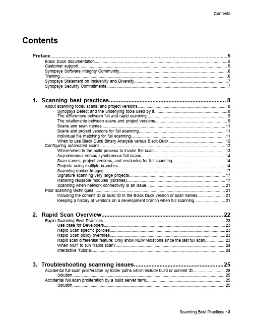
3. Troubleshooting scanning issues........................................................25
Accidental full scan proliferation by folder paths which include build or commit ID............................ 25 Solution......................................................................................................................................25
Contents
Contents
Preface....................................................................................................5
1. Scanning best practices......................................................................... 8