URY2C102MRD中文资料
DA221中文资料

DA221中文资料Diodes1/4Switching diodeDA221M / DA221 / DA204U / DA204K DA228U / DA228K /UMR12Nz Applications Bias circuitsProtection circuitsz Features1) Three types of packages are available. (VMD3, EMD3, UMD3, SMD3)2) Two diode elements are connected in series (V F × 2) per circuit.z ConstructionSilicon epitaxial planarz Circuitz External dimensions (Unit : mm)Diodes2/4z MarkingUMD3DA204UDA228U UMD6UMR12NR12SMD3DA204KDA228KK BUKBU EMD3DA221KVMD3DA221Mz Absolute maximum ratings (T a=25°C)Type V RM (V)V R (V)I FM (mA)I O (mA)I surge (mA)(1μs)(TOTAL)Pd(mW)Tj(°C)Tstg(°C)DA2212020200100300150150?55 to +150DA221M 2020200100300150150?55 to +150DA204U 2020200100300200150?55 to +150DA228K 8080200100300200150?55 to +150UMR12N808020010030020015055 to +15055 to +150DA228U 8080200100300200150?55 to +150DA204K 2020200100300200150Peak reverse voltage Peak forward current Mean rectifying current Surge current Power dissipation Junction temperatureStoragetemperature DC reverse voltagez Electrical characteristics (T a=25°C)TypeForward voltageV F (V)Max.I R (μA)Max.Reverse current Fig.Cond.Cond.I F (mA)V R (V)DA221 1.0100.115 1 to 4DA221M 1.0100.115 1 to 45 to 9UMR12N1.210080DA204U 1.0100.115 1 to 40.1DA228U 1.210080 5 to 90.11.01015DA204K 1 to 40.1DA228K 1.210080 5 to 9Diodes3/4z Electrical characteristic curves (T a=25°C) (DA221, DA204U, DA204K) …Fig.1 to 4T a =125°CD1D1+D20.40.8 1.2 1.6 2.0 2.41001011.00.0175°C5°C25°C125°C75°C25°C25°CF O R W A R D C U R R E N T : I F (m A )FORWARD VOLTAGE : V F (V)Fig.1 Forward characteristicsF O R W A R D C U R R E N T : I F (m A )FORWARD VOLTAGE : V F (V)Fig.2 Forward characteristicsD2 125°CD1 100°C D2 100°CD1 75°C D2 75°C51015200.010.1110100D1 Ta=125°CR E V E R S E CU R R E N T : I R (n A )REVERSE VOLTAGE : V R (V)Fig.3 Reverse characteristics12510C A P A C I T A N C E B E T W E E N T E R M I N A L S : C T (p F )REVERSE VOLTAGE : V R (V)Fig.4 Capacitance between terminals characteristicsDiodes4/4(DA228U, DA228K, UMR12N) …Fig.5 to 9F O R W A R D C U R R E N T : I F (m A )FORWARD VOLTAGE : V F (V)Fig.5 Forward characteristics F O R W A R D C U R R E N T : I F(m A )FORWARD VOLTAGE : V F (V)Fig.6 Forward characteristics R E V E R S E C U R R EN T : I R (n A )REVERSE VOLTAGE : V R (V)Fig.7 Reverse characteristicsR E V E R S E C U R RE N T : I R (n A )REVERSE VOLTAGE : V R (V)Fig.8 Reverse characteristics110C A P A C I T A N C E B E T W E E N T E R M I N A L S : C T (p F )REVERSE VOLTAGE : V R (V)Fig.9 Capacitance between terminals characteristicsAppendixAbout Export Control Order in JapanProducts described herein are the objects of controlled goods in Annex 1 (Item 16) of Export Trade ControlOrder in Japan.In case of export from Japan, please confirm if it applies to "objective" criteria or an "informed" (by MITI clause)on the basis of "catch all controls for Non-Proliferation of Weapons of Mass Destruction.Appendix1-Rev1.0。
CT-MFC.12时钟类型的多功能时间延迟电器说明书

4013614534331 1 piece
85364900
1 piece 89 mm 20 mm 65 mm 0.065 kg 4013614534331
CT-MFC.12
Dimensions
Product Net Width Product Net Height Product Net Depth / Length Product Net Weight
CT-MFC.12 1SVR508020R0000
4013614534331 CT-MFC.12 Time relay, multifunctional 1c/o, 24-48VDC/24-240VAC CT-MFC.12 Time relay, multifunctional 1c/o, 24-48VDC/24-240VAC
Operation -20 ... +60 °C Storage -40 ... +85 °C
Following EU Directive 2011/65/EU
CT-MFC.12
Technical UL/CSA
Maximum Operating Voltage UL/CSA Contact Rating UL/CSA Connecting Capacity UL/CSA
Rigid 1x 20-12 AWG Rigid 2x 20-16 AWG
4.43 ... 7.08 in·lb
CCC_2019010303150608 cULus_20031209-E140448
2CDC111163C0201 1SVD981068
EAC_RU_C-DE.ME77.B.03531 1SVC500020M0001 1SVD981068
2SK1522中文资料(renesas)中文数据手册「EasyDatasheet - 矽搜」

7.如果这些产品或技术受日本出口管理限制,必须是 日本政府根据许可证出口,不能导入比批准目地以外国家.
禁止任何转移或再出口违反出口管制法律和日本及/或目地国家相关规定.
8.请与瑞萨科技公司对这些材料或产品进一步详情 其中所载.
芯片中文手册,看全文,戳
V GS = ±25 V, V DS = 0 V DS = 360 V, V GS = 0 V DS = 400 V, V GS = 0 ID =1毫安,V DS = 10 V ID = 25 A, V GS = 10 V * 1
ID = 25 A, V DS = 10 V * 1 VDS = 10 V, V GS = 0, F = 1兆赫
芯片中文手册,看全文,戳
2SK1521, 2SK1522
绝对最大额定值
(Ta = 25°C)
项目
漏极至源极电压
2SK1521
2SK1522
门源电压
漏极电流
漏电流峰值
身体流失二极管反向漏电流
频道耗散
通道温度
储存温度
注:1.PW
10 µs, 占空比
1%
2.价值在T C = 25°C
符号
ID = 25 A, V GS = 10 V, RL = 1.2
IF = 50 A, V GS = 0
IF = 50 A, V GS = 0, di F/ DT = 100 A /μs的
3
—
远期转移导纳
|yfs|
22
输入电容
Ciss —
输出电容
Coss —
反向传输电容
Crss —
导通延迟时间 上升时间 关断延迟时间 下降时间 身体向前漏二极管 电压
REF02C官方资料

+5V Precision VOLTAGE REFERENCEFEATURESq OUTPUT VOLTAGE: +5V ±0.2% maxq EXCELLENT TEMPERATURE STABILITY: 10ppm/°C max (–40°C to +85°C)q LOW NOISE: 10µV PP max (0.1Hz to 10Hz) q EXCELLENT LINE REGULATION:0.01%/V maxq EXCELLENT LOAD REGULATION:0.008%/mA maxq LOW SUPPLY CURRENT: 1.4mA maxq SHORT-CIRCUIT PROTECTEDq WIDE SUPPLY RANGE: 8V to 40Vq INDUSTRIAL TEMPERATURE RANGE:–40°C to +85°Cq PACKAGE OPTIONS: DIP-8, SO-8APPLICATIONSq PRECISION REGULATORSq CONSTANT CURRENT SOURCE/SINKq DIGITAL VOLTMETERSq V/F CONVERTERSq A/D AND D/A CONVERTERSq PRECISION CALIBRATION STANDARDq TEST EQUIPMENT DESCRIPTIONThe REF02 is a precision 5V voltage reference. The drift is laser trimmed to 10ppm/°C max over the extended industrial and military temperature range. The REF02 provides a stable 5V output that can be externally adjusted over a ±6% range with minimal effect on temperature stability. The REF02 operates from a single supply with an input range of 8V to 40V with a very low current drain of 1mA, and excellent temperature stability due to an improved design. Excellent line and load regulation, low noise, low power, and low cost make the REF02 the best choice whenever a 5V voltage reference is required. Available package options are DIP-8 and SO-8. The REF02 is an ideal choice for portable instrumentation, temperature transducers, Analog-to-Digital (A/D) and Digital-to-Analog (D/A) converters, and digital voltmeters.+5V Reference with Trimmed OutputR E F02R E F02REF02SBVS003B – JANUARY 1993 – REVISED JANUARY 2005Please be aware that an important notice concerning availability, standard warranty, and use in critical applications of Texas Instruments semiconductor products and disclaimers thereto appears at the end of this data sheet.All trademarks are the property of their respective owners.SPECIFICATIONSELECTRICALAt T A = +25°C and V IN = +15V power supply, unless otherwise noted.REF02A REF02BPARAMETER CONDITIONS MIN TYP MAX MIN TYP MAX UNITS OUTPUT VOLTAGE I LOAD = 0mA 4.985 5.0 5.015 4.990✻ 5.010V Change with Temperature(1, 2) (∆V OT)–40°C to +85°C0.050.190.050.13% OUTPUT VOLTAGE DRIFT(3)–40°C to +85°C (TCV O)415410±ppm/°C LONG-TERM STABILITY2000h TestFirst 1000h100100±ppm Second 1000h5050±ppm OUTPUT ADJUSTMENTRANGE R POT = 10kΩ(6)±3±6✻✻% CHANGE IN V O TEMPCOEFFICIENT WITHOUTPUT ADJUSTMENT(–55°C to +125°C)R POT = 10kΩ0.7✻ppm/% OUTPUT VOLTAGE NOISE0.1Hz to 10Hz(5)410✻✻µV PP LINE REGULATION(4)V IN = 8V to 33V0.0060.010✻✻%/V–40°C to +85°C V IN = 8.5V to 33V0.0080.012✻✻LOAD REGULATION(4)I L = 0mA to +10mA0.0050.010✻0.008%/mA–40°C to +85°C I L = 0mA to +10mA0.0070.012✻0.010TURN-ON SETTLING TIME To ±0.1%5✻µsof Final ValueQUIESCENT CURRENT No Load 1.0 1.4✻✻mA LOAD CURRENT (SOURCE)1021✻✻mA LOAD CURRENT (SINK)–0.3–0.5✻✻mA SHORT-CIRCUIT CURRENT V OUT = 030✻mA POWER DISSIPATION No Load1521✻✻mW TEMPERATURE VOLTAGEOUTPUT(7)630✻mV TEMPERATURE COEFFICIENTof Temperature Pin Voltage–55°C to +125°C 2.1mV/°C TEMPERATURE RANGESpecificationREF02A, B, C–40+85✻✻°C NOTES: (1) ∆V OT is defined as the absolute difference between the maximum output and the minimum output voltage over the specified temperature range expressedas a percentage of 5V:∆V V VVOMAX MIN=−×5100(2) ∆V OT specification applies trimmed to +5.000V or untrimmed.(3) TCV O is defined as ∆V OT divided by the temperature range.(4) Line and load regulation specifications include the effect of self heating.(5) Sample tested.(6) 10kΩ potentiometer connected between V OUT and ground with wiper connected to Trim pin. See figure on page 1.(7) Pin 3 is insensitive to capacitive loading. The temperature voltage will be modified by 7mV for each µA of loading.Input Voltage .....................................................................................+40V Operating TemperatureP, U................................................................................–40°C to +85°C Storage Temperature RangeP, U................................................................................–65°C to +125°Output Short Circuit Duration (to Ground or V IN )........................Indefinite Junction Temperature.......................................................–65°C to +150°θJA P .........................................................................................120°C/WU ...........................................................................................80°C/W Lead Temperature (soldering, 60s)...............................................+300°CABSOLUTE MAXIMUM RATINGSPIN CONFIGURATIONSTop ViewDIP/SONC V IN Temp GNDNC NC V OUT Trim12348765This integrated circuit can be damaged by ESD. Texas Instru-ments recommends that all integrated circuits be handled with appropriate precautions. Failure to observe proper handling and installation procedures can cause damage.ESD damage can range from subtle performance degradation to complete device failure. Precision integrated circuits may be more susceptible to damage because very small parametric changes could cause the device not to meet its published specifications.PACKAGE/ORDERING INFORMATION (1)PACKAGE SPECIFICATION MAX DRIFT DRAWING TEMPERATUREPRODUCT V OUT at 25°C (ppm/°C)PACKAGE DESIGNATORRANGE REF02AU 5V ±15mV ±15SO-8D –40°C to +85°C REF02BU 5V ±10mV ±10SO-8D –40°C to +85°C REF02AP 5V ±15mV ±15DIP-8P –40°C to +85°C REF02BP5V ±10mV±10DIP-8P–40°C to +85°CNOTE: (1) For the most current package and ordering information, see the Package Option Addendum located at the end of this data sheet, or see the TI website at .TYPICAL PERFORMANCE CURVESAT T A = +25°C, unless otherwise noted.OUTPUT WIDEBAND NOISEvs BANDWIDTH (0.1Hz to frequency indicated)Frequency (Hz)O u t p u t N o i s e (µV P P )101001k10k100k1M1k100101OUTPUT CHANGE DUE TO THERMAL SHOCKTime (s)P e r c e n t C h a n g e i n O u t p u t V o l t a g e (%)0.0350.030.0250.020.0150.010.0050–10102030405060MAXIMUM LOAD CURRENT vs INPUT VOLTAGEM a x i m u m L o a d C u r r e n t (m A )Input Voltage (V)35302520151050LINE REGULATION vs SUPPLY VOLTAGEInput Voltage (V)654321L i n e R e g u l a t i o n (%/V )66.577.588.599.510LINE REGULATION vs SUPPLY VOLTAGEInput Voltage (V)0.030.0250.020.0150.010.005L i n e R e g u l a t i o n (%/V )51015202530LINE REGULATION vs FREQUENCYL i n e R e g u l a t i o n (d B )Frequency (Hz)101001k10k100k1ML i n e R e g u l at i o n (%/V )96867666564636261660.00030.0010.0030.010.0310.10.311.03.110.0TYPICAL PERFORMANCE CURVES (Cont.)At T A = +25°C, unless otherwise noted.NORMALIZED LOAD REGULATION (∆IL = 10mA)vs TEMPERATURE–601.61.51.41.31.21.11.00.90.80.70.6Temperature (°C)–40–2020406080100120140L o a d R e g (T ) / L o a d R e g (25°C)NORMALIZED LINE REGULATION vs TEMPERATURE–601.41.31.21.11.00.90.80.70.60.50.4Temperature (°C)–40–2020406080100120140L i n e R e g (T ) / L i n e R e g (25°C)REF02 V OUTTemperatureV o l t5.0025.00155.0015.000554.99954.9994.99854.9984.9975–60–40–2020406080100120140MAXIMUM LOAD CURRENT vs TEMPERATURETemperature (°C)302520151050M a x i m u m L o a d C u r r e n t (m A )–60–40–20020406080100120140QUIESCENT CURRENT vs TEMPERATURETemperature (°C)1.11.081.061.041.021.00.98Q u i e s c e n t C u r r e n t (m A )–60–40–2020406080100120140TYPICAL TEMPERATURE VOLTAGE OUTPUTvs TEMPERATURET e m p e r a t u r e V o l t a g e O u t p u t (m V )Temperature (°C)–60–40–20020406080100120140830780730680630580530480430TYPICAL PERFORMANCE CURVES (Cont.)At T A = +25°C, unless otherwise noted.LONG-TERM STABILITY (1st 1000h)Hours244872961681922403364085045766967448649121008p p m200150100500–50–100–150–200–250LONG-TERM STABILITY (2nd 1000h)Hours100810801176127213441440153616081680177618481944p p m200150100500–50–100–150–200–25019441008504LONG TERM STABILITY (2000h)Hoursp p m3002001000–100–200–300OUTPUT ADJUSTMENTThe REF02 trim terminal can be used to adjust the voltage over a 5V ±150mV range. This feature allows the system designer to trim system errors by setting the reference to a voltage other than 5V, including 5.12V (1) for binary applica-tions (see circuit on page 1).Adjustment of the output does not significantly affect the temperature performance of the device. The temperature coefficient change is approximately 0.7ppm/°C for 100mV of output adjustment.NOTE: (1) 20mV LSB for 8-bit applications.TYPICAL APPLICATIONSFIGURE 2. ±5V Precision Reference.FIGURE 1. Burn-In Circuit.REFERENCE STACKINGPROVIDES OUTSTANDING LINE REGULATION By stacking two REF01s and one REF02, a systems designer can achieve 5V, 15V, and 25V outputs. One very important advantage of this circuit is the near-perfect line regulation at 5V and 15V outputs. This circuit can accept a 27V to 55V change to the input with less than the noise voltage as a change to the output voltage. R B , a load bypass resistor,supplies current I SY for the 15V regulator.Any number of REF01s and REF02s can be stacked in this configuration. For example, if ten devices are stacked in this configuration, ten 5V or five 10V outputs are achieved. The line voltage may range from 100V to 130V. Care should be exercised to insure that the total load currents do not exceed the maximum usable current, which is typically 21mA.PACKAGING INFORMATIONOrderable Device Status(1)PackageType PackageDrawingPins PackageQtyEco Plan(2)Lead/Ball Finish MSL Peak Temp(3)REF02AP ACTIVE PDIP P850Green(RoHS&no Sb/Br)CU NIPDAU N/A for Pkg TypeREF02APG4ACTIVE PDIP P850Green(RoHS&no Sb/Br)CU NIPDAU N/A for Pkg TypeREF02AU ACTIVE SOIC D8100Green(RoHS&no Sb/Br)CU NIPDAU Level-3-260C-168HRREF02AU/2K5ACTIVE SOIC D82500Pb-Free(RoHS)CU NIPDAU Level-3-260C-168HRREF02AU/2K5E4ACTIVE SOIC D82500Green(RoHS&no Sb/Br)CU NIPDAU Level-3-260C-168HRREF02AUE4ACTIVE SOIC D8100Green(RoHS&no Sb/Br)CU NIPDAU Level-3-260C-168HRREF02AUG4ACTIVE SOIC D8100Green(RoHS&no Sb/Br)CU NIPDAU Level-3-260C-168HRREF02BP ACTIVE PDIP P850Green(RoHS&no Sb/Br)CU NIPDAU N/A for Pkg TypeREF02BPG4ACTIVE PDIP P850Green(RoHS&no Sb/Br)CU NIPDAU N/A for Pkg TypeREF02BU ACTIVE SOIC D8100Green(RoHS&no Sb/Br)CU NIPDAU Level-3-260C-168HRREF02BU/2K5ACTIVE SOIC D82500Pb-Free(RoHS)CU NIPDAU Level-3-260C-168HRREF02BU/2K5E4ACTIVE SOIC D82500Pb-Free(RoHS)CU NIPDAU Level-3-260C-168HRREF02BUE4ACTIVE SOIC D8100Pb-Free(RoHS)CU NIPDAU Level-3-260C-168HRREF02BUG4ACTIVE SOIC D8100Green(RoHS&no Sb/Br)CU NIPDAU Level-3-260C-168HR(1)The marketing status values are defined as follows:ACTIVE:Product device recommended for new designs.LIFEBUY:TI has announced that the device will be discontinued,and a lifetime-buy period is in effect.NRND:Not recommended for new designs.Device is in production to support existing customers,but TI does not recommend using this part in a new design.PREVIEW:Device has been announced but is not in production.Samples may or may not be available.OBSOLETE:TI has discontinued the production of the device.(2)Eco Plan-The planned eco-friendly classification:Pb-Free(RoHS),Pb-Free(RoHS Exempt),or Green(RoHS&no Sb/Br)-please check /productcontent for the latest availability information and additional product content details.TBD:The Pb-Free/Green conversion plan has not been defined.Pb-Free(RoHS):TI's terms"Lead-Free"or"Pb-Free"mean semiconductor products that are compatible with the current RoHS requirements for all6substances,including the requirement that lead not exceed0.1%by weight in homogeneous materials.Where designed to be soldered at high temperatures,TI Pb-Free products are suitable for use in specified lead-free processes.Pb-Free(RoHS Exempt):This component has a RoHS exemption for either1)lead-based flip-chip solder bumps used between the die and package,or2)lead-based die adhesive used between the die and leadframe.The component is otherwise considered Pb-Free(RoHS compatible)as defined above.Green(RoHS&no Sb/Br):TI defines"Green"to mean Pb-Free(RoHS compatible),and free of Bromine(Br)and Antimony(Sb)based flame retardants(Br or Sb do not exceed0.1%by weight in homogeneous material)(3)MSL,Peak Temp.--The Moisture Sensitivity Level rating according to the JEDEC industry standard classifications,and peak solder temperature.Important Information and Disclaimer:The information provided on this page represents TI's knowledge and belief as of the date that it isprovided.TI bases its knowledge and belief on information provided by third parties,and makes no representation or warranty as to the accuracy of such information.Efforts are underway to better integrate information from third parties.TI has taken and continues to take reasonable steps to provide representative and accurate information but may not have conducted destructive testing or chemical analysis on incoming materials and chemicals.TI and TI suppliers consider certain information to be proprietary,and thus CAS numbers and other limited information may not be available for release.In no event shall TI's liability arising out of such information exceed the total purchase price of the TI part(s)at issue in this document sold by TI to Customer on an annual basis.IMPORTANT NOTICETexas Instruments Incorporated and its subsidiaries (TI) reserve the right to make corrections, modifications, enhancements, improvements, and other changes to its products and services at any time and todiscontinue any product or service without notice. Customers should obtain the latest relevant informationbefore placing orders and should verify that such information is current and complete. All products are soldsubject to TI’s terms and conditions of sale supplied at the time of order acknowledgment.TI warrants performance of its hardware products to the specifications applicable at the time of sale inaccordance with TI’s standard warranty. Testing and other quality control techniques are used to the extentTI deems necessary to support this warranty. Except where mandated by government requirements, testingof all parameters of each product is not necessarily performed.TI assumes no liability for applications assistance or customer product design. Customers are responsiblefor their products and applications using TI components. To minimize the risks associated with customerproducts and applications, customers should provide adequate design and operating safeguards.TI does not warrant or represent that any license, either express or implied, is granted under any TI patentright, copyright, mask work right, or other TI intellectual property right relating to any combination, machine,or process in which TI products or services are used. Information published by TI regarding third-partyproducts or services does not constitute a license from TI to use such products or services or a warranty orendorsement thereof. Use of such information may require a license from a third party under the patents orother intellectual property of the third party, or a license from TI under the patents or other intellectualproperty of TI.Reproduction of information in TI data books or data sheets is permissible only if reproduction is withoutalteration and is accompanied by all associated warranties, conditions, limitations, and notices.Reproduction of this information with alteration is an unfair and deceptive business practice. TI is notresponsible or liable for such altered documentation.Resale of TI products or services with statements different from or beyond the parameters stated by TI forthat product or service voids all express and any implied warranties for the associated TI product or serviceand is an unfair and deceptive business practice. TI is not responsible or liable for any such statements.Following are URLs where you can obtain information on other Texas Instruments products and applicationsolutions:Products ApplicationsAmplifiers Audio /audioData Converters Automotive /automotive/broadbandBroadbandDSP DigitalControl /digitalcontrol Interface Military /military Logic Power Mgmt Optical Networking /opticalnetworkSecurity /security Microcontrollers Low Power Wireless /lpw Telephony /telephonyVideo & Imaging /video/wirelessWirelessMailing Address: Texas InstrumentsPost Office Box 655303 Dallas, Texas 75265Copyright © 2007, Texas Instruments Incorporated。
贴片元件标记对应型号资料
贴片元件标记对应型号资料贴片元件标记对应型号资料标记型号生产厂家封装引脚数1HR 2SD2185 松下MiniP3-F1 3 1HS 2SD2185 松下MiniP3-F1 3 1IR 2SB1440 松下MiniP3-F1 3 1IS 2SB1440 松下MiniP3-F1 3 1KQ 2SD2210 松下MiniP3-F1 3 1KR 2SD2210 松下MiniP3-F1 3 1KS 2SD2210 松下MiniP3-F1 3 1S 2SD2413 松下MiniP3-F1 3 1U 2SB1589 松下MiniP3-F1 3 1V 2SD2441 松下MiniP3-F1 3 1XQ 2SB1599 松下MiniP3-F1 3 1XR 2SB1599 松下MiniP3-F1 3 1YQ 2SD2457 松下MiniP3-F1 3 1YR 2SD2457 松下MiniP3-F1 3 2A 2SC5712 東芝SC-63 32AR 2SC5026 松下MiniP3-F1 3 2AS 2SC5026 松下MiniP3-F1 3 2C 2SC5713 東芝SC-63 32E 2SC5714 東芝SC-63 32ER 2SD2459 松下MiniP3-F1 3 2ES 2SD2459 松下MiniP3-F1 3 3D 2SC5819 東芝SC-63 33E 2SC5785 東芝SC-63 34D 2SA2069 東芝SC-63 34E 2SA2066 東芝SC-63 34F 2SA2059 東芝SC-63 34G 2SC2060 東芝SC-63 37O 2SA1621 東芝SC-59 37Y 2SA1621 東芝SC-59 3A 2SC2413K ROHM SC-59A 3 A 2SC4098 ROHM 3A1 1SS272 東芝SC-61 4A3 1SS181 東芝SC-59 3A3 1SS300 東芝SC-70 3A4 1SS319 東芝SC-61 4A4 1SS383 東芝4A5 1SS384 東芝SOT-343 4A5 1SS391 東芝SC-61 4A6 HN2S01F 東芝SC-74 6A6 HN2S01FU 東芝SC-88 6 A7 1SS402 東芝SOT-343 4A9 1SS294 東芝SC-59 3AL 2SA1971 東芝SC-63 3AL 2SC5307 東芝SC-63 3AN 2SC2532 東芝SC-59 3 AO 2SA2880 東芝SC-63 3 AQ 2SB766 松下MiniP3-F1 3 AR 2SB766 松下MiniP3-F1 3 AS 2SB766 松下MiniP3-F1 3 AU 2SB804 NEC SC-62 3AV 2SB804 NEC SC-62 3AW 2SB804 NEC SC-62 3AY 2SA2880 東芝SC-63 3B 2CS4081 ROHM 3B 2SC2412K ROHM SC-59A 3 B3 1SS184 東芝SC-59 3B3 1SS301 東芝SC-70 3B9 1SS311 東芝SC-59 3B9 1SS397 東芝SC-70 3BD 1SS271 東芝SC-59 3BE 1SV172 東芝BF 1SS268 東芝SC-59 3BG 1SS269 東芝SC-59 3BH 1SS295 東芝SC-59 3BO 2SA1200 東芝SC-63 3 BQ 2SB766A 松下MiniP3-F1 3 BR 2SB766A 松下MiniP3-F1 3 BS 2SB766A 松下MiniP3-F1 3 BU 2SD1005 NEC SC-62 3BU DA228K ROHM SC-59 3 BU DA228U ROHM SC-70 3 BV 2SD1005 NEC SC-62 3BW 2SD1005 NEC SC-62 3BY 2SA1200 東芝SC-63 3C 2SC2411K ROHM SC-59A 3C 2SC4097 ROHM 3C1 1SS352 東芝C1 1SS387 東芝C3 1SS226 東芝SC-59 3C9 1SS307 東芝SC-59 3CEO 2SC3325 東芝SC-59 3 CEY 2SC3325 東芝SC-59 3CG 2SA1163 東芝SC-59 3CK 2SD999 NEC SC-62 3CL 2SD999 NEC SC-62 3CM 2SD999 NEC SC-62 3CO 2SC2881 東芝SC-63 3CO 2SC4209 東芝SC-59 3CQ 2SB767 松下MiniP3-F1 3 CR 2SB767 松下MiniP3-F1 3 CY 2SC2881 東芝SC-63 3CY 2SC4209 東芝SC-59 3D 2SA1037KLN ROHM SC-59A 3 D3 1SS187 東芝SC-59 3DG 2SC2713 東芝SC-59 3DK 2SB798 NEC SC-62 3DL 2SB798 NEC SC-62 3DM 2SB798 NEC SC-62 3DO 2SA1201 東芝SC-63 3DQ 2SB789 松下MiniP3-F1 3 DR 2SB789 松下MiniP3-F1 3 DY 2SA1201 東芝SC-63 3E3 1SS190 東芝SC-59 3EK 2SD1001 NEC SC-62 3EL 2SD1001 NEC SC-62 3EM 2SD1001 NEC SC-62 3EO 2SC2882 東芝SC-63 3EQ 2SB789A 松下MiniP3-F1 3 ER 2SB789A 松下MiniP3-F1 3 EX 2SD2402 NEC SC-62 3EY 2SC2882 東芝SC-63 3EY 2SD2402 NEC SC-62 3EZ 2SD2402 NEC SC-62 3F 2SA1037K ROHM SC-59A 3 F 2SA1576 ROHM 3F3 1SS193 東芝SC-59 3F5 1SS250 東芝SC-59 3F5 1SS370 東芝SC-70 3F5 1SS403 東芝SOD-323 2F9 1SS321 東芝SC-59 3FK 2SB800 NEC SC-62 3FL 2SB800 NEC SC-62 3FM 2SB800 NEC SC-62 3FO 2SA1202 東芝SC-63 3FX 2SB1571 NEC SC-62 3FY 2SA1202 東芝SC-63 3FY 2SB1571 NEC SC-62 3FZ 2SB1571 NEC SC-62 3G3 1SS196 東芝SC-59 3G3 2SA1455K ROHM SC-59A 3 GK 2SD1615 NEC SC-62 3GL 2SD1615 NEC SC-62 3GM 2SD1615 NEC SC-62 3 GO 2SC2883 東芝SC-63 3 GP 2SD1615A NEC SC-62 3 GQ 2SD1615A NEC SC-62 3 GX 2SD2403 NEC SC-62 3GY 2SC2883 東芝SC-63 3GY 2SD2403 NEC SC-62 3GZ 2SD2403 NEC SC-62 3H9 1SS344 東芝SC-59 3HK 2SD1006 NEC SC-62 3HL 2SD1006 NEC SC-62 3HM 2SD1006 NEC SC-62 3 HO 2SA1203 東芝SC-63 3HP 2SD1007 NEC SC-62 3HQ 2SD1007 NEC SC-62 3HR 2SD1007 NEC SC-62 3HR 2SB956 松下MiniP3-F1 3 HS 2SB956 松下MiniP3-F1 3 HX 2SB1572 NEC SC-62 3HY 2SA1203 東芝SC-63 3HY 2SB1572 NEC SC-62 3HZ 2SB1572 NEC SC-62 3I9 1SS336 東芝SC-59 3IK 2SA1463 NEC SC-62 3IL 2SA1463 NEC SC-62 3IO 2SC3515 東芝SC-63 3IQ 2SB1073 松下MiniP3-F1 3 IR 2SC3515 東芝SC-63 3IR 2SB1073 松下MiniP3-F1 3 J 2SC2059K ROHM SC-59A 3J 2SC4099 ROHM 3J9 1SS337 東芝SC-59 3JO 2SA1384 東芝SC-63 3JR 2SK208 東芝SC-59 3JR 2SA1384 東芝SC-63 3K DA221 ROHM SC-75A 3K DA204U ROHM SC-70 3K DA204K ROHM SC-59 3K9 1SS348 東芝SC-59 3KA 2SC4409 東芝SC-63 3KD 2SC4541 東芝SC-63 3KK 2SB805 NEC SC-62 3KL 2SB805 NEC SC-62 3KM 2SB805 NEC SC-62 3KP 2SB806 NEC SC-62 3KQ 2SB806 NEC SC-62 3KR 2SB806 NEC SC-62 3L 2SC2412KLN ROHM SC-59A 3 L9 1SS349 東芝SC-59 3LA 2SA1681 東芝SC-63 3LD 2SA1736 東芝SC-63 3LK 2SD1000 NEC SC-62 3LL 2SD1000 NEC SC-62 3LM 2SD1000 NEC SC-62 3MK 2SB799 NEC SC-62 3 ML 2SB799 NEC SC-62 3 MM 2SB799 NEC SC-62 3 MO 2SC2873 東芝SC-63 3 MY 2SC2873 東芝SC-63 3 N9 1SS372 東芝SC-70 3 N9 1SS374 東芝SC-59 3 NA 2SK1273 NEC SC-62 3 NB 2SK1586 NEC SC-62 3 NC 2SK1485 NEC SC-62 3 ND 2SK1583 NEC SC-62 3 NE 2SK1585 NEC SC-62 3 NF 2SK1587 NEC SC-62 3 NG 2SK1588 NEC SC-62 3 NH 2SK1584 NEC SC-62 3 NI 2SK1586 NEC SC-62 3 NJ 2SK2111 NEC SC-62 3 NK 2SC2780 NEC SC-62 3 NL 2SC2780 NEC SC-62 3 NM 2SC2780 NEC SC-62 3 NO 2SA1213 東芝SC-63 3 NO 2SK1592 NEC SC-62 3 NP 2SK1593 NEC SC-62 3 NQ 2SK1959 NEC SC-62 3 NR 2SK1960 NEC SC-62 3 NS 2SK2109 NEC SC-62 3 NT 2SK2110 NEC SC-62 3 NV 2SK2112 NEC SC-62 3 NW 2SK2159 NEC SC-62 3 NX 2SK2857 NEC SC-62 3 NY 2SA1213 東芝SC-63 3 O9 1SS377 東芝SC-59 3 O9 1SS378 東芝SC-70 3 O9 1SS385 東芝SC-75 3 O9 1SS385F 東芝SC-81 3 OK 2SC3736 NEC SC-62 3 OL 2SC3736 NEC SC-62 3PA 2SJ179 NEC SC-62 3PB 2SJ197 NEC SC-62 3PC 2SJ199 NEC SC-62 3PD 2SJ205 NEC SC-62 3PE 2SJ207 NEC SC-62 3PF 2SJ208 NEC SC-62 3PH 2SJ206 NEC SC-62 3PO 2SC2884 東芝SC-63 3 PO 2SJ212 NEC SC-62 3PP 2SJ213 NEC SC-62 3PQ 2SJ355 NEC SC-62 3PR 2SJ356 NEC SC-62 3PY 2SC2884 東芝SC-63 3 QO 2SC2714 東芝3R12 UMR12N ROHM SC-88 6 R23 2SC3356 Q NEC SC-59 3 R24 2SC3356 R NEC SC-59 3 R25 2SC3356 S NEC SC-59 3 R9 1SS392 東芝SC-59 3R9 1SS393 東芝SC-70 3RQ 2SD1280 松下MiniP3-F1 3 RR 2SD1280 松下MiniP3-F1 3 RS 2SD1280 松下MiniP3-F1 3 S2 1SS315 東芝SC-59 3S9 1SS394 東芝SC-59 3SA 2SC2982 東芝SC-63 3SK 2SC3554 NEC SC-62 3SL 2SC3554 NEC SC-62 3SM 2SC3554 NEC SC-62 3 SO 2SA1162 東芝SC-59 3T9 1SS396 東芝SC-59 3TA 2SA1314 東芝SC-63 3TA 1SV231 東芝1-1E1A 2TB 2SA1314 東芝SC-63 3TC 2SA1314 東芝SC-63 3TE 2SD1702 NEC SC-62 3TF 2SD1702 NEC SC-62 3TL 2SC3617 NEC SC-62 3TM 2SC3617 NEC SC-62 3TQ 2SD1699 NEC SC-62 3TQ 2SD1119 松下MiniP3-F1 3 TR 2SD1699 NEC SC-62 3TR 2SD1119 松下MiniP3-F1 3 UK 2SC3618 NEC SC-62 3UL 2SC3618 NEC SC-62 3UM 2SC3618 NEC SC-62 3VK 2SD1950 NEC SC-62 3VL 2SD1950 NEC SC-62 3VM 2SD1950 NEC SC-62 3 VR 2SD968A 松下MiniP3-F1 3 VS 2SD968A 松下MiniP3-F1 3 VY 2SJ106 東芝SC-59 3W 2SD1383K ROHM SC-59A 3 W3 FMW3 ROHM 5X9 1SS398 東芝SC-59 3XK 2SD1614 NEC SC-62 3XL 2SD1614 NEC SC-62 3XM 2SD1614 NEC SC-62 3 XN 2SD1784 東芝SC-63 3 XR 2SD875 松下MiniP3-F1 3 XS 2SD875 松下MiniP3-F1 3 YB 2SK680A NEC SC-62 3YK 2SB1115 NEC SC-62 3YL 2SB1115 NEC SC-62 3YM 2SB1115 NEC SC-62 3YP 2SB1115A NEC SC-62 3 YQ 2SB1115A NEC SC-62 3 YQ 2SD874A 松下MiniP3-F1 3 YR 2SD874A 松下MiniP3-F1 3 YS 2SD874A 松下MiniP3-F1 3 Z7 2SK2549 東芝SC-63 3Z8 2SJ360 東芝SC-63 3Z9 2SJ465 東芝SC-63 3ZA 2SK2615 東芝SC-63 3ZB 2SK2963 東芝SC-63 3 ZC 2SK2964 東芝SC-63 3 ZD 2SK2992 東芝SC-63 3 ZE 2SJ508 東芝SC-63 3ZF 2SJ511 東芝SC-63 3ZG 2SK3471 東芝SC-63 3 ZK 2SB1114 NEC SC-62 3 ZL 2SB1114 NEC SC-62 3 ZM 2SB1114 NEC SC-62 3 ZO 2SA1182 東芝SC-59 3 ZQ 2SD874 松下MiniP3-F1 3 ZR 2SD874 松下MiniP3-F1 3 ZS 2SD874 松下MiniP3-F1 3 ZX 2SB1628 NEC SC-62 3 ZY 2SB1628 NEC SC-62 3 ZZ 2SB1628 NEC SC-62 3。
KIRAY 200红外测温仪说明书

Distance from the targetInfrared thermometer150300900mm Supplied with thermocouple K probeTrigger (ENT)DescriptionSet technical unit (°C/°F)1 – Up button. It allows to increment emissivity and the thresholds of high and low alarm and to move to the next recorded value.2 – Set button. It allows to activate or deactivate laser and backlight of the screen. It also allows to record a temperature.3 – Mode button. It allows to navigate through the modes (emissivity, max. value, min. value,difference, average, high alarm, low alarm, TK value and recorded values). 4 – Down button. It allows to decrement emissivity and the thresholds of high and low alarm and to move to the previous recorded value.KIRAY 200 buttons1 - Continuous measurement indicator2 - Unit of measurement (°C / °F)3 - Low battery indicator4 - Low alarm indicator5 - Temperature value : MAX, MIN, DIF (difference between MAX and MIN values), AVG (average), HAL (high alarm), LAL (low alarm),TK (K thermocouple probe temperature)and LOG (recorded value)6 - High alarm indicator7 - EMS, MAX, MIN, DIF, AVG, HAL, LAL, TK and LOG indicator 8 - Temperature value9 - Current measurement indicator10 - HOLD indicator (fixed measurement)11 - Emissivity value12 - Laser in operation indicatorDisplayLaser sighting outputBatterycompartmentLCDbacklighted display Up button Mode buttonDown button1234Backlight and laser button Probe inputSet continuousmeasurement (On/Off)Set alarm (On/Off)Modes flow chartMODEMODE = bouton mode SET = bouton SET ENT = gâchette EMSRég lage de l’émissivité (E MS)avec l es to uche hau t e t bas.Affichag e de la temp éra tur e maximum Affichag e de la temp éra tur e mini mum MODEMODEMODEMODEAffichag e de la temp éra tur e différe ntielle (en tre MIN et MAX)AVGAffichag e de la temp éra tur e moyen ne ca lculée pen dan t u ne pr ise de mesure MODEHALAffichag e et réglag e d e l’a larme de te mpér ature haute Affichag e et réglag e d e l’a larme de te mpér ature basse MODELALAffichag e de la temp éra tur e pa r la so nde th ermo co uple K do nnée MODETKMODELOGAffichag e et en reg istre ment de s température s avec le bouton SETDIFMAXMINMODE0.9535.217.317.920.303001523.523.51Set emissivity (EMS) with up and down buttons Display of maximum temperatureDisplay of minimum temperatureDisplay of the difference of temperature between max. and min. temperaturesDisplay of average temperature calculated over a measurement periodDisplay and set of the alarm of high temperatureDisplay and set of the alarm of low temperatureDisplay of the temperature given by the K thermocouple probeDisplay and recording of temperatures with SET button MODE = mode button SET = set button ENT = triggerMode buttonAllows to define the required measurement : Max, Min, AVG, DIF, etc. ... pressing as many times on this button.- EMS : when KIRAY200 instrument is turned on, press MODE button until EMS appears at the bottom left of the screen. Set emissivity by pressing on UP button to increment it or DOWN button to decrement it. By default, the emissivity is set to 0.95.- MIN ou MAX : select the Min or Max. temperature.During a measurement period, keep ENT pressed : the KIRA Y200 instrument displays the temperature of the area sighted by the laser. Press MODE button until MAX or MIN is displayed at the bottom of the screen. These values relate to the temperatures taken by the instrument and the thermocouple probe.- DIF : during a measurement period, press MODE button until DIF appears at the bottom left of the screen. The displayed valuecorresponds to the difference between MAX value and MIN value. -AVG : during a measurement period, press MODE button until AVG appears at the bottom left of the screen. The displayed value corresponds to the average temperature calculated during a measurement period.- HAL : when KIRA Y200 instrument is turned on, press MODE button until HAL appears at the bottom left of the screen. The displayed value corresponds to the alarm of high temperature . Set this alarm by incrementing it with up button or by decrementing it with down button.- LAL : when KIRA Y200 instrument is turned on, press MODE button until LAL appears at the bottom left of the screen. The displayed value corresponds to the alarm of low temperature . Set this alarm by incrementing it with up button or by decrementing it with down button.- TK : when KIRA Y200 instrument is turned on, press MODE button until TK appears at the bottom left of the screen. The displayed value corresponds to the measured temperature by the K thermocouple probe.- LOG : when KIRA Y200 instrument is turned on, press MODE button until LOG appears at the bottom left of the screen.Next to LOG , a number between 1 and 20 also appears ; itcorresponds to LOG location. If no temperature has been recorded in the shown LOG location, 4 dashes will appear in the lower right corner. To record a temperature, you have to be on LOG mode, then choose an empty LOG location (---- visible) and press SET button during the measurement or when the measurement is fixed (HOLD ).From this mode, you can also clear all the recorded temperatures : press and keep the trigger pressed and press down button at the same time until reaching the zero recording, then press SET button while keeping ENT pressed. A beep is emitted by KIRA Y200instrument and the LOG location moves automatically to 1, signifying that all data have been cleared.Settings before measurementBefore measuring temperature, it is recommended to make some settings:- Set technical unit (°C or °F )- Set the continuous measurement (On or Off )- Set the alarm (On or Off )To set these 3 parameters, open the battery door by pushing on both sides of the trigger. It is not necessary to disconnect the battery to make these settings.●Set technical unit (°C or °F)Set the selector unit to °C or °F with a screwdriver.●Set the continuous measurement This setting allows to let the Kiray200 instrument in measurement. It does not shut off after 7 seconds.Set the selector on On (continuous measurement is active) or on Off(continuous measurement is inactive) with a screwdriver.●Set the alarmThis setting allows to activate or deactivate high and low alarm.Set the selector on On (alarms are active) or on Off (alarms are inactive) with a screwdriver.Operating mode-Press ENT trigger to turn on the instrument. The backlighted screen, indicating the temperature, and the laser turn on.-Keep ENT pressed. Place the laser sighting at the center of the area to be measured.-Release ENT.-Read the displayed temperature. (The display stays on for 7 seconds after the last manipulation).-HOLD appears at the top left of the screen ; measurement stays displayed.-The KIRA Y200 instrument keeps in memory the last function used.Command buttonsENT Trigger- Turning on the device.- ENT pressed : activation of the laser sighting and temperature measurement.- ENT released : display is on HOLD (HOLD fixed), and give the last measurement. Display stays on for 7 seconds. If no buttons are activated and continuous measurement is inactive, the instrument turns off after 7 seconds.MODE LockAlarms must be activated (see paragraph Settings before measurement)UnitTo prevent damage on your instrument or equipment pleasecarefully respect these conditions :• EN 50081-1 : 1992, Electromagnetic compatibility, Part 1• EN 50082-1 : 1992, Electromagnetic compatibility, Part 2This device meets with following standards' requirements.●Case holster with passer-by belt ● User manual ●K thermocouple probeR e f. N T a n g - K I R A Y 200 - 07/09 B - R C S (24) P ér i g u e u x 349 282095N o n -c o n t r a c t u a l d o c u m e n t – W e r e s e r v e t h e r i g h t t o m o d i f y t h e c h a r a c t e r i s t i c s o f o u r p r o d u c t s w i t h o u t p r i o r n o t i c e .CE certificationMaintenanceTo install or change the 9V battery, open the part near the trigger and put it in the battery compartment.AccessoriesImportant informationFor correct measurements :• Do not take any measurement on metal or shiny or reflective surfaces.• Do not measure through transparent surfaces such as glass, for example.• Water vapor, dust, smoke, etc ... may prevent correctmeasurements because they obstruct the optic of the instrument.• Make sure that the target is larger than the size of the laser sighting.To avoid any inconvenience:• Do not aim directly or indirectly (reflection on reflective surfaces) the laser in the eyes.• Change the batteries when the indicator blinks.• Do not use the thermometer around explosive gas, vapor or dust • Do not leave the device with the lock on (lock at the top right of the screen) because in this configuration, the instrument does not turn off automatically.p ro tég er d es ch am p électriq u es et m ag n étiq es et To protect from electric and magnetic fields of static Protect from thermalshockEmissivityEmissivity is a term used to describe the energy-emitting characteristics of materials.Most (90% of typical applications) organic materials and painted or oxidized surfaces have an emissivity of 0.95 (pre-set in the unit). Inaccurate readings will result from measuring shiny or polished metal surfaces. To compensate; cover the surface to be measured with masking tape or flat black paint. Allow time for the tape to reach the same temperature as the material underneath it. Measure the temperature of the tape or painted surface.See table below for values of emissivity of specific materials :Ice 0.98Iron 0.70Lead 0.50Limestone 0.98Oil 0.94Paint 0.93Paper 0.95Plastic 0.95Rubber 0.95Sand 0.90Skin 0.98Snow 0.90Steel 0.80Textile 0.94Wood 0.94Aluminium 0.30Asbestos 0.95Asphalt 0.95Basalt 0.70Brass 0.50Brick 0.90Carbon 0.85Ceramic 0.95Concrete 0.95Copper 0.95Dirt0.94Frozen food 0.90Hot food0.93Glass 0.85Water0.93Once returned to KIMO, required waste collection will be assured in the respect of the environment in accordance to 2002/96/CE guidelines relating to WEEE.。
URY1J222MRD中文资料

Radial Lead Type
Sleeve (P.E.T.)
Type numbering system (Example : 10V 2200µF)
φd
1 2 3 4 5 6 7 8 9 10 11
URY 1 A 2 2 2 MHD
φD+0.5 MAX P ± 0.5
Configuration Capacitance tolerance (±20%) Rated Capacitance (2200µF)
Capacitance change tan δ Leakage current
Within ± 20% of initial value 200% or less of initial specified value Initial specified value or less
Shelf Life Marking
38 47 85
Rated Ripple (mArms) at 105°C 120Hz
Frequency coefficient of rated ripple current
V
Cap.(µF) Frequency
6.3 ~ 100 160 ~ 450
100 ~ 680 1000 ~ 4700 6.8 ~ 100
160 2C
200 2D 12.5 × 12.5 16 × 12.5 18 × 12.5 25 × 12.5 110 170 230 310
250 2E 16 × 12.5 18 × 12.5 22 × 12.5 130 170 190
10 22 33 47 68 100 220 330 470
100 220 330 470 680 101 221 331 471
Voyager Focus 2 UC商品说明书
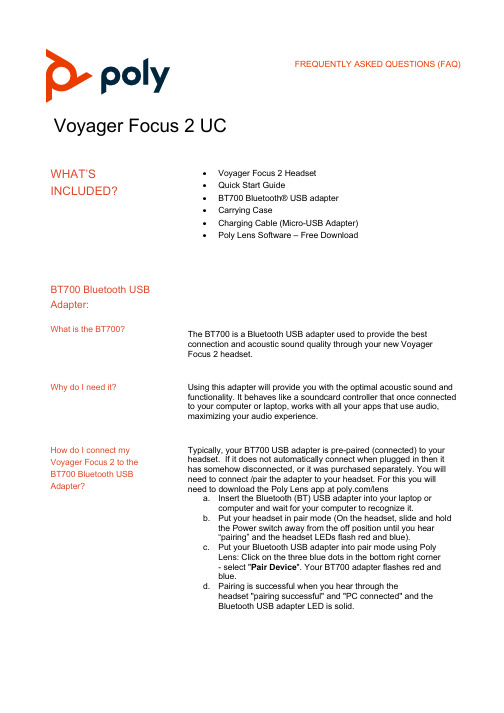
Voyager Focus 2 UCWHAT’S INCLUDED? •Voyager Focus 2 Headset•Quick Start Guide•BT700 Bluetooth® USB adapter •Carrying Case•Charging Cable (Micro-USB Adapter) •Poly Lens Software – Free DownloadBT700 Bluetooth USBAdapter:What is the BT700?The BT700 is a Bluetooth USB adapter used to provide the bestconnection and acoustic sound quality through your new VoyagerFocus 2 headset.Why do I need it? Using this adapter will provide you with the optimal acoustic sound andfunctionality. It behaves like a soundcard controller that once connectedto your computer or laptop, works with all your apps that use audio,maximizing your audio experience.How do I connect my Voyager Focus 2 to the BT700 Bluetooth USB Adapter? Typically, your BT700 USB adapter is pre-paired (connected) to your headset. If it does not automatically connect when plugged in then it has somehow disconnected, or it was purchased separately. You will need to connect /pair the adapter to your headset. For this you will need to download the Poly Lens app at /lensa. Insert the Bluetooth (BT) USB adapter into your laptop orcomputer and wait for your computer to recognize it.b. Put your headset in pair mode (On the headset, slide and holdthe Power switch away from the off position until you hear“pairing” and the headset LEDs flash red and blue).c. Put your Bluetooth USB adapter into pair mode using PolyLens: Click on the three blue dots in the bottom right corner- select "Pair Device". Your BT700 adapter flashes red andblue.d. Pairing is successful when you hear through theheadset "pairing successful" and "PC connected" and theBluetooth USB adapter LED is solid.Am I able to use my BT700 USB Adapter on multiple devices?LEARN MY DEVICE Your BT700 Bluetooth (BT) USB adapter will remember up to 2 devices but will only connect to one at a time. If experiencing trouble, check that your Voyager Focus 2 device is the only one connected, if required turn off the second device.What are the featuresavailable with my newVoyager Focus 2 andmy BT700?Call controls / volume Headset buttons can control call functions. Call control is being able tomute, answer/ end calls, and adjust call volume. On the device youmay also play/ pause, go to the next track or previous, and eveninteract with your MS Teams softphone.ANC Your Voyager Focus 2 includes Poly’s latest Advanced DigitalHybrid Active Noise Cancelling (ANC) which reduces external noiseand enhances your music and sound quality. The ANC switch includes3 settings0. ANC off1. Recommended for office use2. Recommended for loud environmentsNoise cancelling microphone with Acoustic Fence technology Your Voyager Focus 2 headset includes Acoustic Fencetechnology that reduces background noise so that your caller hears you and not the noise around you. For optimum performance ensure that the microphone boom is positioned at the corner of your mouth.Smart microphone boom The microphone boom detects which way the headset is beingworn and automatically maintains the left and right audio. Putting theboom in the upright position will mute the call.Mute Mute your headset by:a. Tapping the mute button while on a callb. Rotating your microphone boom and clicking it into the uppositionc. Taking off the headset and then putting it back on to unmute2Power on On your headset there is a switch. Slide the switch to power on or off.Talk time / Battery life Battery life can be affected by how you use it.a.Talk time: Up to 19 hours with ANC off and up to 16 hours withANC on.b.Listening time: Up to 40 hours with ANC off and up to 24hours with ANC on.Bluetooth functionality Bluetooth is a technology used to connect devices wirelessly. Yournew Voyager Focus 2 is able to use this functionality to connect directlyto a computer or through using your new BT700.RECOMMENDATION: Use the new BT700 to connect via Bluetooth. Itwill offer a better audio experience.Computer configurations Your new BT700 and Voyager Focus 2 work with Mac and PCconfigurations.UC Client/ Softphone Your new Voyager Focus 2 works with many softphones. An examplewould be Microsoft Teams.Voice prompts Voice assistance is available with Siri & Google AssistantHeadband adjustmentMay I use the Voyager Focus 2 headset as a corded headset? It is possible to position the mic on the left or right, or to rotate it. Gently flex the headband wider if the fit for more comfort.Yes, absolutely. In instances where you may forget to charge the headset or if you have too many Bluetooth devices in your space you may use the device as a corded headset.Range When connected with the BT700 you may receive a range of up to 50meters.3GET WORKING What call controls areavailable on the physical headset? The following controls are available and functional depending on the application you’re running: ANC (off/low/high), Volume + & - , Microsoft Teams call button, Siri/Google assistant, Play/ pause, nexttrack, previous track, mute/ unmute, poweron/off, and Bluetooth pairingRECOMMENDATION: Use the new BT700 to connect via Bluetooth. It will offer a better audio experience.Audio quality: Computer, Mobile, Voyager Focus 2 headset & BT700Why do I need to use the BT700 Bluetooth USB adapter to connect to the computer – rather than pair directly to the computer’s Bluetooth? Audio quality or audio challenges may arise if you’re not using theBT700 and are connecting directly to your computer using Bluetooth. Poly recommends that for the best user and audio experience that the BT700 is used to connect wirelessly to the computer. The BT700is identified by your computer as a soundcard and hence it is available to all applications that use audio. TheBT700 provides additional features such as the ability to answer an incoming call (from a supported softphone) direct from the Voyager Focus 2 headset, battery level status shown on the computer and more that are not available if the headset is connected via the computers own Bluetooth. direct from the Voyager Focus 2 headset, battery level status shown on the computer and more that are not available if the headset is connected via the computers own Bluetooth.Connecting / Pairing / LinkingHow do I connect my Voyager Focus 2 to the BT700 USB adapter? Your BT700 USB adapter is pre-paired to your headset. In the eventthat your adapter is disconnected or brought separately, you will needto pair the adapter to your headset. For this you will need to downloadthe Poly Lens app at /lensa. Insert the Bluetooth USB adapter into your laptop or computerand wait for your computer to recognize it.b. Put your headset in pair mode (slide and hold the Power switchaway from the off position until you hear “pairing” and theheadset LEDs flash red and blue).c. Open Poly Lens, put your Bluetooth USB adapter into pairmode by selecting the three dots on the bottom right corner,45select "Pair Device " in Poly Lens. Your adapter flashes red and blue.d. Pairing is successful when you hear "pairing successful" and"PC connected" and the Bluetooth USB adapter LED is solid.Alternatively, if you have Poly Lens downloaded on your computer you may also plug in your new BT700 device. The software will recognize your new device. Select the three dots in a circle at the bottom right side of the screen and choose “Pair new device ”.Your BT700 Bluetooth USB adapter will remember up to 2 devices but will only connect to one at a time. Make sure that your Voyager Focus 2 devices is the only one connected, if required turn off the second device.How do I connect (pair) my Voyager Focus 2 to my mobile?To connect (pair) your Voyager Focus 2 put your headset in pair mode Do the following: slide and hold the Power switch away from the off position until you hear “pairing ” and the headset LEDs flash red and blue.Activate Bluetooth on your phone and set it to search for new devices.• iPhone Settings > Bluetooth > On *• Android: Settings > Bluetooth : On > Scan for devices*NOTE *Menus may vary by device.Select “Poly VFOCUS2 Series .”If prompted, enter four zeros (0000) for the passcode or accept the connection. Once successfully paired, you hear “pairing successful ” and the headset LEDs stop flashing. NOTE Your headset can pair with up to 8 devices but only maintain 2 connections simultaneously.How do I connect (pair) my Voyager Focus 2 to my computer?Recommendation: For the best user and audio experience that the BT700 Bluetooth USB adapter is used to connect wirelessly to the computer. The BT700 is identified by your computer as a soundcard and hence when it is connected it is available to all applications that use audio.The BT700 provides additional features such as the ability to answer an incoming call (with supported softphones) direct from the Voyager Focus 2 headset, battery level status is shown onthe computer and more that are only available if the headset isconnected with the BT700 USB adapterCan I connect (pair) myVoyager Focus 2 to morethan two devices?Your headset can pair with up to 8 devices but only maintain 2connections simultaneously. For best results ensure that onlythe two devices you want to use at any given time are connectedto the headset. On the other devices ensure that they aredisconnected from the headset.Why can’t I connect myVoyager Focus 2 headset tomy BT700 USB adapter?Your BT700 Bluetooth USB adapter can remember to up to 2devices but can only connect to one at a time. Make sure thatyour Voyager Focus 2 device is the only one connected,if required turn off the second device.How do I stop mobilenotification tones frominterrupting my computeraudio?If you have your Voyager Focus 2 headset connected to yourmobile device, then audio notification tones (email alerts, etc) willinterrupt any audio you are streaming from your computer. Todisable this, use the Poly Lens app.Select the following:Settings > General > Notification Tones > OffHow do I disable the mutereminder notification tones?If you start to speak while muted the headset will alert you via anotification note, to disable this, use the Poly Lens app, go toSelect the following:Settings > General > Mute Reminder Mode > require mode.Why can nobody hear meand / or I can’t hear during acall on my computer?It could be due to a conflict with the unit not being set as defaultwithin the PC or softphone.a. When placing a call make sure the BT700 is flashingblue. Steady blue LED means audio source is close.Press the call control button once.b. Right-click V olume > Sounds > Playback > is the BT700set as default?c. Right-click Volume > Sounds > Recording > is theBT700 set as default?d. Check the audio device settings onyour softphone of choice and make sure speaker andmicrophone are set at default.6e. Disconnect & re-pair the headset and BT700. Then checkif issue persists.Reference the section below which outlines how to connect to aWindows or Mac computer.Why isn’t the music from mycomputer playing throughmy headset?Recommendation:For the best audio results ensure that you are connecting to thecomputer via the included BT700 Bluetooth USB adapter –rather than directly to your computer’s Bluetooth.Also ensure that the BT700 is configured as your audio device inthe operating system and/or the application with which you wishto use the headset.How do I configure myBT700 as an audio deviceon my computer?To connect all your computers audio to the Voyager Focus 2headset, set the BT700 as the default audio device in yourcomputer’s operating system. To configure your Bluetooth (BT)USB adapter:WindowsTo configure your Bluetooth (BT700) USB adapter to playmusic, go toSelect the following:Start menu > Control Panel > Sound > Playback tab. PolyBT700>Default Device > OK.How do I pause music when placing or receiving calls?Start menu > Control Panel > Sound > Communicationstab and select the Mute all other soundsMacGo to Apple menu > System Preferences > Sound.On both the Input and Output tabs, Poly BT700.How do I charge myVoyager Focus 2 headset?Charge your headset using the micro-USB cable or the chargestand (sold separately). The headset LEDs flash when charging.It takes approximately 120 minutes to fully charge your headset.The LEDs turn off once charging is complete.NOTE: The micro-USB cable and charge stand (sold separately)plug into a computer or wall charger's USB port.7OPTIMIZINGWhy is the audio not clear when using my device? This issue could be due to a conflict with drivers, USB port malfunctioning, or corrupt settings.Recommendation:If possible, connect the headset to a different computerand validate the headset is working fine.Check the following:1. Disable all enhancements and check if issue persists.a. Right-click on the Volume > Sounds>playback > headphones > properties >Enhancements > Disable all enhancementsb. Disconnect and re-pair both the headset and theBT700.c. Check if issue persists.2. Run audio trouble shooter.Check if issue persists. It checks for common problems with volume settings, sound card or driver, and your speakers or headphones.a. Select Windows +W and type troubleshooting> Troubleshooting > View All on the top leftcorner > Playing audiob. Following the on-screen instructions to run thetrouble shooter.Why is my headset audio cutting out when using my computer? You may have many competing Bluetooth or Wi-Fi devices inyour home or office. In certain environments with too many competing devices and you may experience interference whichmay cause audio issues.a. What can I do?In this situation you can use your Voyager Focus 2headset as a corded headset and disable the Bluetoothconnection. Disconnect the BT700 USB adapter fromyour computer by unplugging it, power off the headsetand connect your charging (micro-USB) cable directly tothe computer. Ensure that your operating system and/orapplication has the Poly Voyager Focus 2 Series as thedefault audio device (see above).8GETTING THE MOST OUT OF MY DEVICEHow do I maintain the bestdevice performance?a. Regularly charge your device.b. Ensure your software and firmware are up to date onboth your device and computer.c. Use the BT700 to connect your device.Audio quality:Computer, Mobile,and Focus 2How do I stop mobilenotification tones frominterrupting my computeraudio?If you have your Voyager Focus 2 headset connected to yourmobile device, then audio notification tones (email alerts, etc) willinterrupt any audio you are streaming from your computer. Todisable this, use the Poly Lens app.Select the following:Settings > General > Notification Tones > OffHow do I disable the mutereminder notification tones?Smart sensorsIf you start to speak while muted the headset will alert you via anotification note, to disable this, use the Poly Lens app, go toSelect the following:Settings > General > Mute Reminder Mode > require mode.What are smart sensors,and can I disable them?The Voyager Focus 2 headset includes smart sensors whichallow you to automatically answer an incoming call when youplace the headset on your head. If you are streaming media, thesensors are also used to pause the media when you remove theheadset. To disable this, use the Poly Lens app, go toSelect the following:Settings > Sensors & Presence > Wearing Sensor > Off9The smart sensors are not working as expected, can I reset them? To reset the smart sensors with your headset powered on, put your headset into the charge stand for more than 10 seconds.ORPower on your headset while pressing the Mute button for more than 4 seconds until the LEDs flash purple 4 times, being careful to not touch the earcup padding or allow it to come in contact with surfaces.Why does my Voyager Focus 2 headset keep dropping the connection to my mobile / BT700?Charging Your headset can pair with up to 8 devices but only maintain 2 connections simultaneously. For best results ensure that the only the two devices you want to use are connected to the headset. On the other devices ensure that they are disconnected from the headset.How do I check my headset battery status? Slide and release the Power switch away from the off position. Listen to the voice alert or observe the headset LEDs.You can continue to use your headset while charging viathe micro-USB cable.What do I do if my headset talk time is not accurate (as displayed in Poly Lens, or via the voice prompts? Deplete your headset battery and then fully charge to reset the accuracy of the talk time prompt.10FREQUENTLY ASKED QUESTIONS (FAQ) 11How do I ensure my software is up to date?If your device is provided by your employer, they likely have software updates covered. It’s always good to ask. If you are the device owner, we recommend remaining updated by performing software updates when prompted. This will optimize your device and allow you to gain new features not previously available as well as resolve possible bugs. For reference, review page 8 of the User Guide Answering Calls Why am I unable to answera softphone call directlyfrom my Voyager Focus 2headset?For best performance, ensure your headset firmware is up to date. See How do I update the firmware on my Voyager Focus 2 headset. Ensure that your softphone is a supported softphone and that only one softphone application is opened at a time. If required to enable headset control (answer/end and mute) functionality, ensure you have Poly Lens desktop app installed. Select the following: Poly Lens desktop app > your choice of softphone application > Softphones > Software Settings > Target Softphone How do I restore my Voyager Focus 2 back tofactory default?Use the Poly Lens app Select the following: Settings > Reset Device > Restore Defaults More troubleshooting options may be found on page 13 of the User Guide. © 2020 Plantronics, Inc. All rights reserved. Poly and the propeller design are trademarks of Plantronics, Inc. TheBluetooth trademark is owned by Bluetooth SIG, Inc. and any use of the mark by Plantronics, Inc. is under license. All other trademarks are the property of their respective owners.4/7/2021。
- 1、下载文档前请自行甄别文档内容的完整性,平台不提供额外的编辑、内容补充、找答案等附加服务。
- 2、"仅部分预览"的文档,不可在线预览部分如存在完整性等问题,可反馈申请退款(可完整预览的文档不适用该条件!)。
- 3、如文档侵犯您的权益,请联系客服反馈,我们会尽快为您处理(人工客服工作时间:9:00-18:30)。
Radial Lead Type
Sleeve (P.E.T.)
Type numbering system (Example : 10V 2200µF)
φd
1 2 3 4 5 6 7 8 9 10 11
URY 1 A 2 2 2 MHD
φD+0.5 MAX P ± 0.5
Configuration Capacitance tolerance (±20%) Rated Capacitance (2200µF)
38 47 85
Rated Ripple (mArms) at 105°C 120Hz
Frequency coefficient of rated ripple current
V
Cap.(µF) Frequency
6.3 ~ 100 160 ~ 450
100 ~ 680 1000 ~ 4700 6.8 ~ 100
63 0.10
100 0.08
160 ~ 350 400 ~ 450 0.20 0.25 400 6 10 450 15
Measurement frequency : 120Hz
Stability at Low Temperature
Rated voltage ( V) Impedance ratio Z– 25˚C / Z+20˚C ZT / Z20 (MAX.) Z– 40˚C / Z+20˚C
160 2C
200 2D 12.5 × 12.5 16 × 12.5 18 × 12.5 25 × 12.5 110 170 230 310
250 2E 16 × 12.5 18 × 12.5 22 × 12.5 130 170 190
10 22 33 47 68 100 220 330 470
100 220 330 470 680 101 221 331 471
Dimension table in next page.
CAT.8100V
元器件交易网
ALUMINUM ELECTROLYTIC CAPACITORS
RY
Cap.(µF)
series
Dimensions
V Code
6.3 0J
10 1A
16 1C
25 1E
35 1V 12.5 × 12.5 18 × 12.5 22 × 12.5 420 610 810
70 85 120 160
V Cap.(µF) Code
350 2V 16 × 12.5 18 × 12.5 25 × 12.5 75 90 140
400 2G 16 × 12.5 20 × 12.5 25 × 12.5 65 150 200
6.8 10 22 33
6R8 100 220 330
450 2W 12.5 × 12.5 16 × 12.5 25 × 12.5
φD
P
12.5 5.0 0.6
16 7.5 0.8
18 7.5 0.8
20 10.0 1.0
22 10.0 1.0
25 12.5 1.0
φd
HD RD
• Please refer to page 21 about the end seal configulation.
Please refer to page 21, 22, 23 about the formed or taped product spec. Please refer to page 3 for the minimum order quantity.
12.5 × 12.5 18 × 12.5 22 × 12.5
400 550 610
12.5 × 12.5 22 × 12.5
230 400
12.512.5
130 210 280 360
315 2F 12.5 × 12.5 16 × 12.5 20 × 12.5 25 × 12.5
50Hz 0.80 0.85 0.80
120Hz 1.00 1.00 1.00
300Hz 1.23 1.10 1.25
1 kHz 1.34 1.13 1.40
10 kHz ~ 1.50 1.15 1.60
CAT.8100V
High Temperature
RU
Specifications
Item Category Temperature Range Rated Voltage Range Rated Capacitance Range Capacitance Tolerance Performance Characteristics
Pressure relief vent L+
MAX
Rated voltage (10V)
15MIN 4MIN (mm)
Series name Type Configuration φD 12.5 ~ 18 20 ~ 25
Pb-free leadwire Pb-free PET sleeve
(φ D < 20) 1.5 (φ D 20) 2.0
330 470 680 1000 2200 3300 4700
331 471 681 102 222 332 472
12.5 × 12.5 18 × 12.5 25 × 12.5
580 730 1200
18 × 12.5 22 × 12.5
820 1030
12.5 × 12.5 25 × 12.5
520 1000
12.5 × 12.5 18 × 12.5 25 × 12.5
500 770 1170
50 1H 12.5 × 12.5 20 × 12.5 25 × 12.5
450 540 700
Case size
Rated ripple
φ D × L (mm)
V Cap.(µF) Code
63 1J
100 2A
2 3
63~ 100 160 ~ 200 250 ~ 350 2 3 4 3 4 8
Endurance
After 2000 hours' application of rated voltage at 105°C, capacitors meet the characteristic requirements listed at right.
Measurement frequency : 120Hz, Temperature : 20°C
tan δ
Rated voltage (V)
tan δ (MAX.)
6.3 0.28
10 0.24 6.3 5 10
16 0.20 10 4 8
25 0.16 16 3 6
35 0.14 25 2 4
50 0.12 35~ 50
Capacitance change tan δ Leakage current
Within ± 20% of initial value 200% or less of initial specified value Initial specified value or less
Shelf Life Marking
元器件交易网
ALUMINUM ELECTROLYTIC CAPACITORS
RY
12.5mmL Wide Temperature Range
series
12.5mmL height. Adapted to the RoHS directive (2002/95/EC).
RY
After storing the capacitors under no load at 105°C for 1000 hours, and after performing voltage treatment based on JIS C 5101-4 clause 4.1 at 20°C, they will meet the specified value for endurance characteristics listed above. Printed with white color letter on black sleeve.
– 55 ~ +105°C (6.3 ~ 100V), – 40 ~ +105°C (160 ~ 400V), – 25 ~ +105°C (450V) 6.3 ~ 450V 6.8 ~ 4700µF ± 20% at 120Hz, 20°C
Rated voltage (V) 6.3 ~ 100 After 1 minute's application of rated voltage, leakage current is not more than 0.03CV or4 (µA), whichever is greater. After 2 minutes' application of rated voltage, leakage current is not more than 0.01CV or 3 (µA), whichever is greater.
For capacitance of more than 1000µF, add 0.02 for every increase of 1000µF.
160 ~ 450
After 1 minute's application of rated voltage,
Leakage Current
I = 0.04CV+100 (µA) or less