FireWire 410中文用户手册FireWire410 简介
NAS410(中文版)
NAS 410(中文版)1 范围1.1 目的:本标准建立了从事无损检测(NDT,NDI或NDE)人员的资格鉴定及证书颁发的最低要求。
这些要求包括在航空航天制造、服务、维护和检修行业。
本标准中的NDT 术语同样适用于NDI和NDE。
注:在欧洲,术语“正式批准”一词表明员工经由雇主书面声明符合规范要求并有操作许可。
只有被列入本地或调整后的要求中时,才需要认证每一个EN ISO/CEI17024。
3.1中定义的术语“认证”作为术语“正式批准”的替代贯彻在本标准的全文中。
在书面程序中没有其他规定时,本标准中的认证包括操作许可。
1.2 应用:本标准适用于使用NDT方法进行材料、产品、零件、组件或子组件检测和/或验收的人员。
它也适用于对所用NDT技术可靠性负有直接责任,起草NDT称许或作业指导书、审核NDT设备、提供NDT技术支持或培训的人员。
本标准不适用于仅对无损检测人员作行政管理或监督的管理人员,不适用于某些研究人员,这些人员对经Ⅲ级人员批准并正处于发展中的NDT技术进行可操作性研究。
利用经过Ⅲ级人员规定的某一直接读数工具进行专门检测工作的NDT人员,不需要经过本标准进行资格鉴定与认证。
1.2.1 实施:本标准规定了NANDTB的使用,NANDTB在这里是唯一指定使用的认证机构,以前取得的NAS 410或EN 4179认证的人员只有在其现有证书过期时才需要重新证明其符合本标准的要求。
1.3 常用方法:本标准包括了对常见的NDT方法的详细要求:渗透检测 Liquid Penetrant(PT)磁粉检测 Magnetic Particle (MT)涡流检测 Eddy Current(ET)超声检测 Ultrasonic(UT)射线照相检测 Radiography(RT)红外热像检测 Thermography (IRT)错位散斑干涉检测 Shearography (ST)1.3.1 其它方法:被工程学、质量、认可的工程组织使用或主承包商有要求时本标准适用于其它现行的或新兴的NDT方法,使用这些方法决定所选材料、零部件、元件、子组件或组件的合格性与适用性。
M-AUDIO FireWire410中文说明书

M-AUDIO FireWire410中文说明书1.FireWire410 简介FireWire410 是一个4 进10 出音频接口,它通过IEEE-1394 端口(俗称"火线")与计算机进行连接。
如果你的计算机没有火线端口,只需向计算机经销商购买一块PCI 的火线卡, 便能与FireWire410 连接。
笔记本电脑通常都自备火线端口。
FireWire410 包装内带一条高质量的六针到六针1394 数据线,建议你使用它或相同品质的火线与电脑连接。
如果电脑上只有四针火线接口,则需购买一条六针到四针的1394 数据 线。
另外需指出,FireWire410 使用六针的端口自供电,若使用四针的火线口,需要为 FireWire410 提供外部电源。
提示:火线口即是1394 口,在Sony 设备中又称iLink 口。
FireWire410 提供两个卡侬和大三芯的复合模拟输入口,可以连接话筒,也可接电吉它、电贝司等乐器;八个大三芯模拟输出口及一对S/PDIF 的同轴、光纤输入/输出。
FireWire410 提供了高品质模拟、数字输入输出,支持24 比特的采样精度、96kHz 录音采样频率和192kHz 输出采样频率,S/PDIF 端口支持AC3 和DTS 双编码。
FileWire410 还提供了一进一出MIDI 端口,并有开关选择MIDI 输出或是旁通,可作为独立MIDI 接口使用。
FireWire410 具有简捷实用的软件控制系统,提供了跳线和调音台控制功能,为音频软件虚拟了10 个输出通道。
你可任意分配输入端口到输出端,每个内部通道又支持具有超大控制幅度的辅助发送。
FireWire 还提供了零延迟硬件直接监听和基于ASIO 的超低延迟软监 听;具有两个独立的耳机监听输出,信号来源可选择,并有独立增益控制;两个麦克风/乐器功放提供了电平控制和监测功能、48V 幻像电源、20dB 衰减和最大66dB 的增益。
M-AUDIO 410中文说明书

M-AUDIO FireWire410中文说明书1.FireWire410 简介FireWire410 是一个4 进10 出音频接口,它通过IEEE-1394 端口(俗称"火线")与计算机进行连接。
如果你的计算机没有火线端口,只需向计算机经销商购买一块PCI 的火线卡,便能与FireWire410 连接。
笔记本电脑通常都自备火线端口。
FireWire410 包装内带一条高质量的六针到六针1394 数据线,建议你使用它或相同品质的火线与电脑连接。
如果电脑上只有四针火线接口,则需购买一条六针到四针的1394 数据线。
另外需指出,FireWire410 使用六针的端口自供电,若使用四针的火线口,需要为FireWire410 提供外部电源。
提示:火线口即是1394 口,在Sony 设备中又称iLink 口。
FireWire410 提供两个卡侬和大三芯的复合模拟输入口,可以连接话筒,也可接电吉它、电贝司等乐器;八个大三芯模拟输出口及一对S/PDIF 的同轴、光纤输入/输出。
FireWire410 提供了高品质模拟、数字输入输出,支持24 比特的采样精度、96kHz 录音采样频率和192kHz 输出采样频率,S/PDIF 端口支持AC3 和DTS 双编码。
FileWire410 还提供了一进一出MIDI 端口,并有开关选择MIDI 输出或是旁通,可作为独立MIDI 接口使用。
FireWire410 具有简捷实用的软件控制系统,提供了跳线和调音台控制功能,为音频软件虚拟了10 个输出通道。
你可任意分配输入端口到输出端,每个内部通道又支持具有超大控制幅度的辅助发送。
FireWire 还提供了零延迟硬件直接监听和基于ASIO 的超低延迟软监听;具有两个独立的耳机监听输出,信号来源可选择,并有独立增益控制;两个麦克风/乐器功放提供了电平控制和监测功能、48V 幻像电源、20dB 衰减和最大66dB 的增益。
Shure MX405 MX410 MX415鹅颈话筒及配件用户指南

MX405 MX410 MX415 Gooseneck Microphones and AccessoriesThe Shure miniature gooseneck microphones, MX405, MX410 and MX415, user guide.Version: 5 (2019-J)Table of ContentsMX405 MX410 MX415Gooseneck Microphones and Accessories 3General Description3 Features 3 Model Variations 3 Snap-Fit Windscreen 8 Interchangeable Cartridges 9 MX400SMP Surface Mount Preamp9 Accessories 10 Installation11MX400SMP Pin Assignments 12 DIP Switches 12 LED Logic 13 MX400DP Desktop Base14 Installation 15 Cable 15 MX400DP DIP Switches 16 Local Mute Control 17 Logic Mute Control (Automatic Mixing) 18 Specifications19 Certifications25•••••MX405 MX410 MX415Gooseneck Microphones and Accessories General DescriptionShure MX405, MX410, and MX415 miniature gooseneck microphones are suitable for boardrooms and other sites where aesthetics are important. Permanently mount them at conference tables or lecterns using the MX400SMP surface mount, or use the MX400DP moveable desktop base, which includes a configurable mute button with logic output. Also compatible with the MX890 wireless desktop base and the ULXD8 wireless base.FeaturesLow profile, aesthetic designChoice of bi-color indicator or light ringWide dynamic range and smooth frequency responseRF filtering with CommShield technology Logic input for external LED controlModel VariationsThese gooseneck microphones are available in different lengths with a cardioid, supercardioid, or mini-shotgun cartridge and either a bi-color LED status indicator or a light ring. The 10 and 15 inch models are also available with a dualflex neck.®Gooseneck Microphones5" Cardioid Gooseneck Microphone MX405LP/C 5" Supercardioid Gooseneck Microphone MX405LP/S 5" Mini-shotgun Gooseneck Microphone MX405LP/MS 5" Gooseneck with Red Top LED (no cartridge)MX405RLP/N 10" Cardioid Gooseneck Microphone MX410LP/C 10" Supercardioid Gooseneck Microphone MX410LP/S 10" Gooseneck with Red Top LED (no cartridge)MX410RLP/N 10" Cardioid Dualflex Gooseneck Microphone MX410LPDF/C 10" Supercardioid Dualflex Gooseneck Microphone MX410LPDF/S 10" Dualflex Gooseneck with Red Top LED (no cartridge)MX410RLPDF/N 10" Cardioid Dualflex Gooseneck Microphone with Red Top LED MX410RLPDF/C 10" Supercardioid Dualflex Gooseneck Microphone with Red Top LED MX410RLPDF/S 15" Cardioid Gooseneck Microphone MX415LP/C 15" Supercardioid Gooseneck Microphone MX415LP/S•••15" Gooseneck with Red Top LED (no cartridge)MX415RLP/N 15" Cardioid Dualflex Gooseneck Microphone MX415LPDF/C 15" Supercardioid Dualflex Gooseneck Microphone MX415LPDF/S 15" Dualflex Gooseneck with Red Top LED (no cartridge)MX415RLPDF/N 15" Cardioid Dualflex Gooseneck Microphone with Red Top LED MX415RLPDF/C 15" Supercardioid Dualflex Gooseneck Microphone with Red Top LED MX415RLPDF/S 5" White Gooseneck Microphone (no cartridge)MX405WLP/N 5" White Gooseneck Microphone with Red Top LED (no cartridge)MX405WRLP/N 10" White Gooseneck Microphone (no cartridge)MX410WLP/N 10" White Gooseneck Microphone with Red Top LED (no cartridge)MX410WRLP/N 15" White Gooseneck Microphone (no cartridge)MX415WLP/N 15" White Gooseneck Microphone with Red Top LED (no cartridge)MX415WRLP/N 10" White Dualflex Gooseneck Microphone (no cartridge)MX410WLPDF/N 10" White Dualflex Gooseneck Microphone with Red Top LED (no cartridge)MX410WRLPDF/N 15" White Dualflex Gooseneck Microphone (no cartridge)MX415WLPDF/N 15" White Dualflex Gooseneck Microphone with Red Top LED (no cartridge)MX415WRLPDF/NCoverage and PlacementCardioid: One microphone for one or two people.Supercardioid: One microphone for each person.Mini-shotgun:One microphone for each person.CardioidSupercardioid•••Mini-shotgunMic PlacementSnap-Fit WindscreenSnap into the groove below the cartridge.To remove, spread the gap with a screwdriver or thumbnail.Provides 30 dB of "pop" protection.Interchangeable CartridgesMicroflex microphones use interchangeable cartridges that allow you to choose the polar pattern for different installations.Cartridge Polar PatternsMX400SMP Surface Mount PreampPermanent mount for conference tables or lecterns. Includes LED logic input.AccessoriesFurnished AccessoriesMX400SMP Surface Mount KitInstallationNote: Over tightening the wing nut reduces shock isolation.Caution: To prevent bending pins, line up key with notch and seat connector fully before twisting to lock.MX400SMP Pin Assignments5-Pin XLRDIP SwitchesSet DIP Switch 1 up to engage the low cut filter, which attenuates frequencies by 6 dB per octave below 150 Hz.Switch Down (default)Up1Full frequency response Low cut filter2LED steady LED flashesLED LogicTo operate the LED indicator, use the included 5-pin XLR connector to wire the microphone to an automatic mixer or other logic device.Note: Connect the LED IN to the gate output to illuminate the LED when the channel is gated on.Do not use the relay ports on Crestron and AMX devices. Use the I/O logic ports instead.The LED logic may not function when connecting to devices that do not have internal "pull-up resistor" logic circuits, such as ClearOne DSP products. External pullup resistor circuits can be added for each microphone. Visit /FAQ for detailed instructions.Logic ConnectionConnection to device with internal "pull-up resistor" logic circuitMX405, 410, 415Logic LOW (0 V)Logic HIGH (+5 V)MX405, 410, 415Green RedMX405R, 410R, 415RLogic LOW (0 V)Logic HIGH (+5V)Red Off/flashingMX400DP Desktop BaseThe MX400DP moveable desktop base includes a configurable mute button with logic output.MX400DP Desktop BaseInstallationCaution: To prevent bending pins, line up key with notch and seat connector fully before twisting to lock.CableThe 20 ft. attached cable is terminated with a 3-pin XLR connector. For logic applications, open the XLR connector to access the three unterminated logic conductors.Wire Color FunctionRed Audio +Black Audio −White SWITCH OUTOrange LED INGreen Logic GroundShield Mic Common GroundMX400DP Pin Assignments3-Pin XLRMX400DP DIP SwitchesCaution: Failure to reinstall the setscrew will reduce RF immunity.Switch Down (default)Up1Momentary Toggle2Push-to-Mute Push-to-Talk 3Local Mute Logic ControlSwitch Down (default)Up4Full Frequency Range Low Cut Filter (attenuates 6 dB per octave below 150 Hz)5LED Steady LED FlashesLocal Mute ControlThe microphone ships configured for local (manual) mute control (DIP Switch 3 down). In this mode, the PUSH button on the microphone mutes the audio signal at the microphone. Audio is not sent to the audio outputs when muted.In this configuration, the LED color reflects the microphone state, as controlled by the user with the PUSHbutton.Microphone StatusMX405, 410, 415MX405R, 410R, 415RActive Green RedMuted Red Off/flashingButton ConfigurationFor local mute control operation, use DIP Switches 1 and 2 to configure the button behavior.Button Behavior SWITCH OUT Logic Signal DIP Switch Setting Momentary: push-to-mute (as shipped).When pushed, SWITCH OUT (red wire) fallsto 0 V. When released, SWITCH OUT returns to +5 V.Momentary: push-to-talkButton Behavior SWITCH OUT Logic Signal DIP Switch SettingToggle: Push and release to toggle the microphone on or off. Mic is active whenpowered on.Push and release sets SWITCH OUT to 0 V.Push again to toggle back to +5 V.Toggle: Push and release to toggle the microphone on or off. Mic is mute whenpowered onLogic Mute Control (Automatic Mixing)Set DIP Switch 3 up to configure the microphone for logic control applications where audio from the microphone is muted by an external device, such as an automatic mixer. In this mode, the local mute function of the PUSH button is bypassed (the microphone always sends audio) and the LED does not respond directly from pushing the button.As required by the installation specifications, wire the SWITCH OUT conductor in the microphone cable to the automatic mixer or other TTL logic device. When the talker presses the button on the microphone, it changes the voltage level at the SWITCH OUT conductor, which signals the device to mute audio for that channel or perform some other function.To control the LED on the microphone, wire the LED IN conductor to the gate output on the automatic mixer (or any TTL logic device).Button ConfigurationFor logic control operation, DIP Switch 1 determines the button behavior (DIP Switch 2 has no effect).Button Behavior DIP Switch SettingMomentary: When pushed, SWITCH OUT (red wire) falls to 0 V. When released,SWITCH OUT returns to +5 V.Toggle: Push and release sets SWITCH OUT to 0 V. Push again to toggle back to +5 V.••Controlling the LED Using Logic LED INWhen configured for logic mute control, connect the LED IN conductors to an external switch, relay, or a TTL gate (gate out) on an automatic mixer. The MX400DB contains an internal pull-up resistor circuit.The LED illuminates green/red when the MX396 LED IN is grounded (orange wire connected to the green wire).The LED illuminates red/off when LED IN is lifted (orange wire is NOT connected to the green wire).SpecificationsTypeElectret CondenserFrequency Response50–17000 HzPolar PatternMX405/C, MX410/C, MX415/C Cardioid MX405/S, MX410/S, MX415/S Supercardioid MX405/MSMini-shotgunOutput Impedance170 ΩOutput ConfigurationActive BalancedSensitivity@ 1 kHz, open circuit voltageCardioid −35 dBV/Pa (18 mV)Supercardioid −34 dBV/Pa (21 mV)Mini-shotgun -33 dBV/Pa (22 mV)1 Pa=94 dB SPLMaximum SPL1 kHz at 1% THD, 1 kΩ loadCardioid 121 dB Supercardioid 120 dB Mini-shotgun121 dBSelf NoiseA-weightedCardioid 28 dB SPLSupercardioid27 dB SPLMini-shotgun26 dB SPL Signal-to-Noise RatioRef. 94 dB SPL at 1 kHzCardioid66 dB Supercardioid68 dB Mini-shotgun68 dB Dynamic Range1 kΩ load, @ 1 kHz93 dBCommon Mode Rejection10 to 100,000 kHz45 dB, minimumClipping Levelat 1% THD−8 dBV (0.4 V)Polarity3-pin XLR Positive sound pressure on diaphragm produces positive voltage on pin 2 relative to pin 3 of output XLR connector5-pin XLR Positive sound pressure on diaphragm produces positive voltage on pin 4 relative to pin 2 of output XLR connectorWeightMX4050.054 kg (0.119 lbs)MX4100.068 kg (0.150 lbs)MX4150.07 kg (0.154 lbs)MX400DP0.516 kg (1.138 lbs)MX400SMP0.125 kg (0.275 lbs)Logic ConnectionsLEDINActive low (≤1.0V), TTL compatible. Absolute maximum voltage: 0.7V to 50V.LOGIC OUT Active low (≤1.0V), sinks up to 20mA, TTL compatible. Absolute maximum voltage: 0.7V to 50V (up to 50V through 3kΩ).Mute Switch Attenuation -50 dB minimumCableMX400DP6.1 m (20 ft) attached cable with shielded audio pair terminated at a 3pin male XLR and three unterminated conductors for logic controlEnvironmental ConditionsOperating Temperature–18–57°C (0–135°F)Storage Temperature–29–74°C (–20–165°F)Relative Humidity0–95%Power RequirementsPhantom Power48–52 V DC, 8.0 mACertificationsThis product meets the Essential Requirements of all relevant European directives and is eligible for CE marking. The CE Declaration of Conformity can be obtained from: /europe/complianceAuthorized European representative:Shure Europe GmbHHeadquarters Europe, Middle East & AfricaDepartment: EMEA ApprovalJakob-Dieffenbacher-Str. 1275031 Eppingen, GermanyPhone: +49-7262-92 49 0Fax: +49-7262-92 49 11 4Email:*************。
乐科LW420A 410A 任意波形发生器用户手册说明书
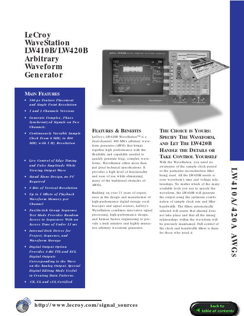
F EATURES& B ENEFITS LeCroy's LW420B WaveStation™ is a dual-channel, 400 MS/s arbitrary wave-form generator (A WG) that brings together high performance with the flexibility and capability needed to quickly generate long, complex wave-forms. WaveStation offers more than just great technical specifications. It provides a high level of functionality and ease of use while eliminating many of the traditional obstacles ofA WGs.Building on over 11 years of experi-ence in the design and manufacture of high-performance digital storage oscil-loscopes and signal sources, LeCroy's WaveStation combines innovative signal processing, high-performance design, and human factors engineering to pro-vide a truly intuitive and highly interac-tive arbitrary waveform generator. T HE C HOICE IS Y OURS:S PECIFY T HE W AVEFORM, AND L ET T HE LW420BH ANDLE THE D ETAILS OR T AKE C ONTROL Y OURSELF With the WaveStation, you need no awareness of the sample clock period or the particular reconstruction filter being used. All the LW420B needs is your waveform’s time and voltage rela-tionships. No matter which of the many available tools you use to specify the waveform, the LW420B will generate the output using the optimum combi-nation of sample clock rate and filter bandwidth. The filters automatically selected will assure that aliasing does not take place and that all the timing relationships within the waveform will be precisely maintained. Full control of the clock and bandwidth filters is there for those who need it.LeCroyWaveStationLW410B/LW420BArbitraryWaveformGeneratorLW410A/420A AWGSR EAL -TIME W AVEFORM M ANIPULATION L ETSY OU Q UICKLY C ONTROL T HE W AVESHAPE —E ASILY AND I NTERACTIVELY —W HILE V IEWING ON THE I NTERNAL CRT D ISPLAYSelect a section of the waveform using the time cursors, then select one of a set of waveform manipulation opera-tions (e.g. move feature, delay, ampli-tude) and turn the knob! That is how easy it is to continuously modify all or part of a waveform. Time shifts, as small as 100 ps, amplitude variations on a peak, or changes in signal dura-tion are instantly reflected in the output signal. Margin testing or characteriza-tion, with the most complex wave-forms, has never been so easy.W AVEFORM C REATION H AS N EVER B EEN E ASIERWaveforms can be selected from libraries of traditional functions or application specific waveforms. They can also be created using equations or imported from external sources such as oscilloscopes, or from computer pro-grams and simulator output files. Once waveforms are created or captured,they can be further modified using internal waveform (array) math pro-cessing. The waveform math functions include basic arithmetic operations,smoothing, integration, differentiation,and convolution.The highly developed waveform edit-ing capability uses advanced signal processing to provide bandlimited cut,paste, insert and offset operations with minimal editing artifacts. Single sample resolution, further simplifying wave-form creation, is allowed since wave-forms are not constrained to 8 sample multiples as with most other A WGs.To simulate real-world signals, the internal, asynchronous, wide-band noise generator is easily used to add controlled amounts of noise to your signals—simply dial in the noise level as a percentage of your signal’s ampli-tude. A real timesaver is that if youvary the signal’s amplitude, the signal-to-noise ratio is maintained.F LEXIBLE W AVEFORM I MPORT A ND T RANSFERPull waveforms directly from most digi-tal scopes; Connect a GPIB cable between the LW420B and your digital oscilloscope. Select your scope from a list of commonly available models and begin importing waveforms.Waveforms of up to 1 Mpoints in ASCII or from programs such as MathCad,MATLAB, PSPICE, IQSIM, TOPSIM and others can be imported from the floppy drive. You can also use a shareware program from LeCroy to convert your files to DIF format and transfer directly over the GPIB to the LW420B.When importing or transferring files,you have the choice of over sampling or importing the points exactly as they are. Once in the WaveStation, all the modification, editing and math tools can be used to put the waveform in the shape you need for your task.F AST S WITCHG ROUPS EQUENCE I NCREASES T EST F LEXIBILITY ANDM INIMIZES T EST T IMELeCroy’s Fast Switch Group Sequence capability enables you to switch between many different pre-loaded waveforms in less then 11 ms.Waveforms will continually play until a sequence advance is received from the front panel or a remote command.Choose to auto advance from sequence to sequence or choose to jump to the nth sequence in the group. Generate a continuous output of a sequence selected from the group, or use the external trigger input to initiate a burst or single shot of the selected sequence.D IGITAL O UTPUT O PTIONThe Digital Output option provides 8-bit TTL and ECL digital outputs corre-sponding to the current value of the Channel–1 analog output. The latched digital data is held for the duration of the sample clock. The digital data,including the sample clock and its complement, are available via rear-panel connectors. The special digital editing mode is useful for creating and editing byte wide data patterns orselected bits and the standard “cut and paste” tools available for analog wave-forms can also be used.400 MS/S M AXIMUM C LOCK R ATE , 1 M POINT W AVEFORMS , ANDS YNTHESIZER T IMEBASE W ITH T WO P HASE -S YNCHRONIZED C HANNELSA maximum sample rate of 400MS/s,up to 1Mbyte of waveform memory, a precise timebase, and single point reso-lution gives you the power you need to generate the most demanding, com-plex stimuli. The timebase combining 3 ppm accuracy and 1 ppm/year stabil-ity assures that the waveforms you test your systems with next year will be the same as the ones you use today. Low single sideband phase noise and a 1 Hz frequency resolution over a con-tinuous 6 kHz–400 MHz range provide the flexibility and capability needed to generate even the most complex and demanding waveforms.F ULLY I NTEGRATED AWG I NCLUDESH IGHP ERFORMANCE P ROCESSOR ,I NTERNAL H ARD D ISK D RIVE , A ND B UILT -IN 9I NCH CRTWaveStation provides all the power needed to work with long and com-plex waveforms. A built-in hard disk drive, a 486 processor, up to 24 Mbytes of RAM, and a large internal mono-chrome VGA display make the LW420A a fast, responsive instrument ideally suited for the interactive graphical operations required in a high-perfor-mance A WG.S I G N A L S O U R C E SLW410A/420A AWG SG ENERATOR M ODEStandard Function Waveforms Sine, 1 Hz–100 MHz Square, 1 Hz–50 MHz Triangle, 1 Hz–25 MHz Ramp, 1 Hz–25 MHzPulse, (period) 20 ns - max. memory DCFrequency Sweep, Linear / Log Multitone, 1–10 tones,1 Hz–100 MHzSpecial Waveform Generation Mode IMD - Intermodulation distortion test waveform: Select center frequency, 1-15 tone pairs, tone spacing, resolu-tion, offset from center frequency.A RBITRARY F UNCTIONSWaveform CreationInteractive Graphical editor on internal 9” diagonal CRT—8.5” viewable.Standard FunctionsSine, Square, Triangle, Ramp, Pulse, DCEquation EditorWaveform (array) Math Waveform Import From Digital Oscilloscope Floppy Disk Feature Time Resolution:100 ps @ 400 MHz Available memory:256 k/ch standard 1 Mpoint optionalS EGMENTED W AVEFORMSMinimum segment length:64 points Maximum segment length:Up to available memory (1 Mpoint with memory option installed).Segment length resolution:1 point Number of links: 512 for 256k memory 2048 for 1M memoryW AVEFORM O UTPUT C HARACTERISTICSOutput channels:LW410A – 1 Channel LW420A – 2 ChannelOutput Impedance:50 Ω, ±5%DC Accuracy:2% ±40 mV >500 mV 2% ±15 mV <500 mV Vertical resolution:8 bits Minimum output voltage: 10 mV p-p into 50 ΩMaximum output voltage: 10 V p-p into 50 ΩOffset voltage range:±5 V into 50 Ω.The output voltage (signal + offset)must be in the range ±5 V into 50Ω.Offset voltage resolution:0.05% of full scaleOutput bandwidth:100 MHz (-3dB)(widest bandwidth)Total harmonic distortion:For sinusoidal output of <5 V p-p; < -45 dBc (-50 dBc typical) forfrequencies: <1MHz < -35dbc (< -45 dBc typical) forfrequencies: 1 MHz–20 MHz < -25 dBc (< -40 dBc typical) forfrequencies: >20MHz–50 MHz, predominantly 2nd harmonic Spurious & non-harmonic distortion:< -60 dBc for frequencies <1 MHz Signal-to-noise ratio:>40 dB (-45 typ-ical) for output amplitudes >100 mV @0 offsetTransition times:5.0 ns, 10%–90% at widest bandwidth.Overshoot and ringing:<8% of step size max. 3% typicalSettling time: <50 ns to within 2% of step size at widest bandwidth.Inter-channel crosstalk:<1%Ch 1 to Ch 2 skew:<1 ns for identical waveforms in each channel (widest bandwidth).Output protection:±20 VOutput filtering: Gaussian filters with the following cutoff frequencies can be selected; 100 MHz , 10 MHz, 1 MHz ,100 kHz , 10 kHzS AMPLE C LOCK C HARACTERISTICS(with internal 10 MHz reference)Sample Clock: 6 kHz–400 MHz Resolution: 1 HzAccuracy:<3 ppm over operating tem-perature range.Stability:aging <1 ppm/yearSSB Phase Noise: < -90 dBc/Hz @ 10KHz offset for a 10 MHz sine wave at the outputT RIGGERINGC HARACTERISTICSTrigger slope: Positive or Negative Trigger input impedance:50 Ω±5%Threshold range:±2.5VThreshold resolution: 20 mV Threshold accuracy:100 mV Threshold sensitivity:50 mV p-p Minimum pulse width:5 ns Protection: ±5 VT RIGGER M ODESContinuous:Runs continuously Single: Outputs 1 repetition of the waveform for each trigger received.Triggers received while the waveform is still running are ignored.Burst:Outputs the selected waveform a programmable number of times in response to a trigger. The maximum number of repetitions for a burst is 4,095. Triggers received while the burst is running are ignored.Gated:The waveform starts on theleading edge of the gate signal and stops on completion of the waveform cycle occurring at the trailing edge of the gate signal.T RIGGER D ELAYMinimum delay time:35 ns ±3.5 ns +5 sample clocks (fixed)Maximum delay time:10 s at highest clock rate to 100k s at lowest clock rate.Delay resolution:1 sample clock.Delay is in units of seconds. When operating from the front panel, the res-olution is set in increments of the sam-ple clock period.Delay accuracy:Same as sample clock + minimum delay time.Delay jitter:1 sample clock.T RIGGER S OURCESManual:Front panel push-button.External:Front panel BNC connector.GPIB:A trigger command may be issued over the GPIB bus.M ASS S TORAGE3.5” 1.44 MB DOS format floppy drive 400 MB internal hard disk drive.A UXILIARY I NPUTSExternal 10 MHz reference:Rear panel BNC connector for input of an external reference clock. 400 mV p-p to 5 V p-p into 50 Ω.A UXILIARY O UTPUTS10 MHz reference: ±3 ppm accuracy Amplitude (high): 1.6V into 50 Ω.Amplitude (low): 0.2V into 50 Ω.Markers: Select Edge or Clock Edge: 1 bit memory—set up to 128edge transitions—ECL or TTL levels Clock: Frequency up to one half the sample clock rate.Protection:Outputs protected to ±5 V.Channel 1 Digital Output Optional:8 bits and clock with TTL and ECL logic levels available simultaneously. Noise In: From rear panel BNC connectors.H ARD C OPY O UTPUTSSupported Printers include:Epson MX/FX Epson LQ HP LaserJet II HP ThinkJetP ROGRAMMABILITYGPIB IEEE 488.2 compatible.Compliant with SCPI programming lan-guage. Capable of initiating and con-trolling waveform transfer from digital oscilloscopes by simply connecting a GPIB cable (no computer required).M ECHANICALDimensions:14.92”W x 7.67”H x 19.58”D (37.9 cm x 19.5 cm x 49.7 cm)Weight:27.6 lbs (12.5 kilograms)E NVIRONMENTALTemperature:5º to 35º full specifica-tions; 0º to 40ºC operating;-20º to 70ºC non-operating.Humidity:10% to 90% relative, non-condensingP OWER :Autosensing90-132/180-250 V AC 47-63 Hz4 amps @ 115 V AC(20 amps cold start surge)2 amps @ 230 V AC(40 amps cold start surge)Warranty:One YearS I G N A L S O U R C E S。
GWF410资料

GAMEWELL-FCI12 Clintonville Road, Northford, CT 06472-1610 USA • Tel: (203) 484-7161 • Fax: (203) 484-7118Specifications are for information only, are not intended for installation purposes, and are subject to change without notice. No responsibility is assumed by Gamewell-FCI for their use.©2007 by Honeywell International Inc. All rights reserved. 9021-60294 Rev. A page 1 of 2Flex Series GWF41010 Zone Expandable ConventionalFire Alarm Control PanelDescriptioni 3™ is a trademark of Honeywell International Inc.UL ® is a registered trademark of Underwriter’s Laboratories, Inc.Windows ® is a registered trademark of Microsoft Corporation.The Flex 410 is a ten zone fire alarm control panel (FACP)expandable to twenty or thirty zones using optional CZM-400 zone expander module(s). The Flex 410 is ideal for a wide range of different sized installations such as hotels,schools, correctional institutions, health care facilities,small office buildings, and manufacturing plants. Initiating device circuits (IDCs) for the Flex 410 can be pro-grammed as either ten Class B (Style B) or five Class A (Style D) circuits. This is expandable to either twenty Class B (ten Class A), or thirty Class B (fifteen Class A) IDC cir-cuits. The panel is compatible with a variety of conven-tional two-wire smoke detectors, four-wire smoke detectors, and notification appliances. This includes Sys-tem Sensor i 3™ Series microprocessor-based detectors with advanced features like drift compensation, mainte-nance alert and freeze warning. (See Appendix A of the Flex 410 Installation & Operations Manual PN 151321 for a list of compatible devices.)Outputs include four Class B (Style Y) or two Class A (Style Z) supervised notification appliance circuits (NACs)to annunciate alarm conditions. NAC circuits support single circuit synchronization, regulated. Three programmable auxiliary relay outputs can be programmed to activate (for all zones or individual zones): pre-alarm, fire alarm, auxil-iary alarm, alarm by zone and system or circuit troubles (e.g., loss of AC, low battery, communication failure, phone line trouble, fire drills, and NAC trouble).The Flex 410 includes a built-in digital alarm communicator (DACT) to report status to a central station. A user-friendly,two-line LCD display and tactile keypad makes system pro-gramming and control easy. The Flex 410 cabinet can be flush- or surface-mounted and a Plexiglas window/dead-front door kit is available where jurisdictions require. The fully regulated, efficient 6-amp power supply with charger ensures adequate power is available at all times.The Flex 410 fire alarm control panel is listed to UL ® Standard 864, 9th Edition.Features•10 Class B (Style B) or 5 Class A (Style D) initiating device circuits (IDCs), expandable up to 30 Class B or 15 Class A IDCs with optional zone expander(s)•Supervised zone expanders and I/O modules can be mounted remotely in optional accessory cabinet •All zones compatible with 2- and 4-wire detectors•Built-in digital alarm communication transmitter (DACT) with dual phone line monitors• 4 Class B (Style Y) or 2 Class A (Style Z) supervised notification appliance circuits (NACs)•Selectable/programmable NAC output patterns:- ADA compliant strobe synchronization- ANSI audible signals as required by NFPA 72- Single Stroke BI - Constant output - California code - March code(continued next page)GWF4107165-1288:182SIGNALINGS521An ISO 9000-2000 CompanyGAMEWELL-FCI12 Clintonville Road, Northford, CT 06472-1610 USA • Tel: (203) 484-7161 • Fax: (203) 484-71189021-60294 Rev. A page 2 of Features (continued)•Built-in 2-line, 32-character LCD display with easy-to-read English language readouts• 3 programmable general purpose relays •Built-in walk test•Programmable from keypad, remote annunciator, or using direct connect port for on-site downloading with SmartProgram 400 software (Windows ®-based)•Programmable features to minimize false alarms: smoke verification, pre-alarm delay, cross-zoning, and enhanced verification•Municipal box service and polarity reversal signaling •Programmable date settings for Daylight Savings Time, and clock source setting options for 50 Hz, 60 Hz or internal clockOptionsGWCZM-400Each GWCZM-400 zone expander pro-vides the control panel with ten additional Class B (Style B) zones or five Class A (Style D) zones. The GWCZM-400 con-nects to the control panel via the panel SBUS and is supervised and power limited.Up to two zone expanders can be used per panel. Mounts in FACP or into a GWCAB400-A accessory cabinet.GWIOM-410This status display module provides out-puts and control functions for remote annunciation of alarm, trouble, and supervi-sories for each zone. The system can supervise up to eight GWIOM-410 status display modules. Mounts in FACP or into a GWCAB400-A accessory cabinet.GWRAN-400 The GWRAN-400 remote annunciator canperform all system control operations. It also provides trouble and alarm information and can be used for programming. The FACP can support up to four GWRAN-400remote annunciators. Mounts in dual gang electrical box.GWCAB400-A This accessory cabinet is used for mount-ing GWCZM-400 zone expander and/or GWIOM-410 status display module.GWPLEX-2GA This door option combines a dead-frontpanel with a clear bicarbonate window to limit access to the control panel. Used for jurisdictions where single button operation is required.SpecificationsAC Power 120 VAC, 60Hz, 3 ABatteryMax. charging circuit: 27.4 VDC@ 0.75AMax. charger capacity: 33 Ah(two 18Ah batteries fit inside FACP)Operating Power 24 VDC operating voltage Total DC Load6 AInitiating Device Circuits (IDC)(2-wire smoke): 17.5- 27.4 VDCAlarm current draw (panel): 460 mA Short circuit current: 95 mA maximum Standby current draw (panel): 140 mA Maximum impedance: 50 ohms Accessory Power 27.4 VDC, 1 ANotification Circuits (NAC)27.4 VDC, 3 A max/output (6 A total)Maximum line impedance: 1.5 ohm Programmable 2.5 A, 24 VDC (inductive), 5 A, 24 VDC Relays (resistive), non-power limited Operating Range32° F to 120° F (0° C to 49° C)Flex 410 Cabinet 26 3/8" x 17 3/16" x 4" (67 x 44 x 10 cm)(H x W x D)Accessory Cabinet10 3/8" x 10 3/16" x 3" (26 x 26 x 8 cm)Ordering InformationPart NumberDescriptionGWF410Flex 410 FACP , 10 zones, expandable to 20 and 30 zones, 120 VAC GW151321Flex 410 Installation & Operation ManualOptions:GWCZM-400Zone expander module; adds 10 Class B or 5 Class A circuitsGWIOM-410Input / output relay, supervisory status moduleGWRAN-400Remote annunciator for Flex 410 GWCAB400-A Accessory cabinet for mounting GWCZM-400 or GWIOM-410GWPLEX-2GA Dead-front door with Plexiglas window SP400SmartProgram 400 for remoteprogramming of the Flex 410 using a PC (available only to authorized distributors at ESD extranet)。
联想旭日410系列笔记本电脑说明书

联想旭日410系列笔记本电脑说明书一、产品介绍1.1 外观设计联想旭日410系列笔记本电脑以简约时尚的外观设计融入了高科技元素,给用户带来全新的视觉享受。
机身采用精选金属材质,银色拉丝工艺使其更具质感,同时也提供了出色的整体耐久性。
1.2 配置参数该系列笔记本电脑搭载了强大的配置,为用户提供卓越的性能和流畅的使用体验。
处理器选用英特尔酷睿 i5 四核处理器,主频高达2.5 GHz,同时拥有8GB 内存和256GB SSD硬盘,充分满足用户在办公、娱乐和学习中对于速度和容量的需求。
1.3 显示效果联想旭日410系列笔记本电脑配备了一块15.6英寸全高清显示屏,分辨率达到1920x1080,色彩饱满且清晰度极佳。
用户可以尽情享受高清影片、游戏和图片的细腻画质,带来身临其境的视觉体验。
1.4 操作系统与软件支持该系列笔记本电脑搭载了最新版本的Windows操作系统,为用户提供更流畅、更安全的操作环境。
同时,联想还提供了一系列实用软件,如办公软件套件、多媒体播放器等,以满足不同用户的各种需求。
二、使用说明2.1 开机与关闭在使用联想旭日410系列笔记本电脑之前,请确认电源适配器已连接电源,并检查电池是否已安装。
长按电源键开启电脑,系统将自动启动;点击开始菜单,选择关机,系统将执行关机操作。
在电脑开启或关闭过程中,请不要强制断电,以免损坏数据或硬件。
2.2 连接外部设备联想旭日410系列笔记本电脑支持多种外部设备的连接,请依据以下步骤进行操作:- 鼠标:将鼠标的USB接口插入电脑的USB接口,系统将自动识别并安装鼠标驱动。
- 打印机:连接好打印机和电脑,并确保打印机已开机。
在系统设置中添加打印机,完成驱动安装后即可正常使用。
- 外接显示器:通过HDMI接口或VGA接口将外接显示器连接至电脑,然后按下Win+P组合键,选择所需的显示模式。
2.3 无线网络连接联想旭日410系列笔记本电脑支持Wi-Fi连接,用户可以根据以下步骤连接到无线网络:- 打开无线网络开关,确保Wi-Fi功能处于启用状态。
霍尼韦尔X4使用中文说明
Impulse X4 系列便携式复合气体检测仪操作说明书!重要提示:!在首次使用仪器以前请认真阅读本手册,您将会掌握仪器正确的使用方法和了解仪器的功能,包括操作,维护,功能设置等内容。
!为了使操作者更安全,请按照手册中的要求,定期对仪器进行标定。
!如果在使用过程中,遇到的故障或问题在本手册中没有提到,请直接联系制造商Zellweger Analytics,或联系当地的代理商/服务商。
!警告和注意:·更换任何元器件都有可能损坏仪器的本质安全结构。
·如果需要使用存储卡,请选用Zellweger Analytics 提供的存储卡(订货号2566-0435),使用其它的存储卡有可能损坏仪器的本质安全结构。
·在允许的储存期之后激活检测器,有可能影响仪器的使用性能和保质期。
·应使用许可的5号干电池,如劲量电池,不要使用质量低下的干电池,以免影响仪器的本质安全性能。
·在更换电池时,应同时更换2节型号相同的新电池。
·在电池欠压提示后,应尽快更换新电池,以免旧电池漏液损坏仪器。
·在低温环境下,电池的寿命会缩短。
·更换电池时,应该在安全环境下进行。
·当更换任何一个传感器的情况下,都需要对仪器进行标定。
·在每天使用以前,应完成仪器的自检过程。
·定期的对仪器用标气进行测试,检查声、光、振动报警是否正常。
·标定时应选用厂家或国家认证合格企业提供的标准气体。
·标定时应在良好通风的环境下进行,以避免污染。
·不要在仪器电量不足的情况下标定。
·不要在富氧的环境下使用本仪器。
·可燃气体传感器的灵敏度会受到高浓度硫化物,卤素化合物,含硅化合物,以及含铅气体或蒸汽的影响,也叫“中毒”,应避免在以上的环境中使用仪器,如果必须使用,则使用完后应对仪器进行检测和标定,以免影响以后的使用。
- 1、下载文档前请自行甄别文档内容的完整性,平台不提供额外的编辑、内容补充、找答案等附加服务。
- 2、"仅部分预览"的文档,不可在线预览部分如存在完整性等问题,可反馈申请退款(可完整预览的文档不适用该条件!)。
- 3、如文档侵犯您的权益,请联系客服反馈,我们会尽快为您处理(人工客服工作时间:9:00-18:30)。
FireWire 410中文用户手册FireWire410 简介FireWire410 是一个4 进10 出音频接口,它通过IEEE-1394 端口(俗称"火线")与计算 机进行连接。
如果你的计算机没有火线端口,只需向计算机经销商购买一块PCI 的火线卡, 便能与FireWire410 连接。
笔记本电脑通常都自备火线端口。
FireWire410 包装内带一条高质量的六针到六针1394 数据线,建议你使用它或相同品质 的火线与电脑连接。
如果电脑上只有四针火线接口,则需购买一条六针到四针的1394 数据 线。
另外需指出,FireWire410 使用六针的端口自供电,若使用四针的火线口,需要为 FireWire410 提供外部电源。
提示:火线口即是1394 口,在Sony 设备中又称iLink 口。
FireWire410 提供两个卡侬和大三芯的复合模拟输入口,可以连接话筒,也可接电吉它、 电贝司等乐器;八个大三芯模拟输出口及一对S/PDIF 的同轴、光纤输入/输出。
FireWire410 提供了高品质模拟、数字输入输出,支持24 比特的采样精度、96kHz 录音采样频率和192kHz 输出采样频率,S/PDIF 端口支持AC3 和DTS 双编码。
FileWire410 还提供了一进一出MIDI 端口,并有开关选择MIDI 输出或是旁通,可作为独立MIDI 接口使用。
FireWire410 具有简捷实用的软件控制系统,提供了跳线和调音台控制功能,为音频软 件虚拟了10 个输出通道。
你可任意分配输入端口到输出端,每个内部通道又支持具有超大 控制幅度的辅助发送。
FireWire 还提供了零延迟硬件直接监听和基于ASIO 的超低延迟软监 听;具有两个独立的耳机监听输出,信号来源可选择,并有独立增益控制;两个麦克风/乐器功放提供了电平控制和监测功能、48V 幻像电源、20dB 衰减和最大66dB 的增益。
特点评述和技术指标两个本底噪音极低的麦克/乐器功放,带增益控制、LED 监测显示、幻像供电和最大66分贝增益;两个模拟线路输入和八个模拟输出;S/PDIF 输入输出,具有莲花口及TOSLink 光纤口;采样频率从32kHz 到192kHz 可选;24bit 采样精度、96kHz 采样频率的两进八出模拟I/O 端口;输出端口1/2 支持24bit 采样精度、192kHz 采样频率的播放;两个耳机输出口,可选择监听信号来源,独立增益控制;具有一个可用软件分配设置的参数数值旋钮;一进一出的MIDI 口,可选择thru(旁通)以便独立于电脑工作;多模拟输出口,支持7.1 环绕立体声输出;频率响应20-40kHz ± 1dB;信噪比:104dB;动态范围:108dB;总谐波失真:0.00281%。
系统要求FireWire410 不支持98 或ME 系统。
并且对Windows 2000,需要SP3 或以上版本;对 Windows XP,需要SP1 或以上版本。
你可以访问Windows 的升级网站获得最新的系统更新。
Mac 系统中,FireWire410 支持Mac OS 9.2 及更高版本或Mac OSX 10.1.5 及其更高版本。
更早的苹果系统版本将不被支持。
Pentium III 500MHz 或更高;128MB 内存;Directx 8.1 或更高;Windows XP(SP1)或Windows 2000 (SP3)系统。
Macintosh G3 500MHz 或更高;128MB 内存(OS9),256MB 内存(OSX);OS 9.2 或更高,OS 10.1.5 或更高。
控制和连接(前、后面板图片请见原说明书)1. 麦克风/乐器输入——卡农口和大二芯的复合插口,支持非平衡乐器输入和麦克风平衡输入。
2. 麦克风/线路选择——此按钮用于在线路输入与麦克风输入之间进行切换。
将其按入时选择线路输入;按出时,麦克风或乐器输入被激活。
3. PAD——在输入电路中插入一20 分贝的衰减。
当输入增益已很小,而过载指示灯仍显示模拟信号电平过大时使用此PAD 按钮。
4. 输入增益调节——此为电位调节旋钮,用于控制麦克风/乐器的输入电平。
5. 信号指示灯——灯亮时表明麦克风/乐器端口有输入信号。
6. 过载指示灯——灯亮时表明麦克风/乐器的输入信号电平过大,此灯在距过载3 分贝时开始显亮。
7. 输出信号检测——两个4 分段LED 指示,用于检测输出端口的信号大小,在FireWire410 控制面板中可选择被检测的输出端。
参看控制面板使用获取详细信息。
提示:以192KHz 采样率输出时,信号检测将自动关闭。
8. 数值旋钮——用于控制和调节由FireWire 控制面板规定的总线电平。
默认为Output,这是用于总监听的常用选择。
其他选择还有:SW 返回——调节FireWire410 的10 个虚拟输出,用于从数字音频软件到控制面板上调音台的返回发送。
Output——调节FireWire410 八个模拟输出和两个数字输出。
Input——调节FireWire410 两个模拟输入和两个数字输入。
Phones——调节FireWire410 的耳机输出。
辅助发送——调节FireWire410 的辅助发送总线,由FireWire 控制面板规定的输入通道辅助发送。
提示:参看控制面板获取更多信息。
9. 耳机输出——标准1/4 英寸立体声TRS 耳机口。
分别有独立的电平控制、并可在FireWire 控制面板中设定其信号来源,默认的信号源为输出端口1/2。
10. 耳机电平控制——分别对其耳机输出口电平控制。
11. S/PDIF 输入/输出指示——S/PDIF IN 指示灯稳定显亮,表示S/PDIF 的输入端口被正确 连接;S/PDIF IN 指示灯闪烁显示,表示S/PDIF 的输入端口连接不正确,请检查信号源及信号格式。
S/PDIF OUT 指示灯稳定显亮,表示S/PDIF 输出已连通,否则即不通(S/PDIF 对同轴口和光纤口均同时输出)。
12. MIDI 旁通开关——按钮处于In 的位置,表明FireWire410 的MIDI 输入和MIDI 输出 端口正采用旁通模式,即MIDI 信号不通过软件而直接作为简单的MIDI 接口传输。
此功能在FireWire410 电源关闭时仍存在。
13. 电源开关——控制打开及关闭FireWire410 的电源。
提示:在关闭FireWire410 电源时,FireWire410 将监测是否有与之相关的应用程序正在 执行。
如果是,电源指示灯将闪烁显示,此时FireWire410 处于“低电”模式,它保持 与火线外围设备的连接并允许你重新打开FireWire410 来继续未完成的工作。
14. 幻像电源开关(指示灯)——按钮处于In 的位置,表示幻像电源开启,将给麦克风/乐 器输入端提供48V 的幻想供电,以供电容话筒使用。
提示:幻像供电对大部分现在技术的动圈话筒都无影响,但对许多鹅颈麦和一些老式的 动圈话筒则有损害。
15. 外部供电电源接口——若用4 针的火线口连接FireWire410,需在此接12V/1A 的直流电源供电。
16. MIDI 输入输出口——标准的5 针MIDI 输入输出口;当MIDI 旁通打开时,MIDI 信号 在输入输出之间直接通过。
17. 火线接口——双火线(IEEE-1394)口,你可以用其一连接电脑,另外一个连接外部设 备。
建议你只连接自供电的外部设备,若用火线供电可能会影响音质。
18. S/PDIF 同轴输入输出口——用同轴RCA 接口传输S/PDIF 数字信号。
输入口格式在 FireWire410 的控制面板中需要选择,而输出口则不必:同轴和光纤输出口都同时有信号。
FireWire410 控制面板中,同轴口输入是默认选择,如不改动则用此口做S/PDIF 的信号输入。
19. S/PDIF TOSLINK 输入输出口——用光纤口传输S/PDIF 数字信号。
要做输入使用须在 FireWire410 控制面板中更改设置。
20. 线路输出口1-8——8 个均为非平衡的1/4’’TS 接口,用于-10dB 级别的线路输出。
这些 输出口可以支持标准的7.1 声道输出(要求有相应的音频软件支持)。
监听时,默认使用端口1/2 做立体声输出。
你可以在FireWire410 的控制面板上选择配对的立体声输出、分配不同信号源进行混音。
21. 线路输入1/2——2 个非平衡的1/4’’TS 接口,用于-10DB 级别的线路输入。
其余面板前 的麦克风/乐器输入是平行的,仅在麦克风/线路转换按钮处于In 的位置时起作用。
硬件安装软件程序安装完成前,务必不要进行硬件设备的连接。
驱动安装完成后,将FireWire410 与计算机用火线端口连接。
要获取最新的驱动程序,请访问官方主页:。
软件安装提示:软件程序安装完成前,务必不要进行硬件设备的连接。
WindowsXP:1.将FireWire410 的驱动光盘放入光驱。
从开始菜单中选择运行(R)…,在弹出运行对话框中点击浏览,找到光驱盘,打开firewire410 文件夹,点击FW410_”…”Setup.EXE 图标。
安装程序将复制需要的文件到你的电脑硬盘中。
2.在运行程序过程中,你可能收到驱动程序未通过Windows 认证的警告,不用理它,选择继续安装即可。
3.安装过程中出现“DVD/CD Performance Enhancement”选择对话框,按默认方式选中。
安装完成后,会出现“Installed Successfully”对话框:接着你将被提示需要重新启动计算机。
4.重新启动计算机后,将FireWire410 与电脑连接,并把电源打开。
此时将出现安装新硬件对话框。
5.选择默认的安装:“自动安装新硬件”,点击下一步,Windows 将自己找到驱动文件所位 置。
6.完成安装后将第二次出现“发现新硬件”,用同样方法安装即可。
最后会出现“M-Audio FireWire 410 Installed Successfully”的信息,点击完成即可。
FireWire410 现在已准备就绪。
你可以在系统工具栏(桌面右下角)中看到M-Audio FireWire410 的控制面板图标。
点击就打开FireWire410 的控制面板。
Windows2000:1.将FireWire410 的驱动光盘放入光驱。
从开始菜单中选择运行(R)…,在弹出运行对话框中点击浏览,找到光驱盘,打开firewire410 文件夹,点击FW410_”…”Setup.EXE 图标。
安装程序将复制需要的文件到你的电脑硬盘中。
2.在运行程序过程中,你可能收到驱动程序未通过Windows 认证的警告,不用理它,选择继续安装即可。