印度电能抄表外文
自动抄表外文翻译

河北建筑工程学院本科毕业设计(论文)外文资料翻译院别:电气工程学院专业:电气工程及其自动化班级:电控102姓名:**学号: **********外文出处:CNKI(用外文写)附件:1、外文原文;2、外文资料翻译译文。
1、外文原文Automatic meter reading systemThe present invention relates to automatic meter reading. More particularly, the present invention relates to an automated system for remotely monitoring a plurality of utility meters on command from a host server via an RF outbound broadcast.BACKGROUND OF THE INVENTIONHistorically, meters measuring electrical energy, water flow, gas usage, and the like have used measurement devices, which mechanically monitor the subscriber's usage and display a reading of the usage at the meter itself. Consequently, the reading of these meters has required that human meter readers physically go to the site of the meter and manually document the readings. Clearly, this approach relies very heavily on human intervention and, thus, is very costly, time-consuming, and prone to human error. As the number of meters in a typical utility's service region has increased, in some cases into the millions, human meter reading has become prohibitive in terms of time and money.In response, various sensing devices have been developed to automatically read utility meters and store the meter data electronically. These sensing devices, usually optical, magnetic, or photoelectric in nature, are coupled to the meter to record the meter data. Additionally, the meters have been equipped with radio frequency (RF) transceivers and control devices which enable the meters to transmit meter data over an RF link when requested to do so. Hand-held devices have been developed which include RF transceivers designed to interface with the meters' RF transceivers. These hand-held devices enable the human meter reader to simply walk by the meter's location, transmit a reading request over an RF link from the hand-held device to the meter's receiving device, wait for a response from the meter's sensing and transmitting device, and then record, manually or electronically, the meter data.Similarly, meter reading devices have been developed for drive-by reading systems. Utility vans are equipped with RF transceivers similar to those described in the hand-held example above. The human meter reader drives by the subscriber's location, with an automated reading system in the utility van. Again, the meters are commanded to report the meter data, which is received in the van via an RF link, where the data is recorded electronically. While this methodology improves upon the previous approaches, it still requires a significant amount of human intervention and time.Recently, there has been a concerted effort to accomplish meter reading by installing fixed communication networks that would allow data to flow from the meter all the way to the host system without humanintervention. These fixed communications networks can operate using wire line or radio technology.FIG. 1 shows a conventional fixed communication network for automated meter reading (AMR) technology. As shown in FIG. 1, a fixed communication network having wire line technology in which utility meters 10 are connected to a wide area network (WAN) consisting of a suitable communications medium, including ordinary telephone lines, or the power lines that feed the meters themselves.One disadvantage of this approach has been that when a number of meters transmit meter data nearly simultaneously, the inherent latency on the wide area network results in packet collisions, lost data, garbled data, and general degradation of integrity across the system. To compensate for the collisions and interference between data packages destined for the central computer, due to the latency inherent in the WAN, various management schemes have been employed to ensure reliable delivery of the meter data. However, while this approach may be suitable for small systems, it does not serve the needs of a utility which monitors thousands or even millions of meters.In an attempt to better manage the traffic in the WAN, approaches have been developed wherein meter control devices similar to those described above have been programmed to transmit meter data in response to commands received from the central computer via the WAN. By limiting the number of meter reading commands transmitted at a given time, the central computer controls the volume of data transmitted simultaneously. However, the additional WAN traffic further aggravated the degradation of data integrity due to various WAN latency effects. Thus, while these approaches may serve to eliminate the need for human meter readers, reliance on the WAN has proven these approaches to be unsatisfactory for servicing the number of meters in the typical service region.Consequently, radio technology has tended to be the medium of choice due to its higher data rates and independence of the distribution network. The latest evolution of automated meter reading systems have made use of outbound RF communications from a fixed source (usually the utility's central station), directly to RF receivers mounted on the meters. The meters are also equipped with control devices which initiate the transfer of meter data when commanded to do so by the fixed source. The meters respond via a WAN as in the previous wire-based example. One disadvantage of these approaches is that there is still far too much interference on the WAN when all of the meters respond at about the same time. Thus, while these approaches reduce some of the WAN traffic (by eliminating outbound commands over the WAN), they are still unable to accommodate the large number of meters being polled.It is worthy of note that the wire-based systems typically use a single frequency channel and allow the impedance and transfer characteristicsof the transformers in the substation to prevent injection equipment in one station from interfering with receivers in another station. This built-in isolation in the network makes time division multiplexing less critical than for radio based metering systems. Typical fixed network radio systems also utilize a single channel to read all meters but the systems do not have a natural blocking point similar to the substation transformer utilized by distribution line carrier (DLC) networks. Also, the latency inherent in the WAN has contributed significantly to the problems associated with time division multiplexing a single frequency communications systems. As a result, the systems require sophisticated management schemes to time division multiplex the channel for optimal utilization.Therefore, a need exists to provide a system whereby a utility company can reliably and rapidly read on the order of one million meters in the absence of any significant human intervention. Further, a need exists to provide such a system which accommodates changes to the network as well as changes in operating conditions without significant degradation of performance.SUMMARY OF THE INVENTIONThe present invention fulfills these needs by providing an automated meter reading system having a host server interfaced to a plurality of nodes, each node communicating with a number of utility meters. In a preferred embodiment, the system has a selection means for selecting a group of noninterfering nodes; and an outbound RF broadcast channel from the host server for communicating with the selected group to initiate the reading of meters that communicate with those nodes and the uploading of meter data provided by those meters to those nodes. This outbound RF broadcast channel can be an existing channel currently being used for demand side management. In a preferred embodiment, the system also has a two-way communication link over a wide area network between the host server and each of the nodes. In a more preferred embodiment, the host server receives meter data read from at least one million meters in no more than about five minutes.In yet another preferred embodiment, the system also has a number of gateways, each communicating with a plurality of nodes, grouped to form sets of noninterfering gateways. In this embodiment, the system also has a selection means for selecting one of the sets of noninterfering gateways, and a second outbound RF broadcast channel from the host server for communicating with the selected set to initiate uploading of meter data from the selected set to the host server. This second outbound RF broadcast channel can be an existing channel currently being used for demand side management.The present invention further fulfills these needs by providing a method for using an outbound RF channel to automatically read meters. Ina preferred embodiment, the method comprises the steps of: defining a number of groups of noninterfering nodes: selecting a first group; broadcasting a read command to each node in the first group; selecting a second group; and broadcasting a read command to each node in the second group.In another embodiment, the method further comprises the steps of: reading meter data, in response to the read command, from each meter communicating with the node receiving the read command; recording the meter data in a data storage means associated with that node; broadcasting an upload message to each node in the first group; uploading the meter data recorded in the data storage means associated with the nodes of the first group to the host server; broadcasting an upload message to each node in the second group; and uploading the meter data recorded in the data storage means associated with nodes of the second group to the host server.In yet another embodiment, at least some of the nodes communicate through one of a number of gateways to the host server. In this embodiment, the method further comprises the steps of: selecting a first set of noninterfering gateways; broadcasting an upload message to each gateway in the first set; uploading the meter data recorded in the data storage means associated with the nodes that communicate with the first set of noninterfering gateways to the host server; selecting a second set of noninterfering gateways; broadcasting an upload message to each gateway in the second set; uploading the meter data recorded in the data storage means associated with nodes that communicate with the second set of noninterfering gateways to the host server.The present invention further fulfills the aforementioned needs by providing an automated meter reading system wherein the host server maintains a topology database in which each meter is assigned to at least one node, each node is assigned to at least one gateway. The nodes are preferably grouped together to define groups of noninterfering nodes and the gateways are preferably grouped together to define sets of noninterfering gateways.In another preferred embodiment, each of the plurality of nodes is adapted to receive RF broadcasts and the host server sequentially broadcasts a communication over an RF channel to each group of noninterfering nodes to initiate meter reading. In yet another preferred embodiment, each of the plurality of gateways is adapted to receive RF broadcasts and the host server sequentially broadcasts an upload message over a second RF channel to each set of noninterfering gateways, the gateways uploading the meter data to the host server via a wide area network in response to the upload message.The present invention further fulfills these needs by providing a method of automatically reading a plurality of meters in an AMR systemcomprising the steps of: selecting one of the nodes designated to communicate with each gateway; grouping the selected nodes to form groupsof noninterfering nodes; forming sets of gateways such that each gatewaywithin one set has an individual gateway designator; maintaining atopology database that uniquely identifies for each meter the set, gatewayand node designators associated with said meter; and reading the metersbased on the set, gateway and node designators.In another preferred embodiment, the method further comprises thestep of initiating meter reading by sequentially broadcasting a read message over an RF channel to each group of noninterfering nodes. In yetanother preferred embodiment, the method further comprises the step ofinitiating the uploading of meter data by sequentially broadcasting anupload message over the RF channel to each group of noninterfering nodes.The present invention will be better understood, and its numerousobjects and advantages will become apparent by reference to the followingdetailed description of the invention when taken in conjunction with thefollowing drawings, in which:FIG. 1 shows a conventional fixed communication network for automatedmeter reading technology;FIG. 2 shows a block diagram of an automated meter reading system according to the present invention;FIG. 3 shows a block diagram of an automated meter reading system inwhich an optional gateway is included according to the present invention;FIG. 4 shows a network of nodes and gateways exemplifying a group of noninterfering nodes;FIG. 5 shows communications traffic within one set of gateway serviceregions in an automated meter reading system;FIG. 6 shows the process by which a host server commands groups of noninterfering nodes to read meters and by which nodes read and store meterdata gateways in accordance with a preferred embodiment of the present invention;FIG. 7 shows the process by which a host server commands nodes and gateways to upload meter data simultaneously in accordance with a preferred embodiment of the present invention;FIG. 8 shows the process by which a host server commands nodes and gateways to upload meter data by using groups of noninterfering gatewaysin accordance with a preferred embodiment of the present invention.DETAILED DESCRIPTION OF THE PREFERRED EMBODIMENTFIG. 2 shows a diagram of a preferred embodiment of an automated meterreading system which uses broadcast technology to read utility meters in accordance with the present invention. The system includes a host server,a wide area network (WAN), a plurality of optional gateway interface (OGI)nodes, and a plurality of utility meters 。
电力系统外文翻译
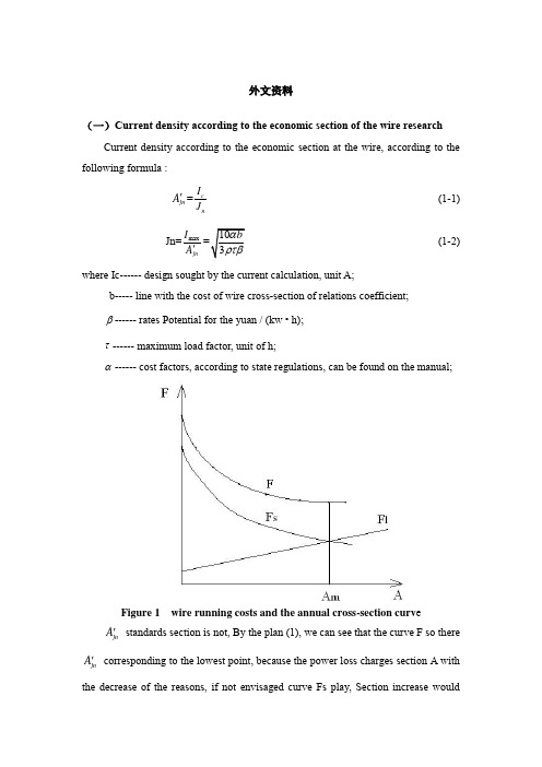
外文资料(一)Current density according to the economic section of the wire researchCurrent density according to the economic section at the wire, according to the following formula :jn A '=c nI J (1-1) Jn=max jn I A '(1-2) where Ic ------ design sought by the current calculation, unit A;b ----- line with the cost of wire cross -section of relations coefficient;β------ rates Potential for the yuan / (kw • h);τ------ maximum load factor, unit of h;α------ cost factors, according to state regulations, can be found on the manual;Figure 1 wire running costs and the annual cross-section curv ejn A ' standards section is not, By the plan (1), we can see that the curve F so there jn A ' corresponding to the lowest point, because the power loss charges section A with the decrease of the reasons, if not envisaged curve Fs play, Section increasewouldinevitably lead to the increase in operating costs. So admission standards section should not only satisfy the minimum requirements of the power loss, but also reduce running costs less because(1) In general, the establishment of factories or load a development process, the initial value is smaller than the design, gradually in order to achieve the expected value, butA'network is completed by the load considered, This is not consistentjnwith the actual situation, in other words, power loss is not designed so much to the imagination;(2) Design calculations indicate the actual load Ic than big design value;(3) F curve relatively flat bottom.Therefore, the selection criteria section, it should be by choiceA'smaller thanjnthe cross section, as F curve flat bottom, operating costs of less impact, taking into account the load values, as well as changes in the law, Theoretical calculation of the power loss will be larger than the actual value. with the options to save much of the initial investment and the consumption of non-ferrous metals.In the factory power supply system design using Jn wire cross section, Energy losses are still high volume of large factories into line and the electric network in the short occasions application. Method used Jn wire cross section still in use, but it should be noted that this method has the following problems :(1) 1.2 formula of the b value is not constant, the domestic tariff beta value is not uniform, Operating costs of Europium value in different countries should have the period of change.(2) This method is only from the operating expenses for at least the premise, not the investment, operating costs and the overall efficiency.Therefore, the proposed foreign books "at least expenditure," the wire cross section. Under Ic can elect to meet the heating requirements of the specifications 2-3 lead, their investment costs and operating costs are different. High investment costs of cross-section wire resistance by small and less power loss costs, it will be able to choose one of the best programs. But because the wire cross section Size is notcontinuous, but a broken line, in order to solve the lowest value to be used on the dogleg approximation method for the mathematical model, which is relatively more complicated, it has not been applied to engineering practice.(二)Grounding the researchCircuits are grounded in order to prevent high voltages from building up on the conductors, while equipment grounding aims at preventing enclosures from reaching voltages above ground. Grounding thus improves system protection and reliability and provides safety to people standing by.Grounding every circuit, however, makes the system susceptible to excessive currents should a short circuit develop between a live conductor and ground. Thus, not all neutrals of wye-connected loads (especially large motors) should be grounded. Grounding should then be practiced selectively, especially on the primary distribution system, as shown in Fig. -1. In part (a), disconnection of motors M1 and M3 for maintenance of repair deprives the 2400-volt system of a ground. It is preferable to ground the system at the source, that is, at the transformer neutral in Fig.-1 (b).2400V13.8kVM1M2M3M4(a)2400V13.8kVM1M2M3M4(b)Fig.2 Circuit grounding done selectively(a) at a few motor neutrals (load);(b) at the transformer neutral (source)Metal enclosures,raceways,and fixed equipments are normally grounded. However,motor and generators well insulated from ground,and metal enclosurs used to protect cables or equipments from physical damage,may be left ungrounded.Aslo,portable tools and home appliances,such as refrigerators and air conditions,need not be grounded if constructed with double insulation.Some ac circuits are required to be ungrounded as,for instance,in anesthesizing locations in hospital.In fact,line isolation monitors are installed in such cases,capable of sounding warning signals.High-voltage services (>1000V) are not necessarily grounded, but they must be so if they supply portable equipment.Metal underground water pipes are normally used for grounding, If their length is judged inadequate, they may be complemented by other means, such as a building metal frame or some underground pipe of tank.中文译文(一)按照经济电流密度选择导线截面的研究按照经济电流密度选择导线截面时,可根据下式:jn A '=c n I J (1-1) Jn=maxjn I A '(1-2)式中 Ic------设计时求得的计算电流,单位为A ;b-----线路造价与导线截面间的关系系数;β------电价,电位为元/(kw·h)τ------最大负荷损耗系数,单位为h ;α------费用系数,根据国家规定,可在有关手册中查到;图1 导线截面与年运行费的关系曲线jn A '未必是标准截面,那么,由图 1可以看出,曲线F 所以出现对应于jn A '的最低点,是因为电能损耗费随截面A 的增大而减小的缘故,设想如果没有曲线Fs 起作用,截面的增加必然引起运行费用的增加。
电气自动化专业英语词汇终极版

有公用备用干线的放射式radial system with public standby main line
树干式trunk system
单回路树干式one-circuit trunk system
单侧供电双回路树干式two-circuit trunk system with one-side power supply
电压波动voltage variation
电压标准voltage standard
电压等级voltage class
电压调整率voltage regulation rate
电流current
交流alternating current (A.C)
直流direct current (D.C)
短路电流short--circuit
备用电源standby source
应急电源emergency source
常用电源normal source
供电电压supply voltage
双回路供电two-feeder supply
两个独立电源two independent power supply
放射式radial system
单回路放射式one-circuit radial system
电压voltage
高压high tension (H.T)
低压low tension (L.T)
冲击电压impulse voltage
临界电压critical voltage
残余电压residual voltage
击穿电压breakdown voltage
供电电压supply voltage
电厂英汉对照表

F
FPO
抗燃油
flame proof oil
介质
F
FLTK
扩容器
flash tank
功能
F
FLW
流量
flow
单位
F
FNC
炉膛
furnace
专设
F
FLTR
滤网
filter
通设
F
FLUE GAS
排烟
flue gas
功能
F
FREQ
频率
Frequency
单位
F
FR
前
front
位置
F
F/B
前后
front / back
功能
A
ALM WIN
光字牌
alarm window
专设
A
ASH HOP
灰斗
ash hopper
专设
A
ACTIVE
激励
active
功能
A
AC
交流
alternating current
单位
A
AIR_S
空侧
air side
位置
A
AIR
空气
Air
介质
A
APH
空预器
air preheater
专设
A
AREA
区
area
状态
<
<
低于
<
状态
<
<
小于
<
状态
>
>
大于
>
状态
A
ALM
报警
alarm
印生物质发电项目技术方案中英文
印度xx生物质发电工程技术方案2015年6月目录1 总论(General) ........................................................1.1概述(Overview)..................................................1.2建设规模(Scale of Construction).................................1.3主要技术指标(Main Technical Index)..............................1.4主要设备(Main Equipment)........................................1.5 项目实施进度(Implementation Scheduling of the Project).........1.6投资估算(Investment Estimate)................................... 2燃料供应及烟风系统(Total static investment)...........................2.1设计标准(Design Standard) ......................................2.2燃料供应系统(Fuel Supply System) ...............................2.3烟风系统(Flue Gas and Air System) .............................. 3锅炉及辅机系统(Boiler and the Auxiliary System).......................3.1设计采用的规程、规范及标准(The Regulations, Specification and Standards Adopted in the Design).................................................3.2锅炉的布置与结构(Arrangement and Structure of the Boiler) ......3.3汽水流程(Steam/ Water Process) .................................3.4 锅炉排污、疏放水、汽水取样(Boiler Blowdown, Water Drainage and Steam/ Water Sampling)..............................................................3.5 锅炉给水及减温水系统(Boiler Water Supply and Attemperating Water System) .......................................................................3.6 锅炉技术参数(Technical Parameters of Boiler)...................3.7 锅炉特点(Boiler Features)......................................4 汽轮发电机组系统(Turbine Generator Set System).......................4.1设计中所采用的规程、规范(Regulations and Specifications Adopted in Design) .......................................................................4.2热力管道(Thermal pipe) .........................................4.3发电站热力设施(Thermal Equipment of Power Station) .............5尾气处理系统(Exhaust Gas Treatment)...................................5.1设计标准(Standards of Design) ..................................5.2 脱硫系统(Desulfurization System)...............................5.3 脱硝工艺(Denitrification System)...............................5.4烟气除尘系统(Ash Conveying and Dedusting System) ...............6 化学水系统(Chemical Water System)....................................6.1设计规范(Design Code) ..........................................6.2水处理方式(Selection of water treatment ways) ..................6.3水量的确定(Water consumption) ..................................7 循环冷却水系统(Circulating Cooling Water System).....................7.1设计规范(Design Code) ..........................................7.2系统冷却用水量(Water Consumption for System Cooling) ...........7.3设备冷却水系统方案(Plan for the Equipment Cooling Water System)7.4系统损失水量与补充水量(Water Loss Amount and Supplemented Water Amount of the System)............................................................8电气系统(Electric System).............................................8.1 编制范围(Compilation Scope )...................................8.2 电气技术方案(Electric Technical Plan ).........................9仪表自动化(Automation Instrument).....................................9.1 概述(Overview )................................................9.2 检测仪表的选型(Design Code)....................................9.3 自动化控制系统(Automatic Control System).......................9.4 仪表电源(Instrument Power Supply)..............................10 建筑及结构(Construction and structure)..............................10.1 建筑(Construction)............................................10.2 结构设计(Structural Design)................................... 11总图(General Drawings)...............................................11.1设计规范(Design Code) .........................................11.2 总平面布置(General Layout)....................................11.3道路设计(Road Design) .........................................11.4竖向设计和雨水排除(Vertical Design and Rainwater Drainage) ..11.5物料运输(Material Transportation) .............................11.6管线及沟道布置(Pipeline and Ditch Arrangement) ................11.7 绿化(Greening)................................................12 公辅系统(Auxiliary system)..........................................12.1给排水(Public auxiliary system) ...............................12.2暖通空调(HVAC) ................................................13 劳动定员(Manpower Quota)............................................1 总论(General)1.1概述(Overview)项目名称:印度生物质直燃发电项目。
电表出口标准指南

编制《指南》的目的:维护国家、行业整体和长远利益,提升我国电能表行业整体质量和管理水平,促进我国电能表技术的发展,带领我国电能表企业跨越发达国家设置的技术壁垒,促进企业扩大出口,使更多的企业能够进入到国际市场,稳定、持续地促进电能表产品扩大出口。
编制《指南》的原则:一是先进性原则——参照国际电工标准最新版本,为我国电工仪表制造企业开拓国际市场、特别是开拓欧美发达国家市场,冲破技术壁垒提供技术指导;二是实用性原则——结合我国电工仪表行业实际水平,全面分析研究了国际主要市场概况、技术标准情况以及差异,对我国企业开拓市场、扩大出口提出有具体的、有针对性的建议和指导意见。
《指南》由商务部科技司统一安排和部署,在编制过程中得到有关单位和领导的大力支持与指导,在此一并表示感谢。
参加编写的单位:中国机电产品进出口商会、华立仪表(集团)公司、全国电工仪器仪表标准化委员会、商务部国际贸易经济合作研究院等。
参加编写人员:史海燕、王兆宏、肖琪经、敖毅斌、陈波、徐人恒、朱中文、梁艳芬、张学庆、付丽、张久琴、王尚恩。
附录一:
目标市场标准目录
附录二:
目标市场技术规范目录。
indiawind

印度风电调研报告新疆金风科技股份有限公司2003年1月印度风电调研报告一、印度电力的发展自从1947年独立以来,印度电力新增装机98,500 MW,总装机容量已达到1,00,000 MW。
目前,印度正从农业经济向工业化和商业化转移。
印度拥有世界16%的人口,但仅有全球2%的电力消费,尽管印度的人均能源消耗只有9兆焦,与世界平均水平60兆焦的标准相差甚远。
过去10年中,印度商业能源的消耗以每年6%的速度增长,平均每年大约增加1775MW,今后这个比率将大幅度增加。
然而供求差距仍很大,印度目前严重缺电,另外常规能源发电成本也在上涨。
面对能源日益紧张的状况,印度工业界被迫寻求替代的能源资源。
作为其可持续发展的战略的一个重要部分,印度政府计划在今后的10年内新增装机1,00,000 MW,其中10%即10,000 MW计划使用可再生能源。
印政府在非常规能源的开发利用方面也实施了一系列措施和政策。
经过十几年的努力,取得了显著成绩。
在此期间风力发电的增长最为显著,联合国的环境问题咨询机构世界观察研究所最新发布的统计数据表明,印度的风力发电目前在发展中国家中处于领先地位。
印度事实上已成为世界上第四大风力发电国家。
世界观察研究所甚至将印度称为“风力发电超级大国”。
二、印度丰富的风能资源印度风电的发展开始于二十世纪八十年代后期。
国内有八个主要的州适合开发风能资源。
风能储量巨大,达45,000 MW,其中可开发容量为13,000 MW。
截止目前,印度已经安装了1,628 MW的风电,其中包括29个地点63MW的装机示范项目及1,565 MW的商业化项目,风力发电项目发出的年发电量已超过37亿度。
可再生能源为印度提供了约为10,000-12,000 MW的电能,其中50%以上来自于风能,并将以每年500-600 MW的速度增长。
印度有两种类型的季风1、西南季风:西南季风每年四月从印度洋开始盛行。
平均风速在7月并在以后达到最大。
印度生物质发电项目技术方案中英文

印度生物质发电项目技术方案中英文The latest revision on November 22, 2020印度xx生物质发电工程技术方案2015年6月目录1 总论(General)1.1概述(Overview)项目名称及承办单位(Project name and organizer)项目名称:印度生物质直燃发电项目。
Project Name: Power Generation Project of India.设计依据(Design basis)依据中华人民共和国电力工程国家标准、行业标准、规范等。
National standards, industrial standards and regulations of the People’s Republic of China on electric power engineering shall prevail.业主提供的相关数据及资料。
Relevant data and materials provided by the owner业主所在地相关法律法规。
Relevant laws and regulations in the place where the owner resides 工程范围(Scope of project)本工程主要对电厂生产所必须的燃料供应、发电工艺、电气出线、电站公辅设施等进行分析,最终推荐技术可行、经济合理的混合燃料直燃发电站方案。
This project is mainly to analyze the fuel supply, power generation process, electric outlet line and power station public auxiliary facilities needed by the power plant, and finally recommend a technically feasible, economic and reasonable plan for combined fuel power generation station.设计内容具体包括:燃料供应及烟气系统、锅炉及辅机系统、汽轮机发电机组系统、化学水处理系统、循环冷却水系统、供配电、自动化控制系统以及相关配套的土建、通讯、给排水、照明、环保、劳动安全与卫生、消防、供暖等辅助系统。
- 1、下载文档前请自行甄别文档内容的完整性,平台不提供额外的编辑、内容补充、找答案等附加服务。
- 2、"仅部分预览"的文档,不可在线预览部分如存在完整性等问题,可反馈申请退款(可完整预览的文档不适用该条件!)。
- 3、如文档侵犯您的权益,请联系客服反馈,我们会尽快为您处理(人工客服工作时间:9:00-18:30)。
AUTOMATIC ELECTRIC METER READING SYSTEM: A COST-FEASIBLE ALTERNATIVE APPROACH IN METER READING FOR BANGLADESH PERSPECTIVE USING LOW-COST DIGITAL WATTMETER AND WIMAX TECHNOLOGYTANVIR AHMED1, MD SUZAN MIAH2, MD. MANIRUL ISLAM3 and MD. RAKIB UDDIN4ABSTRACTEnergy meter reading is a monotonous and an expensive task. Now the meter reader people goes to each meter andtake the meter reading manually to issue the bill which will later be entered in the billing software for billing andpayment automation. If the manual meter reading and bill data entry process can be automated then it wouldreduced the laborious task and financial wastage. “Automatic Electric Meter Reading (AMR) System” is ametering system that is to be used for data collecting from the meter and processing the collected data for billingand other decision purposes. In this paper we have proposed an automatic meter reading system which is low cost,high performance, highest data rate, highest coverage area and most appropriate for Bangladesh perspective. Inthis AMR system there are four basic units. They are reading unit, communication unit, data receiving andprocessing unit and billing system. For reading unit we identified the disk rotation of the energy meter and storedthe data in microcontroller. So it is not required to change the current analog energy meter. An external modulewill be added with the current energy meter. In the communication unit Wimax transceiver was used for wirelesscommunication between meter end and the server end because of its wide coverage area. In the data receiving andprocessing unit meter reading will be collected from the transceiver which is controlled by another microcontroller.There will be a computer application that will take the data from the microcontroller. This will also help to avoidany tampering or break down of energy meter. There are various AMR system exists all over the world. Thosesystems were analyzed and we found they are not feasible for Bangladesh. Our proposed system is completely newand is appropriate for Bangladesh perspective. The study was conducted at the Electrical Circuit Laboratory,American International University, Dhaka, Bangladesh during October 2009 to November 2010.Keywords: Digital wattmeter, AMR, WiMax and PLM.I NTRODUCTRIONAutomatic Meter Reading System (AMR) is the remote collection of consumption data from customers' utility like Electric meters using radio frequency, telephony, power-line or satellite communications technologies and process the data to generate the bill (Moghavvemi et al., 2005). Now a day, AMR is heavily used in the abroad for collecting reading and billing purpose. In Bangladesh the electricity billing system is completely manual. The electric meters are situated in the houses, offices and factories etc .Meter readers go to the place which are generally situated inside the house and take the meter reading. Most of the time the owner gives some extra money to the meter reader person to have less meter reading. As a result corruptions occur and actual payment is not received by the service provider. So the provider faces a huge amount of loss in every year. At this present situation, it’s very necessary to implement AMR in Bangladesh. Millions of Analog meters are already used in our houses, offices, industries. So we are not proposed any new meter. We want to develop a miniature module which will take reading from analog meter and then convert this data into digital data. And this module also responsible for transmission of data to the provider end. At the provider end there will be another module which is responsible for data receiving. And this module makes an interface with computer which is responsible for data processing. Automatic meter reading, or AMR, is the technology of automatically collecting data from energy meter or water metering devices (water, gas, and electric) and transferring that data to a central database for billing and/or analyzing. This means that billing can be based on actual consumption rather than on an estimate based on previous consumption, giving customers better control of their use of electric energy, gas usage, or water consumption (/index.php?page=ecm-definition). Automatic meter reading was first tested 30 years ago when trials were conducted by AT&T in cooperation with a group of utility companies and Westinghouse. After those successful experiments, AT&T offered to provide phone system-based Automatic Meter Reading services at $2 per meter the price was four times more than the 1Department of Computer Science, American International University-Bangladesh (AIUB) Dhaka, Email: tanvir@, 2Department of Electronics and Information System, Politecnico Di Torino Turin, Italy, Email : sznmiah@, 3Department of Computer Science, American International University-Bangladesh (AIUB) Dhaka, Email: manirul@ and 4Department of Pharmaceutical Chemistry, University of Dhaka, Dhaka, Bangladesh, Email : rakibuddin.md@.monthly cost of a person to read the meter-50 cents. Thus the program was considered economically unfeasible (/news/Automatic_Power_Reading.pdf). The modern era of automatic meter reading began in 1985, when several major full-scale projects were implemented. Hackensack Water Co. and Equitable Gas Co. were the first to commit to full-scale implementation of automatic meter reading on water and gas meters, respectively. In 1986, Minnegasco initiated a 450,000- point radio-based automatic meter reading system. In 1987, Philadelphia Electric Co., faced with a large number of inaccessible meters, installed thousands of distribution line carrier automatic meter reading units to solve this problem. Thus, automatic meter reading is becoming more viable each day. Advances in solid-state electronics, microprocessor components and low-cost surface-mount technology assembly techniques have been the catalyst to produce reliable cost-effective products capable of providing the economics and human benefits that justify automatic meter reading systems on a large, if not full-scale basis [10]. AMR technologies include handheld, mobile and network technologies based on telephony platforms (wired and wireless), radio frequency (RF), or power line transmission (Agustín Zaballos et al., 2009; John Newbury and William Miller, 2001; Vinu V Das, 2009; Xin Longbiao and Liu Chunlei. 2008 and Moonsuk Choi. 2008. Some existing meter reading techniques are: Touch Technology AMR, Radio Frequency AMR (Handheld, Mobile or "Drive-by" meter reading and Fixed Network AMR), Power Line Communication AMR, Wi –Fi.With touch based AMR (/et/issue0707/AMR_Evolving_Techology) a meter reader carries a handheld computer or data collection device with a wand or probe. The device automatically collects the readings from a meter by touching or placing the read probe in close proximity to a reading coil enclosed in the touchpad. When a button is pressed, the probe sends an interrogate signal to the touch module to collect the meter reading. The software in the device matches the serial number to one in the route database, and saves the meter reading for later download to a billing or data collection computer. As the meter reader has to go to the site of the meter, so this is not changing the current situation. Radio frequency based AMR (Rob Kavet and Gabor Mezei. 2010) can take many forms. The more common ones are Handheld, Mobile, and Fixed network. There are both two-way RF systems and one-way RF systems in use that use both licensed and unlicensed RF bands. Handheld AMR is where a meter reader carries a handheld computer with a built-in or attached receiver/transceiver (radio frequency or touch) to collect meter readings from an AMR capable meter. Mobile or "Drive-by" meter reading is where a reading device is installed in a vehicle. The meter reader drives the vehicle while the reading device automatically collects the meter readings. Fixed Network AMR is a method where a network is permanently installed to capture meter readings. This method can consist of a series of antennas, towers, collectors, repeaters or other permanently installed infrastructure to collect transmissions of meter readings from AMR capable meters and get the data to a central computer without a person in the field to collect it. Power line communication is very popular in AMR field (Agustín Zaballos et al., 2009; John Newbury and William Miller, 2001; Xin Longbiao and Liu Chunlei, 2008; Xin Longbiao and Liu Chunlei, 2008 and Moonsuk Choi, 2008). Power line (PLC) AMR is a method where electronic data is transmitted over power lines back to the substation, then relayed to a central computer in the utility's main office. This would be considered a type of fixed network system the network being the distribution network which the utility has built and maintains to deliver electric power. Such systems are primarily used for electric meter reading. Some providers have interfaced gas and water meters to feed into a PLC type system.All of the above technology have some limitation and is not feasible for Bangladesh perspective. In the touch technology, handheld technology and in mobile technology still the meter readers have to go to the houses, offices and other places where the meters are placed. So still the meter reader person is required. In addition we need extra devices which are very expensive. As a result they are not cost feasible. The PLC technology is not also feasible for Bangladesh perspective. In Bangladesh high voltages transmits through the power line cable. As the voltage is high so the transmitted data will be corrupted by the attenuation. All the power line cable of our country is not placed under the ground. It situated in the open air. So the cable faces different environmental problems. So the actual data may not transmit to the provider end. As a result this technology is also not feasible in our country. The fixed RFtechnology has small coverage area. As a result, this method consist of a number of series of antennas, towers, collectors, repeaters, or other permanently installed infrastructure to collect transmissions of meter readings from AMR capable meters. So this is not cost efficient for the customers. The main objective of this paper is to introduce an AMR system which is cost efficient. Some other important objectives are: i. to reduce data collection costs, ii. To improve meter reading accuracy, iii. to enable faster, more efficient reading times and billing process, iv. Significantly increase operational efficiency by providing real time pricing and time-of-use metering, v. to improve customer service and vi. enable conservation of resources.METHODOLOGYIn this research we analyzed the existing meter reading system of our country and found out the different problems of the present system. We studied the different technologies available in the world to reduce the meter reading problems and modeled out a feasible solution for our country. We have visited different areas of Dhaka city and interviewed the inhabitants of the areas. A number of web site and research papers have been studied to produce a good and feasible model for Bangladesh perspective. It was 8 months long research. The study was conducted at the Electrical Circuit Laboratory, American International University, Dhaka, Bangladesh during October 2009 to November 2010. EXPERIMENTS AND FINDINGSP ROPOSED MODELAlmost all the meter reading systems consists of three primary components. We divided the whole AMR system into four basic units. These are: Reading unit, Communication unit, Data receiving and processing unit, billing system.Fig. 1. Block Diagram of whole AMR system.Reading unitIn this part basically two important jobs have been done. At first the analog meter reading was converted to digital bits sequence (0 or 1). After that the data are available in the microcontroller for transmission. First challenge is how we can get reading automatically from analog digital watt meter. It was analyzed that the rotations of the disk of the meter are needed to be counted. If it is possible to measure the number of rotation of the disk of the meter then the meter reading can be calculated. There are various types of sensors are available. Infrared can be used as a sensor. The infrared transmitter generates frequency and the receiver receives it. If there is no obstacle between the infrared transmitter and the infrared receiver than the infrared receiver give one value. But if there is any obstacle then the receiver gives another value. So this event can be used to count the rotation of the disk. The infrared transmitter and receiver have to place in such a way so that when the disk of the meter rotates it can recognize. A small hole is needed in the disk of the meter and the infrared transmitter and receiver should be placed in two opposite side of the disk of meter. They should be placed very close to each other so that when the hole cross the infrared then the transmitter and receiver can communicate. As a result when the disk is rotating the infrared can’t communicate, but when the hole will come in between the infrared transmitter and the infrared receiver then they can communicate with each other. So a signal can be found for each time just after passing the hole which indicating that the disk is rotated by one. To control the infrared microcontroller is used i.e. required voltage for the infrared was supplied from the microcontroller. A microcontroller instruction has been written for the infrared transmitter to transmit the frequency and made the infrared receiver active by giving high signal. A circuit diagram was used to implement this. An application program has been written and burnt it in the microcontroller.A LED display was used which indicated that the infrared transmitter and receiver is working or not. If the communication established i.e. the hole found between the infrared transmitter and receiver then the LED will turned on and it will turn off if the hole is not found means there is no communicationbetween the transmitter and receiver. To implement the reading unit some electrical components like infrared sensors (transmitter, receiver), resistors, Light Emitting Diode (LED) were used. For proper operation of the IR transmitter a 220 ohm resistor was connected. And the VDD was supplied to the IR transmitter through the pin7 (P7) of the microcontroller. Another part of the IR Transmitter was connected with VSS. The IR Receiver contains three PIN and was connected with VDD, VSS and the pin8 of the microcontroller as like the figure.Fig. 2. Circuit diagram of reading units.When the hole came between the infrared transmitter and receiver then the value of pin8 become 0 (zero). If the value is zero then a counter was incremented by one. Depending on the meter the unit can be calculated from the value of the counter. As a result the unit is stored in the microcontroller and is available for transmission. An example of the implementation picture is given in fig. 3.Fig. 3. Sample Implementation.So the basic steps for taking the meter reading are as follows:At first made a small hole in the disk of current existing meter -> Place the infrared sensor in specified way -> Check the hole -> If hole found increment the counter -> And write the data in the EPROM of microcontroller. The flow chart will be like this:Fig. 4. Sample Flow chart of the basic steps of reading unit.Communication UnitThis is one of the most important and challenging part of this system. This part is challenging in that sense, data is the most valuable part for meter reading and billing system. Data should be transmitted in an efficient manner without any loss of data. Let’s describe about this challenging part. From the above description it is clear that digital data is always ready for transmission. Meter reading are stored in Microcontroller’s EPROM and this data is always ready for transmission. But the main concern was how data can be transmitted efficiently? From the background study it is realized that all the existing communication units are not feasible for higher cost and infrastructure of Bangladesh. After studying different technologies, Wimax has been chosen for communication. In Wimax possibilities of data corrupting is very less. The coverage area is very high in Wimax and it is 10 km for NLOS communication. For the purpose of communication between meter end and the server end, a small miniature and low cost Wimax Transceiver module is required in each meter and in the server end. A transceiver module is a module which can transmit and receive data at a time. After searching a miniature and low cost transceiver module has been found.Fig. 5. Pin Information of AT86RF525B.The model name is AT86RF535B. AT86RF535B is a fully integrated, low cost RF 3.5GHz Low-IF/Zero-IF conversion transceiver for WiMAX applications. It combines excellent RF performance, small size, and low current consumption. The AT86RF535 chip is fabricated on the advanced SiGe BiCMOS process AT46000. The transceiver combines LNA, PA driver, RX/TX mixer, RX/TX filters, VCO, Synthesizer, RX Gain control, and TX Power control, all fully digitally controlled. This transceiver module is miniature in size. This Wimax transceiver module can be set up inside of the current analog wattmeter. And this transceiver also cost very lower than other transceiver. In the server end there will be a transceiver and each meter will contain a miniature transceiver. A computer application will run at the server end which can send an address of a particular meter to the microcontroller and the microcontroller will supply the address to the transceiver. Then the transceiver will send the address to all meters. Generally all the transceiver of the meters will be in sleep mode. When a transceiver of the meter receives the address sent by the server transceiver then it compares that is the request is for itself or not. If the request is for itself then it give a high signal to the microcontroller and the microcontroller send the data to the transceiver. After getting the data from the microcontroller the transceiver transmit the data. The server end transceiver receives the data and provides the data to the server end microcontroller. The microcontroller sends the data to the computer.This is the overall communication part of our system. Fig. 6 shows the data flow in communication unit of our proposed system.Fig. 6. Data flow in the communication units.Data receiving and processing unitThis is the third part of the proposed AMR system. In this part the received data is processed by the system for future purpose. For data processing purpose a computer application has been developed. The task of the application was to take a meter number form the user and give the address to the microcontroller through serial port. Then the microcontroller does the communication task. After communication part the microcontroller get the data form transceiver and the meter reading is available in the server end microcontroller. Then the data is sent to the computer and the computer application receives the data from the microcontroller. This data can be stored in the database and can be displayed to the requested user.Fig. 7. Block diagram of data receiving and processing unit.Billing SystemThe billing system has been developed in our system which can take the meter number and can generate bill for that meter. It uses the data of the database those are collected from the meter reading through all the unit of our system. This system also can be used for analysis on electricity usage for each meter.Fig. 8. Example on demand Reading using the computer application.Overall Conceptual designIn this system the existing analog meter will be used and our proposed miniature module will be added to each meter. A module will be situated in the server end and this module will be connected with the server computer. The entire module will be connected through Wi-Max technology. The overall conceptual design has given in fig. 9.Fig. 9. Conceptual Diagram of our proposed AMR.W IMAX AS A TRANSMISSION MEDIAWiMAX, the Worldwide Interoperability for Microwave Access, is a telecommunications technology aimed at providing wireless data over long distances in a variety of ways, from point-to-point links to full mobile cellular type access. It is based on the IEEE 802.16 standard, which is also called Wireless MAN. The name WiMAX was created by the WiMAX Forum, which was formed in June 2001 to promote conformance and interoperability of the standard ( /wiki/WiMAX ). WiMAX has a theoretical maximum bandwidth of 75Mbps. This bandwidth can be achieved using 64QAM 3/4 modulation. 64QAM can only be utilized under optimal transmission conditions. WiMAX supports the use of a wide range of modulation algorithms to enable the most bandwidth to be realized under all conditions (/wiki/WiMAX). WiMAX has a theoretical maximum range of 31 miles with a direct line of sight. Near-line-of-sight (NLOS) conditions will seriously limit the potential range. In addition, some of the frequencies utilized by WiMAX are subject to interference from rainfade. The unlicensed WiMAX frequencies are subject to RF interference from competing technologies and competing WiMAX networks. WiMAX can be used for wireless networking in much the same way as the more common WiFi protocol. WiMAX is a second-generation protocol that allows for more efficient bandwidth use, interference avoidance, and is intended to allow higher data rates over longer distances.Here is a summary of comparison:Table 1. Comparison of different wireless technology.Communication Technologies PLC UHF RADIO Wi-MaxData rate per connection 3.0 Mbps 9.5 Mbps 75 MbpsRange - 10 km 50 kmFrom the above table it can be understood that AMR with Wimax has better data rate and largest coverage area. If AMR using RF is used a large number of networking tools and resources will be needed. So the possibility of corrupting data is increased which is not feasible. We made a general consideration about Dhaka city. Over 20 lakhs household meter are available in Dhaka city. As the areaof Dhaka city is not a big one so only one server is enough to coverage the whole Dhaka city. Inaddition here the corruption of data will be less. So in cost and data both senses Wimax is the appropriate wireless technology for AMR in Bangladesh.B ENEFITS AND FUTURE WORKTangible benefits: In this system no meter reader is required. By using this system the real time meter reading is possible. Some other tangible benefits of our system are: Reduce the cost of meter reading with our low cost module, Detect meter tempering, No need to change current existing meter, Miss use of electricity will be decreased, Reduce of corruption done by the meter reader, Need based system, Monitoring the meter reading, Feasible for Bangladesh etc. As the system is automated, the retrieved data can be used for other purpose like online billing system, demand analysis, other analysis etc. Finally we can say that the service provider will get the actual bill.Intangible benefits: This system has some very important intangible benefits. As the service provider will get the actual bill, they will be satisfied by this system. The miss use of electricity will be decreased which will result reduced load shading. As the corruption is decreasing, the government will be benefited by this system. There will be no fake bill, so the customer will be satisfied. For future advancement more research can be done to develop meter reading for water meter and other types of meter reading.C ONCLUSIONAutomatic meter reading using Wi-Max technology is an excellent idea for Bangladesh perspective. We tried proposed a cost efficient AMR system. We also researched to make a feasible system for Bangladesh perspective. If it is implemented in our country the corruption of electricity sector will be reduced as well as the loss will also be reduced. So Bangladesh government should take necessary steps to implement Automatic meter reading system in our country.REFERENCESAgustín Zaballos, Alex Vallejo, Marta Majoral, and Josep M. Selga, 2009. “Survey and Performance Comparison of AMR Over PLC Standards”, IEEE transactions on power delivery, vol. 24, no. 2.John Newbury and William Miller. 2001.“Multiprotocol Routing for Automatic Remote Meter Reading Using Power Line Carrier Systems”, IEEE transactions on power delivery”, vol. 16, no. 1.Vinu V Das, 2009.“Wireless Communication System for Energy Meter Reading”, 2009 International Conference on Advances in Recent Technologies in Communication and ComputingXin Longbiao and Liu Chunlei. 2008.“Summary of Remote Meter Reading system Based On Carrier Power” Low-Voltage Apparatus. Beijing, April 2008, pp.1–4,9.Moonsuk Choi, Ju. Seongho Ju and Yonghun Lim. 2008, “Design of Integrated Meter Reading System based on Power-Line Communication”, Power Line Communications and Its Applications, 2008. ISPLC 2008. IEEE International Symposium on, pp. 280-284M. Moghavvemi, S.Y. Tan and S. K. Wong, 2005. “A reliable and economically feasible automatic meter reading system using power line distribution network”. International Journal Of Engineering -Materials And Energy Research Center. , Vol. 18, No. 3, pp. 301-318.Rob Kavet and Gabor Mezei. 2010, “A Perspective on Radio-Frequency Exposure Associated With Residential Automatic Meter Reading Technology”, Electrical Power Research Institute./wiki/WiMAX/et/issue0707/AMR_Evolving_Techology.pdf/news/Automatic_Power_Reading.pdf/index.php?page=ecm-definition。