ALD电调天线配置指导
TD-LTE部署新型FA-D双频独立电调天线深度解读
TD-LTE部署新型FA/D双频独立电调天线深度解读随着移动宽带的快速发展,天线对网络性能乃至用户体验的影响越来越大。
如何在部署TD-LTE网络时选择最适合的天线,以保障最佳网络性能,进而保证用户体验,是广大TD-LTE运营商日益关注的问题。
传统天线在TD-LTE时代遭遇窘境2013年以来,全球TD-LTE网络进入蓬勃发展期。
在TD-LTE网络的部署中,运营商如果采用传统的天线,往往会遇到如下几个挑战。
双频网络性能难以同时达到最优。
由于原来的FA频段与新增的D频段覆盖范围不一样,在相同下倾角的情况下,D频段相对于FA频段的覆盖收缩约18%,而采用机械下倾方式进行调整,容易影响邻区覆盖,产生干扰,不能保证TD-LTE小区边缘用户体验。
TD-LTE 一期某城市调研数据表明,工程优化中有68%FA和D频段共站建设的天线方向角和下倾角需要进行调整,否则性能将下降35%.天面空间紧张。
在多频段共存的今天,天面空间紧张成为运营商部署TD-LTE网络时遇到的突出问题。
调研数据表明,在上海、北京等中心城市,出于天面空间受限和业主不同意等原因,约有50%的站点将无法新建TD-LTE独立天线。
管理效率低。
传统天线体积大,运营商不仅在建设初期有选址和安装线缆的困难,而且机械调整天线下倾角还需专门关闭站点,进行人工调整,费时费力,同时对于美化站点也难以进行网络调整。
天线权值难以管理,容易导致小区覆盖与预期不符。
传统的天线权值设置方式是在站点建设时,由现场安装人员手工设置。
然而,不同的天线厂家设计的权值存在差异,一旦权值设置错误,将导致智能天线的广播波束畸变进而导致覆盖变形,严重影响网络性能。
FA/D双频独立电调天线应运而生FA/D双频独立电调天线凭借在网络性能、安装部署、远程管理等方面的独特优势,成为运营商建设优质TD-LTE网络的最佳天线解决方案。
双网独立电调,保障双频网络性能最优FA/D双频独立电调天线可以针对FA频段和D频段独立调整天线下倾角,使不同的频段达到同样的覆盖效果,保证不同场景下TD-LTE网络性能最优。
AAU3240电调天线指导书

版本:eNodeB BTS3900 V100R009C00SPC130主控板:UMPT基带板:UBBP d4,4号槽1.修改天线端口,打开ALD供电开关,天馈端口号根据实际情况选择。
MML: MOD ANTENNAPORT: CN=0, SRN=90, SN=0, PN=R0A, PWRSWITCH=ON;2.查询天线端口动态信息,确认对应天馈端口的ALD供电开关打开。
MML:DSP ANTENNAPORT: CN=0, SRN=90, SN=0, PN=R0A;3.扫描天线设备. MML: SCN ALD: CTRLCN=0, CTRLSRN=90, CTRLSN=0;AAU3240的F和D通道是物理上2通道,逻辑上4通道,F和D 频段在物理结构混合在一起,故这里只能扫描到一个天线设备。
4.加载电调RET。
MML:ADD RET: DEVICENO=0, CTRLCN=0, CTRLSRN=90,CTRLSN=0,RETTYPE=SINGLE_RET,POLARTYPE=SINGLE,SCENARIO=REG ULAR,VENDORCODE="HW",SERIALNO="AAU324001D3000101";天线类型选单天线,计划类型选择单极化,天线场景选择常规安装场景,设备厂家编码和设备序列号根据上一步查得的结果填写。
5.校准RET。
MML:CLB RET: OPMODE=SUBUNIT, DEVICENO=0,SUBUNITNO=1;如下图表示校准成功。
6.查询天线的倾角范围。
MML: DSP RETDEVICEDATA: DEVICENO=0,SUBUNITNO=1;查询结果7.查询电调天线当前的倾角。
MML:DSP RETSUBUNIT: DEVICENO=0,SUBUNITNO=1;8.调整电调天线的下倾角。
调整下倾角至40°。
MML:MOD RETTILT:RETCLASS=RET, OPMODE=DEVICENO, DEVICENO=0, TILT=40;9.10.查询修改的结果。
电调设置方法
设置方法:1. 切断电调主电源,打开发射机,接收机电源。
2. 把发射机油门推到最大3. 连接电调主电源4. 等待提示声音5. 上电提示声音:∮∮系统将进入主选单:单声:BEEP 这是第1项目选单,为电池种类和数量。
声音重复3次,如果油门不做变动,将转到第2项目选单。
如果要选择里面内容,在这个声音结束完以前把发射机油门移动到中间,等待新的提示声音。
•-代表NIMH/NICD电池,本电调能自动检测电池数量,但要保证每次开启时候电池是充足电力的。
然后在每个电池电压下降到0.8V的时候降低动力输出。
当电池电压再下降到0.7V以下时候完全切掉动力。
这个菜单所有声音重复3次。
如果说需要这个选项,请在这3组声音结束以前把油门推到最高。
等待更改设置声音注意:更改设置声音为1声高频声音。
同时系统重新进入主选单•--使用7S锂聚合物电池每节电压下降到3.0V时候降低动力输出,在2.9V时候将完全切断动力输出•---使用6S锂聚合物电池•----使用5S锂聚合物电池•-----使用4S锂聚合物电池•------使用3S锂聚合物电池•-------使用2S锂聚合物电池如果不改变发射机油门,系统将重复此子菜单,直到发射机油门到最大,重新进入主选单。
停止选择或者取消可以在任何时候把发射机油门推到最小,系统将重新载入数据,等待1秒时间,安全提示声音出现以后。
即可按油门比例输出动力。
连续2声:BEEP BEEP 第2选单为油门控制选项••-自动适应油门行程••--固定油门行程,1.1(最小油门)-1.8MS(最大油门)••---高加速度,适合需要快速反映的场合使用。
••----低加速度,适合动力电池性能不太理想的场合使用轻微刹车,油门到最后时候启动电机刹车,连续时间为3秒。
中途有动力输出请求,即刻取消。
••---中等强度刹车,时间3秒,中途有动力输出请求,即刻取消。
••----高强度刹车,时间3秒,中途有动力输出请求,即刻取消。
LTE电调培训20150520
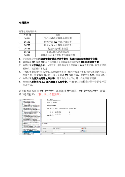
电调故障1)小区退服会导致;2)如果现场SBT或者RCU与天线接触不良或者设备故障会导致ALD电流异常告警3)如果出现运行数据异常,小区正常,那么检查下是否更换过RCU或者天线,配置数据需要修改,或者重启下电调4)一般配置数据时电调未校准,或者后期调整电下倾的时候没有校准电调导致电调天线未校准告警;如果数据都正常,那么是电调RCU故障导致,需要更换RCU,重新调配5)如果出现电调天线马达故障告警,建议首先复位下电调,仍是不行请更换6)如果出现射频单元ALD开关配置不匹配告警,一般可以后台检查下第一步供电开关打开方式:首先检查是否直连DSP RETPORT:;还是通过SBT相连,DSP ANTENNAPORT:;检查端口是否打开:(图、表、告警清单)案例:(通过SBT相连)MOD ANTENNAPORT: CN=0, SRN=64, SN=0, PN=R0A, PWRSWITCH=ON, THRESHOLDTYPE=UER_SELF_DEFINE, UOTHD=20, UCTHD=25, OOTHD=300,OCTHD=280;//修改天线端口(MOD ANTENNAPORTDSP ANTENNAPORT:;//查询天线端口动态信息(DSP ANTENNAPORTSCN ALD:;//扫描天线设备(SCN ALDADD RET: DEVICENO=1, CTRLCN=0, CTRLSRN=64, CTRLSN=0, RETTYPE=SINGLE_RET, SCENARIO=REGULAR, VENDORCODE="HW", SERIALNO="B5288710861385774";//增加电调天线(ADD RET)DLD RETCFGDATA: OPMODE=SUBUNIT, DEVICENO=1, SUBUNITNO=1,IP="192.168.0.48", USR="admin", SRCF="HA-ATR451714-1710-C(01).bin";//加载RET配置数据(DLD RETCFGDATALST RET:;//查询电调天线配置信息(LST RET)LST SECTOR:;//查询扇区配置信息(LST SECTOR)MOD RETSUBUNIT: DEVICENO=1, SUBUNITNO=1, CONNCN1=0, CONNSRN1=64, CONNSN1=0, CONNPN1=R0A, CONNCN2=0, CONNSRN2=64, CONNSN2=0,CONNPN2=R0B;//修改电调天线子单元(MOD RETSUBUNIT)CLB RET: OPMODE=SUBUNIT, DEVICENO=1, SUBUNITNO=1;//校准电调天线(CLB RET)DSP RETSUBUNIT: DEVICENO=1, SUBUNITNO=1;//查询电调天线子单元动态信息(DSP RETSUBUNIT)MOD RETTILT: RETCLASS=RET, OPMODE=DEVICENO, DEVICENO=1, TILT=30;//修改电调天线倾角(MOD RETTILT)DSP RETSUBUNIT:;//查询电调天线子单元动态信息(DSP RETSUBUNIT)DSP ALDVER: OPMODE=DEVICENO;//查询天线设备版本信息(DSP ALDVER)如果发生故障过,可以关闭重启端口试试,重新加载电调,如果出现硬件故障现场更换。
电调天线不能打开ALD电源供电开关

4) 自定义配置的电流门限问题导致电流保护。
解决步骤:
1) 检查组网情况,确保供电端口的唯一性和准确性;
2) 检查SBT/RCU/AISG电缆是否都已经安装好;
3) 检查自定义电流门限配置是否合理,主要是级联模式下RCU数量不同,电流门限不同;
4) 一般不能打开电源开关是SBT或者天馈系统串接了其他设备,首先检查天馈系统是否有其他隔直流设备,如开路避雷器等;
5) 检查天馈系统是否串接合路器,检查合路器的程完工,配置数据时,第一步打开ALD电源供电开关,发现无法打开,查询供电端口电流为0。
原因分析:
1) 不能打开ALD电源供电开关,一般是供电通道问题,如SBT、RCU、AISG电缆的硬件安装问题;
2) 明确组网是Antenna端口供电还是RET端口供电,供电打开方式命令不一样,且不能两个端口同时打开供电;
ALD电调天线配置指导

扫描RET天线
FA/D独立电调天线开通双模, 建议统一在LTE侧配置电调天线。
添加RET天线
设置RET天线下倾角
不正确
结束
HUAWEI TECHNOLOGIES CO., LTD.
Page 2
数据配置步骤
步骤1、执行MML配置ANTENNAPORT供电开关及电流 告警门限等参数。 MOD ANTENNAPORT 步骤2、执行MML扫描ALD设备。SCN ALD
10
10 10 10
15
15 15 15
300
400 500
280
360 440
200+ (100 x N)
200+ (80 x N)
表中数据是以华为TD-LTE基站和华为RET天线为例,按照2个RET天线级联组网形式配置。 此告警门限表适用于单个RET天线依次校准的场景。
HUAWEI TECHNOLOGIES CO., LTD.
ALD电调天线配置指导 (中国移动版本)
Version: V1.0(2013.11.16)
HUAWEI TECHNOLOGIES CO., LTD.
数据配置步骤
1. 执行MML配置ANTENNAPORT (RETPORT)供电开关及电流告警门限等参数 MOD ANTENNAPORT (8T8R RRU 和AAU3210适用此场景) MOD RETPORT (RRU3172-fad、RRU3250适用此场景)
2、四通道内置RCU电调天线序列号编码规则
天线端口上边频与颜色对应表
上边频范围 700 to 1000 MHz 1001 to 1700 MHz 1701 to 2300 MHz 2301 to 4000 MHz 字段含义 红色(r) 绿色(g) 蓝色(b) 黄色(y)
AAU3213智能天线配置指导书V2- 修改by Quanlang

AAU3213天线权值配置指导书
1 操作前核查
1、查询RRU型号:DSP BRDMFRINFO:CN=0,SRN=200,SN=0;
(注意查询框号为200的RRU型号,仅操作型号为AAU3213的基站)
2、查找删除权值:LST BFANT:; ////RMV BFANT:;
若查询出具有权值信息中天线类型为ATD451602、ATD4516C2这两种的1种,则需要使用RMV BEANT命令,删除所有的权值信息即可。
2 操作步骤
步骤1:打开ALD供电开关:MOD ANTENNAPORT:;
步骤2:查询ALD开关状态:DSP ANTENNAPORT:;
步骤3:扫描天线信息:SCN ALD:;
步骤4:添加RET设备:ADD RET
参数设置按照下表进行:
注:请在添加天线2~3分钟后设置天线下倾角。
(即步骤5)
步骤
5:修改内置电下倾:MOD RETSUBUNIT
步骤6:查询天线的实际下倾角:DSP RETSUBUNIT
命令查询天线的实际下倾角,验证实际下倾角与设置下倾角是否一致。
注:后续步骤为添加内置方位角的步骤
步骤7:添加RAE :ADD RAE
参数按照下表配置即可:
步骤8:检查RAE状态:DSP RAESUBUNIT
步骤9:修改RAE子单元:MOD RAESUBUNIT
步骤10:添加天线权值信息:ADD BFANT
步骤11:修改电子水平方位角:MOD BFANT。
Elecraft KXAT1 内部自动天线调节器设立指南和使用说明书
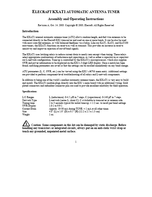
E LECRAFT KXAT1AUTOMATIC ANTENNA TUNERAssembly and Operating InstructionsRevision A, Oct. 14, 2003. Copyright © 2003, Elecraft; All Rights ReservedIntroductionThe KXAT1 internal automatic antenna tuner (ATU) allows random-length, end-fed wire antennas to be connected directly to the Elecraft KX1 transceiver and used on one or more bands. It can be also be used with most coax-fed antennas, or with balanced feedlines via a balun. Like our KAT1, KAT2, and KAT100 auto-tuners, the KXAT1 functions on receive as well as transmit. This provides an increase in receive sensitivity and improves rejection of out-of-band signals.The KXAT1 uses latching relays to reduce current drain to nearly zero except when tuning. These relays select appropriate combinations of inductance and capacitance, as well as either a capacitor-in or capacitor-out L-network configuration. Tune-up is controlled by the KXAT1's microprocessor, which also supplies SWR and power information to be displayed on the KX1's 3-digit LED display. Once a match has been found, matching parameters are saved so that the settings can be recalled immediately on any band change.ATU parameters (L, C, SWR, etc.) can be viewed using the KX1’s ATU menu entry. Additional settings are provided to perform component-level troubleshooting of all relays and L-network components.In addition to being one of the world’s smallest automatic antenna tuners, the KXAT1 is very easy to build and install. The KXAT1 module plugs directly into the KX1’s main board with no additional wiring. Gold plated connectors and redundant connector pins are used to provide excellent reliability for field operation.SpecificationsL/C Ranges L (inductance): 0-4.5 µH in 7 steps; C (capacitance): 0-140 pF in 7 steps Network Type L-network (series L, shunt C); C switchable to transceiver or antenna side Tuning time 1 to 3 seconds typical for initial tune-up; < 1/2 sec. to recall per-band settings SWR Display 1.0:1 to 9.9:1Current Drain Approx. 10-30 mA during TUNE; < 1 mA at all other timesSize 4.8" (L) x 1.0" (D) x 0.5" (H) (12.2 x 2.5 x 1.3 cm)Weight1 oz.Ca ution: Some components in this kit can be damaged by static discharge. Beforetouch any grounded, unpainted metal surface.12Parts InventoryThe table below lists all parts in the kit. The KX1 Owner's manual has photographs of similar parts.Ref.Description Qty Part No.C1Capacitor, 20 or 22 pF ("20," "22," "200," or "220")1E530017C2Capacitor, 39 pF ("39" or "390")1E530036C3Capacitor, 82 pF ("82" or "820")1E530038C4-C8,C11Capacitor, .01 µF ("103")6E530019C10Capacitor, 100 pF, 200 V, NPO disc ("101")1E530034C9Capacitor, 1-40 pF trimmer 1E540002D1,D2Diode, 1N57112E560004K1-K7Relay, DPDT 7E640010L1,2,3T37-2 toroid core, red, 0.37" diameter (L1=0.64 µH,12T; L2=1.3 µH, 17T; L3 = 2.6 µH, 25 T)3E680006P1Connector, 3 pin male, 0.1" spcg 1E620071P2Connector, 2 pin male, 0.1" spcg 1E620072P3Connector, 5 pin male, 0.1" spcg 1E620073R1,R2Potentiometer, 100 k trimmer, low-profile 2E520012R3Resistor, 200 ohms, 1/4-W, 5% (red-black-brown)1E500020R4Resistor, 3.3 k, 1/4-W, 5% (orange-orange-red)1E500017RFC1Miniature RF choke, 15 µH (brown-green-black)1E690012T1Transformer on FT37-43 core, 10 turns bifilar (see text)1E680003U1MCU, KXAT1, PIC16C7161E610016Z1Ceramic resonator, 4.0MHz +/- 0.2%1E660001MISCKXAT1 PC board (part of KX1 PC board set)1E100175MISCEnamel wire, #26 red 5 ft.E760002MISCEnamel wire, #26 green 2 ft.E760004MISCSolid, insulated hookup wire, green 1 ft.E760008MISCSocket for U1, 18 pins 1E620031MISC Foot, self-adhesive (spacer between ATU/bottom cover)1E700024Parts Placement DrawingsParts placement drawings for both sides of the KXAT1 PC board can be found in Appendix F of the KX1manual.3AssemblyA fine-point, temperature-controlled soldering iron (700-800 degrees F) is required to assembleminimum amount of solder to avoid ground shorts.All parts are installed on the top side of the board except as noted (the side with the relays, toroids,PC boards can be difficult.Place relays at locations K1-K7 as shown by their component outlines. Do not solder yet. Do notUsing a flat object to hold K1-K7 in place, flip the board over. Solder just one inner pin on each relay. Inspect the relays closely to make sure that they’re seated flat against the PC board. If not, re-heat theTrim the relay leads as short as possible to provide clearance for folded capacitors in a later step.Install the IC socket at U1. Align the socket's notched end with the notch in the component outline.On the bottom side, install R3 (200 ohms, red-black-brown) and R4 (3.3 k, orange-orange-red).Install D1 and D2, with the banded end of each diode oriented as shown on the board.Install ceramic resonator Z1, which looks like a capacitor with three leads. It can be installed in eitheralter its frequency. Trim the leads after soldering.Install trimmers R1 and R2 on the bottom side. Make sure they are seated flat against the PC board.Install RF choke RFC1 (brown-green-black). The leads are fragile—handle carefully.Install the trimmer capacitor, C9, on the bottom side. The flat side should be oriented as shown by theInstall the capacitors listed below on the bottom side of the board, but don't solder them yet. Leave the shown in parentheses.__ C1, 20 or 22 pF (20, 22, 200, or 220)__ C2, 39 pF (39 or 390)__C3, 82 pF (82 or 820) __ C10, 100 pF (101)4Fold down C1, C2, and C3 at about a 45-degree angle, but not so far that they contact the nearby relaySolder C1-C3 and C10 from the bottom side to avoid damaging the relays. Trim the leads on the top. In the following step, the installed height of the capacitors must be no more than 5/16" (7.5 mm).installed height is below the limit specified, there's no need to straighten the leads.Install the .01-µF capacitors ("103") on the top side of the board (C6, C4, C5, C7, C8, C11). TheyIn the following steps, inductors L1 through L3 will be wound and installed. There is no need toInductor L1 is wound on a T37-2 core (red) using 8" (20 cm) of #26 red enamel wire. To wind the inductor, pass the long end of the wire through the core exactly 12 times . Each pass through the corecounts as one turn. The finished winding should look like the illustration below. Exact turns spacing is not critical.Remove insulationSpread out the turns of L1 so they occupy about 80-90% of the core’s circumference.Cut L1's leads to about 1/2" (12 mm) long. Completely remove the enamel insulation from the leads to within 1/8” (3 mm) of the core. The enamel wire provided can be heat-stripped using a small amount of solder on the tip of your iron. Stripping using this method takes 4-6 seconds.5Install L1 vertically on the PC board as shown by its component outline, then pull the leads taut onTrim and solder the leads of L1. When soldering, make sure that the solder binds well to the leads. IfMeasure from pad to pad using an ohmmeter to verify the connection (low resistance).Wind and install L2 and L3 using the same procedure you used for L1. The number of turns and wire __ L2, 17 turns (11" [28 cm])__ L3, 25 turns (15" [38 cm])Fold C10 down toward K6 and L3, but not so far that it touches the leads of these components.T1 is wound on a ferrite toroidal core (gray, FT37-43; may have an orange dot). Cut two 10" (25 cm)coating is not chipped or broken.Twist the two wires together, crossing over each other about 3 to 4 times per inch (1-2 times per cm). Wind the twisted wires onto the core as shown below, using 10 turns. Each pass through the coreAs shown below, the wires labeled (1) and (3) should originate from below the core, andabove it. This will ensure that the transformer has the correct phasing.Trim the leads of T1 to about 1/2" (12 mm) long. Then completely remove the insulation from T1's an X-acto knife. Do not attempt to burn off the insulation using a match or lighter, as the flame may fuse the pairs of wire together, causing them to become shorted.6Tin T1's leads with solder. If the leads do not tin easily, the insulation may not be fully removed.Using an ohmmeter, measure between the red and green wires to make sure that they're not shorted. Install T1 as indicated by its PC board outline. Insert the leads into the numbered holes as identifiedPull the leads taut on the bottom of the board. Before soldering, make sure that the entire portion ofCut a 1-1/8" (2.9 cm) length of insulated, solid-conductor hookup wire. Remove 1/4" (6 mm) ofInsert this wire through the center of T1 and into the pad labeled 5. Bend the wire down to the left and 6. Pull the leads of the wire taut on the bottom of the board, then solder.Install the self-adhesive foot in the location identified on the ATU module ("FOOT").Touch a grounded, unpainted metal surface before handling the microcontroller (U1, 16C716).the pin 1 label.Remove the bottom cover from the KX1 transceiver (2 thumbscrews) and turn it upside-down withRemove the jumper installed between pins 1 and 3 of J7 (ATU bypass).The KXAT1 kit includes mating male connectors for J8, J7, and J6, designated P2, P1, and P3,connectors on the KX1 board. P1-P3 must be fully seated, or the bottom cover will not fit properly withthe ATU installed.Place the KXAT1 module onto the pins of P1-P3. Verify that the module is resting flat against thethe positions of toroids and capacitors on the two boards to allow them to fit together without obstruction.Press down on the KXAT1 at both ends to ensure that P1-P3 are fully inserted into J6-J8. Then solderall pins of P1-P3.Trimmer R4 on the KX1 board is accessible through a hole in the ATU board (as well as aclockwise (maximum power output, about 4 watts at 12-13V). R4 can be adjusted using a small flat-blade screwdriver.This completes KXAT1 assembly. Keep the bottom cover off for the alignment and test steps which follow.7Alignment and TestConnect a power supply or battery to the KX1 and turn on power. Tap MENU and scroll through the entries until you find ATU . To select the mode for the ATU, hold . If you see three dashes (---) instead of the ATU parameter, refer to Troubleshooting.Using the VFO knob, set the ATU parameter to the first relay test setting, L0. You should hear a L1, then to L2, and finally to L3. The same should be true for C0through C3, as well as N1 and N2. (If you don't hear any relays switching, see Troubleshooting.) Exit themenu.Select 40 meters using the KX1's BANDswitch.Connect a 50-ohm dummy load to the KX1’s antenna jack (5W or higher rating).Set the ATUparameter to CALusing the menu. Pre-set potentiometers R1 and R2 on the bottom of the ATU board to exactly their mid-points.Touch the (+) lead of a digital multimeter (DMM) or analog voltmeter to the small hole near the" label on the bottom of the KXAT1 board. Connect the (-) lead to one of the KX1's long standoffs.Set the voltmeter for 2 or 3 DC volts full scale. Locate a non-metallic tuning tool for adjusting ceramic trimmer C9. You can use a small flat-blade Enter TUNE mode by holding M ENU and BAND together (the KX1 will display forward power,). Adjust C9 for the lowest possible voltmeter reading—the null may be sharp. Cancel TUNE mode by tapping any switch (the KX1 will display SWR, e.g. r1.0).If your voltmeter has a lower scale than 2 or 3 V, set it for this scale, and repeat the previous step.Optional Power Calibration: The KXAT1 will provide acceptable power-reading accuracy with R1 andR2 set to exactly their mid-points. More accurate adjustment requires a calibrated wattmeter:Connect a known-accurate wattmeter between the KX1 and a 50-ohm dummy load.Enter TUNE mode. Adjust R1 (FWD) on the KXAT1 so that the KX1’s power display agrees with the r1.0. If it doesn't, chances are your dummy load is not 50 ohms, or the null adjustment (C9) was not done correctly.Adjust R2’s rotation to match that of R1 (visually).Installing the Bottom CoverTurn off the KX1 and re-install the bottom cover. Be very careful not to pinch the battery wiresUsing The ATUBasic ATU Operation• Connect the best possible antenna and ground to the KX1 (see Antenna Considerations).• Use the KX1 menu to set the ATU’s operating mode to TUN (auto-tune), then exit the menu.• Enter TUNE mode (M ENU + B AND). ATU will be displayed for a few seconds while the tunerfinds the best match (if you don't hear any relays, the SWR was already low). Power will thenbe displayed (e.g. P4.0). Tap any switch to cancel TUNE; the SWR will be displayed (e.g. r1.0).• With the ATU installed, the LED bargraph will show power output while keying (0.5 watts per bar).• ATU settings are stored in EEPROM, and will be recalled instantly whenever you change bands. Displaying Power Output and SWR while preserving matched L and C settingsIf you change the ATU setting to rX.X (SWR) in the menu, L and C settings will not be changed during TUNE mode, even if the SWR is high. This setting is rarely needed; TUN mode is recommended.Using an External Antenna TunerIf you're using an external antenna tuner, bypass the KXAT1 by setting ATU to CAL. Power and SWR will still be displayed in TUNE mode. Note: The KXAT1 cannot display SWR continuously during TUNE, so an external tuner with built-in SWR bridge is recommended. Most stand-alone tuners include a bridge. Important ATU Operating Tips• A 1.0:1 SWR is not necessary for good performance. However, a low SWR will help protectthe transmitter. See Antenna Considerations.• If you switch to BAT (battery) display mode, then enter TUNE, you'll see the transmit-mode batteryvoltage, not SWR or power output. The ATU settings will not change. If the indicated battery voltagedrops too far on transmit, the battery should be recharged or replaced.ATU Menu SettingsTable 1 lists all of the ATU menu settings. TUN is used for normal operation, and the tuner is bypassed when set to CAL. Other settings are primarily used for troubleshooting.Table 1. ATU ModesMode Description Mode DescriptionCAL Calibration/Bypass, L and C = 0Exx1-49 = error (see Troubleshooting)TUN Auto-tune mode Fx.x KXAT1 firmware revision, e.g. F1.0rx.x SWR from most recent TUNE L0-L3Individual inductor test (C = 0)Lx.x Inductance, µH C0-C3Individual capacitor test (L = 1 µH)C.xx Capacitance, nF (.01 nF = 10 pF)N1Network relay test, Cin (L/C = 0)NTx Network type; 1=Cin, 2=Cout N2Network relay test, Cout (L/C = 0)8Antenna ConsiderationsThe KXAT1 will work with coax-fed dipoles, verticals, etc., but it's optimized for use with random-length wire antennas. These are often the easiest antennas to set up in the field. However, certain wire lengths must be avoided, and ground radials are required (both issues are discussed below). You should test your chosen antenna system ahead of time, if possible, to be sure the KXAT1 can achieve an acceptable match. No-feedline operation: At QRP power levels, feedline is not always necessary. In many cases you can connect a wire antenna directly to the KX1 and toss it into a tree, then lay out at least one ground radial, as shown below. This antenna can be set up quickly, and compares favorably to a low, coax-fed dipole or inverted V. It also minimizes station weight (see further details on wire and accessories on page 10). If you toss the wire into a tree, try to keep all but about one foot of wire exposed. A wire that is mostly in a tree will still radiate, but not as well.Wire antenna length: Since the KX1 can only match a moderate range of impedances, a given random wire length is not guaranteed to provide an acceptable match on all three bands. Results will vary depending on the wire length, height, type of support, and ground system. But for backpacking use on40/30/20 meters, a wire length of 24-28 feet will generally provide good results. For use on 30/20 m only, as little as 12 ft. can be used, and for 20 m only, as little as 8 ft. Avoid lengths which are close to a half-wavelength long or any multiple thereof, which will be out of the KXAT1's matching range. For example, you should avoid using close to 33' if 20 m operation is planned, or 46' if you'll be using 30 m.Ground system: Use a at least one ground radial, cut to at least 1/8th wavelength on the lowest band used (16' on 40 meters). When possible, use two or more radials, with one cut to 1/4 wavelength on each band.9Backpacking Verticals: The KXAT1 may improve the match to a backpacking-style vertical. If the antenna has a loading coil, you should first adjust it for minimum SWR, since such antennas can be very narrow-banded. Set the ATU menu entry to CAL mode (bypass) for this purpose, then back to TUN mode to further match the antenna using the KXAT1 (if necessary).Whip Antennas: Short whip antennas connected directly to the KX1 may damage the antenna jack or PC board, and so should only be used in an emergency. They are also very poor radiators.Do I Need a really low SWR? Not necessarily. For example, if the SWR is 2:1, the loss in transmitted signal strength will be only about 0.5 dB. However, a low SWR will protect the transmitter, and an SWR under 2:1 is recommended. The KXAT1 always tries to hit 1:1, and with most antennas it will find an SWR below 1.5:1 on most bands. If the SWR is higher than 2:1 after matching, try using a balun or reconfiguring the antenna or changing its length.Using Baluns:A balun can improve the match to very high-impedance antennas, allow the KXAT1 to be used with balanced line, and help isolate the antenna from the rig to reduce RF pickup. A low-loss, broad-band, 4:1 balun such as the Elecraft BL1 is a good choice(it's also quite small—just 1.5 x 3"). Suggested Wire and AccessoriesWire: #26 stranded copperclad steel wire, such as Wireman #541 (also available from Davis RF as#WM541), is strong, lightweight, and easy to keep straight. A 25-ft. length weighs less than half an ounce. Adapters: To go from BNC directly to wires, you'll need an adapter. The smallest suitable adapter is the Pomona model 3430-2, which is a singlebinding post to BNC male (see drawing below).If you use this adapter type, you'll need to use one of the KX1's thumbscrews as a ground tie-point, requiring that you carefully remove some paint from around the bottom cover holes on both inside and outside. A larger but more versatile adapter is the Pomona model 1296. This is a double binding post to BNC male, which provides both antenna and ground connections. The more expensive model 3296 also has double binding posts, but they're the miniature type, reducing overall dimensions.Weights: A large, stainless steel hex machine nut, thread diameter 5/8", can be found at hardware stores and works well for tossing wires into trees (weight: about 1 oz.). If you prefer fishing weights, avoid using lead, which is toxic to wildlife. Stainless steel weights are available (e.g., 1). Supporting hardware: End insulators and non-conductive support line are not strictly necessary for low-power portable antenna installations. In general, you can simply attach a weight to the end of the wire itself. But if you prefer to isolate the end of the wire to minimize interaction with other objects, you can fabricate lightweight insulators from small pieces of plastic. Small-diameter nylon cord can be used for support lines. 1Additional suppliers can be found with a web search for "non-toxic weights" or "non-toxic fishing tackle."10TroubleshootingIf the ATU menu parameter shows "---" at all times, look for a connector shifted by one position, an unsoldered pin, U1 installed backwards on the ATU board, or a defective U1. Also check the ATU PC board for shorts to ground, solder bridges, and unsolderedIf the ATU menu parameter becomes "---" after doing a tune-up, it may be due to very high RF feedback into the transceiver. Turn power off and back on, then re-test the ATU using a dummy load or a different antenna. If it functions correctly on a dummy load but not on your antenna, try using a balun.If the SWR isn’t < r1.2 with a 50-ohm load, C9's setting may be incorrect.If the power indicated is always about 0 watts, the windings of T1 may be reversed, or one or more leads of T1 or L1-L4 may not be properly stripped.If the ATU shows an error message (Exx in the menu where xx is between 1 and 49), you may have a defective microcontroller (KXAT1-U1). Exx numbers 50-99 are used for tune-up algorithm tracking, and do not indicate a problem.If SWR is not displayed after exiting TUNE, you may have high RF feedback into the transceiver. You may need to improve your ground system, move the antenna farther away, or use a balun.If the tuner is unable to achieve a low SWR on some bands, even with several different antennas, you could have a single defective relay or component on the L-C board. Start by slowly scrolling through ATU menu parameters L0 through L3, C0 through C3, N1, and N2. These are intended for relay testing. For example, L0 turns off all of the inductor relays (K4-K6). L1 turns on K4, etc. Similarly, C0 turns off all of the capacitor relays, and C1 turns on K1. N1 and N2 place the network configuration relay, K7, into its two positions: CTX (C-in L-network) or CANT (C-out L-network).If the relays are all working but you suspect an inductor or capacitor, you can test each L and C by noting their effect on SWR, one at a time. Start on the highest band. Connect a 50-ohm dummy load to one of the antenna jacks, select L0, do TUNE, and note the SWR reading. Then select L1 and do TUNE again; the SWR should change by a small amount. L2 should have a larger effect, etc. If the inductance selections cause the SWR to go off the scale (9.9), switch to a lower band, go back to L0, then test the remaining inductors. Similarly, you can test all three capacitors, starting on the highest band with C0, C1, etc. You'll know you have found the bad component if it has too large or small an effect (or no effect) on SWR, in relation to the others tested.11Circuit DetailsThe ATU uses three inductors and three capacitors in an L-network, with values optimized for use with moderate-length wire antennas on 40-20 meters. The capacitance can be placed at the transmitter or antenna end of the network via K7. Each inductor and capacitor has its own DPDT relay, with the individual sections of each relay placed in parallel for reliability. The relays are selected under control of the ATU's microcontroller, U1. Latching relays are used so that they will not consume any power except when the operator is actually tuning.T1, D1, D2 (etc.) form a directional coupler for SWR and power measurements. The bridge output is buffered by op-amp U2 and routed to the KX1 control board. The bridge outputs are also connected to A-to-D inputs on the microcontroller, U1. U1 measures these voltages and converts them to SWR or power readings, using averaging and linearization techniques to improve accuracy. During transmit, the VFWD line provides an analog power indication to the KX1’s main microcontroller. At other times this line used to transmit digital data between the ATU and KX1. U1 "sleeps" except during antenna tune-up, so it generates no receiver noise.KXAT1 SchematicElecraft • • 831-662-8345。
- 1、下载文档前请自行甄别文档内容的完整性,平台不提供额外的编辑、内容补充、找答案等附加服务。
- 2、"仅部分预览"的文档,不可在线预览部分如存在完整性等问题,可反馈申请退款(可完整预览的文档不适用该条件!)。
- 3、如文档侵犯您的权益,请联系客服反馈,我们会尽快为您处理(人工客服工作时间:9:00-18:30)。
Page 4
数据配置步骤
步骤5、设置RET天线下倾角。 MOD RETSUBUNIT 步骤6、查询RET 天线下倾角。 DSP RETSUBUNIT
由于不同厂商、不同型号的电调天线所支持的范围可能不同。在设置前,建议 通过DSP RETDEVICEDATA命令查询需要设置的RET所支持的倾角范围。
正确
扫描RET天线
FA/D独立电调天线开通双模, 建议统一在LTE侧配置电调天线。
添加RET天线
设置RET天线下倾角
不正确
结束
HUAWEI TECHNOLOGIES CO., LTD.
Page 2
数据配置步骤
步骤1、执行MML配置ANTENNAPORT供电开关及电流 告警门限等参数。 MOD ANTENNAPORT 步骤2、执行MML扫描ALD设备。SCN ALD
10
10 10 10
15
15 15 15
300
400 500
280
360 440
200+ (100 x N)
200+ (80 x N)
表中数据是以华为TD-LTE基站和华为RET天线为例,按照2个RET天线级联组网形式配置。 此告警门限表适用于单个RET天线依次校准的场景。
HUAWEI TECHNOLOGIES CO., LTD.
HUAWEI TECHNOLOGIES CO., LTD.
Page 7
附录二 TD-LTE基站RET天线电流告警门限
欠流告警产 生门限(mA) 欠流告警消 失门限(mA) 过流告警产 生门限(mA) 过流告警消 失门限(mA)
ALD系统个RET天线级联 CUSTOM 3个RET天线级联 N个RET天线级联 1. 2.
HUAWEI TECHNOLOGIES CO., LTD.
Page 5
附录一 RET天线序列号编码规则
1、FA/D独立电调天线序列号编码规则
天线背板序列号规则
字段位数 1~2 3 4~7 8 9 10~13 14~18 19 字段含义 厂家编码 设备类型 天线ITEM码 出厂年份 出厂月份 流水号 随机码 Color Coding码 字段说明 固定为“HW”。 “M”表示RET电调设备,“X”表示RAE权值管理设备。 对应天线的ITEM码后4位。例如:ITEM码是“27011175”,取后4位即为“1175”。 用0~9表示2000~2009年,用26个大写字母表示2010年及后续年份。 例如:2004年用“4”表示,2013年用“D”表示。 采用16进制。例如:“1”表示1月,“A”表示10月。 设备生产时产生的流水号。 设备生产时产生的随机码。 “b”表示FA频段,“y”表示D频段。
一个RET天线有两组 序列号,分别存储 于天线背板和AIMM 中。当基站扫描天 线时,AIMM首先检 测背板工作状态, 若背板正常,则优 先上报存储于天线 背板中的序列号, 若背板故障,则上 报AIMM自身存储的 序列号。
HUAWEI TECHNOLOGIES CO., LTD.
Page 6
附录一 RET天线序列号编码规则
ALD电调天线配置指导 (中国移动版本)
Version: V1.0(2013.11.16)
HUAWEI TECHNOLOGIES CO., LTD.
数据配置步骤
1. 执行MML配置ANTENNAPORT (RETPORT)供电开关及电流告警门限等参数 MOD ANTENNAPORT (8T8R RRU 和AAU3210适用此场景) MOD RETPORT (RRU3172-fad、RRU3250适用此场景)
1710 - 2180 频段的左侧 端口对应的内置RCU 的序列号:
HWM0994D132653698yL
1710 - 2180 频段的右侧 端口对应的内置RCU 的序列号:
HWM0994D17824167yyR
第1 位、第2 位:表示厂家编码,固定为“HW”。 第3 位:表示是内置RCU,固定为“M”。 第14 位~第19 位用:“yL”黄色,左侧天线。“yyR”第二个黄色,右 侧天线。
独立电调天线扫描结果为2个天线,FA与D部分有各自独立序列号。 请参考附录一中如何通过序列号区分FA与D频段天线。
扫描天线等待时间 较长,请耐心等待
HUAWEI TECHNOLOGIES CO., LTD.
Page 3
数据配置步骤
步骤3、执行MML配置RET及其参数。 ADD RET 步骤4、执行MML校准RET。 CLB RET
Page 8
谢谢!
Copyright © Huawei Technologies Co., Ltd. 2012. All rights reserved. No part of this document may be reproduced or transmitted in any form or by any means without prior written consent of Huawei Technologies Co., Ltd. NO WARRANTY The information in this document may contain predictive statements including, without limitation, statements regarding the future financial and operating results, future product portfolio, new technology, etc. There are a number of factors that could cause actual results and developments to differ materially from those expressed or implied in the predictive statements. Therefore, such information is provided for reference purpose only and constitutes neither an offer nor an acceptance. Huawei may change the information at any time without notice.
天线配置流程
开始
配置准备
打开RET天线供电开关
不正确
2. 执行MML扫描ALD设备。
SCN ALD 3. 执行MML配置RET及其参数 ADD RET 4. 执行MML校准RET CLB RET 5. 执行MML配置RET倾角 MOD RETSUBUNIT
查询RET天线 下倾角
正确
查询RET天线 供电状态
校准天线等待时间 较长,请耐心等待 1)通过天线扫描结果配置RET天线信息,常规安装场景下,控制端为 连接RRU的R0A端口或是RET端口。 2)天线设备名称用户可以自定义,要保证名称一个基站内不重复,否 则系统会返回重名。 3) 中国区使用独立电调天线均为单天线。 4)天线场景参数的选择需要与物理实际连接场景一致,否则系统无法 与RET天线正常通信。TD-LTE基站 RET天线配置时,请选择“级联安装 场景”。 5)独立电调天线如果只接D频段使用,只需增加D频段部分。如果接 了FA部分,需要增加两次天线。如果TDS不能电调,需要将两个天线都 绑定到D频段LTE RRU上。
AIMM序列号规则
字段位数 1~2 3 4~12 13~14 15 16~18 19 字段含义 厂家编码 设备类型 随机码 出厂年份 出厂月份 流水号 位置信息 字段说明 固定为“HW”。 “B”表示RET电调设备,“X”表示RAE权值管理设备。 设备生产时产生的随机码。 取年份后两位数字表示2000~2099。例如:“13”表示2013年。 采用16进制。例如:“1”表示1月,“A”表示10月。 设备生产时产生的流水号。 表示AIMM位置信息,“1”表示AIMM左边电机,控制FA频段;“2”表示AIMM右边电 机,控制D频段。
2、四通道内置RCU电调天线序列号编码规则
天线端口上边频与颜色对应表
上边频范围 700 to 1000 MHz 1001 to 1700 MHz 1701 to 2300 MHz 2301 to 4000 MHz 字段含义 红色(r) 绿色(g) 蓝色(b) 黄色(y)
天线阵列位置对照表
天线阵列垂直方向分布 缩写 T M B 含义 顶部天线阵列 中部天线阵列 底部天线阵列 天线阵列水平方向分布 缩写 L C R 含义 左侧天线阵列 中心天线阵列 右侧天线阵列
•说明: • 柜号、框号、槽号、端口号根据使用的主设备配置情况来填写。 • 在操作过程中,由于RET天线校准过程中电流会增大,因此电流告警门限类 型推荐使用“UER_SELF_DEFINE(用户自定义类型)”,根据实际使用RET天线 级数手动设置电流告警门限,避免选择其余自动设置类型导致校准时基站过流 保护。电流告警门限请根据附录二的电流告警门限配置中推荐值设置。 • RRU/RFU的天线端口和“RET”端口的供电开关不能同时设置为“ON”,否 则系统返回“执行失败”。