TBT8855中文资料
885电气系统技术规格书
SJ017/885-2008 885电气系统技术规格书编制:蔡熙明 2008.5.19 校对:梁帆 2008.5.21审批:梁晓东 2008.5.22根据项目设计总体要求,YC225LC-8(885)电控系统具有以下功能:1、采用16键彩色显示器、MC中型控制器、油门步进电机等组成了挖掘机功率控制系统。
2、根据发动机的负荷的变化,自动调节液压泵吸收的功率,这样,既充分利用发动机的功率,又防止发动机过载熄火。
3、机器具有自动功率模式:H模式(重挖掘动力模式),S模式(节能模式),L(轻载模式)和手动功率模式。
4、具有瞬间增力功能,具有自动怠速控制功能,附件装置控制功能。
5、配置GPS系统,使机器具有定位功能和远程监控功能。
电气系统的组成,可详见885-13电气系统图纸。
本技术规格书,主要包含以下内容:1、彩色显示的监控画面介绍和显示器操作方法。
2、机器的启动、运行、停车、功率控制选择等操作方法。
3、发动机油门系统调整方法。
4、电气系统安装调试的主要技术参数,和检验方法。
1.彩色显示器操作说明本机的监控显示采用“T0412-03235 显示器”。
1.1.彩色显示器面板布局介绍彩色显示器面板(中文界面)布局如图(Fig.1.01)所示。
工作时间计时和时钟(机器状态显示(Fig.1.03)主画面(Fig.1.05)通过按键进行操作菜单的操作,在监控器的主显示区将有不同的信息显示。
注:1、“附件控制”只对应于配装有特定的附件装置有效。
2、“工作模式选择”因各机器的配置不同,控制效果也有差别。
1.3.监控器的操作开启电源,显示器启动后自动进入监控主界面,如图所示(Fig.1.07)。
显示界面显示当前机器的状态信息,(发动机未启动时,有电池电压偏低的报警,有机油压力低报警。
发动机正常启动后,电源电压报警和机油压力低报警标志将消失。
)1.3.1.监控器主菜单:,进入屏幕“主菜单”(Fig.13.08)按或在进行系统初始化设置、数据检查、调试等的操作,将在《机器的调试、检验项目说明》中描述。
Model 8850-1高功率扫描生成器商品说明书

s Automatic leveling of output voltage as frequency is scanned or swept.
output terminals to provide up to 2 KV into 20,000 ohm load, 3 KHz to 30 KHz.
or sweeping mode for four frequency bands
this arrangement, the unit maintains a constant injection level (up to a maximum of 7.5 volts r.m.s.) as frequency is scanned or swept.
Maximum power output of the unit into a 1.5 ohm resistive load is over 300 watts and 200 watts into 2.5 ohms. The output voltage into a 0.5 ohm load connected to the secondary of the associated Type 6220-1A Transformer can be adjusted to a level in excess of ten volts at 1.0 KHz.
When used in conjunction with the Type 7021-1 Phase Shift Network and the Type 6220-1A Transformer, provision is made for sensing the audio voltage being injected into the EUT and displaying it on the digital panel meter. In
TBT8854中文资料
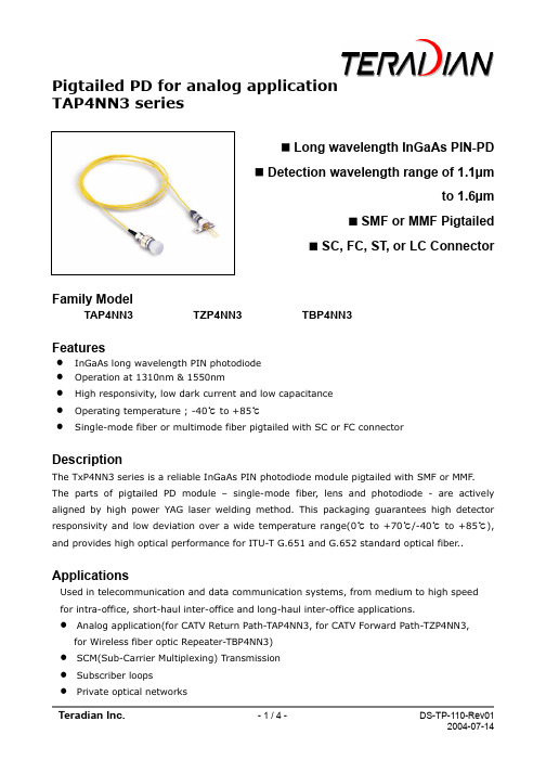
Pigtailed PD for analog applicationTAP4NN3 seriesLong wavelength InGaAs PIN-PDDetection wavelength range of 1.1µmto 1.6µmSMF or MMF PigtailedSC, FC, ST, or LC ConnectorFamily ModelTAP4NN3 TZP4NN3 TBP4NN3FeaturesInGaAs long wavelength PIN photodiodeOperation at 1310nm & 1550nmHigh responsivity, low dark current and low capacitanceOperating temperature ; -40℃ to +85℃Single-mode fiber or multimode fiber pigtailed with SC or FC connectorDescriptionThe TxP4NN3 series is a reliable InGaAs PIN photodiode module pigtailed with SMF or MMF. The parts of pigtailed PD module – single-mode fiber, lens and photodiode - are actively aligned by high power YAG laser welding method. This packaging guarantees high detector responsivity and low deviation over a wide temperature range(0℃ to +70℃/-40℃ to +85℃), and provides high optical performance for ITU-T G.651 and G.652 standard optical fiber.. ApplicationsUsed in telecommunication and data communication systems, from medium to high speedfor intra-office, short-haul inter-office and long-haul inter-office applications.Analog application(for CATV Return Path-TAP4NN3, for CATV Forward Path-TZP4NN3, for Wireless fiber optic Repeater-TBP4NN3)SCM(Sub-Carrier Multiplexing) TransmissionSubscriber loopsPrivate optical networksAbsolute Maximum RatingsParametersSymbol Unit Min.Max.RemarksAmbient Operating Temperature T op ℃ -40 85 Outdoor use Storage Temperature T stg℃-40 85Reverse Voltage V RP V - 15/20/ Reverse Current I RP mA - 3/1 / Forward CurrentI FL mA - 50/2/ Lead Soldering Temp./Time℃/sec260/10Electrical & Optical Characteristics (T op = 25℃) ParametersSymbol Condition Unit Min.Typ.Max.RemarkDetection rangeλV R =5V , R>0.75R > 0.65µm1.1 1.6Responsivity R V R =5V ,λ=1.3µm V R =5V , λ=1.5µm A/W0.800.85 0.85 0.90Dark Current I DV R =5V nA 1.0Cut-off Frequency f c -3dB, V R =5V GHz 2/3R L =50ΩReverse Breakdown VoltageV BDV R =5V , I RD =1µAV 25/0 Capacitance C V R =5V , f=1MHzpF0.6Second-Order DistortionIMD2V R =12V ,P AVG =0dBm, OMI=0.4, Note1dBc-70TAP4NN31)TZP4NN32) TBP4NN33)Third-Order Distortion IMD3 Note 1dBc -75 TZP4NN32) TBP4NN33)Back Reflection IL dB -45 Active Area Diameter∅µm75/70 45for 2GHzfor 5GHzNote1-1) TAP4NN3 : Two-tone test condition : f1=13MHz, f2=19MHz, f1±f2Note1-2) TZP4NN3 : Two-tone test condition : f1=320MHz, f2=450MHz, f1±f2, λ=1550nm per channel Note1-3) TBP4NN3 : same as the Note1-2! Handling CautionThe Photo-diode can be damaged by overvoltage and current surges. Precautions should be taken for transient power supply.This device is susceptible to damage as a result of electrostatic discharge(ESD). Take proper precautions during both handling and testingBottom view2Pin DescriptionPin No. Symbol Description 1A PDPD anode2 K PD PD cathode3 GND CasegroundOutline Diagram- TAP4xx3-xxxH-- TAP4xx3-xxxNFig.4 Pigtailed PD Package Dimensions [unit: mm]Ordering Information- 220m with 62.5/125µm MMF @1.25Gbps - 500m with 50/125µm MMF @1.25Gbps - 200m with 62.5/125µm MMF @2.125Gbps *Note 2 ; additional order information- Connector type default is SC/PC and the default length of fiber is 1mMore InformationTeradian Inc.Address 946, Dunsan-dong, Seo-gu, Daejeon, 302-120, Korea Tel +82-42-476-4800, 4803(Oversea Sales Team) Fax +82-42-476-4805Homepage e-mail sales@Com panyDevice TypeWave-length Data rate (PIN-TIA)Volt. (TIA)PinTemp. Range FiberConne ctor FlangeT A P 4N N 3 -I S NHTera dian A ;PD for CATV Return pathZ ;PD for CATV Forward Path B ;PD forwireless repeaterP ;PIN T ;PIN-TIAA ;APD 4;1.3/1.5 8;850nmN ; None0; 51Mbps 1;155Mbps 4;622Mbps 8;1.25Gbps G ;2.5GbpsN ; None 3;3.3V 5;5V 3;3pin 4;4pin (diffe- rential) 5;5pin 6;4pin (single ended)I ;Indoor Use(0~70℃) O ;Outdoor Use(-40~85℃)S ;SMFM ;MMF N ;None S ;SC F ;FC T ;ST L ;LCN ; None V ;Vertical H ; Hori- zontal。
ICP DAS PROFI-8855 产品快速启动用户指南说明书

Quick Start User Guide●IntroductionThis user guide introduces the user how to implement the PROFI-8855 into their applications in a quick and easy way. Therefore, it only provides the basic instructions. For more detail information about the PROFI-8855, please refer to the PROFI-8855 user manual in the ICP DAS product CD or download it from ICP DAS web site.●P ROFI-8855 Hardware Structure●PROFI-8855 Connector and Pin AssignmentPin No. Signal Meaning3 B-Line Receive/Transmit data – plus5 GND Power ground of active terminator6 VP Power 5 volt of active terminator8 A-Line Receive/Transmit data - minus The PROFIBUS connector is a standard 9-pin D-Sub connector, there are only 4 pins used in PROFI-8855. The pins VP and GND support the 5 volt power to active terminal resistor, and the A-Line and B-Line is the data bus.●Status IndicatorPROFI-8855 provide three types of status indicators, they are PWR LED (yellow), ERR LED (red) and RUN LED (green).Status Indicator Meaning Recommend solutionERR ON &RUN OFFPROFI-8855 is offlinewith no valid baud rate(offline mode*)Check the address setting ofPROFI-8855 and DP-master.ERR Flash(0.1 Sec)PROFI-8855 detectsbaud rate, but is stilloffline.(stop mode*)Check the DP-Master isready to communicate withPROFI-8855.ERR Flash(0.5 Sec)PROFI-8855 Prm isFault.(Note 1)Check the setting ofPROFI-8855 in the masterinterface and make sure ofthe consistency.ERR Flash(1 Sec)PROFI-8855’s Cfg isfault(Note 2)Same as aboveERR ON & RUNONPROFI-8855 is in clearmode*.Sets the DP-Master fromclear mode to operationmodeERR OFF & RUNONPROFI-8855 is inoperation mode*.PWR & ERR Flash(1 Sec)PROFI-8855 detectmodule(s) offlineFind the reason of the fault ofcorresponding module.●Terminating ResistorsIn order to minimize the reflection effect of the signal transmission, PROFIBUS device has to fit with an active terminal resistor at both first node and last node. The connection of active terminating resistors is shown in above circuit diagram. The PROFI-8855 doesn’t have any terminatingresistors inside. Therefore, users must add the terminator in external. In general, PROFIBUS connector has terminating resistors inside, and there is a switch to control the ON/OFF of the terminating resistors, as shown below.PROFIBUS ConnectionThe PROFIBUS interface of the PROFI-8855 is a DB9 female connector. It is recommended to use a standard PROFIBUS cable and connector (DB9 male).NOTE: Both side of the PROFIBUS cable which connect PROFI-8855 can add a core to reduce noise.Node AddressThe figure shown above is the hexadecimal rotary switch. It dominates the node (station) address of PROFI-8855. The switch which labeled MSB is high nibble of address and the other one is low nibble of address.According to PROFIBUS specification, the station address which from 0 to 126 is valid, and the address 126 is a special address that supports the remote setting SSA telegram from Class 2 DP-Master. PROFI-8855 uses the value of rotary switch as its address if the address is valid. While the address is invalid, PROFI-8855 will load the pre-saved value in EEPROM. Moreover, if the address is invalid (126) again, PROFI-8855 awaits the SSA telegram and applies it. (Note: If you want to clear the setting stored in EEPROM, you should adjust rotary switch to FF before the power is supplied).Rotary Switch(dec) Pre-saved address (EEPROM) SSA Telegram PROFI-8855Station Address0~125 Don’t care No Accept Rotary Switch 0~125 No Accept Pre-saved address(EEPROM)126 (default) Accept with address 0~125 SSA Telegram andsave address toEEPROM126~254 127~254 impossible N/A255 Clear to 126 Accept with address0~125SSA Telegram andsave address to EEPROMEX 1 : MSB => 0, LSB => B,node address of PROFI-8855 => (0*16+11) = 11EX 2 : MSB =>7, LSB => 9,node address of PROFI-8855 => (7*16+9) = 121PROFI-8855 – Setting and Module Installation The following steps can help users to set and apply the PROFI-8855.1. Module Installation:In the expansion slots, users install the modules, and makesure of correct installation. Notice that address mapping is orderby slot id of installed module (from left to right), and theexpansion slot that without module will be skipped.2. Address Setting:There are two hexadecimal rotary switches in PROFI-8855panel. They dominate the address of PROFI-8855. The switchlabeled LSB is represented the low nibble of the address, andthe switch labeled MSB is represented the high nibble of theaddress. For advance setting, please refer to PROFI-8855User’s Manual.3. Load GSD file into the DP-Master Configuring softwarea. Open HW Configb. Select Option -> Install GSD filesc. Click “Browse” to select GSD file, and then click “Install”d. Install OK4. Select I/O modulesa. Choose PROFI-8855b. add I/O module that you want to use.5. Set Parameter DataWait parameterization is an important step before dataexchange. In this stage, DP-Master provides the essentialparameter to PROFI-8855 include user parameters and moduleparameters. Therefore, it must finish this setting before dataexchange.1. User Parameter:“User parameter” also called “system parameter” is the basic parameters. The number of parameter is fixed regardless of thenumber of modules. In PROFI-8855, there are two kinds ofparameter. They are Byte Order and Diagnosis Repot Period.Byte-Order Parameter: If your system obeys the INTEL data format, you should select Little-Endian mode; otherwise,you should select Big-Endian mode.2. Module Parameters:The most of modules must be initialized before applyingthem. Module parameters provide information about OperationCode, Data Code or Enable Diagnosis, etc… Please refer to themanual to know more information about these parameters.6. Download Setting and Program into DP-MasterUsers load the setting and program into DP-Master, and let it go.a. Select Station -> Save and Compileb. Select PLC -> DownloadAfter finishing the procedure, DP-Master will establish the connection with PROFI-8855 and execute program automatically. RUN_LED indicates the status of connection that you can observe.。
A555A555M

Designation:A555/A555M–05Standard Specification forGeneral Requirements for Stainless Steel Wire and Wire Rods1This standard is issued under thefixed designation A555/A555M;the number immediately following the designation indicates the year of original adoption or,in the case of revision,the year of last revision.A number in parentheses indicates the year of last reapproval.A superscript epsilon(e)indicates an editorial change since the last revision or reapproval.This standard has been approved for use by agencies of the Department of Defense.1.Scope*1.1This specification covers general requirements that shall apply to stainless wire and wire rods.Wire rods are a semifinished product intended primarily for the manufacture of wire.Wire is intended primarily for cold forming,including coiling,stranding,weaving,heading and machining as covered under the latest revision of each of the following ASTM specifications:A313/A313M,A368,A478,A492,A493, A580/A580M and A581/A581M.1.2In case of conflicting requirements,the individual ma-terial specification and this general requirement specification shall prevail in the order named.1.3General requirements forflat products other than wire are covered in Specification A480/A480M.1.4General requirements for bar and billet products are covered in Specification A484/A484M.1.5The values stated in inch-pound units or SI(metric) units are to be regarded separately as standard;within the text and tables,the SI units are shown in brackets([]).The values stated in each system are not exact equivalents;therefore,each system must be used independent of the bining values from the two systems may result in nonconformance with the specification.1.6Unless the order specifies the applicable metric specifi-cation designation,the material shall be furnished in the inch-pound units.2.Referenced Documents2.1ASTM Standards:2A262Practices for Detecting Susceptibility to Intergranu-lar Attack in Austenitic Stainless SteelsA313/A313M Specification for Stainless Steel Spring WireA368Specification for Stainless Steel Wire StrandA370Test Methods and Definitions for Mechanical Testing of Steel ProductsA478Specification for Chromium-Nickel Stainless Steel Weaving and Knitting WireA480/A480M Specification for General Requirements for Flat-Rolled Stainless and Heat-Resisting Steel Plate, Sheet,and StripA484/A484M Specification for General Requirements for Stainless and Heat-Resisting Bars,Billets,and Forgings A492Specification for Stainless Steel Rope WireA493Specification for Stainless Steel Wire and Wire Rods for Cold Heading and Cold ForgingA580/A580M Specification for Stainless Steel WireA581/A581M Specification for Free-Machining Stainless and Heat-Resisting Steel Wire and Wire RodsA700Practices for Packaging,Marking,and Loading Methods for Steel Products for Domestic ShipmentA751Test Methods,Practices,and Terminology for Chemical Analysis of Steel ProductsE112Test Methods for Determining Average Grain Size 2.2Federal Standard:3Fed.Std.No.123Marking for Shipment(Civil Agencies) 2.3Military Standards:3MIL-STD-129Marking for Shipment and StorageMIL-STD-163Preservation of Steel Products for Domestic Shipment2.4Other Standard:4Primary Metals Bar Code Standard1This specification is under the jurisdiction of ASTM Committee A01on Steel, Stainless Steel,and Related Alloys and is the direct responsibility of Subcommittee A01.17on Flat-Rolled and Wrought Stainless Steel.Current edition approved Sept.1,2005.Published September2005.Originally approved st previous edition approved in2002as A555/A555M–97 (2002).2For referenced ASTM standards,visit the ASTM website,,or contact ASTM Customer Service at service@.For Annual Book of ASTM Standards volume information,refer to the standard’s Document Summary page on the ASTM website.3Available from Standardization Documents Order Desk,DODSSP,Bldg.4, Section D,700Robbins Ave.,Philadelphia,PA19111-5098.4Available from Automotive Industry Action Group(AIAG),26200Lahser Rd., Suite200,Southfield,MI48034.*A Summary of Changes section appears at the end of this standard. Copyright©ASTM International,100Barr Harbor Drive,PO Box C700,West Conshohocken,PA19428-2959,United States.3.Terminology3.1Definitions of Terms Specific to This Standard:3.1.1bar—wire that has been straightened and cut(see Specification A484/A484M).However,a straightened and cut small diameter product is often called straightened and cut wire.3.1.2wire—as covered by this specification and the speci-fications itemized in1.1,is any round or shaped cold-reduced product,in coils only,produced by cold-finishing coiled wire rod.3.1.3wire rods—semifinished product intended primarily for the manufacture of wire.They are hot rolled generally to an approximate round cross section in continuous length coils.4.Materials and Manufacture4.1The material may be furnished in one of the conditions detailed in the applicable material specification,that is,an-nealed,bright annealed,cold worked,or as otherwise specified on the purchase order.4.2A variety offinishes,coatings,and lubricants are avail-able.The particular type used is dependent upon the specific end use.Unless otherwise specified,thefinish,coating,and lubricant will be furnished as required by the individual material specification or purchase order.5.Chemical Composition5.1Heat or Cast Analysis—The chemical analysis of each heat shall be determined in accordance with the applicable material specification and Test Methods,Practices,and Termi-nology A751.5.1.1The analysis of each heat shall be made from a test sample taken during the pouring of the melt,or from the in-process product later in the manufacturingflow.5.1.2The heat analysis shall conform to the chemical requirements for each of the specified elements for the grade ordered,as listed in the applicable product specification.5.1.3All commercial metals contain small amounts of elements other than those which are specified.It is neither practical nor necessary to specify limits for unspecified ele-ments,whether intentionally added unspecified elements,re-sidual elements,or trace elements,that can be present.The producer is permitted to analyze for unspecified elements and is permitted to report such analyses.The presence of an unspecified element and the reporting of an analysis for that element shall not be a basis for rejection unless the presence of that element causes the loss of a property typically expected for that metal for the type and quality ordered.5.1.4The purchaser is permitted to require in the purchase order a maximum limit for an individual element not specified in the product specification.Such a requirement for an element not listed in the product specification,when acknowledged in the order acceptance,shall be treated as a specified element, with determination of chemical analysis and reporting of that analysis.5.1.5The purchaser is permitted to make the requirements for any element more stringent,that is,require higher mini-mums for elements having minimum requirements or ranges with minimum requirements,or requiring lower maximums for elements having specified maximums,or ranges with maxi-mums.The purchaser is not permitted to make chemical requirements less stringent.5.1.6Analysis limits shall be established for specific elements rather than groups of elements,including but not limited to“all others,”“rare earths,”and“balance,”unless all elements in such a group are similar in technical effect and are associated in typical methods of chemical analysis.5.2Product Analysis—When required,a product analysis shall be determined in accordance with Test Methods,Prac-tices,and Terminology A751.The chemical composition thus determined shall conform to the tolerances shown in Table1.5.3The steel shall not contain an unspecified element for the ordered grade to the extent that the steel conforms to the requirements of another grade in the referencing product specification,and any of the product specifications within the scope of this general specification,for which that element hasa specified minimum.6.Permissible Variations in Dimensions6.1Unless otherwise specified in the purchase order,the product shall conform to the permissible variations in dimen-sions as specified in Tables2-5of this specification.7.Workmanship,Finish,and Appearance7.1The material shall be of uniform quality consistent with good manufacturing and inspection practices.Imperfections that may be present shall be of such a nature or degree,for the type and quality ordered,that they will not adversely affect the forming,machining,or fabrication offinished parts.8.Lot Size8.1A lot for product analysis shall consist of all wire made from the same heat.8.2For other tests required by the product specification,a lot shall consist of all product of the same size,same heat,and produced under the same processing conditions.All austenitic, ferritic,and free-machining stainless steels,as well as marten-sitic grades when annealed to Condition A and precipitation or age hardening grades when solution treated,may be heat treated in more than one charge in the same furnace or in several furnaces,utilizing controlled processing and equipment (see appendix).However,when heat treating martensitic stain-less steels to Condition T or H and when age hardening the precipitation hardening stainless steels,a lot shall consist of the same size,same heat,and the same heat treat charge in a batch-type furnace or under the same conditions in a continu-ous furnace.9.Number of Tests and Retests9.1Unless otherwise specified in the product specification, one sample per heat shall be selected for chemical analysis and one mechanical test sample shall be selected from each lot of wire.All tests shall conform to the chemical and mechanical requirements of the material specification.9.2One intergranular corrosion test,when required,and one grain size test,when required,shall be made from each lot.It is often convenient to obtain test material from the specimen selected for mechanicaltesting.9.3If any test specimen shows imperfections that may affect the test results,it may be discarded and another specimen substituted.9.4If the results of any test lot are not in conformance with the requirements of this specification and the applicable product specification,a retest sample of two specimens may be tested to replace each failed specimen of the original sample.If one of the retest specimens fails,the lot shall be rejected.TABLE 1Product Analysis TolerancesN OTE —This table specifies tolerances over the maximum limits or under the minimum limits of the chemical requirements of the applicable material specification (see 1.1);it does not apply to heat analysis.Element Upper Limit or Maximum of Specified Range,%Tolerances over the Maximum (Upper Limit)or Under the Minimum (LowerLimit)ElementUpper Limit or Maximum of Specified Range,%Tolerances over the Maximum (Upper Limit)or Under the Minimum (LowerLimit)Carbonto 0.010,incl0.002Cobaltover 0.05to 0.50,incl 0.01over 0.010to 0.030,incl 0.005over 0.50to 2.00,incl 0.02over 0.030to 0.20,incl 0.01over 2.00to 5.00,incl 0.05over 0.20to 0.60,incl 0.02over 5.00to 10.00,incl 0.10over 0.60to 1.20,incl 0.03over 10.00to 15.00,incl 0.15over 15.00to 22.00,incl 0.20Manganeseto 1.00,incl0.03over 22.00to 30.00,incl0.25over 1.00to 3.00,incl 0.04over 3.00to 6.00,incl 0.05Columbium to 1.50,incl0.05over 6.00to 10.00,incl 0.06+over 1.50to 5.00,incl 0.10over 10.00to 15.00,incl 0.10tantalum over 5.000.15over 15.00to 20.00,incl 0.15Phosphorus to 0.040,inclover 0.040to 0.20,incl 0.0050.010Tantalum to 0.10,incl 0.02Sulfurto 0.040,inclover 0.040to 0.20,incl over 0.20to 0.50,incl0.0050.0100.020Copperto 0.50,incl over 0.50to 1.00,incl 0.030.05over 1.00to 3.00,incl over 3.00to 5.00,incl over 5.00to10.00,incl0.100.150.20Silicon to 1.00,inclover 1.00to 3.00,incl 0.050.10Chromiumover 4.00to 10.00,incl over 10.00to 15.00,incl over 15.00to 20.00,incl over 20.00to 30.00,incl 0.100.150.200.25Aluminum to 0.15,inclover 0.15to 0.50,incl −0.005,+0.010.05over 0.50to 2.00,incl over 2.00to 5.00,incl over 5.00to 10.00,incl 0.100.200.35Nickelto 1.00,incl0.03Nitrogento 0.02,incl 0.005over 1.00to 5.00,incl 0.07over 0.02to 0.19,incl 0.01over 5.00to 10.00,incl 0.10over 0.19to 0.25,incl 0.02over 10.00to 20.00,incl 0.15over 0.25to 0.35,incl 0.03over 20.00to 30.00,incl 0.20over 0.35to0.45,incl0.04over 30.00to 40.00,incl 0.25over 40.000.30Tungstento 1.00,incl0.03over 1.00to 2.00,incl 0.05Molybdenumover 0.20to 0.60,incl 0.03over 2.00to 5.00,incl 0.07over 0.60to 2.00,incl 0.05over 5.00to 10.00,incl 0.10over 2.00to 7.00,incl 0.10over 10.00to20.00,incl 0.15over 7.00to 15.00,incl 0.15over15.00to 30.00,incl0.20Vanadiumto 0.50,incl0.03over 0.50to 1.50,incl0.05Titaniumto 1.00,inclover 1.00to 3.00,incl over 3.000.050.070.10Selenium all 0.0310.Retreatment10.1Where failure of any lot is due to inadequate heat treatment,the material may be reheat treated and resubmitted for test.11.Test Methods11.1The properties enumerated in applicable specifications shall be determined in accordance with the following ASTM methods:11.1.1Chemical Analysis—Test Methods,Practices,and Terminology A751.11.1.2Tension Test—Test Methods and Definitions A370.11.1.3Intergranular Corrosion(when required)—PracticeE of Practices A262.11.1.4Grain Size(when required)—Test Methods E112.12.Inspection12.1For Civilian Procurement—Inspection of the material shall be as agreed upon between the purchaser and the supplier as part of the purchase contract.12.2For Government Procurement—Unless otherwise specified in the contract or purchase order:(1)the seller is responsible for the performance of all inspection and test requirements in this specification,(2)the seller may use his own or other suitable facilities for the performance of the inspection and testing,and(3)the purchaser shall have the right to perform any of the inspection and tests set forth in this specification.The manufacturer shall afford the purchaser’s inspector all reasonable facilities necessary to satisfy him that the material is being furnished in accordance with the inspec-tion.Inspection by the purchaser shall not interfere unneces-sarily with the manufacturer.13.Rejection and Rehearing13.1Material that fails to conform to the requirements of this specification may be rejected.Rejection should be reported to the producer or supplier promptly,preferably in writing.In case of dissatisfaction with the results of the test,the producer or supplier may make claim for a rehearing.14.Certification14.1A certified report of the test results shall be furnished at the time of shipment.The report shall include the ASTM designation,year date,and revision letter,if any.14.2A document printed from or used in electronic form from an electronic data interchange(EDI)transmission shall be regarded as having the same validity as a counterpart printed in the certifiers’facility.The content of the EDI transmitted document must meet the requirements of the invoked ASTM standard(s)and conform to any existing EDI agreement be-tween the purchaser and the supplier.Notwithstanding theTABLE2Permissible Variations in Size of Hot Finished RoundWire RodsSpecified Size, in.[mm]Permissible Variations SpecifiedSize,in.[mm]Out-of-Round,Ain.[mm] Over Underunder1⁄4[6.35]0.008[0.20]0.008[0.20]0.011[0.28] 1⁄4[6.35]to7⁄16[10]0.006[0.15]0.006[0.15]0.009[0.23] over7⁄16[10]to5⁄8[16]0.007[0.18]0.007[0.18]0.010[0.25] over5⁄8[16]to7⁄8[22]0.008[0.20]0.008[0.20]0.012[0.30] over7⁄8[22]to1-1⁄8[28]0.010[0.25]0.010[0.25]0.015[0.38] over1-1⁄8[28]to1-3⁄8[34]0.012[0.30]0.012[0.30]0.018[0.45] A Out-of-round is the difference between the maximum and minimum diameters of the wire rod measured at the same cross section.TABLE3Permissible Variations in Diameter and Out-of-Roundfor Round Wire A,B,C,DSpecified Diameter,in.[mm]Diameter Tolerances,in.[mm] Over Under1.000[25.00]and over0.0025[0.06]0.0025[0.06] Under1.000[25.00]to0.500[13.00]0.002[0.05]0.002[0.05]Under0.5000[13.00]to0.3125[8.00]incl0.0015[0.04]0.0015[0.04]Under0.3125[8.00]to0.0440[1.00]incl0.001[0.03]0.001[0.03]Under0.0440[1.00]to0.0330[0.80]incl0.0008[0.02]0.0008[0.02]Under0.0330[0.80]to0.0240[0.60]incl0.0005[0.015]0.0005[0.015]Under0.0240[0.60]to0.0120[0.30]incl0.0004[0.010]0.0004[0.010]Under0.0120[0.30]to0.0080[0.20]incl0.0003[0.008]0.0003[0.008]Under0.0080[0.20]to0.0048[0.12]incl0.0002[0.005]0.0002[0.005]Under0.0048[0.12]to0.0030[0.08]incl0.0001[0.003]0.0001[0.003]A The maximum out-of-round for round wire is one half of the total size tolerance given in this table.B When it is necessary to heat treat or heat treat and pickle after coldfinishing, size tolerances are double those shown above for sizes0.024in.[0.60mm]and over.C Size tolerances have not been evolved for wire produced by cold rolling.D These tolerances apply to small diameter straightened and cut wire(sizes below approximately1⁄16in.).Refer to Table5in Specification A484/A484M for bars(greater than approximately1⁄16in.).TABLE4Permissible Variations in Size for Drawn Wire inHexagons,Octagons,and Squares ASpecified Size B in.[mm]Size Tolerance,in.[mm] Over Under1.000[25.00]and over00.005[0.12] Under1.000[25.00]to0.500[13.00]incl00.004[0.10] Under1⁄2[13.00]to5⁄16[8.00]incl00.003[0.08] Under5⁄16[8.00]to1⁄8[3.00]incl00.002[0.05]A When it is necessary to heat treat or heat treat and pickle after coldfinishing, size tolerances are double those shown above.B Distance acrossflats.TABLE5Permissible Variations in Thickness and Width for FlatWireWidth,in.[mm]Permissible Variations in Width,Over andUnder,in.[mm]AFor Thicknesses1⁄4in.[6.5mm]andUnderFor ThicknessesOver1⁄4in.[6.5mm]1⁄16[1.50]to3⁄8[9.0]0.005[0.12]0.005[0.12] over3⁄8[9.0]to1.0[25.00]0.004[0.10]0.004[0.10] over1.0[25.00]0.006[0.15]0.004[0.10] Thickness,in.[mm]Permissible Variations in Thickness,Overand Under,in.[mm]AUp to0.029[0.70],incl0.001[0.03]Over0.029[1.70]to0.035[1.00],incl0.0015[0.04]Over0.035[1.00]0.002[0.05]A When it is necessary to heat treat or heat treat and pickle after coldfinishing, size tolerances are double those shown in the table.absence of a signature,the organization submitting the EDI transmission is responsible for the content of the report. 15.Identification of Material15.1For Civilian Procurement—Each lift,bundle,or box shall be marked using durable tags(metal,plastic,or equiva-lent)showing heat number,type,condition,product specifica-tion number,and size.15.2For ernment Procurement—In addition to any requirements specified in the contract or order,marking shall be in accordance with MIL-STD-129for military agencies and in accordance with Fed.Std.No.123for civil agencies.16.Preparation for Delivery16.1Unless otherwise specified,the wire shall be packaged and loaded in accordance with Practices A700.16.2When specified in the contract or order,and for direct procurement by or direct shipment to the Government,when Level A is specified,preservation,packaging,and packing shall be in accordance with the Level A requirements of MIL-STD-163.17.Keywords17.1general delivery requirements;stainless steel wire; stainless steel wire rodsANNEX(Mandatory Information)A1.REQUIREMENTS FOR THE INTRODUCTION OF NEW MATERIALSA1.1New materials may be proposed for inclusion in specifications referencing this specification subject to the following conditions:A1.1.1Application for the addition of a new grade to a specification shall be made to the chairman of the subcommit-tee which has jurisdiction over that specification.A1.1.2The application shall be accompanied by a statement from at least one user indicating that there is a need for the new grade to be included in the applicable specification.A1.1.3The application shall be accompanied by test data as required by the applicable specification.Test data from a minimum of three test lots,as defined by the specification,each from a different heat,shall be furnished.A1.1.4The application shall provide recommendations for all requirements appearing in the applicable specification.A1.1.5The application shall state whether the new grade is covered by patent.APPENDIXES(Nonmandatory Information)X1.RATIONALE REGARDING DEFINITION OF LOT FOR MECHANICAL PROPERTIES AND CORROSION TESTINGX1.1It is generally recognized that material described as a lot must be“produced under the same processing conditions,”which means the same manufacturing order number,same size, same heat,same heat treating procedure,and same subsequent processing.Under those conditions,single samples can be selected to be representative of the total lot,with at least one sample for each20000pounds of material.X1.2Following the principle described in X1.1generally requires that the producer control each of several furnace loads constituting the same lot so thatX1.2.1Set point temperature and process tolerance match, X1.2.2Time at temperature for all thermal treatment shall match within10%,X1.2.3All furnaces used be similar in size and meet the uniformity requirements of a documented furnace quality assurance program,andX1.2.4The quench systems are the same with respect to volume,type of quenchant,and circulation rate.X1.2.5Further,it would be expected that grouped loads be handled within a relatively short time period,and that hardness testing be performed on at least one sample per charge.X1.3The old definition of a lot for mechanical testing based on simply the words“same size,heat,and heat treatment charge in a batch furnace”assumes that heat treating is the only process affecting properties.This kind of definition ignores the effects of other processing,prior to and subsequent to heat treating.Moreover,it assumes that each heat treat batch will be uniform and unique rather than reproducible.In reality,heat treating is a process which can be controlled easily throughout a batch and from batch to batch,with the net result that multiple batches can be considered part of a single lot if equipment and processing parameters meet the mandates of X1.1and X1.2.X1.4The sampling specified for mechanical properties isnot a statistical sampling plan.Therefore,it provides onlytypical data.Assurance of uniformity within the lot can beobtained only by the producer adequately controlling the processing parameters.X2.BAR CODINGX2.1Bar coding to identify steel is not specifically ad-dressed in Committee A01specifimittee A01 endorses the AIAG Bar Code Standard for primary metals for steel products and proposes that this bar coding standard be considered as a possible auxiliary method of identification.SUMMARY OF CHANGESCommittee A01has identified the location of selected changes made to this standard since the last issue, A555/A555M–97(2002),that may impact the use of this standard.(Approved Sept.1,2005.)(1)Revised Section5to address chemical requirements asapplicable to different categories of elements.ASTM International takes no position respecting the validity of any patent rights asserted in connection with any item mentioned in this ers of this standard are expressly advised that determination of the validity of any such patent rights,and the riskof infringement of such rights,are entirely their own responsibility.This standard is subject to revision at any time by the responsible technical committee and must be reviewed everyfive years and if not revised,either reapproved or withdrawn.Your comments are invited either for revision of this standard or for additional standardsand should be addressed to ASTM International Headquarters.Your comments will receive careful consideration at a meeting of theresponsible technical committee,which you may attend.If you feel that your comments have not received a fair hearing you shouldmake your views known to the ASTM Committee on Standards,at the address shown below.This standard is copyrighted by ASTM International,100Barr Harbor Drive,PO Box C700,West Conshohocken,PA19428-2959, United States.Individual reprints(single or multiple copies)of this standard may be obtained by contacting ASTM at the aboveaddress or at610-832-9585(phone),610-832-9555(fax),or service@(e-mail);or through the ASTM website().。
2855中文资料

Zoom® ComStar TM 56KSpeakerPhone/FaxModemA Complete CommunicationsCenter For Your Computer!The Zoom ComStar 56K Model 2818 for PC-compatible computers combines a full-featured V.34modem capable of 56,000 Kbps Internet and centralsite downloads with a powerful voice mail system,digital answering machine, 14,400 bps fax, convenientspeed dialer, and a synchronous interface supportingthe ITU H.324 videophone technology standard. It isPlug and Play compatible for easy installation underMicrosoft® Windows® 95 and is also softwareconfigurable.The Zoom ComStar 56K comes complete with a high-quality external microphone and speaker. It comeswith Cheyenne® BitWare® Fax/Voice/Data forWindows; ZOOM/LINK® CD-ROM with modem-enabled games, conferencing software, supportinformation, and more.About the Zoom ComStar 56KZoom ComStar 56K Speakerphone/FaxModem transforms your ordinary computer into anextraordinary telecommunications tool. ComStar 56K (internal) Model 2818 for PC-compatible computers is a high-speed V.34 faxmodem that can download data from compatible sites atspeeds up to 56,000 bps and at higher speeds with compression for fast Internet and LAN access.It combines a full-featured K56flex TM faxmodem, 14,400 bps fax, and full-duplex speakerphone over conventional telephone lines and features flash memory and reprogrammable DSP fordownloading feature enhancements and upgrades to future standards with simple softwarecommands. Other advanced features include a synchronous interface supporting the ITU H.324 videophone technology standard,* digital answering machine, voice mail, convenient speeddialer, and Plug-and-Play compatibility for easy installation. The Zoom ComStar 56K comescomplete with a high-quality external microphone and speaker, and all necessary software. ComStar 56K is built in the U.S.A. by Zoom Telephonics, Inc., a leading supplier of telecommunications equipment since 1977 and is backed by Zoom's outstanding 7-year warranty. Featuresr K56flex technology for 56,000 bps data downloads from compatible sitesr33,600 bps V.34 data transmission speedr14,400 bps Group 3, Class 1 and 2 faxr V.42bis and MNP 5 compression for data speeds up to 230,400 bpsr Reprogrammable Digital Signal Processor (DSP) enables easy software upgradeability to assure superior interoperability and overall performance and easy upgrades to futurestandards.r Flash memory for easy firmware upgradesr56K Faxmodem: Connect to the Internet, World Wide Web and on-line services, anddownload files fast and error-free at up to 56,000 bps with K56flex, the joint development of Rockwell and Lucent Technologies. Send "printer-quality" faxes direct from your PC, plus faxback and fax-on-demand.r Speakerphone: For "hands-free" communications and conference calls. True full-duplex speakerphone lets callers on both ends talk at the same time for natural conversation.r Videophone-Ready: Supports the ITU H.324 video technology standard and H.324compliant software from Intel, PictureTel, VDONet, Smith Micro, and others.*r Digital Answering Machine: An easy-to-use personal answering machine with high-quality recording and playback, pager notification, and other advanced features.r Voice Mail: A full-featured, configurable voice mail system for home or office withmultiple mailboxes, fax-on-demand, and remote retrieval of messages.r Other Features: Plug-and-Play with Windows 95 computers (software configurable also), VoiceView® compatibility, Directory Dialing, Distinctive Ring,** Caller ID,** andZoomGuard lightning protection.Technical SpecificationsData Speeds:r300 to 33,600 bps full-duplex with international standardsr Up to 56,000 bps receive/33,600 bps send with K56flexFax Speeds:r 300 to 14,400 bpsr Group 3, Class 1 and Class 2Standards Supported:r Data: K56flex, V34, V.32bis, V.32, V.22bis, V.22 A/B, V.22, V.23, V.21, Bell 103/212Ar Fax: V.33, V.29, V.17, V.27ter, V.21 channel 2Compression: V.42bis, MNP 5r Error Control: V.42, MNP 2 - 4, MNP 10 and MNP 10ECr Plug and Playr AT and extended AT command set compatibleCommand Set:Hayes AT-Command compatible, with extended MNP 5, MNP 10, and V.42bis commandsVoice Encoding:Enhanced ADPCM, programmable at 2 or 4 bits per sampleSpeakerphone:Full-duplex with microphone and speaker included; headset capability; software volume controlInterface:Plug and Play; COM1 - COM8, IRQ, 3, 4, 5, 7, 9, 10, 12, 15 supports TAPIVideoconferencing enabled:Synchronous interface supports ITU H.324 standard for videoconferencing applications.*Hardware Features:r Dual RJ-11 telephone jacks one for phone line, one for optional phoner Output jack for external 8 ohm audio speaker (8 ohm external speaker included)r Input jack for external microphone (microphone included)r Jumper-selectable electret microphone biasr Telephone cable with RJ-11 connectorsr Buffered 16550 UART to reduce PC interrupts and boost performancer Handset record and playbackDimensions and Power Requirements:r Dimensions: standard IBM PC board 2.7 in. W by 5.4 in. L by 0.75 in. H (fits 16-bit PC-compatible slot)r Power consumption: 1.5W typicalSystem Requirements:r486 or faster PC compatible computer with 1 available 16-bit ISA slotr8 MB RAMr 3.5 in. floppy driver Hard drive with a minimum of 5 MB available r Microsoft Windows 3.1 or higherr Mouse recommendedRegulatory Approvals:rFCC Parts 15B and 68 r UL, C-ULr Industry CanadaWarranty:Warranted against defects in material andworkmanship for a period of seven years from the date of original retail purchase* Requires video camera and video capture support, sound card with microphone input, ITU H.324-compliant videoconferencing application, and appropriate computer and operating system to run the application.** Requires Distinctive Ring or Caller ID support from local telephone company.Zoom Telephonics, Inc.207 South Street Boston, MA 02111617 423-1072800 631-3116Fax: 617 423-3923Web Site: BBS: 617 423-3733Nasdaq: ZOOMZoom is a registered trademark and ComStar, Zoom/FaxModem, ZoomGuard are trademarks of Zoom Telephonics, Inc. K56flex is a trademark of Rockwell International Corporation and Lucent Technologies, Inc. Windows is a registered trademark of Microsoft. MNP is a registered trademark and MNP 10EC is a trademark of Microcom Inc. All other registered trademarks and trademarks are the property of their respective owners.Made in the U.S.A.©2000 Zoom Telephonics, Inc.1777。
堆焊用填充金属 DIN8555
堆焊用填充金属DIN 8555填充焊丝, 焊条, 电极丝, 涂药焊条名称技术交货条件1.应用范围该标准适用于非合金或低合金钢制成的填充金属, 以及堆焊用的硬质合金, 硬金属和有色金属合金制成的填充金属, 主要在钢铁材料上堆焊.它不适用于粉末或条形的填充金属.2.填充金属分类和名称填充金属按照它们规定在DIN 8571的表示形式和它们的性能(根据其化学成分).焊条和焊丝按照它们的化学成分分类, 涂药焊条, 芯棒和焊芯按照全焊缝金属(表1)的化学成分分类.2.1富铁填充金属合金组1这种类型的填充金属用于非合金或低合金钢的堆焊, 以及对于熔掉的焊缝金属硬度没有特殊要求时. 在这种情况下, 焊缝金属没有特别的抗磨性. 焊缝金属通常可以在焊后状态或回火状态进行加工. 加工后可硬化.应用示例: 软堆焊焊缝, 填充焊缝和过渡层.合金组2因为该合金组的焊缝金属中有较硬的基质和较高含量的碳化物, 所以它较第一组有更高的抗磨性. 不是总能加工焊缝金属.应用示例: 走行轮.合金组3该组的填充金属通常用于高温时要求焊缝金属有较大硬度的应用. 焊缝金属一般为钨, 铬合金, 很多情况下是Mo, Ni 和V的合金. 它可能还包含Co. 通常焊缝金属结构由马氏体组成, 带奥氏体和碳化物的残留物.焊缝金属可以软退火, 以便允许加工. 接下来可通过硬化恢复到开始的硬度. 对于给定的适当成分, 可以保持足够的热硬性直至500℃. 建议焊接前预热然后缓慢冷却, 防止出现裂纹.应用示例: 热加工工具.合金组4该组的填充金属与高速钢的分析类似, 即焊缝金属是W, Cr和V的合金, 且很多情况下带Co.仅当焊缝金属软退火后才能加工, 否则只能打磨. 无须硬化; 但可在先前的固溶退火后进行硬化. 通常焊缝金属可以回火一次或两次. 这样可提高硬度, 增加稳定性. 应按照制造商的说明进行预热和焊后加热.应用示例: 切割刀具, 芯轴, 剪切机剪刃, 刀刃, 钻切削刃, 钻尖.合金组5该合金组包含低碳含量Cr钢式填充金属. Cr含量在5-30%之间变化, C含量≤0.2%. 焊缝金属的硬度会随着马氏体含量增加. 该焊缝金属可以堆焊在类似成分的钢材上, 也可以堆焊在较低强度的结构钢上. 根据C 和Cr的含量,它不总是能被加工的。
艾 significance 198552 商品说明书

Eaton 198552Eaton Moeller® series Rapid Link - Speed controller, 2.4 A, 0.75 kW, Sensor input 4, 230/277 V AC, AS-Interface®, S-7.4 for 31 modules, HAN Q5, with manual override switch, with braking resistanceEaton Moeller® series Rapid Link Speed controller198552RASP5-2402A31-512R100S14015081964277157 mm 270 mm 220 mm 3.59 kgUL approval CEUL 61800-5-1 IEC/EN 61800-5-1 RoHSProduct NameCatalog NumberModel CodeEANProduct Length/Depth Product Height Product Width Product Weight Certifications Catalog Notes 3 fixed speeds and 1 potentiometer speedcan be switched over from U/f to (vector) speedParameterization: drivesConnect mobile (App)Diagnostics and reset on device and via AS-Interface Parameterization: FieldbusParameterization: drivesConnectParameterization: KeypadBreaking resistanceKey switch position AUTOKey switch position HANDTwo sensor inputs through M12 sockets (max. 150 mA) for quick stop and interlocked manual operationBraking resistanceInternal DC linkSelector switch (Positions: REV - OFF - FWD)IGBT inverterKey switch position OFF/RESETControl unitPC connectionManual override switchPTC thermistor monitoringThermo-click with safe isolation4-quadrant operation possible3 fixed speedsFor actuation of motors with mechanical brake1 potentiometer speedBrake chopper with braking resistance for dynamic brakingIP65NEMA 121st and 2nd environments (according to EN 61800-3) IIISpeed controllerVertical15 g, Mechanical, According to IEC/EN 60068-2-27, 11 ms, Half-sinusoidal shock 11 ms, 1000 shocks per shaftResistance: According to IEC/EN 60068-2-6Resistance: 57 Hz, Amplitude transition frequency onaccelerationResistance: 10 - 150 Hz, Oscillation frequencyFeaturesFitted with:FunctionsDegree of protection Electromagnetic compatibility Overvoltage category Product categoryMounting positionShock resistanceVibrationcontrolConnection ofsupply voltagevia adaptercable on roundor flexiblebusbar junctionDiagnostics andreset on deviceand via AS-Interfaceintegrated PTCthermistormonitoring andThermoclick withsafe isolationoptional: 4sensor inputswith M12-Yadapter forswitchover tocreep speedoptional: Fasterstop if external24 V failsTwo sensorinputs throughM12 sockets(max. 150 mA)for quick stopand interlockedmanualoperationwith AUTO -OFF/RESET -HAND keyswitcheswith selectorswitch REV -OFF - FWDASIAS-Interface profile cable: S-7.4 for 31 modulesC2, C3: depending on the motor cable length, the connected load, and ambient conditions. External radio interference suppression filters (optional) may be necessary.C1: for conducted emissions only2000 VAC voltageCenter-point earthed star network (TN-S network)Phase-earthed AC supply systems are not permitted.Resistance: 6 Hz, Amplitude 0.15 mmMax. 2000 mAbove 1000 m with 1 % performance reduction per 100 m -10 °C40 °C-40 °C70 °C< 95 %, no condensationIn accordance with IEC/EN 501780.2 - 2.4 A, motor, main circuit Adjustable, motor, main circuit< 10 ms, Off-delay< 10 ms, On-delay97 % (η)2.5 A3.5 mA120 %Maximum of one time every 60 seconds380 V 1 HP≤ 0.6 A (max. 6 A for 120 ms), Actuator for external motor brake≤ 30 % (I/Ie)Adjustable to 100 % (I/Ie), DC - Main circuit230/277 V AC -15 % / +10 %, Actuator for external motor brake 765 VDCProtocolRadio interference classRated impulse withstand voltage (Uimp) System configuration type AltitudeAmbient operating temperature - min Ambient operating temperature - max Ambient storage temperature - min Ambient storage temperature - max Climatic proofingCurrent limitationDelay timeEfficiencyInput current ILN at 150% overload Leakage current at ground IPE - max Mains current distortionMains switch-on frequencyMains voltage - min Assigned motor power at 460/480 V, 60 Hz, 3-phase Braking currentBraking torqueBraking voltageSwitch-on threshold for the braking transistor480 V380 - 480 V (-10 %/+10 %, at 50/60 Hz)Sensorless vector control (SLV)PM and LSPM motorsU/f controlSynchronous reluctance motorsBLDC motors0 Hz500 HzFor 60 s every 600 sAt 40 °C3.6 A45 Hz66 Hz2.4 A at 150% overload (at an operating frequency of 8 kHz and an ambient air temperature of +40 °C)0.75 kW400 V AC, 3-phase480 V AC, 3-phase0.1 Hz (Frequency resolution, setpoint value)200 %, IH, max. starting current (High Overload), For 2 seconds every 20 seconds, Power section50/60 Hz 10 kAType 1 coordination via the power bus' feeder unit, Main circuit230/277 V AC (external brake 50/60 Hz)24 V DC (-15 %/+20 %, external via AS-Interface® plug)AS-InterfacePlug type: HAN Q5Specification: S-7.4 (AS-Interface®)Number of slave addresses: 31 (AS-Interface®)Max. total power consumption from AS-Interface® power supply unit (30 V): 190 mAC3 ≤ 25 m, maximum motor cable lengthC1 ≤ 1 m, maximum motor cable lengthC2 ≤ 5 m, maximum motor cable lengthMeets the product standard's requirements.Meets the product standard's requirements.Meets the product standard's requirements.Mains voltage - maxMains voltage toleranceOperating modeOutput frequency - minOutput frequency - maxOverload currentOverload current IL at 150% overloadRated frequency - minRated frequency - maxRated operational current (Ie)Rated operational power at 380/400 V, 50 Hz, 3-phase Rated operational voltageResolutionStarting current - maxSupply frequencySwitching frequency Rated conditional short-circuit current (Iq)Short-circuit protection (external output circuits)Rated control voltage (Uc)Communication interfaceConnectionInterfacesCable length10.2.2 Corrosion resistance10.2.3.1 Verification of thermal stability of enclosures10.2.3.2 Verification of resistance of insulating materials to normal heat10.2.3.3 Resist. of insul. mat. to abnormal heat/fire by internal elect. effects8 kHz, 4 - 32 kHz adjustable, fPWM, Power section, Main circuitAC voltageCenter-point earthed star network (TN-S network)Phase-earthed AC supply systems are not permitted.Meets the product standard's requirements.Meets the product standard's requirements.Does not apply, since the entire switchgear needs to be evaluated.Does not apply, since the entire switchgear needs to be evaluated.Meets the product standard's requirements.Does not apply, since the entire switchgear needs to be evaluated.Meets the product standard's requirements.Does not apply, since the entire switchgear needs to be evaluated.Does not apply, since the entire switchgear needs to be evaluated.Is the panel builder's responsibility.Is the panel builder's responsibility.Is the panel builder's responsibility.Is the panel builder's responsibility.Is the panel builder's responsibility.The panel builder is responsible for the temperature rise calculation. Eaton will provide heat dissipation data for the devices.Is the panel builder's responsibility. The specifications for the switchgear must be observed.System configuration type10.2.4 Resistance to ultra-violet (UV) radiation10.2.5 Lifting10.2.6 Mechanical impact10.2.7 Inscriptions10.3 Degree of protection of assemblies10.4 Clearances and creepage distances10.5 Protection against electric shock10.6 Incorporation of switching devices and components10.7 Internal electrical circuits and connections10.8 Connections for external conductors10.9.2 Power-frequency electric strength10.9.3 Impulse withstand voltage10.9.4 Testing of enclosures made of insulating material10.10 Temperature rise10.11 Short-circuit ratingIs the panel builder's responsibility. The specifications for the switchgear must be observed.The device meets the requirements, provided the information in the instruction leaflet (IL) is observed.ETN.RASP5-2402A31-512R100S1.edzramo5_v20.dwgrasp5_v20.stpeaton-bus-adapter-rapidlink-speed-controller-dimensions-004.eps eaton-bus-adapter-rapidlink-speed-controller-dimensions-003.eps eaton-bus-adapter-rapidlink-speed-controller-dimensions-002.eps eaton-bus-adapter-rapidlink-speed-controller-dimensions-005.epsRapid Link 5 - brochureDA-SW-drivesConnect - InstallationshilfeDA-SW-USB Driver PC Cable DX-CBL-PC-1M5DA-SW-Driver DX-CBL-PC-3M0DA-SW-USB Driver DX-COM-STICK3-KITDA-SW-drivesConnect - installation helpDA-SW-drivesConnectMaterial handling applications - airports, warehouses and intra-logisticsIL034085ZUGeneration change from RA-SP to RASP 4.0Generation change RAMO4 to RAMO5Generation change from RA-MO to RAMO 4.0Configuration to Rockwell PLC for Rapid LinkGeneration Change RA-SP to RASP5Generation Change RASP4 to RASP5DA-DC-00004184.pdfDA-DC-00004508.pdfDA-DC-00004514.pdfDA-DC-00003964.pdf10.12 Electromagnetic compatibility10.13 Mechanical functioneCAD modelmCAD model,Eaton Corporation plc Eaton House30 Pembroke Road Dublin 4, Ireland © 2023 Eaton. All Rights Reserved. Eaton is a registered trademark.All other trademarks areproperty of their respectiveowners./socialmedia。
- 1、下载文档前请自行甄别文档内容的完整性,平台不提供额外的编辑、内容补充、找答案等附加服务。
- 2、"仅部分预览"的文档,不可在线预览部分如存在完整性等问题,可反馈申请退款(可完整预览的文档不适用该条件!)。
- 3、如文档侵犯您的权益,请联系客服反馈,我们会尽快为您处理(人工客服工作时间:9:00-18:30)。
- 500m with 50/125µm MMF @1.25Gbps
Hale Waihona Puke - 200m with 62.5/125µm MMF @2.125Gbps
*Note 2 ; additional order information
- Connector type default is SC/PC and the default length of fiber is 1m
! Handling Caution
The Photo-diode can be damaged by overvoltage and current surges. Precautions should be
taken for transient power supply.
This device is susceptible to damage as a result of electrostatic discharge(ESD). Take proper
Teradian Inc.
-3/4-
DS-TP-110-Rev01 2004-07-14
元器件交易网
Pigtailed PD for analog application
- TAP4xx3-xxxN
DataSheet TAP4NN3 Series
Fig.4 Pigtailed PD Package Dimensions [unit: mm]
Symbol
Ambient Operating Temperature
Top
Storage Temperature
Tstg
Reverse Voltage
VRP
Reverse Current
IRP
Forward Current
IFL
Lead Soldering Temp./Time
Unit ℃ ℃ V mA mA ℃/sec
Z;PD for CATV
8;1.25Gbps G;2.5Gbps
5;5pin 6;4pin
Use (-40~85℃)
Forward
(single
Path
ended)
B;PD
for
wireless
repeater
*Note 1 ;
- 220m with 62.5/125µm MMF @1.25Gbps
N;None S;SC F;FC T;ST L;LC
N; None V; Vertical H; Horizontal
More Information
Teradian Inc.
Address
946, Dunsan-dong, Seo-gu, Daejeon, 302-120, Korea
Tel
+82-42-476-4800, 4803(Oversea Sales Team)
Teradian Inc.
-1/4-
DS-TP-110-Rev01 2004-07-14
元器件交易网
Pigtailed PD for analog application
DataSheet TAP4NN3 Series
Absolute Maximum Ratings
Parameters
N; None N;
3;3pin I;Indoor S;SMF
dian for CATV T;PIN- 1.3/1.5 0; 51Mbps None 4;4pin
Return TIA 8;
1;155Mbps 3;3.3V (diffe-
Use
M;MMF
(0~70℃)
path A;APD 850nm 4;622Mbps 5;5V rential) O;Outdoor
Note1-1) TAP4NN3 : Two-tone test condition : f1=13MHz, f2=19MHz, f1±f2 Note1-2) TZP4NN3 : Two-tone test condition : f1=320MHz, f2=450MHz, f1±f2, λ=1550nm per channel Note1-3) TBP4NN3 : same as the Note1-2
precautions during both handling and testing
Teradian Inc.
-2/4-
DS-TP-110-Rev01 2004-07-14
元器件交易网
Pigtailed PD for analog application
Pin Description
元器件交易网
Pigtailed PD for analog application TAP4NN3 series
Long wavelength InGaAs PIN-PD Detection wavelength range of 1.1µm
to 1.6µm SMF or MMF Pigtailed SC, FC, ST, or LC Connector
Fax
+82-42-476-4805
Homepage
sales@
Teradian Inc.
-4/4-
DS-TP-110-Rev01 2004-07-14
Pin No. Symbol
1
APD
2
KPD
3
GND
Description PD anode PD cathode Case ground
Outline Diagram
- TAP4xx3-xxxH
DataSheet TAP4NN3 Series
3
1
12 3
Bottom view
2
- TAP4xx3-xxxV
Family Model
TAP4NN3
TZP4NN3
TBP4NN3
Features
InGaAs long wavelength PIN photodiode Operation at 1310nm & 1550nm High responsivity, low dark current and low capacitance Operating temperature ; -40℃ to +85℃ Single-mode fiber or multimode fiber pigtailed with SC or FC connector
Analog application(for CATV Return Path-TAP4NN3, for CATV Forward Path-TZP4NN3, for Wireless fiber optic Repeater-TBP4NN3) SCM(Sub-Carrier Multiplexing) Transmission Subscriber loops Private optical networks
Min. -40 -40
-
Max. 85 85 15/20/ 3/1 / 50/2/ 260/10
Remarks Outdoor use
Electrical & Optical Characteristics
Parameters
Symbol
Condition
Unit Min.
Typ.
(Top = 25℃) Max. Remark
Detection range
VR=5V, R>0.75
λ
µm 1.1
1.6
R > 0.65
Responsivity
Dark Current Cut-off Frequency Reverse Breakdown Voltage
VR=5V,λ=1.3µm
0.80 0.85
R
A/W
VR=5V, λ=1.5µm
Third-Order Distortion
IMD3
Note 1
dBc
0.6 TAP4NN31)
-70 TZP4NN32) TBP4NN33) TZP4NN32)
-75 TBP4NN33)
Back Reflection
IL
dB
-45
Active Area ∅
Diameter
µm
75/70 45
for 2GHz for 5GHz
Applications
Used in telecommunication and data communication systems, from medium to high speed for intra-office, short-haul inter-office and long-haul inter-office applications.
0.85 0.90
ID
VR=5V
nA
1.0
fc
-3dB, VR=5V GHz 2/3
RL=50Ω
VBD VR=5V, IRD=1µA V 25/0
Capacitance Second-Order Distortion
C
VR=5V, f=1MHz pF
VR=12V,
IMD2
PAVG=0dBm,
dBc
OMI=0.4, Note1
Ordering Information
Com pany
Device Type
Wave- Data rate Volt. length (PIN-TIA) (TIA)
Pin
Temp. Range
Fiber
Conne ctor
Flang e
TA
P
4