step7 5.5仿真教程
WinCC-STEP7仿真
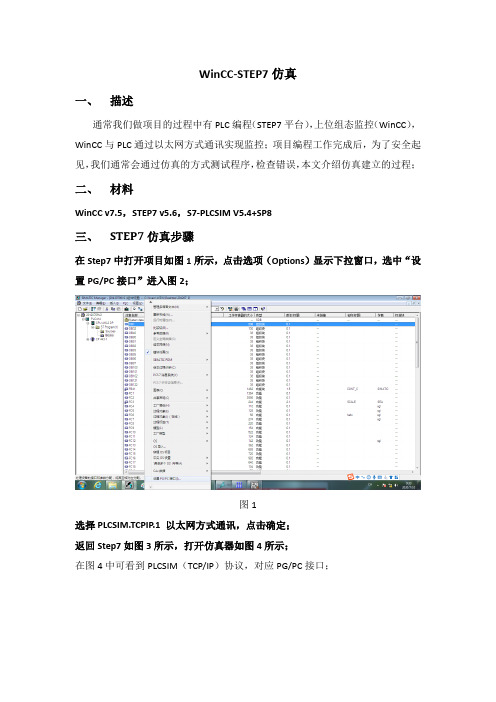
WinCC-STEP7仿真一、描述通常我们做项目的过程中有PLC编程(STEP7平台),上位组态监控(WinCC),WinCC与PLC通过以太网方式通讯实现监控;项目编程工作完成后,为了安全起见,我们通常会通过仿真的方式测试程序,检查错误,本文介绍仿真建立的过程;二、材料WinCC v7.5,STEP7 v5.6,S7-PLCSIM V5.4+SP8三、STEP7仿真步骤在Step7中打开项目如图1所示,点击选项(Options)显示下拉窗口,选中“设置PG/PC接口”进入图2;图1选择PLCSIM.TCPIP.1 以太网方式通讯,点击确定;返回Step7如图3所示,打开仿真器如图4所示;在图4中可看到PLCSIM(TCP/IP)协议,对应PG/PC接口;图2图3图4PLC处于STOP模式见图4,如图5所示下载程序到仿真器(全部内容);打开OB1如图7,点击在线如图8所示,且在状态栏可知PLC状态为STOP;图5图6图7图8打开仿真器,将PLC状态调整为RUN-P如图9,至此STEP7仿真成功;图9图10四、WinCC仿真步骤打开WinCC项目如图10所示,点击“变量管理”->“SIMATIC”-> “TCP/IP”-> “系统参数”在“系统参数-TCP/IP”->“逻辑设备名称”设置为PLCSIM.TCPIP.1图11在“变量管理”->“SIMATIC”-> “TCP/IP”-> “PLC1”中右击连接参数-TCPIP 如图12所示,在IP地址栏需要输入PLC的IP地址;如何查看PLC的IP地址:在STEP7中选择图13中hardware,进入图14,点击硬件CP443-1的属性即可查看PLC的IP地址;注:WinCC修改变量管理中的通讯参数之后再重新启动WinCC图12图13图14。
Step7 V5.5 SP4安装教程
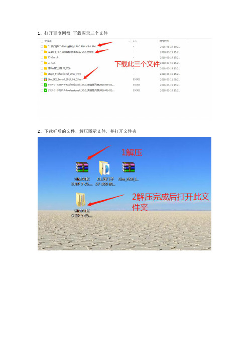
1、打开百度网盘下载图示三个文件
2、下载好后的文件,解压图示文件,并打开文件夹
3、双机Setup开始安装,注意一定关闭杀毒软件
4、提示重新启动
5、选择开始-->运行(或者WINDOS+R)输入regedit打开注册表,
在注册表内“HKEY_LOCAL_MACHINE\System\CurrentControlSet\Control\Session Manager\”中删除注册表值“PendingFileRenameOperations”不要重新启动,继续安装软件。
6、重复第3步,开始安装
7、默认选择中文,单击下一步
8、等待中。
9、勾选我接受后,单击下一步
10、默认选择,单击下一步
11、勾选我接受后,单击下一步
12、开始安装
13、单击下一步
14、单击下一步
15、默认用户名和组织,单击下一步
16、选择典型,点击更改选择安装位置(建议安装在C盘根目录下,不要有中文路径)正常默认是在C:\Program Files\Siemens\Step7这样的文件夹中
17、默认选择下一步
18、选择【否,以后再传送许可】单击下一步
19、单击安装
20、安装中。
21、安装中无需操作
22、安装中无需操作
23、安装中无需操作
24、单击确定
25、选择【是,重启】,单击完成,安装完成
旺旺ID:冯帅07
淘宝旺铺:工控小羽(单击进入店铺)
谢谢大家关注,希望您工作愉快,事业顺利。
02.Step7V5.5SP4安装教程及授权

Step7 V5.5 SP4软件安装教程安装前必须关闭杀毒软件和安全卫士等。
否则安装失败后果自负概不退款的,安装软件默 认磁盘安装不要随意更改磁盘路径,私自更改安装失败后果自负注意事项:OPZ W 呎* g ,2 呎Bitte fuhren Sie &:nen Nsustazt 耳us tevci Sx&pToerazEi& inEta.-lier&n.Vsuillsz xtdixiirsr ordinaavant d 2 inEtallfti d 3 ALstrtE pTOEra=nv£. Ant«s de inEt&liir otros praera^as : poi f avor ; rslnLci* al S3.u ;ipo. Frisa. di installSLre 且Ltri crofirazczi- a^iare- nuovaosnte il sistezia.有的人电脑安装step7的时候会提示上图错误对话框 现在给出以下解决方案!如果不提示请直接安装!很多人受西门子软件安装需重新启动机器,然而启动机器后又提示重新启动机器,然而反复重新启动仍然出现这样的提示,导致软件不能安装。
现在给出解决方案:在注册表内 HKEY_LOCAL_MACHINE\System\CurrentControlSet'Control'SessionManager\ ”中删除注册表值Pendin gFileRe nameOperati ons ”不要重新启动,继续安装软件。
现在可以安装更多程序而无需重启计算机了。
如图:647 1,046 1.352 2,933 49 203 B73 1,3931 3,280 231一 SeC Q n_x64, exe. man if est」Setup,ex_ 魁 Setup.exe (. Setupt,cfg2010/4/15 8;55 2011/11/7 B;18 MANIFEST EX_文件 2011/3/3 13:322010/3/10 15:57 CFG 文祥' LI i.eZrTI O 5 rTl nt■i MSCOMCT2.OCX2M4/3/B 22:00 ActiveX 控件 iQrrara-^女件电】漏皤M 至看M 收星灭⑥ 辂助妁口 Fri arityContrsl Cj FroductOptions1+1 LJ EtlQueryRegi EtryConfiW O SafoBoot SI l_J Set 1 Per I |+] __ I S AC 'DI "A P I pdS«rvArisQ U _l u s _| 1- Siciu :- i tyTrova dltrs Server Kppl L c ati OILS :Servi ceCurrent Ssrvi 亡芒Gt* ^opOz 1 der Serv it 电Frt^i dtrU KppCcnpat i b ilft :Ajjpfalches DOS Devices _J Envirciment _IEx«rat;i v«J mR wn^&Dp.E-fiL 七丨呦晝. -I _l sD 丨2 主nO 由 口 StillLn&ge 田 Qj SystemftesourcesTeman^l Server I Tin4ZQTi«lD£«rmatuoxikar*n.«lKnawnDLLsBemory M am.a.gen ent.Power SFCSubsist e>TiE类型丁数垢亟軟认〕RZG_SZ職值耒设豈)踊 Ml oChkT imtOTitRIG_prQRDIMM000005 CS) tExe cutfeRIGJflULTI^SZ n-utcchcck Aut ochk *i S^Cr i ti亡 吃 I i oxi! i fk^outRIGJZiFQED Q 灿ETBdDO ^590000) 掘]En 通:L E RCARIGJVOEDaxDooaocoi (i)翩 EnbbleMER1G_DVORD O K O OODOOOO un更| E 辭1诃总ks 心啊rJJll* R2C_MVLTI_S1錮 GLnliJFl 帕RIG_;Dfi ,OED axooaxxaa 血) ,S^|HiiipD*CiMii iFfeiBltskThr... RIG —DLOED awoooaocDa m jK^HeapDeCorwni iTotalFreelhr..RIG.D 和RDOWOOOODODO go礙]H« apSecni «ntC orrmi tR2G_DrORDoxoooooooo a)=pS •测 d-nt.K.as«rva-RIGJVOBD O K OOOOOOC I O 紛jSolU. c e-nse dProc e-szor s.RI^DIfOED (hooaxxD^ 臣 jirecl4rie5RIG MULH SZ\WiffLdiws \EFC Con.tr &1 db'fendi n^ji 辽 eKenan eOper ati ons; MGJIVLTIJZ\7?\C : ^Documents and :閥| F MEM orC^ntrol RIGJtfOKD(M10000002 C2)S»]Pr o t «ct 3 C'TuW o At RIGJJKBDOxOOOOOCOl a) jn^Re gi stcr edPr ttecs s^rsRIG_IiFCIED axoooaooD?斜 廖]赵 E o-urc $Ti 砒 autCeiml RIG_DVOEDaxD009e340 ®48OC0)2J我的fasa \HKET WC JkLJflJkCHIWT \EYS7EM\Cnntr □!£• 1001 \C DJitrnl\S ■ 1= i on Mm •刖r |;Ptn (liTkgFil#K|[fiyjProcessarCon圏Ffottct 】皿耐 Kj{]Ke§isteredPr [fl^] Re sour ctl 1m 包 修改二进泣数据0) 删除①) 重命名腿) 右击删除! 【XP 系统注册表打开方法:开始菜单T 运行T 输入regedit 宀按enter 回车键即可进入】 【Win7 32位或64位系统注册表打开方法:开始菜单T 搜索程序和文件T 输入 regedit T 按 enter 回车键即可进入】 谢(1) 勇 regedit.exe1将安装包下载到F盘,新建一个以英文命名的文件夹,文件夹里不能有中文。
西门子SIMATIC STEP7 V5.5 SP4配置指南说明书

How to configure SIMATIC STEP7 V5.5 SP4 to read acyclic data from MultiRanger/HydroRanger 200 HMI over SmartLinx PROFIBUS DPV1Application examples Introduction1 Overview2 Planning/configuring3Siemens AGGlobal Services Information Technology Document order number: AG090315Ⓟ 09/2020 Subject to changeCopyright © Siemens AG 2020.All rights reservedLegal informationWarning notice systemThis manual contains notices you have to observe in order to ensure your personal safety, as well as to preventdamage to property. The notices referring to your personal safety are highlighted in the manual by a safety alertsymbol, notices referring only to property damage have no safety alert symbol. These notices shown below aregraded according to the degree of danger.DANGERindicates that death or severe personal injury will result if proper precautions are not taken.WARNINGindicates that death or severe personal injury may result if proper precautions are not taken.CAUTIONindicates that minor personal injury can result if proper precautions are not taken.NOTICEindicates that property damage can result if proper precautions are not taken.If more than one degree of danger is present, the warning notice representing the highest degree of danger willbe used. A notice warning of injury to persons with a safety alert symbol may also include a warning relating toproperty damage.Qualified PersonnelThe product/system described in this documentation may be operated only by personnel qualified for the specifictask in accordance with the relevant documentation, in particular its warning notices and safety instructions.Qualified personnel are those who, based on their training and experience, are capable of identifying risks andavoiding potential hazards when working with these products/systems.Proper use of Siemens productsNote the following:WARNINGSiemens products may only be used for the applications described in the catalog and in the relevant technicaldocumentation. If products and components from other manufacturers are used, these must be recommendedor approved by Siemens. Proper transport, storage, installation, assembly, commissioning, operation andmaintenance are required to ensure that the products operate safely and without any problems. The permissibleambient conditions must be complied with. The information in the relevant documentation must be observed. TrademarksAll names identified by ® are registered trademarks of Siemens AG. The remaining trademarks in this publicationmay be trademarks whose use by third parties for their own purposes could violate the rights of the owner. Disclaimer of LiabilityWe have reviewed the contents of this publication to ensure consistency with the hardware and softwaredescribed. Since variance cannot be precluded entirely, we cannot guarantee full consistency. However, theinformation in this publication is reviewed regularly and any necessary corrections are included in subsequenteditions.Table of contents1 Introduction (4)1.1 Objective (4)1.2 Equipment (4)1.3 Disclaimer (4)2 Overview (5)3 Planning/configuring (6)3.1 Modifying GSD to perform acyclic communication (6)3.2 Slot index table (6)3.3 Adding MultiRanger/HydroRanger 200 HMI to the hardware configuration (7)3.4 Step7 example program (8)3.5 Slot index table (10)3.6 How to test using the VAT table (14)1.1ObjectiveThe objective of this application guide is to help the user become familiar with the stepsrequired to use acyclic communications through a SmartLinx PROFIBUS DPV1communications module to read/write data to MultiRanger/HydroRanger 200 HMI.1.2EquipmentNoteA complete code example is available for the Siemens SIMATIC S7300 PLC.This guide is an addition to the application guide Step7 V5.5 SP4 MR_HR _HMI. Please usethe Step7 V5.5 SP4 MR_HR _HMI application guide to setup the cyclic data before using thisguide.This guide assumes the user is familiar with Step V5.5 SP4.1.3DisclaimerNoteWhile every effort is made to verify the following information, no warranty of accuracy orusability is expressed or implied.All names identified by ® are registered trademarks of Siemens AG. The remaining trademarksin this publication may be trademarks whose use by third parties for their own purposescould violate the rights of the owner.This application guide is an addition to the operating instructions forMultiRanger/HydroRanger 200 HMI. It focuses on the setup and configuration of the S7300, using specific functions in the PLC, SFC58 (WR_REC), and SFC59 (RD_REC), to access the MultiRanger/HydroRanger 200 HMI parameters.Acyclic communication through PROFIBUS DPV1 is designed to allow read/write access to the PROFIBUS slave device. During normal operation of a PROFIBUS network, data is exchanged cyclically between the master and slave devices. If an acyclic request occurs, the Class I master will pass the request to the slave device. After the cyclic data has been read from the slaves, the acyclic request is sent to the slave. The slave device will then process the request and respond in the current scan or the next scan. Acyclic requests are executed periodically because parameter data is not required as frequently as the cyclic data.The example below will show you how to read/write the quick start parameters in MultiRanger/HydroRanger 200 HMI. The PLC code example uses a timer interrupt, OB35 (TIMER_INTERUPT), to indirectly call SFC58 and SFC59. In this example, OB35 is executed every 100 ms.Planning/configuring 3 3.1Modifying GSD to perform acyclic communication1.To allow acyclic communications through a Class I master, you must change the C1 and C2response timeout.2.Open the GSD file, HMSB1813.gsd, in Notepad and change the C1 and C2 timeout as shownbelow.Save the file.Use this GSD file to configure hardware in Step7.3.2Slot index tableThe parameters, or diagnostic information, in the PROFIBUS slave device are arranged in astandard way and are accessed through the slot index table. The table defines whereinformation is stored in the device and references the slot and index for a parameter ordiagnostic.3.3 Adding MultiRanger/HydroRanger 200 HMI to the hardware configuration 3.3Adding MultiRanger/HydroRanger 200 HMI to the hardwareconfigurationTo add the MultiRanger/HydroRanger 200 HMI to the hardware configuration, you will needto add the device to the network and define the number of modules required. A moduleholds a group of parameters or diagnostic information for the device. The total number ofmodules must match the number of modules in the slot index table. The number of bytes ineach module must add up to the total number of bytes used for cyclic data exchange. For theMultiRanger/HydroRanger 200 HMI, this is 19 words of input.In the Step7 hardware configuration you will see that 6 modules have been added forMultiRanger/HydroRanger 200 HMI.Slot/Module Description1 Parameters for channel 12 Parameters for channel 23 Global parameters4 Relays5 Device6 Echo profile (internal use)NoteThe number of modules used in the cyclic data configuration is related to the number of slotsused for acyclic communications. Therefore, in order to access all 6 acyclic slots, 6 modulesmust be used in the hardware configuration.3.4 Step7 example program3.4Step7 example programThis example will show you how to read/write the quick start parameters for theMultiRanger/HydroRanger 200 HMI by referencing the index from the slot index table. In theslot index table, the quick start parameters for point 1 start at slot 1, index 50.1.In step7 V13, add OB35.2.Inside OB35, insert a network for SFC58 and SFC59. OB35 will execute every 100 ms andcall SFC58 and SFC59.3.Read the quick start parameters from the MultiRanger/HydroRanger 200 HMI and move thedata to DB1.If M100.1 is closed, SFC59 is called and will write the parameters from DB1 (Quick start 2) tothe MultiRanger/HydroRanger 200 HMI.The complete code for OB35 is shown below:3.4 Step7 example program SFC59 (RD_REC) parametersREQ Start the requestIOID Module typeLADDR Address of the module1: 256 (0 x 100)RECNUM Index: 50 (0 x 32)P#DB1.DBX0.0 Data block holding the result of the parameter readBUSY Function statusRET_VAL Result of the functionSFC58 (WR_REC) parametersSome additional logic is used to disable the RD_REC while the RD_WRI is being executed. REQ Start the requestIOID Module typeLADDR Address of the module 1: 256 (0x100)RECNUM Index: 50 (0x32)P#DB1.DBX12.0 Data block where data will be read from and sent to MultiRanger/HydroRanger200 HMIBUSY Function statusRET_VAL Result of the function3.5 Slot index tableEnabling M100.0 will initiate a RD_REC if a RD_WRI is not being executed.Enabling M100.2 will initiate a RD_WRI and disable a RD_REC while the RD_WRI is beingperformed. When the WR_REC is complete, M100.2 will be cleared to disable the WR_REC call.Refer to the slot index table below for the data type for each parameter. If you are writingto the MultiRanger/HydroRanger 200 HMI, enter the data into the data structure inDB1.DBX12.0 (Quick start 2).3.5Slot index table3.5 Slot index table3.5 Slot index table3.5 Slot index table3.6 How to test using the VAT table3.6How to test using the VAT table1.Create a VAT table to test the read/write function.e M100.2 to enable the WR_REC and send the Quick start 2 to theMultiRanger/HydroRanger 200.。
step7 v5.5cn

SIMATIC用于SIMATIC S7 / M7 / C7的STEP 7 V5.5编程软件安装与使用注意事项该注意事项中包含的信息相对于其它文档来说是最新的。
请仔细阅读,此文本中包含了有关STEP 7 V5.5的安装与使用信息。
对该版本的重要修订以斜体显示,并标有注释“从该版本开始新增的内容”。
请注意,对于A4格式,所要打印文件的左右边距都设置成25 mm。
目录安装注意事项1发货清单2硬件要求3软件要求3.1运行环境3.2需要的存储空间3.3与其它软件产品的兼容性3.3.1Rational ClearCase配置管理工具3.3.2使用其它软件产品时的网络设置3.4在线文档4安装4.1安装STEP 7 V5.54.2升级旧版STEP 74.3STEP 7 V5.5许可证密钥4.4删除STEP 7 V5.54.5安装时的其它注意事项4.5.1使用滚轮鼠标4.5.2使用PC/PG通信卡时的注意事项使用注意事项(版本注释)5新版软件的新特性和所作的修改6组态和操作软件时的注意事项6.1STEP 7如何满足IEC标准6.2常规注意事项6.3使用网络驱动器6.4多用户操作6.5多重项目6.6交换不同版本的STEP 76.7库文件和实例项目6.8SIMATIC管理器6.9使用符号名6.10硬件配置(中央机架)6.11硬件配置(PROFIBUS DP)6.12硬件配置(PROFINET IO)6.13冗余I/O:通道间隔冗余6.14硬件诊断6.15MPI / PROFIBUS网络设置6.16SIMATIC M76.17梯形图、功能块图、语句表和参考数据6.18翻译文本6.19管理多语言文本6.20将S5程序转换成S7程序6.21将TI程序转换成S7程序6.22容错系统6.23使用外文字符集时的注意事项6.24使用SIMATIC Logon的注意事项6.25命令接口6.26TCI –工具调用接口6.27MS Windows 7操作系统的特性7文档注意事项8使用STEP 7中文版时的重要特性安装注意事项本注意事项中包含您在安装STEP 7 V5.5时所需的重要信息,在安装该软件以前请务必详细阅读该注意事项。
STEP---7计算机仿真

第五节STEP---7计算机仿真
在程序编完以后先应该在计算机上进行仿真实验,保证程序能够执行导通,然后进行下载。
下面是计算机仿真的具体步骤。
首先,编程并且对程序的最小化,以及调用OB功能块这些步骤,都必须有,然后进行仿真。
第一步是打开仿真界面,如下图所示。
点击该键进入仿真界面
第二步是下载程序到仿真软件里,点住SIMATIC 313C然后下载,如下图所示。
点击该键下载到仿真软件里。
根据程序的需要在仿真软件里进行仿真,主要是看程序是否能运行所以需要打开S7—GRAPH编程界面戴上眼镜,进行仿真;仿真需要一步一步的进行,首先点击程序的第一步看是否能运行结果(在S7—GRAPH编程界面里观察)。
点击该键表示选者START信号高电平有效,再点击到RUN上面看程序是否往下运行,以后每一步都需要这样点击检测信号,看QB块里的对应运行是否动作。
当点击下START键,再点击RUN如果程序是通的话,则在S7—GRAPH界面将出现如下所示的界面,表示程序是通的,每一步的程序仿真都需要将执行如上步骤,先输入检测信号,然后到S7—GRAPH,里进行监控。
如何使用STEP7V5.5对模拟量值标准化和去标准化?.doc

说明模拟量输入模块提供模拟量信号(电流,电压,电阻或温度)的标准化的数值。
这些数值一定要能体现测量的参数(例如,以公升为单位的液位)。
这一过程称为模拟量的标准化或标定。
相对应的用户程序计算出过程值,过程值必须转换成一个数值,这一数值能使模拟量模块转换成模拟量信号,进而使得此模拟量信号能都驱动一个模拟量执行机构。
这一转换过程称为去标准化。
下面提供的下载的功能库可以用来实现模拟量的标准化和去标准化。
图01 展示了标准化的示例。
图 01图02展示了去标准化的示例图 02y值始终是转换结果,x值是已知的参数。
可装载的这4个功能不同之处在于y和x对应的数据类型。
1.FC164对应的x值是整数,y值是整数。
2.FC164对应的x值是整数,y值是实数。
3.FC164对应的x值是实数,y值是整数。
4.FC164对应的x值是实数,y值是实数。
通过输入yMIN 和yMAX可以将低于低限,高于高限的值限定到范围值y内。
通过这种方式过滤掉模拟量输入和输出模块的高于量程限度和低于量程限度的区域。
所以Y值是根据线性方程式y = a x + b来计算这取决于下面的关系式:y = (y1-y0) / (x1-x0) * (x-x0) + y0通过FC165(整数〉实数)线性规格化示例图 03模拟量输入板模块检测到4~20mA的输入信号。
这一信号转换到CPU内部的值对应范围0~27648。
液位就是用这种方式测量的。
如示例所示4mA对应液位0.0m,20mA对应液位1.7m。
这取决于下面的参数:P0(x0=0; y0=0.0)P1(x1=+27648; y1=+1.7)可以这样调用FC165:CALL FC165x:= PEW20yMIN:= 0,0yMAX:= 1,7x0:= 0y0:= 0,0x1:= 27648y1:= 1,7y:= MD22说明参考手册“S7-300自动化系统模块数据” (条目号8859629)第5章节“模拟量模块的模拟值表示”查看电压、电流、电阻和温度范围对应到CPU内部的范围值。
STEP7-V5.5-sp2-CN安装步骤

STEP7 V5.5 sp2 CN安装步骤一、首先右击STEP7 V5.5 sp2 CN.iso文件解压到STEP7 V5.5 sp2文件夹〔或者解压到随意的英文文件夹中,如果有中文安装时会提示未找到ssf〕;二、打开STEP7 V5.5 sp2文件夹,双击setup.exe,进展安装,如果提示电脑需要重启或如下图那么需要在电脑的注册表里删除一个注册表就不提示重启了,具体方法:运行注册表命令regedit,在注册表“HKEY_LOCAL_MACHINE\System\CurrentControlSet\Control\Session Manager\〞中删除注册表“PendingFileRenameOperations〞,右击它删除。
如果不会打开注册表,请百度一下。
三、双击setup.exe之后,选择安装简体中文,如图下一步。
四、选择本人承受,下一步。
五、打对勾,选择下一步。
六、承受设置的更改,下一步。
七、程序进入安装状态,大概会花费十几分钟。
进入逐个程序安装,到这里选择下一步。
继续下一步。
下一步。
在此选择典型安装,您可以选择安装到其他磁盘,下一步。
选择简体中文,下一步在此选择否,以后再传送,下一步。
在此点击安装,程序会继续进展安装。
选无,确定。
选择立即重启电脑,重启完后再授权。
重启后电脑桌面上会多三个图标八、授权说明,授权分windows xp和windows 7授权先介绍xp授权:有安装说明,不再细说。
Windows 7授权:打开这个1,2,3操作完就行了,到此安装,授权完全,你可以放心的使用该软件了。
- 1、下载文档前请自行甄别文档内容的完整性,平台不提供额外的编辑、内容补充、找答案等附加服务。
- 2、"仅部分预览"的文档,不可在线预览部分如存在完整性等问题,可反馈申请退款(可完整预览的文档不适用该条件!)。
- 3、如文档侵犯您的权益,请联系客服反馈,我们会尽快为您处理(人工客服工作时间:9:00-18:30)。
1.打开step7软件SIMATIC Manager,新建名为“today”的项目,如下图
2.若要进行仿真,即在项目名称上插入新对象---S7程序。(仿真无需硬件组态)
3.在“块”中双击打开OB1,选择LAD梯形图进行编程。
在该界面上编写程序,比如一个简单的启停程序。
4.保存并下载,若出现下列两种情况:
情况4.1 未配置站点地址
此处因没有硬件组态,所以不能依附在某一硬件上编程,但可创建一个临时的站点(此方法
可重复使用)。如下图输入IP地址(即本机IP)
或者输入PROFIBUS 地址(按要求随意输入)
情况4.2如下图,即需要打开仿真器
回到之前建立的项目界面打开仿真器(若是灰色,则需安装,地址:
https://pan.baidu./s/13yH4dZLe-sb2hJZ7-hFQEA 密码:qw5z)
分别是CPU、输入和输出(如果没有,可在插入选项卡中输入输出)
5.再返回到程序OB1界面,进行下载程序(若出现上述两种情况,可重复其解决方法)
下图为下载该程序后,点开监视按钮的界面,为“stop”状态
只要将仿真器拨到RUN,即可开始仿真
Welcome to exchange questions!