Corona of Magnetars
CORONA 2.4GHz Spread Spectrum (FASST COMPATIBLE) R

CORONA 2.4GHz Spread Spectrum (FASST COMPATIBLE)Receiver Instruction Manual for R4FA‐SB and R6FA‐SB Compatibility:The CORONA 2.4GHz Spread Spectrum FASST Compatible Receiver is designed for use with FUTABA’s FASST 2.4GHz transmitters; including the 3PM,3PKS,3VCS,3GR,4PK(S),TM7, TM8, TM10, TM14 and the T6EX‐2.4G, 7C‐2.4G, 8FG, 10CG, 12FG. The R4FA‐SB and R6FA‐SB receivers supply a more useful mode for users. Both the R4FA‐SB and R6FA‐SB support FUTABA’s FASST air system and surface system. The R4FA‐SB supports 7‐channel with continuous PPM (positive and negative) output ,RSSI output and S.BUS output, R6FA‐SB supports 6 channel high speed PPM(HS) mode to optimize helicopter response control and S.BUS output.Under S.BUS output mode, both R4FA‐SB and R6FA‐SB supply 12 proportional channels and 2 DG channels. Therefore, the R4FA‐SB or R6FA‐SB becomes 14‐channel receivers when using S.BUS output.Specifications:Operating Current: 50mA maxOperating Voltage: 3.6 ~10VLatency: R4FA‐SB’s description14mS for independent 4 channel output and S.BUS output @ FASST multi‐channel mode21mS for Continuous PPM output and RSSI output@ FASST multi‐channel mode16mS for independent 4 channel output and S.BUS output @ FASST 7ch mode24mS for Continuous PPM output and RSSI output@ FASST 7ch mode14mS for independent 3 channel output@ FASST surface system C1 CODE modeR6FA‐SB’s description7mS for independent 6 channel (HS) output@ FASST multi‐channel mode14mS for independent 7 channel (LS) output and S.BUS output @ FASST multi‐channel mode 8ms for independent 6 channel (HS) output@ FASST 7ch mode16mS for independent 7 channel (LS) output and S.BUS output @ FASST 7ch mode14ms for independent 3 channel output@ FASST surface system C1 CODE modeSensitivity: about ‐100dBmOperation temperature:‐10~80 deg CSetup:Bind procedure:∙Turn on the FASST transmitter∙Connect the battery to the receiver while pressing the receiver’s F/S button.∙The Dual‐color LED’s will continuously cycle through the following:o Red LED light (searching radio signal)o Green LED light (acquired the radio signal)o Red LED off (bind ok)o Green LED flashes 10 times (ID stored in memory)o Green LED lights solid (normal operation)Note: FASST surface systems take a bit more time to complete the bind procedure.Fail‐safe setting:There are two ways to set the Failsafe setting on the CORONA 2.4GHz Spread Spectrum FASST Compatible Receiver;1.TX‐failsafe feature: This method sets the failsafe on the FASST transmitter and has priority (works onchannel 3 only under FASST 7ch mode or on multiple‐channels under FASST multi‐channel mode) while the receiver is on, just like FUTABA receivers (only available on FASST air system).2.RX‐failsafe feature: Turn on the FASST transmitter and then turn on the CORONA 2.4GHz Spread SpectrumReceiver, put all the sticks and switches to control inputs you want if the receiver looses signal and Press the F/S button down for about 5 ‐ 6 seconds while the Green LED lights solid (Rx in normal operation), then release the button. You will see the Red LED will flash for about 4 ‐ 5 seconds. (Note: The Red LED will FLASH high speed to indicate the RX‐failsafe is turned on OR FLASH low speed to indicate the RX‐failsafe is turned off). If you press the F/S button a second time while the Red LED is flashing, the receiver will change its RX‐failsafe status (on / off), then the LED will return to Green solid again. If you not press the F/S button, nothing will be changed and the LED will return to solid Green. If you want to cancel the RX‐failsafe feature (not just turn it off), you can do so by binding the receiver again. After binding operation the receiver will be back to factory settings without any failsafe feature.Note: If you do not set a failsafe setting, the receiver will hold all controls at the position of the last command received before signal was lost. When RX‐failsafe is turned on, the receiver will initiate the RX‐failsafe settings after loosing signal for over 1 second and the receiver will hold the last received positions until the failsafe takes over. When the RX‐failsafe and TX‐failsafe feature are both turned on, the receiver will use the TX‐failsafe command.We highly recommend you set failsafe feature before flying your models. An example of a minimal useful, failsafe setting would be to shut down the model’s throttle, so that it does not fly or drive away uncontrolled.Output mode setting (only available on FASST air system):Turn off the transmitter, connect the battery to the receiver, you will see the Red LED light flashing. The RED LED flashes at high speed to indicate the receiver is in the special output mode OR a Low speed indicates the receiver is under (LS) low speed PPM normal output mode, press the F/S button for 5‐6 seconds while the Green LED is off (Rx in signal searching status), then release the button. You will see the Green LED flash for about 4 ‐ 5 seconds. (Note: The Green LED will FLASH high speed under special mode OR FLASH low speed under normal output mode). If you press the F/S button a second time while the Green LED is flashing, the receiver will change its output mode status (special/normal), if you do not press the F/S button the output mode will not be changed and the Red LED will flash at its original speed.Note: Output mode function is described in the form below,R4FA‐SB R6FA‐SBnormal Ch1~CH4 independent PPM output normal Ch1~CH7 independent PPM outputCH1 Neg CPPM out(FUTABA trainer FUNC)^1 CH2 Pos CPPM out for special user^2 CH1~CH6 independent high speed(HS)PPM out for helicopter fast response controlCH3 RSSI PWM out for FPV()^3 specialCH4 S.BUS output for compact system specialCH7 S.BUS output for compact systemNote: ^1 refer the signal description picture below^2 refer the signal description picture below^3 refer the signal description picture belowRSSI PWM out define: Pulse width from about 900uS~ 2100uS to indicate RSSI strength from ‐100dBm~‐40dBm.Important Note: If you are using analog servos in your model you must keep your receiver under the factory settings (normal output mode) or your analog servo will get hot and possibly burn out. As well you cannot use a non S.BUS servo on a channel while S.BUS signal output present.LED status indicated under normal working status:RED LED GREEN LED Statusflash off No signal searchedoff solid Signal is very goodSometime flash solid Signal is not very goodflash flash Signal is weak。
SAE J1773电动汽车耦合充电系统连接

SAE Technical Standards Board Rules provide that: “This report is published by SAE to advance the state of technical and engineering sciences. The use of this report is entirely voluntary, and its applicability and suitability for any particular use, including any patent infringement arising therefrom, is the sole responsibility of the user.”SAE reviews each technical report at least every five years at which time it may be reaffirmed, revised, or cancelled. SAE invites your written comments and suggestions.TO PLACE A DOCUMENT ORDER: (724) 776-4970 FAX: (724) 776-0790SAE WEB ADDRESS Copyright 1999 Society of Automotive Engineers, Inc.4.4.1.2Orientation (10)4.4.1.3Connection Present Magnet Location (10)4.4.1.4Connection Present Magnet Strength (10)4.4.1.5Tactile Feel Indents (10)4.4.1.6EMI Shield Contact Zone Location (10)4.4.1.7EMI Shield Contact Zone Impedance (10)4.4.1.8IR Transceiver Interface Location (10)4.4.1.9Stop Receptacle Locations (12)4.4.2Inductive Vehicle Inlet (12)4.4.2.1Critical Dimensions (12)4.4.2.2Alignment (12)4.4.2.3EMI Shield Contact Zone Location (12)4.4.2.4Grounding of EMI Shield Contact Zone (13)4.4.2.5IR Transceiver Alignment (13)4.5Electromagnetic Emissions (13)4.5.1SAE Charging System Requirements (13)4.5.2FCC Charging System Requirements (13)5.Application Requirements (14)5.1Environment (14)5.1.1Performance Requirements (14)5.1.1.1External Touch Temperature (14)5.1.1.2Operational and Storage Temperature (14)5.1.1.3External Contaminants (14)5.1.1.4Vibration (14)5.1.1.5Pass Criteria (14)5.1.1.6Material (14)5.1.1.7Fluid Egress (14)5.2Charger Requirements (14)5.2.1Power Level Compatibility (14)5.3Vehicle Requirements (14)5.3.1Power Level Compatibility (14)6Notes (14)6.1Marginal Indicia (14)Appendix A Software Interface (15)A.1Scope (15)A.2Software States (15)A.3Message Structure (18)A.4Message Definitions (20)A.4.1Vehicle-to-Charger Messages (20)A.4.2Charger-to-Vehicle Messages (23)A.5Fault Detection and Handling (25)A.6Message Summary (26)A.7Glossary (26)Appendix B Level 3 Compatibility (27)B.1Scope (27)B.2Level 3 Power Compatibility System Design (27)B.2.1Hardware Power Level Comparison Requirements (28)B.2.2Software Power Level Comparison Requirements (28)B.3Charger Controller Requirements (28)B.4Vehicle Charge Controller Requirements (28)Appendix C Compatibility With Existing Systems (29)C.1Scope (29)C.2Communications Metrics (29)C.3RF Antenna Location (30)C.4FCC Charging System Requirements for RF Systems (30)C.5Inductive Connector Physical Compatibility (30)Appendix D138 mm Coupler (31)D.1Scope (31)D.2Coupler Dimensions (31)D.3Inlet Core Dimensions (34)1.Scope—This SAE Recommended Practice establishes the minimum interface compatibility requirements forelectric vehicle (EV) inductively coupled charging for North America.This part of the specification is applicable to manually connected inductive charging for Levels 1 and 2 power transfer. Requirements for Level 3 compatibility are contained in Appendix B. Recommended software interface messaging requirements are contained in Appendix A.This type of inductively coupled charging is generally intended for transferring power at frequencies significantly higher than power line frequencies. This part of the specification is not applicable to inductive coupling schemes that employ automatic connection methods or that are intended for transferring power at power line frequencies.1.1General Inductive Charging System Description—The basic principle behind inductive charging is that thetwo halves of the inductive coupling interface are the primary and secondary of a two-part transformer. When the charge coupler (i.e., the primary) is inserted in the vehicle inlet (i.e., the secondary), power can be transferred magnetically with complete electrical isolation just as it occurs in a standard transformer. The number of turns (windings) on the secondary is “matched” to the vehicle’s battery pack voltage so that the same charger can charge any vehicle.The charger converts utility power to high frequency AC (HFAC) power (130 kHz to 360 kHz). The high frequency operation is utilized to reduce the size and mass of the on-vehicle portion of the transformer. The vehicle inlet is the power inlet on the vehicle which receives the HFAC from the charger. The HFAC is converted into DC to charge the batteries. An on-vehicle charge controller continuously monitors the state of the batteries during charging and controls the charger output power level via an IR communications link between the vehicle inlet and the charger (the charger’s communications interface is physically imbedded in the charge coupler). The charge controller signals the charger to stop charging when it determines that the batteries are completely charged or a fault is detected during the charging process.The following steps correspond with the diagram in Figure 1, and describe the closed-loop charging system.a.Vehicle charge controller determines desired current into batteries. **b.Vehicle charge controller transmits charger output power request to charger via an IR communicationsinterface. **c.Charger controls input current from utility based on charger output power request from vehicle chargecontroller. **d.Charger converts 60 Hz utility power to HFAC power.e.HFAC power is magnetically coupled from the coupler (primary) to the vehicle inlet (secondary).f.HFAC power is rectified/filtered to DC to charge the vehicle batteries.g.Process repeats until the vehicle charge controller determines the batteries are fully charged. **NOTE—Items with ** indicate control loop.FIGURE 1—TYPICAL CLOSED-LOOP CHARGING SYSTEM.2.References2.1Applicable Publications—The following publications form a part of this document to the extent specifiedherein. Unless otherwise indicated, the latest issue of SAE publications shall apply.2.1.1SAE P UBLICATIONS—Available from SAE, 400 Commonwealth Drive, Warrendale, PA 15096-0001.SAE J551-2—Test Limits and Methods of Measurement of Radio Disturbance Characteristics of Vehicles, Motorboats, and Spark-Ignited Engine-Driven DevicesSAE J551-5—Performance levels and Methods of Measurement of Magnetic and Electric Field Strength from Electric Vehicles, Broadband, 9 kHz to 30 MHzSAE 1211—Recommended Environmental Practices for Electronic Equipment DesignSAE J1850—Class B Data Communications Network InterfaceSAE J2178—Class B Data Communication Network MessagesSAE J2293—Energy Transfer System for Electric Vehicles2.1.2F EDERAL C OMMUNICATIONS C OMMISSION (FCC)—Available from U.S. Government Printing Office,Superintendent of Documents, P.O. Box 371954, Pittsburgh, PA 15250-7954.CFR 47—Code of Federal Regulations, Title 47, Parts 15B, 18CCFR 40—Code of Federal Regulations, Title 40, Part 600, Subchapter Q2.1.3U NDERWRITERS L ABORATORIES, I NC.—Available from Underwriters Laboratories, Inc., 333 Pfingsten Road,Northbrook, IL 60062-2096.UL 94—Tests for Flammability of Plastic Materials for Parts in Devices and AppliancesUL 2202—Electric Vehicle (EV) Charging System Equipment2.2Related Publications2.2.1NFPA P UBLICATION—Available from the National Fire Protective Association, Batterymarch Park, Quincy,MA 02269.NFPA-70-1999—National Electric Code (NEC)‚ - Article 6252.2.2C ANADIAN E LECTRIC S TANDARDS—Available from: Canadian Standards Association, 170 Rexdale Blvd.,Rexdale, Ontario, Canada M9W 1R3Canadian Electric Code*CEC Part 1, Section 863.Definitions3.1Electric Vehicle (EV)—An automotive type vehicle, intended for highway use, powered by an electric motorthat draws current from an on-vehicle energy storage device, such as a battery, which is rechargeable from an off-vehicle source, such as residential or public electric service. For the purpose of this document the definition of automobile in the United States Code of Federal Regulations Title 40, Part 600 Subchapter Q is used.Specifically, an automobile means:a.Any four-wheeled vehicle propelled by a combustion engine using onboard fuel or by an electric motordrawing current from a rechargeable storage battery or other portable energy devices (rechargeableusing energy from a source off the vehicle such as residential electric service),b.Which is manufactured primarily for use on public streets, roads, or highways,c.Which is rated at not more than 3855.6 kg (8500 lb) gross vehicle weight, which has a curb weight ofnot more than 2721.6 kg (6000 lb), and which has a basic vehicle frontal area of not more than 4.18 m2(45 ft2).3.2Inductive Coupling—A mating inductive vehicle inlet and inductive connector set. See Figure 2.FIGURE 2—TYPICAL INDUCTIVE COUPLING.3.3Inductive Connector—The male part of the inductive coupling. The inductive connector is that part of aninductive charger, which is manually inserted into a mating inductive vehicle inlet. The inductive connector contains the primary windings, ferrite to complete the magnetic path, and a communications interface to the vehicle.3.4Inductive Vehicle Inlet—The female part of the inductive coupling. The inductive vehicle inlet is that part of the electric vehicle, which mates with the inductive connector. The inductive vehicle inlet contains the secondary windings, ferrite to complete the magnetic path, and a communications interface to the charger.3.5Two-Part Transformer—A transformer whose primary and secondary windings are located in separate devices designed to be physically separable from one another and which are galvanically isolated as in a double-wound transformer. Efficient energy transfer can occur when the two halves of the transformer are properly aligned.3.6Level 1 Charging—A charging method that allows an electric vehicle to be charged by having its charger connected to the most common grounded receptacle (NEMA-5-15R). The maximum power supplied for Level 1 charging shall conform to the values shown in Table 1.3.7Level 2 Charging—A charging method that utilizes dedicated electric vehicle supply equipment in either private or public locations. The maximum power supplied for Level 2 charging shall conform to the values shown in Table 1.3.8Level 3 Charging—A charging method that utilizes dedicated electric vehicle supply equipment in either private or public locations. The maximum power supplied for Level 3 charging shall conform to the values shown in Table 1.4.Inductive Charging Interface Requirements—The following paragraphs describe the technical requirements for the inductive interface.4.1Power Transfer4.1.1A VERAGE O UTPUT V OLTAGE R ANGE —The allowable range for the average voltage at the output of the secondary-side rectifier, V O , of the vehicle inlet shall be from 10 V/turn to 107.5 V/turn.4.1.2M AXIMUM A VERAGE O UTPUT C URRENT AS A F UNCTION OF A VERAGE O UTPUT V OLTAGE —The maximum value for the average current output, I o , from the secondary-side rectifier shall be the lesser of (a) 100 A-turns, or (b) the current calculated by the division of 90% of the maximum Level 2 input power (7.68 kW) by the average output voltage, as shown in Figure 3, where 90% is the charger system efficiency.4.1.3P OWER T RANSFER F REQUENCY R ANGE —The fundamental operating frequency for power transfer shall range from 130 kHz to 360 kHz for maximum continuous input power levels up to 7.68 kW.4.1.4M AXIMUM A LLOWABLE A VERAGE O UTPUT C URRENT VERSUS F REQUENCY —The maximum average output current shall be 100 A-turns (e.g., 25 A for a four turn secondary) at the minimum frequency of 130 kHz. The allowable limit for the average output current, I O , for an average output voltage range of 69.1 V/turn to 107.5V/turn, is plotted as a function of the power transfer fundamental operating frequency in Figure 4(lower curve).TABLE 1—CHARGE LEVEL SPECIFICATIONS (NORTH AMERICA)Charge Method Nominal Supply Voltage Max Current (Amps-continuous)Branch Circuit BreakerRating (Amps)Continuous Input Power(reference)Level 1120 VAC, 1-phase 12 A 15 A 1.44 kW Level 2208 to 240 VAC, 1-phase 32 A 40 A 6.66 to 7.68 kW Level 3208 to 600 VAC, 3-phase400 AAs required> 7.68 kWOF AVERAGE OUPUT VOLTAGE, V OFIGURE 4—MAXIMUM ALLOWABLE INLET CURRENTS4.1.5M AXIMUM A LLOWABLE RMS I NPUT C URRENT VERSUS F REQUENCY —The maximum allowable RMS primary current shall be 120 A-turns (e.g., 30 A for a four turn primary) at the minimum frequency of 130 kHz. The allowable limit for the RMS input current, I pri , as a function of the power transfer fundamental operating frequency is shown by the upper curve in Figure 4.4.1.6E QUIVALENT C IRCUIT P ARAMETERS AT C HARGE C OUPLING I NTERFACE —The inductive interface equivalent circuit diagram is shown in Figure 5. The interface parameters shall conform to the requirements of Table 2.FIGURE 5—INDUCTIVE INTERFACE EQUIVALENT CIRCUITTABLE 2—ALLOWABLE RANGE OF EQUIVALENT CIRCUIT PARAMETERSFOR A NORMALIZED TRANSFORMER(SINGLE TURN PRIMARY AND SINGLE TURN SECONDARY)Parameter L MS L LP + L LS +L CS C PS R WP P RWP R CP P RCP R CS V OI OR WS(unit)(µH/turn 2)(µH/turn 2)(nF turn 2)(m Ω/turn 2)(W)(k Ω/turn 2)(W)(k Ω/turn 2)(V/turn)(A-turn)(m Ω/turn 2)Minimum 2.37 60810Typical 2.630.031-0.2196400.6252.50.1250.938Maximum3.750.25704105107.51004.2Heat Transfer4.2.1E XCESS I NDUCTIVE C ONNECTOR P OWER D ISSIPATION—The inductive interface cooling system shall have thecapability to dissipate 15 W maximum added to the interface by the inductive connector during charging.4.2.2I NDUCTIVE C ONNECTOR T OUCH T EMPERATURE—The maximum surface temperatures shall comply with UL2202, Electric Vehicle (EV) Charging System Equipment.4.3Communications—The inductive charging interface shall contain an IR link between the vehicle and thecharger. The communications interface physical layer shall be compatible with SAE J2293. Conformance to this requirement shall be determined by demonstrating the ability of the physical layer to pass SAE J1850-compliant messages across the inductive interface.4.3.1IR C OMMUNICATIONS M ETRICS—See Table 3.TABLE 3—IR COMMUNICATIONS METRICSIR System ValueSAE J1850 ParametersDirection bi-directional, half duplexBaud Rate10. 4 kbits/sBit Encoding VPWCommunication protocol between inlet and charger encoded SAE J1850 (see Figure 6)Communication MetricsTransmit Frequency880 nmModulation Type on-off keyingOn/Off Power ratio≥30 dBmMax Duty Cycle80% “Active” @ 4 kHzMin Duty Cycle0%Max “Active” On Time500 µsSAE J1850 MetricsMax Node Voltage Offset0.25 VNetwork Time Constant 5.2 µsTransceiver loading 1 unit loadNoise Rejection≤8 µsSteady-State Performance MetricsIR Radiant intensity measured 2.3 mW/SrVoltage Output V ol and V oh per SAE J1850Voltage Input V il and V ih per SAE J1850Transient Performance MetricsTransmitter Turn On Delay 1.0 µs ± 0.5 µsReceiver Turn On Delay7.0 µs ± 2.0 µsTotal System Delay10.5 µs (max)NOTE 1—The IR transmit power level shall be measured at the surface, on both sides of the inductive connector, directly above the transceiver interface.NOTE 2—It is highly recommended that the communications interface be implemented as a dedicated link due to the potential for SAE J1850 bitwise arbitration problems when the interface is used in amulti-node communications system.FIGURE 6—SAE J1850 ENCODING FOR IR TRANSMISSION4.4Physical Compatibility4.4.1I NDUCTIVE C ONNECTOR4.4.1.1Critical Dimensions—See Figures 7 and 8.4.4.1.2Orientation—The operation of the inductive connector shall be independent of the orientation wheninserted into the vehicle inlet.4.4.1.3Connection Present Magnet Location—The inductive connector shall contain two magnets at the locationsspecified in Figure 8. These magnets may be used by the vehicle to detect the presence of the inductive connector when it is fully inserted into the vehicle inlet.4.4.1.4Connection Present Magnet Strength—The magnetic field strength of the coupler connection detectionmagnets shall be 60 millitesla minimum when measured at the surface of the connector directly above the magnet location.4.4.1.5Tactile Feel Indents—There shall be indents on both sides of the inductive connector at the locationsspecified in Figure 7. These indents may be used by the vehicle to provide positive tactile feedback to the user when the inductive connector is fully inserted into the vehicle inlet.4.4.1.6EMI Shield Contact Zone Location—There shall be a conductive contact area encircling the inductiveconnector as specified in Figure 7. This contact area shall be used to connect the charger ground to the vehicle chassis ground for purposes of EMI shielding when the inductive connector is fully inserted into the vehicle inlet.4.4.1.7EMI Shield Contact Zone Impedance—The resistance between the external surface of the EMI shieldcontact zone and charger ground shall be less than 0.5 Ω.4.4.1.8IR Transceiver Interface Location—The inductive connector may contain one IR transceiver interface atthe locations specified in Figure 8 to meet the IR communications requirements. This transceiver interface shall be used for IR communications between the charger and vehicle inlet when the inductive connector isfully inserted into the vehicle inlet.FIGURE 7—INDUCTIVE CONNECTOR CRITICAL DIMENSIONSFIGURE 8—INDUCTIVE CONNECTOR CRITICAL DIMENSIONS4.4.1.9Stop Receptacle Locations—The inductive connector shall include stop receptacles at the locationsspecified in Figure 7. These stop receptacles may be used to align the inductive connector when it isfully inserted into the vehicle inlet.4.4.2I NDUCTIVE V EHICLE I NLET4.4.2.1Critical Dimensions—See Figure 9.NOTE—Use of an adapter to mate a standard size inductive connector to a non-standard size inductive vehicle inlets shall be allowed provided all other requirements are met.4.4.2.2Alignment—The inductive vehicle inlet shall provide a means for alignment of the inductive connectorduring insertion. Alignment of the inductive connector ferrite with the vehicle inlet ferrite center post shall be within 1.0 mm of true position when the inductive connector is fully inserted into the vehicle inlet.4.4.2.3EMI Shield Contact Zone Location—There shall be a conductive contact area inside the vehicle inletreceptacle as specified in Figure 7. This contact area shall be used to connect the vehicle chassis ground to the charger ground for purposes of EMI shielding when the inductive connector is fully inserted into thevehicle inlet.FIGURE 9—INDUCTIVE VEHICLE INLET CRITICAL DIMENSIONS4.4.2.4Grounding of EMI Shield Contact Zone—The EMI shield contact zone shall be grounded to the vehiclechassis.4.4.2.5IR Transceiver Alignment—The IR transceiver in the vehicle inlet shall be aligned within ±10 degrees ofthe IR transceiver in the inductive connector when the inductive connector is fully inserted into the vehicle inlet.4.5Electromagnetic Emissions—The interface shall comply with the requirements of 4.4.1.7 (EMI ShieldContact Zone Impedance) and 4.4.2.4 (Grounding of EMI Shield Contact Zone).NOTE—The inductive interface is a component of a larger inductive charging system. The following EMI/EMC requirements are intended to apply to inductive charging systems manufactured for and used in theU.S. For systems intended to be used outside of the U.S., manufacturers shall comply with all localEMI/EMC regulations. Vehicle manufacturers may apply additional requirements.4.5.1SAE C HARGING S YSTEM R EQUIREMENTS—When tested as an operational inductive charging system passingpower to an appropriate load, the electromagnetic emissions shall, at a minimum, comply with SAE J551-2 and J551-5.4.5.2FCC C HARGING S YSTEM R EQUIREMENTS—When tested as an operational inductive charging system passingpower to an appropriate load, the charging system shall comply with the requirements of FCC CFR 47 Part18C RE and Part 15B CE using Class B limits.5.Application Requirements5.1Environment—The inductive inlet will meet the performance requirements due to weather and environmentalexposure as defined by the individual automotive manufacturers. As a minimum, the inductive connector shall meet the performance requirements as listed in SAE J1211.5.1.1P ERFORMANCE R EQUIREMENTS5.1.1.1External Touch Temperature—The maximum external touch temperature of the inductive connector shallnot be greater than 60 °C when the ambient temperature is 40 °C. The design process shall take into consideration material types and solar loading (Reference UL 2202).5.1.1.2Operational and Storage Temperature—The inductive connector shall be designed to withstandcontinuous ambient temperatures in the range of –30 °C to +50 °C during normal operation. For storage, the inductive connector shall be designed to withstand continuous ambient temperatures in the range of–50 °C to +80 °C.5.1.1.3External Contaminants—The inductive connector shall be unaffected by automotive lubricants, solvents,and fuels (Reference SAE J1211, 4.4 Immersion and Splash).5.1.1.4Vibration—The inductive inlet shall be tested to the following minimum conditions:a.Amplitude = 2.54 mm p-p displacement limitb.Frequency = 5 to 200 Hz and back to 5 Hzc.Sweep Type = Lineard.Time per Sweep = 2 mine.Axis = Vertical axis of the device as mounted on the vehicle.f.Test Duration = 18 h5.1.1.5Pass Criteria—After completion of the test, there shall be no observed rotation, displacement, cracking, orrupture of parts of the device which would result in failure of any other test requirements within this document. Cracking or rupture of the parts of the device that affect the mounting shall constitute a failure.5.1.1.6Material—The inductive connector material shall meet the flammability requirements of UL 94-HB orbetter.5.1.1.7Fluid Egress—The inductive inlet shall provide for the egress of fluids.5.2Charger Requirements5.2.1P OWER L EVEL C OMPATIBILITY—See Appendix B for more detail of these requirements.5.3Vehicle Requirements5.3.1P OWER L EVEL C OMPATIBILITY—See Appendix B for more detail of these requirements.6.Notes6.1Marginal Indicia—The change bar (l) located in the left margin is for the convenience of the user in locatingareas where technical revisions have been made to the previous issue of the report. An (R) symbol to the left of the document title indicates a complete revision of the report.PREPARED BY THE SAE ELECTRIC VEHICLE CHARGING SYSTEMSAPPENDIX ASOFTWARE INTERFACEA.1Scope—This appendix describes requirements for a standard inductive charging software interface. Note thatwhile certain required and optional messages have been defined for each software state, this proposal does not preclude the possibility that additional optional messages may be defined by individual manufacturers and used as part of the software interface provided that (a) the minimum requirements in this document continue to be met, and (b) no additional requirements are imposed on existing systems.For manufacturers considering adding optional messages to the software interface, it is recommended that total bus loading not exceed 80% — allocated equally as 40% maximum contribution by the charger and 40% maximum contribution by the vehicle — on a dedicated charging communications link. In general, total bus loading should be reduced even further if there are additional active nodes on the same bus as the charger controller and the vehicle charging controller.A.2Software States—There are four software states that apply equally to both the vehicle and the charger:Wakeup, Initialization, Operate, and Sleep. In the Wakeup state, the vehicle and charger attempt to establisha communications link. In the Initialization state, the vehicle and charger exchange initialization informationincluding any information necessary to determine whether it is safe for the charger to transfer power to the vehicle. In the Operate state, the vehicle may request the charger to transfer power for charging or support purposes. In the Sleep state, the current charging session is ended and communications between the vehicle and charger are discontinued. See Figure A1.FIGURE A1—INDUCTIVE CHARGING SOFTWARE STATE TRANSITION DIAGRAMNote that the “Fault state” referenced later in this document is considered a “substate” of the Wakeup, Initialization, and Operate states.A.2.1Wakeup State—The Wakeup state is the first state entered at the beginning of a charging session. If acommunications fault is detected during a charging session, the software that has detected the communications fault will automatically reenter the Wakeup state to reestablish communications so that charging may continue.A charging session may be initiated by either the vehicle or the charger. The vehicle initiates a chargingsession by transmitting Vehicle Status Messages to the charger at regular intervals. The charger initiates a charging session by transmitting Charger Status Messages to the vehicle at regular intervals.Required and optional messages sent between the vehicle and the charger during the Wakeup state are listed in Tables A1 and A2. Message format and content are discussed in a later section of this document.TABLE A1—VEHICLE-TO-CHARGER MESSAGES—INITIALIZATION STATEVehicle-to-Charger Messages CommentsVehicle Status Msg RequiredBus Wakeup Msg OptionalTABLE A2—CHARGER-TO-VEHICLE MESSAGES—INITIALIZATION STATECharger-to-Vehicle Messages CommentsCharger Status Msg RequiredBus Wakeup Msg OptionalWhen the charger receives a Vehicle Status Message, it shall automatically transition to the Initialization state.When the vehicle receives a Charger Status Message, it shall automatically transition to the Initialization state.NOTE—Some existing chargers and vehicles may initially transmit an optional Bus Wakeup Message until communications have been established between the vehicle and charger. Once communicationshave been established, the vehicle and charger will then begin transmitting status messages.A.2.2Initialization State—The Initialization state is entered once communications have been established with thevehicle (or reestablished following a loss of communications). During the Initialization state, the vehicle and charger exchange initialization information including any information necessary to determine whether power transfer may safely occur. Neither the vehicle nor the charger shall transition to the Operate state until (a) all required Initialization messages have been transmitted and received, and (b) a 500 ms timer begun at the entrance to the Initialization state has expired. (The 500 ms timer is intended to ensure that sufficient time has elapsed for the charger to receive the Vehicle Power Capability Message which is required for Level 3 charging.) Note that some of the messages that may be exchanged during the Initialization state are required while other messages are considered optional.Required and optional messages sent between the vehicle and the charger during the Initialization state are listed in Tables A3 and A4. Message format and content are discussed in a later section of this document.TABLE A3—VEHICLE-TO-CHARGER MESSAGES—INITIALIZATION STATEVehicle-to-Charger Messages CommentsVehicle Status Msg RequiredVehicle Power Capability Msg Required for Level 3 charging, optional for Level 2 and Level 1 charging。
美国商务部管制清单索引

ALPHABETICAL INDEXTO THE COMMERCE CONTROL LISTThis index is not an exhaustive list of controlled items.Description ECCN Citation Ablative liners, thrust or combustion chambers .................................................................. 9A106.a Abrin ................................................................................................................................. 1C351.d.1 Absettarov (Central European tick-borne encephalitis virus) ..................................... 1C360.a.1.a.1 Absolute reflectance measurement equipment .................................................................... 6B004.a Absorbers of electromagnetic waves ...................................................................................... 1C001 Absorbers, hair type ...............................................................................................1C001.a Note 1.a Absorbers, non-planar & planar ....................................................................... 1C001.a Note 1.b&c Absorption columns ............................................................................................................. 2B350.e Accelerators (electro-magnetic radiation) ............................................................................ 3A101.b Accelerators or coprocessors, graphics .............................................................................. 4A003.d Accelerometer axis align stations .............................................................................. 7B003, 7B101 Accelerometer test station .......................................................................................... 7B003, 7B101 Accelerometers & components therefor ................................................................ 7A101 Accelerometers & accelerometer components ........................................................................ 7A001 Acoustic beacons ........................................................................................................... 6A001.a.1.b Acoustic beam forming software ...................................................................................... 6D003.a.1 Acoustic hydrophone arrays, towed ............................................................................. 6A001.a.2.b Acoustic location & object detection systems ............................................................... 6A001.a.1.b Acoustic, marine, terrestrial equipment .................................................................................. 6A991 Acoustic mounts, noise reduction equipment for vessels .............................................. 8A002.o.3.a Acoustic-optic signal processing devices ......................................................................... 3A001.c.3 Acoustic positioning systems ......................................................................................... 6A001.a.1.d Acoustic projectors ........................................................................................................ 6A001.a.1.c Acoustic seabed survey equipment ................................................................................ 6A001.a.1.a Acoustic systems, diver deterrent ....................................................................................... 8A002.r Acoustic systems, marine ..................................................................................................... 6A001.a Acoustic transducers ...................................................................................................... 6A001.a.2.c Acoustic underwater communications systems ............................................................... 5A001.b.1 Acoustic vibration test equipment .......................................................................................... 9B006 Acoustic wave devices ......................................................................................................... 3A001.c Acoustic-wave device manufacturing equipment and systems .................................. 3B991.b Note Active compensating system rotor clearance control software ............................................ 9D004.d Active flight control system software .................................................................................. 7D003.e Active flight control system technology .............................................................................. 7E004.b Active magnetic bearing systems......................................................................................... 2A001.c Active acoustic systems .................................................................................................... 6A001.a.1 Export Administration Regulations Bureau of Industry and Security January 9, 2012Actively cooled mirrors .................................................................................................... 6A005.e.1 Adaptive control software .................................................................................................... 2D992.a Adaptive control software ................................................................................................. 2D002.b.2 ADCs (analog-to-digital converters).................................................................................... 3A101.a ADCs (analog-to-digital converters)................................................................................. 3A001.a.5 ADCs (analog-to-digital converters).................................................................................... 4A003.e Aero gas turbine engine/assemblies/component test software............................................. 9D004.b Aero gas turbine engines ......................................................................................................... 9A001 Aerodynamic isotope separation plant/element housings ................................................. 0B001.a.3 Aerodynamic separation process systems & components ................................................... 0B001.d Aerosol challenge testing chambers ..................................................................................... 2B352.g Aerosol generating units specially designed for fitting to the systems specified in 2B352.h.1 or h.2 ...................................................................................... 2B352.h.3 Aflatoxins .......................................................................................................................... 1C351.d.2 African horse sickness virus ........................................................................................... 1C352.a.17 African swine fever virus (animal pathogens) .................................................................. 1C352.a.1 Agitators (chemical manufacturing) .................................................................................... 2B350.b AHRS (Attitude Heading Reference Systems), source code .................................................. 7D002 Air traffic control software ............................................................................................... 6D003.h.1 Air independent power systems (for underwater use) ..........................................................8A002.j Air compressors and filtration systems designed for filling air cylinders ............................8A992.l Air Traffic Control software application programs ................................................................ 6D993 Airtight vaults ......................................................................................................................... 0A981 Airborne altimeters ................................................................................................................. 7A006 Airborne altimeters ................................................................................................................. 7A106 Airborne communication equipment ...................................................................................... 7A994 Airborne radar equipment ....................................................................................................... 6A998 Aircraft .................................................................................................................................... 7A994 Aircraft, civil ........................................................................................................................ 9A991.b Aircraft, demilitarized .......................................................................................................... 9A991.a Aircraft, n.e.s........................................................................................................................... 9A991 Aircraft, trainer ....................................................................................................................... 9A018 Aircraft breathing equipment and parts ............................................................................... 9A991.e Aircraft (military) pressurized breathing equipment ........................................................... 9A018.d Aircraft inertial navigation systems & equipment ............................................................... 7A103.a Aircraft inertial navigation systems & equipment .................................................................. 7A003 Aircraft parts and components ............................................................................................. 9A991.d Akabane virus ................................................................................................................ 1C360.b.1.a Alexandrite ........................................................................................................................... 6C005.b Alexandrite lasers........................................................................................................... 6A005.c.2.b Align & expose step & repeat equipment (wafer processing) ..........................................3B001.f.1 Alignment equipment for equipment controlled by 7A .......................................................... 7B001 Export Administration Regulations Bureau of Industry and Security January 9, 2012Description ECCN Citation Alkylphenylene ethers or thio-ethers, as lubricating fluids .............................................. 1C006.b.1 Alloy strips, magnetic .......................................................................................................... 1C003.c Alloyed materials production systems and components ......................................................... 1B002 Alloyed metal materials in powder or particulate form ....................................................... 1C002.b Alloyed metal materials in the form of uncomminuted flakes, ribbons, or thin rods .......... 1C002.c Alloys, aluminum ................................................................................................................. 1C202.a Alloys, aluminum ........................................................................................................... 1C002.a.2.d Alloys, magnesium ........................................................................................................ 1C002.a.2.e Alloys, metal powder or particulate form ............................................................................ 1C002.b Alloys, nickel ............................................................................................................... 1C002.a.2.a Alloys, niobium.............................................................................................................. 1C002.a.2.b Alloys, titanium.................................................................................................................... 1C202.b Alpha-emitting radionuclides, compounds, mixtures, products or devices ............................ 1C236 Altimeters, airborne ................................................................................................................ 7A006 Altimeters, radar or laser types ............................................................................................. 7A106 Alumina fibers ......................................................................................................... 1C010.c Note 1 Aluminides ........................................................................................................................ 1C002.a.1 Aluminides, nickel ......................................................................................................... 1C002.a.1.a Aluminides, titanium...................................................................................................... 1C002.a.1.b Aluminum alloys ............................................................................................................ 1C002.a.2.d Aluminum alloy/powder or particulate form ............................................................... 1C002.b.1.d Aluminum alloys as tubes/solid forms/forgings ................................................................. 1C202.a Aluminum electroplating equipment .................................................................................... 2B999.i Aluminum gallium nitride (AlGaN) “substrates”, i ngots, boules, or otherpreforms of those materials ................................................................................................. 3C005 Aluminum nitride (AlN) “substrates”, ingots, boules, or other preforms ofthose materials ..................................................................................................................... 3C005 Aluminum organo-metallic compounds ................................................................................. 3C003 Aluminum oxide powder, fine ................................................................................................ 0C201 Aluminum powder, spherical .......................................................................................... 1C111.a.1 Aluminum powder (spherical) production equipment ............................................................ 1B102 Amalgam electrolysis cells, lithium isotope separation .................................................. 1B233.b.3 Amalgam pumps, lithium and/or mercury ........................................................................ 1B233.b.2 Ammonia, aqueous ................................................................................................................. 1C980 Ammonia crackers ......................................................................................................... 0B004.b.2.d Ammonia distillation towers .......................................................................................... 0B004.b.4.b Ammonia synthesis converters & units .................................................................................. 1B227 Ammonia-hydrogen exchange plant ................................................................................. 0B004.a.2 Ammonia-hydrogen exchange equipment and components ........................................... 0B004.b.2 Ammonium bifluoride ............................................................. see ammonium hydrogen fluoride Ammonium hydrogen fluoride ......................................................................................... 1C350.d.1 Ammonium nitrate, including certain fertilizers containing ammonium nitrate .................... 1C997 Export Administration Regulations Bureau of Industry and Security January 9, 2012Description ECCN Citation Ammunition hand-loading equipment .................................................................................... 0B986 Amorphous alloy strips ........................................................................................................... 1C003 Amplifiers, microwave solid state .................................................................................... 3A001.b.4 Amplifiers, pulse .................................................................................................................. 3A999.d Analog instrumentation tape recorders ............................................................................. 3A002.a.1 Analog computers ................................................................................................................... 4A101 Analog-to-digital converters ................................................................................................ 3A101.a Analog-to-digital converters, integrated circuits .............................................................. 3A001.a.5 Analog-to-digital conversion equipment ............................................................................. 4A003.e Analyzers, network .............................................................................................................. 3A002.e Analyzers, spectrum .......................................................................................................... 3A002.c.1 Andes virus ....................................................................................................................... 1C351.a.1 Angular displacement measuring instruments ..................................................................... 2B206.c Angular measuring instruments ........................................................................................ 2B006.b.2 Angular measuring instruments .............................................................................................. 2B206 Angular-linear inspection equipment (hemishells) ................................................................. 2B206 Angular-linear inspection equipment (hemishells) .............................................................. 2B006.c Angular rate sensors ................................................................................................................ 7A002 Animal pathogens .................................................................................................................. 1C352 Annealing or recrystallizing equipment ...................................................................... 3B991.b.1.c.1 Antennae, for microwave power source ............................................................................ 0B001.i.3 Antennae, phased array ...................................................................................................... 5A001.d Antennae, phased array (for radar) ...................................................................................... 6A008.e Anti-vibration mounts (noise reduction), civil vessels .................................................. 8A002.o.3.a Antimony hydrides.................................................................................................................. 3C004 Aramid fibers & filamentary materials ................................................................................ 1C210.a Aramid fibers & filamentary materials ................................................................................ 1C010.a Arc remelt & casting furnaces ............................................................................................. 2B227.a Argon ion lasers ................................................................................................................... 6A205.a Argon ion lasers ................................................................................................................... 6A005.a Armor body ............................................................................................................................. 1A005 Armor plate drilling machines ............................................................................................. 2B018.a Armor plate planing machines ............................................................................................. 2B018.b Armor plate quenching presses ............................................................................................ 2B018.c Arms machinery, equipment, gear, parts, and accessories ..................................................... 2B018 Arms (small) chambering machines .................................................................................... 2B018.o Arms (small) deep hole drilling machines and drills therefor ............................................. 2B018.p Arms (small) rifling machines ............................................................................................. 2B018.q Arms (small) spill boring machines ......................................................................................2B018.r Aromatic polyimides ......................................................................................................... 1C008.a.3 Aromatic polyamide-imides .............................................................................................. 1C008.a.2 Aromatic polyetherimides ................................................................................................. 1C008.a.4 Export Administration Regulations Bureau of Industry and Security January 9, 2012Description ECCN Citation Array processor microcircuits .................................................................................. 3A001.a.3 Note Array processors/assemblies ................................................................................................. 4A004 Array processors/assemblies ................................................................................................... 4A003 Arrays of aerosol generating units or spray booms, specially designed forfitting to aircraft, “lighter than air vehicles,”or “UAVs”............................................ 2B352.h.2 Arsenic trichloride ............................................................................................................ 1C350.b.1 Arsenic hydrides ..................................................................................................................... 3C004 Asphalt paving mixtures ......................................................................................................... 1C980 Aspheric optical elements .................................................................................................... 6A004.e Assemblies to enhance performance by aggregation of computing elements ..................... 4A994.c Asynchronous transfer mode (ATM) equipment ......................................................... 5A991.c.10.d Asynchronous transfer mode (ATM), technology for the developmentof equipment employing ................................................................................................ 5E001.c.1 Atomic vapor laser isotope separation plant ..................................................................... 0B001.a.6 Atomic vapor laser isotope separation process equipment .................................................. 0B001.g Atomic frequency standards ................................................................................................ 3A002.g Atomic transition solid state lasers ...............................................................................6A005.a or b Attitude Heading Reference Systems (AHRS), source code software ................................... 7D002 Attitude control equipment for missiles .................................................................................. 7A116 Aujeszky’ disease virus (Porcine herpes virus) ................................................................ 1C352.a.6 Austenitic stainless steel plate, valves, piping, tanks and vessels ....................................... 2B999.n Autoclave temperature, pressure or atmosphere regulation technology ................................. 1E103 Autoclaves, ovens and systems ............................................................................................ 0B002.a Automated control systems, submersible vehicles .............................................................. 8A002.b Automatic drug injection systems ........................................................................................... 0A981 Automotive, diesel, and marine engine lubricating oil ........................................................... 1C980 Avian influenza virus ........................................................................................................ 1C352.a.2 Aviation engine lubricating oil ............................................................................................... 1C980 Avionic equipment, parts, and components ............................................................................ 7A994 Avionics EMP/EMI protection technology ............................................................................ 7E102 Bacillus anthracis .............................................................................................................. 1C351.c.1 Bacteria ................................................................................................................................ 1C351.c Bacteria ................................................................................................................................ 1C354.a Bacteria ................................................................................................................................ 1C352.b Baffles .................................................................................................................................. 0A001.h Baffles (rotor tube), gas centrifuge ................................................................................... 0B001.c.7 Balancing machines ............................................................................................................. 2B119.a Balancing machines ............................................................................................................. 7A104.a Balancing instrumentation ................................................................................................... 7A104.b Balancing machines, centrifugal multiplane ........................................................................... 2B229 Balancing mahcines, centrifugal multiplane ....................................................................... 2B999.m Ball bearings, precision hardened steel and tungsten carbide .............................................. 1C999.a Export Administration Regulations Bureau of Industry and Security January 9, 2012Description ECCN Citation Ball bearings, Radial ............................................................................................................... 2A101 Ball & solid roller bearings .................................................................................................. 2A001.a Band-pass filters, tunable .................................................................................................. 3A001.b.5 Barium metal vapor lasers ................................................................................................... 6A005.b Bartonella quintana ........................................................................................................... 1C351.b.1 Batch mixers .......................................................................................................................... 1B117 Bathymetric survey systems .......................................................................................... 6A001.a.1.b Batons, shock .......................................................................................................................... 0A985 Batons, spiked ......................................................................................................................... 0A983 Bay cable systems .......................................................................................................... 6A001.a.2.e Bay cable systems software ............................................................................................ 6D003.a.3 Bayonets ............................................................................................................................... 0A918.b Beam lead bonders, stored program controlled equipment ........................................... 3B991.b.3.b Beam steering mirrors ....................................................................................................... 6A004.a.4 Beamforming techniques ............................................................................................... 6A001.a.2.c Bearings, ball & solid roller ................................................................................................. 2A001.a Bearings, gas centrifuge .................................................................................................... 0B001.c.4 Bearings, gas centrifuge .................................................................................................... 0B001.c.5 Bearings, high precision/temperature/special ......................................................................... 2A001 Bearings, magnetic (active) ................................................................................................. 2A001.c Bearings, magnetic (suspension) ...................................................................................... 0B001.c.4 Bearings, precision hardened steel and tungsten carbide ..................................................... 1C999.a Bellow valves .................................................................................................................... 0B001.b.1 Bellow valves .................................................................................................................. 0B001.d.6 Bellows forming dies ........................................................................................................... 2B999.b Bellows manufacturing equipment ...................................................................................... 2B999.b Bellows or rings, gas centrifuge........................................................................................ 0B001.c.6 Bellows seal valves ............................................................................................................... 2A226 Bellows seal valves .............................................................................................................. 2B350.g Bellows sealed valves, n.e.s. ................................................................................................. 2A999 Bellows-forming mandrels................................................................................................... 2B228.c Bellows-forming dies ........................................................................................................... 2B228.c Benzilic acid...................................................................................................................... 1C350.b.2 Beryllium metal, alloys, compounds, or manufactures......................................................... 1C230 Beryllium metal particulate......................................................................................... 1C111.a.2.a.4 Beryllium/beryllium substrate blanks .................................................................................. 6C004.d Biological containment facilities, ACDP level 3 or 4 .......................................................... 2B352.a Biological isolators ............................................................................................................2B352.f.2 Biological manufacturing equipment & facilities ................................................................... 2B352 Biological safety cabinets ..................................................................................................2B352.f.2 Bismaleimides ................................................................................................................... 1C008.a.1 Bismuth ................................................................................................................................... 1C229 Export Administration Regulations Bureau of Industry and Security January 9, 2012。
外星文明猜想(英文作文)

Certainly! Here’s an essay exploring the conjectures about extraterrestrial civilizations, delving into the scientific, philosophical, and speculative aspects of the topic. Extraterrestrial Civilizations: The Great Beyond and Our Place in the CosmosThe universe, vast and ancient, stretches its arms across 93 billion light-years of observable space, containing billions of galaxies, each with billions of stars. Within this cosmic tapestry, the question of whether we are alone has captivated human minds for centuries. This essay explores the conjectures surrounding extraterrestrial civilizations, from the scientific theories to the speculative musings that fuel our imaginations.The Drake Equation: A Mathematical Framework for SpeculationAt the heart of the search for extraterrestrial intelligence (SETI) lies the Drake equation, formulated by astronomer Frank Drake in 1961. This mathematical framework attempts to estimate the number of active, communicative civilizations in the Milky Way galaxy. Variables include the rate of star formation, the fraction of stars with planetary systems, the number of planets capable of supporting life, the fraction of those planets where life actually emerges, the fraction of those life-bearing planets that develop intelligent life, the fraction of those that develop a civilization with technology, and the length of time such civilizations release detectable signals into space. While many of these variables remain unknown, the Drake equation serves as a tool for structured speculation and highlights the immense challenge in estimating the likelihood of extraterrestrial life.The Fermi Paradox: Where Are They?The Fermi paradox, named after physicist Enrico Fermi, poses a compelling question: Given the vastness of the universe and the high probability of habitable worlds, why have we not encountered any evidence of extraterrestrial civilizations? This paradox has led to numerous hypotheses. Perhaps civilizations tend to destroy themselves before achieving interstellar communication. Or, advanced civilizations might exist but choose to avoid contact with less developed species, adhering to a cosmic form of the “prime directive” seen in science fiction. Alternatively, the distances between stars could simply be too great for practical interstellar travel or communication, making detection exceedingly difficult.The Search for TechnosignaturesIn the quest for extraterrestrial intelligence, scientists have focused on detecting technosignatures—signs of technology that might indicate the presence of a civilization elsewhere in the universe. These include radio signals, laser pulses, or the dimming of stars due to megastructures like Dyson spheres. SETI projects, such as the Allen Telescope Array and Breakthrough Listen, scan the skies for anomalous signals that could be attributed to alien technology. While no definitive technosignatures have been found to date, the search continues, driven by advances in technology and a growing understanding of the cosmos.Astrobiology: Life Beyond EarthAstrobiology, the study of the origin, evolution, distribution, and future of life in the universe, offers insights into the conditions necessary for life. Research in astrobiology has revealed that life can thrive in extreme environments on Earth, suggesting that the conditions for life might be more widespread in the universe than previously thought. The discovery of exoplanets in the habitable zones of their stars, where liquid water can exist, increases the probability of finding environments suitable for life.Continued exploration of our solar system, particularly of Mars and the icy moons of Jupiter and Saturn, holds promise for uncovering signs of past or present microbial life. The Philosophical ImplicationsThe possibility of extraterrestrial civilizations raises profound philosophical questions about humanity’s place in the universe. Encountering another intelligence would force us to reevaluate our understanding of consciousness, culture, and ethics. It could lead to a new era of global unity as humanity comes together to face the challenges and opportunities of interstellar diplomacy. Conversely, it might also highlight our vulnerabilities and prompt introspection on our stewardship of the planet and our responsibilities as members of the cosmic community.Concluding ThoughtsWhile the existence of extraterrestrial civilizations remains a conjecture, the pursuit of answers has expanded our understanding of the universe and our place within it. The search for life beyond Earth is not just a scientific endeavor; it is a philosophical journey that challenges us to consider our origins, our destiny, and our role in the vast cosmic drama unfolding around us. Whether we find ourselves alone or part of a galactic community, the quest for knowledge about the universe and our place in it is one of humanity’s most enduring and inspiring pursuits.This essay explores various aspects of the conjectures surrounding extraterrestrial civilizations, from the scientific frameworks used to estimate their likelihood to the philosophical implications of their existence. If you have specific areas of interest within this broad topic, feel free to ask for further elaboration! If you have any further questions or need additional details on specific topics related to extraterrestrial life or astrobiology, please let me know!。
最全最经典的管理学工具、方法理论大全
SWOT模型的局限性
与很多其他的战略模型一样,SWOT模型已由麦肯锡提出很久了,带有时代的局限性。以前的企业可能比较关注成本、质量,现在的企业可能更强调组织流程。例如以前的电动打字机被印表机取代,该怎么转型?是应该做印表机还是其他与机电有关的产品?从SWOT分析来看,电动打字机厂商优势在机电,但是发展印表机又显得比较有机会。结果有的朝印表机发展,死得很惨;有的朝剃须刀生产发展很成功。这就要看,你要的是以机会为主的成长策略,还是要以能力为主的成长策略。SWOT没有考虑到企业改变现状的主动性,企业是可以通过寻找新的资源来创造企业所需要的优势,从而达到过去无法达成的战略目标。
当两个企业处在同一市场或者说它们都有能力向同一顾客群体提供产品和服务时,如果其中一个企业有更高的赢利率或赢利潜力,那么,我们就认为这个企业比另外一个企业更具有竞争优势。换句话说,所谓竞争优势是指一个企业超越其竞争对手的能力,这种能力有助于实现企业的主要目标——赢利。但值得注意的是:竞争优势并不一定完全体现在较高的赢利率上,因为有时企业更希望增加市场份额,或者多奖励管理人员或雇员。
采购
寻找供应商/物料收取
获得、接收、检验、拒收与发送物料
DNV-OS-C201

OFFSHORE STANDARDD ET N ORSKE VERITASDNV-OS-C201STRUCTURAL DESIGN OF OFFSHOREUNITS (WSD METHOD)APRIL 2005Since issued in print (April 2005), this booklet has been amended, latest in April 2006.See the reference to “Amendments and Corrections” on the next page.Comments may be sent by e-mail to rules@For subscription orders or information about subscription terms, please use distribution@Comprehensive information about DNV services, research and publications can be found at http :// , or can be obtained from DNV,Veritasveien 1, NO-1322 Høvik, Norway; Tel +47 67 57 99 00, Fax +47 67 57 99 11.© Det Norske Veritas. All rights reserved. No part of this publication may be reproduced or transmitted in any form or by any means, including photocopying and recording, without the prior written consent of Det Norske puter Typesetting (FM+SGML) by Det Norske Veritas.Printed in Norway.If any person suffers loss or damage which is proved to have been caused by any negligent act or omission of Det Norske Veritas, then Det Norske Veritas shall pay compensation to such person for his proved direct loss or damage. However, the compensation shall not exceed an amount equal to ten times the fee charged for the service in question, provided that the maximum compen-sation shall never exceed USD 2 million.In this provision "Det Norske Veritas" shall mean the Foundation Det Norske Veritas as well as all its subsidiaries, directors, officers, employees, agents and any other acting on behalf of Det Norske Veritas.FOREWORDDET NORSKE VERITAS (DNV) is an autonomous and independent foundation with the objectives of safeguarding life, prop-erty and the environment, at sea and onshore. DNV undertakes classification, certification, and other verification and consultancy services relating to quality of ships, offshore units and installations, and onshore industries worldwide, and carries out research in relation to these functions.DNV Offshore Codes consist of a three level hierarchy of documents:—Offshore Service Specifications. Provide principles and procedures of DNV classification, certification, verification and con-sultancy services.—Offshore Standards. Provide technical provisions and acceptance criteria for general use by the offshore industry as well asthe technical basis for DNV offshore services.—Recommended Practices. Provide proven technology and sound engineering practice as well as guidance for the higher levelOffshore Service Specifications and Offshore Standards.DNV Offshore Codes are offered within the following areas:A)Qualification, Quality and Safety Methodology B)Materials Technology C)Structures D)SystemsE)Special Facilities F)Pipelines and Risers G)Asset Operation H)Marine Operations J)Wind TurbinesAmendments and CorrectionsThis document is valid until superseded by a new revision. Minor amendments and corrections will be published in a separate document normally updated twice per year (April and October).For a complete listing of the changes, see the “Amendments and Corrections” document located at: /technologyservices/, “Offshore Rules & Standards”, “Viewing Area”.The electronic web-versions of the DNV Offshore Codes will be regularly updated to include these amendments and corrections.Amended April 2006,Offshore Standard DNV-OS-C201, April 2005 see note on front cover Changes – Page 3Changes April 2005—Sec.1. Unification of requirements, level of references, terms, definitions, lay-out, text, etc. with the LRFD stand-ards, i.e. general standard (DNV-OS-C101), the standards for various objects (DNV-OS-C102 to DNV-OS-C106), as well as the fabrication standard (DNV-OS-C401). —Sec.1 & Sec.2. Definition and application of design tem-perature and service temperature has been updated, and the terminology co-ordinated with the LRFD standards.—Sec.4. Overall conditions for fracture mechanics (FM) testing, and post weld heat treatment (PWHT) transferred here (from DNV-OS-C401). Requirements to FM adjusted to reflect results of more recent research work. —Sec.5. References to the more recent Recommended Prac-tices introduced e.g. DNV-RP-C201 (for Plates), updating references to CN 30.1.—Sec.3 D300. Specified tank pressures are harmonised with similar formulas in the LRFD standards, while simultane-ously attempted simplified and clarified.—Sec.11 to Sec.14. (Ref. to the various objects.) Formulas for sea pressure during transit are reorganised and clari-fied, improving readability.—Sec.12. Text covering redundancy and detailed design re-vised in line with DNV-OS-C104 (and the previous MOU-rules).—Sec.13. Text regarding the topics of tendon fracture me-chanics, composite tendons, and stability, as well as the CMC requirements are all updated, bringing the text in line with most recent revision of DNV-OS-C105.—Sec.14. Text updated in line with ongoing revision of DNV-OS-C106.D ET N ORSKE V ERITASOffshore Standard DNV-OS-C201, April 2005Amended April 2006, Page 4 – Changes see note on front coverD ET N ORSKE V ERITASAmended April 2006,Offshore Standard DNV-OS-C201, April 2005 see note on front cover Contents – Page 5CONTENTSSec. 1Introduction (9)A.General (9)A100Introduction (9)A200Objectives (9)A300Scope and application (9)A400Other than DNV codes (9)A500Classification (9)B.References (9)B100General (9)C.Definitions (10)C100Verbal forms (10)C200Terms (10)D.Abbreviations and Symbols (12)D100Abbreviations (12)D200Symbols (12)Sec. 2Design Principles (15)A.Introduction (15)A100General (15)A200Aim of the design (15)B.General Design Considerations (15)B100General (15)B200Overall design (15)B300Details design (15)C.Design Conditions (15)C100Basic conditions (15)D.Loading Conditions (16)D100General (16)D200Load (16)E.Design by the WSD Method (16)E100Permissible stress and usage factors (16)E200Basic usage factors (16)F.Design Assisted by Testing (16)F100General (16)F200Full-scale testing and observation of performance of existing structures (16)Sec. 3Loads and Load Effects (17)A.Introduction (17)A100General (17)B.Basis for Selection of Loads (17)B100General (17)C.Permanent Functional Loads (17)C100General (17)D.Variable Functional Loads (18)D100General (18)D200Variable functional loads on deck areas (18)D300Tank pressures (18)D400Lifeboat platforms (19)E.Environmental Loads (19)E100General (19)E200Environmental conditions for mobile units (19)E300Environmental conditionss for site specific units (19)E400Determination of hydrodynamic loads (19)E500Wave loads (19)E600Wave induced inertia forces (20)E700Current (20)E800Wind loads (20)E900Vortex induced oscillations (20)E1000Water level and tidal effects (20)E1100Marine growth (20)E1200Snow and ice accumulation............................................20E1300Direct ice load.. (20)E1400Earthquake (20)bination of Environmental Loads (21)F100General (21)G.Accidental Loads (21)G100General (21)H.Deformation Loads (21)H100General (21)H200Temperature loads (21)H300Settlements and subsidence of sea bed (21)I.Fatigue loads (22)I100General (22)J.Load Effect Analysis (22)J100General (22)J200Global motion analysis (22)J300Load effects in structures and soil or foundation (22)Sec. 4Structural Categorisation, Material Selection and Inspection Principles (23)A.General (23)A100 (23)B.Temperatures for Selection of Material (23)B100General (23)B200Floating units (23)B300Bottom fixed units (23)C.Structural Category (23)C100General (23)C200Selection of structural category (23)C300Inspection of welds (24)D.Structural Steel (24)D100General (24)D200Material designations (24)D300Selection of structural steel (25)D400Fracture mechanics (FM) testing (25)D500Post weld heat treatment (PWHT) (25)Sec. 5Structural Strength (26)A.General (26)A100General (26)A200Structural analysis (26)A300Ductility (26)A400Yield check (26)A500Buckling check (27)B.Flat Plated Structures and Stiffened Panels (27)B100Yield check (27)B200Buckling check (27)B300Capacity checks according to other codes (27)C.Shell Structures (27)C100General (27)D.Tubular Members, Tubular Joints and Conical Transitions.27 D100General (27)E.Non-Tubular Beams, Columns and Frames (28)E100General (28)Sec. 6Section Scantlings (29)A.General (29)A100Scope (29)B.Strength of Plating and Stiffeners (29)B100Scope (29)B200Minimum thickness (29)B300Bending of plating (29)D ET N ORSKE V ERITASOffshore Standard DNV-OS-C201, April 2005Amended April 2006, Page 6 – Contents see note on front coverB400Stiffeners (29)C.Bending and Shear in Girders (30)C100General (30)C200Minimum thickness (30)C300Bending and shear (30)C400Effective flange (30)C500Effective web (30)C600Strength requirements for simple girders (30)C700Complex girder systems (31)Sec. 7Fatigue (32)A.General (32)A100General (32)A200Design fatigue factors (32)A300Methods for fatigue analysis (32)A400Simplified fatigue analysis (33)A500Stochastic fatigue analysis (33)Sec. 8Accidental Conditions (34)A.General (34)A100General (34)B.Design Criteria (34)B100General (34)B200Collision (34)B300Dropped objects (34)B400Fires (34)B500Explosions (34)B600Unintended flooding (34)Sec. 9Weld Connections (36)A.General (36)A100Scope (36)B.Types of Welded Steel Joints (36)B100Butt joints (36)B200Tee or cross joints (36)B300Slot welds (37)B400Lap joint (37)C.Weld Size (37)C100General (37)C200Fillet welds (37)C300Partly penetration welds and fillet welds in crossconnections subject to high stresses (38)C400Connections of stiffeners to girders and bulkheads, etc..38 C500End connections of girders (39)C600Direct calculation of weld connections (39)Sec. 10Corrosion Control (40)A.General (40)A100Scope (40)B.Techniques for Corrosion Control Related to EnvironmentalZones (40)B100Atmospheric zone (40)B200Splash zone (40)B300Submerged zone (40)B400Internal zone (40)C.Cathodic Protection (41)C100General (41)C200Galvanic anode systems (41)C300Impressed current systems (42)D.Coating Systems (42)D100Specification of coating (42)Sec. 11Special Considerations for Column Stabilised Units (43)A.General (43)A100Assumptions and application (43)B.Structural Categorisation, Material Selection and InspectionPrinciples (43)B100General (43)B200Structural categorisation (43)B300Material selection (43)B400Inspection categories (44)C.Design and Loading Conditions (46)C100General (46)C200Permanent loads (46)C300Variable functional loads (46)C400Tank loads (46)C500Environmental loads, general (46)C600Sea pressures (47)C700Wind loads (47)C800Heavy components (47)C900Combination of loads (47)D.Structural Strength (47)D100General (47)D200Global capacity (47)D300Transit condition (47)D400Method of analysis (48)D500Air gap (48)E.Fatigue (48)E100General (48)E200Fatigue analysis (49)F.Accidental Conditions (49)F100General (49)F200Collision (49)F300Dropped objects (49)F400Fire (49)F500Explosion (49)F600Heeled condition (49)G.Redundancy (49)G100General (49)G200Brace arrangements (49)H.Structure in Way of a Fixed Mooring System (49)H100Structural strength (49)I.Structural Details (50)I100General (50)Sec. 12Special Considerations forSelf-Elevating Units (51)A.Introduction (51)A100Scope and application (51)B.Structural Categorisation, Material Selection and InspectionPrinciples (51)B100General (51)B200Structural categorisation (51)B300Material selection (51)B400Inspection categories (51)C.Design and Loading Conditions (51)C100General (51)C200Transit (52)C300Installation and retrieval (52)C400Operation and survival (52)D.Environmental Conditions (53)D100General (53)D200Wind (53)D300Waves (53)D400Current (53)D500Snow and ice (53)E.Method of Analysis (53)E100General (53)E200Global structural models (54)E300Local structural models (54)E400Fatigue analysis (55)F.Design Loads (55)F100General (55)F200Permanent loads (55)D ET N ORSKE V ERITASAmended April 2006,Offshore Standard DNV-OS-C201, April 2005 see note on front cover Contents – Page 7F300Variable functional loads (55)F400Tank loads (55)F500Environmental loads, general (55)F600Wind loads (55)F700Waves (56)F800Current (56)F900Wave and current (56)F1000Sea pressures during transit (57)F1100Heavy components during transit (57)F1200Combination of loads (57)G.Structural Strength (57)G100General (57)G200Global capacity (57)G300Footing strength (57)G400Leg strength (58)G500Jackhouse support strength (58)G600Hull strength (58)H.Fatigue Strength (58)H100General (58)H200Fatigue analysis (58)I.Accidental Conditions (58)I100General (58)I200Collisions (58)I300Dropped objects (58)I400Fires (58)I500Explosions (58)I600Unintended flooding (58)J.Miscellaneous requirements (59)J100General (59)J200Pre-load capasity (59)J300Overturning stability (59)J400Air gap (59)Sec. 13Special Considerations forTension Leg Platforms (TLP) (61)A.General (61)A100Scope and application (61)A200Description of tendon system (61)B.Structural Categorisation, Material Selection and InspectionPrinciples (62)B100General (62)B200Structural categorisation (62)B300Material selection (63)B400Design temperatures (63)B500Inspection categories (63)C.Design Principles (63)C100General (63)C200Design conditions (64)C300Fabrication (64)C400Hull and Deck Mating (64)C500Sea transportation (64)C600Installation (64)C700Decommissioning (64)C800Design principles, tendons (64)D.Design Loads (65)D100General (65)D200Load categories (65)E.Global Performance (65)E100General (65)E200Frequency domain analysis (66)E300High frequency analyses (66)E400Wave frequency analyses (66)E500Low frequency analyses (66)E600Time domain analyses (66)E700Model testing (67)E800Load effects in the tendons (67)F.Structural Strength (67)F100General (67)F200Hull (68)F300Structural analysis (68)F400Structural design.............................................................68F500Deck.. (68)F600Extreme tendon tensions (69)F700Structural design of tendons (69)F800Foundations (69)G.Fatigue (69)G100General (69)G200Hull and deck (69)G300Tendons (69)G400Foundation (70)H.Accidental Condition (70)H100Hull (70)H200Hull and deck (71)H300Tendons (71)H400Foundations (71)Sec. 14Special Considerations for Deep DraughtFloaters (DDF) (72)A.General (72)A100Introduction (72)A200Scope and application (72)B.Non-Operational Phases (72)B100General (72)B200Fabrication (72)B300Mating (72)B400Sea transportation (72)B500Installation (72)B600Decommissioning (73)C.Structural Categorisation, Selection of Material andExtent of Inspection (73)C100General (73)C200Material selection (73)C300Design temperatures (73)C400Inspection categories (73)C500Guidance to minimum requirements (73)D.Design Loads (74)D100Permanent loads (74)D200Variable functional loads (74)D300Environmental loads (74)D400Determination of loads (74)D500Hydrodynamic loads (74)E.Deformation Loads (74)E100General (74)F.Accidental Loads (75)F100General (75)G.Fatigue Loads (75)G100General (75)bination of Loads (75)H100General (75)I.Load Effect Analysis in Operational Phase (75)I100General (75)I200Global bending effects (75)J.Load Effect Analysis in Non-Operational Phases (75)J100General (75)J200Transportation (76)J300Launching (76)J400Upending (76)J500Deck mating (76)J600Riser installations (76)K.Structural Strength (76)K100Operation phase for hull (76)K200Non-operational phases for hull (76)K300Operation phase for deck or topside (77)K400Non-operational phases for deck or topside (77)L.Fatigue (77)L100General (77)L200Operation phase for hull (77)L300Non-operational phases for hull (77)D ET N ORSKE V ERITASOffshore Standard DNV-OS-C201, April 2005Amended April 2006, Page 8 – Contents see note on front coverL400Splash zone (77)L500Operation phase for deck or topside (78)L600Non-operational phases for deck or topside (78)M.Accidental Condition (78)M100General (78)M200Fire (78)M300Explosion (78)M400Collision (78)M500Dropped objects (78)M600Unintended flooding (78)M700Abnormal wave events (78)App. A Cross Sectional Types (80)A.Cross Sectional Types (80)A100General (80)A200Cross section requirements for plastic analysis (80)A300Cross section requirements whenelastic global analysis is used (80)App. B Methods and Models for Design of Column-Stabilised Units (82)A.Methods and Models (82)A100General (82)A200World wide operation (82)A300Benign waters or restricted areas (82)App. C Permanently Installed Units (83)A.Introduction (83)A100Application (83)B.Inspection and Maintenance (83)B100Facilities for inspection on location................................83C.Fatigue. (83)C100Design fatigue factors (83)C200Splash zone for floating units (83)App. D Certification of Tendon System (84)A.General (84)A100Introduction (84)B.Equipment categorization (84)B100General (84)C.Fabrication Record (84)C100General (84)D.Documentation Deliverables for Certification ofEquipment (85)D100General (85)E.Tendon Systems and Components (85)E100General (85)E200Tendon pipe (85)E300Bottom tendon interface (BTI) (86)E400Flex bearings (86)E500Foundations (86)E600Top tendon interface (TTI) (86)E700Intermediate tendon connectors (ITC) (86)E800Tendon tension monitoring system (TTMS) (86)E900Tendon porch (87)E1000Tendon corrosion protection system (87)E1100Load management program (LMP) (87)F.Categorisation of Tendon Components (87)F100General (87)G.Tendon Fabrication (88)G100General (88)D ET N ORSKE V ERITASAmended April 2006,Offshore Standard DNV-OS-C201, April 2005 see note on front cover Sec.1 – Page 9SECTION 1INTRODUCTIONA. GeneralA 100Introduction101 This offshore standard provides principles, technical re-quirements and guidance for the structural design of offshore structures, based on the Working Stress Design (WSD) meth-od.102 This standard has been written for general world-wide application. Statutory regulations may include requirements in excess of the provisions by this standard depending on size, type, location and intended service of the offshore unit or in-stallation.103 The standard is organised with general sections contain-ing common requirements and sections containing specific re-quirement for different type of offshore units. In case of deviating requirements between general sections and the ob-ject specific sections, requirements of the object specific sec-tions shall apply.A 200Objectives201 The objectives of this standard are to:—provide an internationally acceptable level of safety by de-fining minimum requirements for structures and structural components (in combination with referred standards, rec-ommended practices, guidelines, etc.)—serve as a contractual reference document between suppli-ers and purchasers—serve as a guideline for designers, suppliers, purchasers and regulators—specify procedures and requirements for offshore struc-tures subject to DNV certification and classification.A 300Scope and application301 This standard is applicable to the following types of off-shore structures:—column-stabilised units—self-elevating units—tension leg platforms—deep draught floaters.302 For utilisation of other materials, the general design principles given in this standard may be used together with rel-evant standards, codes or specifications covering the require-ments to materials design and fabrication.303 The standard is applicable to structural design of com-plete units including substructures, topside structures and ves-sel hulls.304 This standard gives requirements for the following: —design principles—structural categorisation—material selection and inspection principles—loads and load effect analyses—design of steel structures and connections—special considerations for different types of units. Requirements for foundation design are given in DNV-OS-C101.A 400Other than DNV codes401 Other recognised codes or standards may be applied pro-vided it is shown that the codes and standards, and their appli-cation, meet or exceed the level of safety of the actual DNV standard.402 In case of conflict between requirements of this standard and a reference document other than DNV documents, the re-quirements of this standard shall prevail.403 Where reference is made to codes other than DNV doc-uments, the latest revision of the documents shall be applied, unless otherwise specified.404 When code checks are performed according to other than DNV codes, the usage factors as given in the respective code shall be used.A 500Classification501 Classification principles, procedures and applicable class notations related to classification services of offshore units are specified in the DNV Offshore Service Specifications given in Table A1.502 Documentation requirements for classification are given by DNV-RP-A202.B. ReferencesB 100General101 The DNV documents in Table B1 are referred to in the present standards and contain acceptable methods for fulfilling the requirements in this standard.102 The latest valid revision of the DNV reference docu-ments in Table B2 applies. See also current DNV List of Pub-lications.103 The documents listed in Table B2 are referred in the present standard. The documents include acceptable methods for fulfilling the requirements in the present standard and may be used as a source of supplementary information. Only the referenced parts of the documents apply for fulfilment of the present standard.Table A1 DNV Offshore Service SpecificationsReference TitleDNV-OSS-101Rules for Classification of Offshore Drilling andSupport UnitsDNV-OSS-102Rules for Classification of Floating Productionand Storage UnitsDNV-OSS-103Rules for Classification of LNG/LPG FloatingProduction and Storage Units or Installations DNV-OSS-121Classification Based on Performance CriteriaDetermined by Risk Assessment MethodologyRules for Planning and Execution of MarineOperationsTable B1 DNV Reference DocumentsReference TitleDNV-OS-A101Safety Principles andArrangementDNV-OS-B101Metallic MaterialsDNV-OS-C101Design of Offshore Steel Struc-tures, General (LRFD method) DNV-OS-C301Stability and Watertight Integrity DNV-OS-C401Fabrication and Testing ofOffshore StructuresD ET N ORSKE V ERITASOffshore Standard DNV-OS-C201, April 2005Amended April 2006, Page 10 – Sec.1see note on front coverC. DefinitionsC 100Verbal forms101 Shall: Indicates a mandatory requirement to be followed for fulfilment or compliance with the present standard. Devia-tions are not permitted unless formally and rigorously justified, and accepted by all relevant contracting parties.102 Should: Indicates a recommendation that a certain course of action is preferred or particularly suitable. Alterna-tive courses of action are allowable under the standard where agreed between contracting parties but shall be justified and documented.103 May: Indicates a permission, or an option, which is per-mitted as part of conformance with the standard.C 200Terms201 Accidental condition: When the unit is subjected to ac-cidental loads such as collision, dropped objects, fire explo-sion, etc.202 Accidental loads: Loads which may occur as a result of accident or exceptional events, e.g. collisions, explosions, dropped objects.203 Atmospheric zone: The external surfaces of the unit above the splash zone.204 Cathodic protection: A technique to prevent corrosion of a steel surface by making the surface to be the cathode of an electrochemical cell.205 Characteristic load: The reference value of a load to be used in the determination of load effects. The characteristic load is normally based upon a defined fractile in the upper end of the distribution function for load.206 Characteristic strength: The reference value of structur-al strength to be used in the determination of the design strength. The characteristic strength is normally based upon a 5% fractile in the lower end of the distribution function for re-sistance.207 Characteristic value: The representative value associat-ed with a prescribed probability of not being unfavourably ex-ceeded during the applicable reference period.208 Classic spar: Shell type hull structure.209 Classification Note: The Classification Notes cover proven technology and solutions which is found to represent good practice by DNV, and which represent one alternative for satisfying the requirements given in the DNV Rules or other codes and standards cited by DNV. The Classification Notes will in the same manner be applicable for fulfilling the require-ments in the DNV Offshore Standards.210 Coating: Metallic, inorganic or organic material applied to steel surfaces for prevention of corrosion.211 Column-stabilised unit: A floating unit that can be relo-cated. A column-stabilised unit normally consists of a deck structure with a number of widely spaced, large diameter, sup-porting columns that are attached to submerged pontoons. 212 Corrosion allowance: Extra wall thickness added during design to compensate for any anticipated reduction in thick-ness during the operation.213 Damaged condition: The unit condition after accidental damage.214 Deep draught floater (DDF): A floating unit categorised with a relative large draught. The large draught is mainly intro-duced to obtain reduced wave excitation in heave and suffi-ciently high eigenperiod in heave such that resonant responses in heave can be omitted or minimised.215 Design brief: An agreed document presenting owner's technical basis, requirements and references for the unit design and fabrication.216 Design temperature: The design temperature for a unit is the reference temperature for assessing areas where the unit can be transported, installed and operated. The design temper-ature is to be lower or equal to the lowest mean daily tempera-ture in air for the relevant areas. For seasonal restricted operations the lowest mean daily temperature in air for the sea-son may be applied.217 Driving voltage: The difference between closed circuit anode potential and the protection potential.218 Dry transit: A transit where the unit is transported on a heavy lift unit from one geographical location to another. 219 Dynamic upending: A process where seawater is filled or flooded into the bottom section of a horizontally floating DDF hull and creating a trim condition and subsequent water filling of hull or moonpool and dynamic upending to bring the hull in vertical position.220 Environmental loads: Loads directly and indirectly due to environmental phenomena. Environmental loads are not a necessary consequence of the structures existence, use and treatments. All external loads which are responses to environ-mental phenomena are to be regarded as environmental loads, e.g. support reactions, mooring forces, and inertia forces. 221 Expected loads and response history: Expected load and response history for a specified time period, taking into ac-count the number of load cycles and the resulting load levels and response for each cycle.222 Expected value: The most probable value of a load dur-ing a specified time period.223 Fail to safe: A failure shall not lead to new failure, which may lead to total loss of the structure.DNV-OS-D101Marine Machinery Systems andEquipmentDNV-OS-E301Position MooringDNV-OS-F201Dynamic RisersDNV-RP-C103Column Stabilised UnitsDNV-RP-C201Buckling Strength of PlatedStructuresDNV-RP-C202Buckling Strength of Shells DNV-RP-C203Fatigue Strength Analysis ofOffshore Steel Structures Classification Note 30.1Buckling Strength Analysis ofBars and Frames, and SphericalShellsClassification Note 30.4 FoundationsClassification Note 30.5 Environmental Conditions andEnvironmental Loads Classification Note 31.5Strength Analysis of MainStructures of Self-elevating Units Table B2 Other referencesReference TitleAISC-ASD Manual of Steel Construction ASDAPI RP 2A – WSD with supplement 1Planning, Designing and Constructing Fixed Offshore Platforms – Working Stress DesignAPI RP 2T Planning, Designing and Constructing TensionLeg PlatformsBS 7910Guide on methods for assessing the acceptability offlaws in fusion welded structuresNACE TPC Publication No. 3. The role of bacteria in corrosionof oil field equipmentSNAME 5-5A Site Specific Assessment of Mobile Jack-Up UnitsD ET N ORSKE V ERITAS。
外太空的美味佳肴-中英互译

When we think of space, we may think of the night sky, space suits, science fiction, space stations. With NASA’s Artemis mission, we’re going back to the Moon, for the first time in 50 years, and this time, with the first woman on the Moon. Woo-hoo.当我们想到太空时,我们大概会想起夜空、航天服、科幻小说,还有空间站。
通过美国国家航空航天局(NASA)的阿尔忒弥斯计划,我们将在上次登月50年后首次重返月球,这次会有首位女性登上月球。
好耶。
You may also have heard that we’re planning to send humans to the surface of Mars, and the logistics and rocketry for this long and arduous mission are going to be figured out eventually, but shockingly, one of the big problems we don’t have a solution for is something that most people don’t think about, and that is food. What are we going to feed the astronauts going to Mars?你们可能也听说了,我们计划将人类送上火星表面,这趟漫漫长征的运输和火箭技术问题最终会被解决,但令人意外的是,我们束手无策的一个大问题是大多数人不会想到的一个问题——那就是食物。
EAST超导托卡马克中文名称-等离子体物理研究所
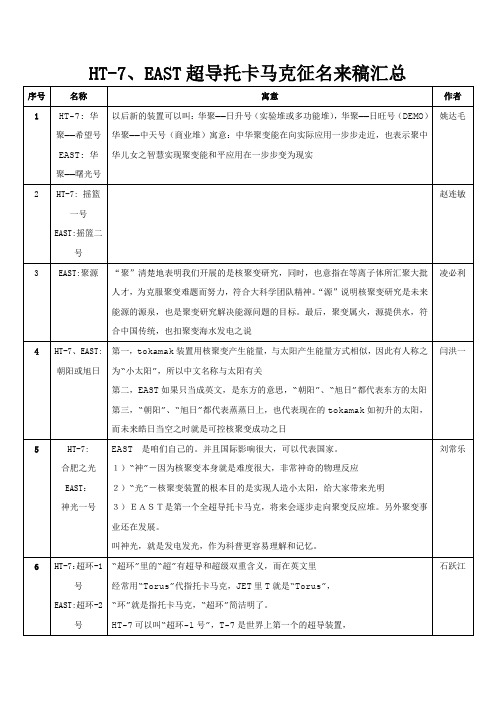
EAST可以叫“超环-2号”
石跃江
7
HT-7:起航
EAST:未来之星
代表第二代前沿的受控核聚变的研究装置
胡燕兰
8
HT-7:红心1号
EAST:红心2号
红心在现代比喻忠于革命事业的思想,寓意我所职工的壮志豪情。也寓意我所聚变能源的研究志向于为国家为未来,祖国建设加注推力的理想。红心也指靶子的正中心,寓意我所科研的最终目标,箭指实现新能源利用的中心。红心的现实意义相当于我们核聚变装置内部的超高温度,它是炽热的,给人的意识形态就是火红,与我们的EAST,HT-7有着神行相似的特点。红心也音同“宏心”,两心交叉,是一种激情。红心1号,2号的接延,更使得我们未来的研究有延续性,寓意红心不灭。
李高云
26
HT-7:合肥托7
EAST:东方快导
李柱
27
HT-7、EAST:合肥星源
聚变能是太阳等恒星的能量的来源
韦江龙
28
HT-7、EAST:超磁束能器
超----有先进、一流、超级、不凡等最前沿的意思,又能表现超导、超大电流、超强磁场、超高温、超低温、超高真空等极限环境的意思,磁---是聚变最基本又是唯一实现能量约束控制的手段。束---有约束、控制,受控,甚至有聚的意思,和束能连读就是约束或控制能量的意思,这里当然指约束控制聚变能量的意思,能----能量、能源、---是聚变最终极的目标,也是聚变的主题。束能正是我们现在、将来需要做并且必须要实现的控制技术。器-----是任一复杂紧凑装置的通称,很多最先进的产品都用器来表达,科幻、卡通也喜欢用器来表达一些来往与太空、水下、陆地的装置。[超磁束能器]将聚变工程的材料、方式方法、技术手段、工程形体、工程意义与目标基本上都概括了,具有专业深意与通俗易懂,语句顺畅。也能表现我们做的聚变工程是有着超强的积聚人才的事业。
- 1、下载文档前请自行甄别文档内容的完整性,平台不提供额外的编辑、内容补充、找答案等附加服务。
- 2、"仅部分预览"的文档,不可在线预览部分如存在完整性等问题,可反馈申请退款(可完整预览的文档不适用该条件!)。
- 3、如文档侵犯您的权益,请联系客服反馈,我们会尽快为您处理(人工客服工作时间:9:00-18:30)。
a rXiv:as tr o-ph/62417v315Aug26CORONA OF MAGNETARSAndrei M.Beloborodov 1Physics Department and Columbia Astrophysics Laboratory,Columbia University,538West 120th Street New York,NY 10027;amb@ Christopher Thompson Canadian Institute for Theoretical Astrophysics,University of Toronto,60St.George Street,Toronto,ON M5S 3H8,Canada;thompson@cita.utoronto.ca ABSTRACT We develop a theoretical model that explains the formation of hot coronae around strongly magnetized neutron stars —magnetars.The starquakes of a magnetar shear its external magnetic field,which becomes non-potential and is threaded by an electric current.Once twisted,the magnetosphere cannot untwist immediately because of its self-induction.The self-induction electric field lifts particles from the stellar surface,accelerates them,and initiates avalanches of pair creation in the magnetosphere.The created plasma corona maintains the electric current demanded by curl B and regulates the self-induction e.m.f.by screening.This corona persists in dynamic equilibrium:it is continually lost to the stellar surface on the light-crossing time ∼10−4s and replen-ished with new particles.In essence,the twisted magnetosphere acts as an accelerator that converts the toroidal field energy to particle kinetic ing a direct nu-merical experiment,we show that the corona self-organizes quickly (on a millisecond timescale)into a quasi-steady state,with voltage e Φe ∼1GeV along the magnetic lines.The voltage is maintained near threshold for ignition of pair production,and pair production occurs at a rate just enough to feed the electric current.The heating rateof the corona is ∼1036erg/s,in agreement with the observed persistent,high-energy output of magnetars.We deduce that a static twist that is suddenly implanted into the magnetosphere will decay on a timescale of 1-10yrs.The particles accelerated in the corona impact the solid crust,knock out protons,and regulate the column density of the hydrostatic atmosphere of the star.The transition layer between the atmosphere and the corona may be hot enough to create additional e ±pairs.This layer is the likely source of the observed 100keV emission from magnetars.The corona emits curvature radiation up to 1014Hz and can supply the observed IR-optical luminosity.We outline the implications of our results for the non-thermal radiation in other bands,and for the post-burst evolution of magnetars.Subject headings:plasmas—stars:coronae,magneticfields,neutron—X-rays:stars1.INTRODUCTIONAt least10%of all neutron stars are born as magnetars,with magneticfields B>1014G. Their activity is powered by the decay of the ultrastrongfield and lasts about104years.They are observed at this active stage as either Soft Gamma Repeaters(SGRs)or Anomalous X-ray Pulsars(AXPs)(see Woods&Thompson2006for a recent review).Twelve active magnetars are currently known,and all of them have similar parameters:spin period P∼10s,persistent X-ray luminosity L∼1035−1036erg/s,and surface temperature k B T∼0.5keV.The large-scale (dipole)component of the magneticfield B dipole>1014G has been inferred from the measurement of rapid spindown in several AXPs,and more recently in two SGRs(Kouveliotou et al.1998, 1999).However,there is evidence for even stronger magneticfield inside the star,as was originally deduced from considerations of magneticfield transport(Thompson&Duncan1996).In particular, the occurence of enormously energetic X-rayflares in SGRs points to internal magneticfields approaching∼1016G(Hurley et al.2005).Bursting activity has also been detected in two AXPs(Kaspi et al.2003),which strongly supports the hypothesis that active rearrangement of the magneticfield takes place in AXPs as well as SGRs,although at differing rates.Besides the sporadic X-ray outbursts,a second,persistent,form of activity has been discovered by studying the emission spectra of magnetars.Until recently,the spectrum was known to have a thermal component with temperature k B T∼0.5keV,interpreted as blackbody emission from the star’s surface.The soft X-ray spectrum also showed a tail at2−10keV with photon index Γ=2−4.Intriguingly,the hardness of the2−10keV spectrum correlates with long-term activity as a transient burst source(Marsden&White2001).This deviation from pure surface emission already suggested that energy is partially released above the star’s surface.Recently, observations by RXTE and INTEGRAL have revealed even more intriguing feature:magnetars are bright,persistent sources of100keV X-rays(Kuiper et al.2004;Molkov et al.2005;Mereghetti et al.2005;den Hartog et al.2006;Kuiper et al.2006).This high-energy emission forms a separate component of the magnetar spectrum,distinct from the soft X-ray component that was known before.The new component becomes dominant above10keV,has a very hard spectrum,Γ≃1,and peaks above100keV where the spectrum is unknown.The luminosity in this band, L∼1036erg s−1,even exceeds the thermal luminosity from the star’s surface.These hard X-rays can be emitted only in the exterior of the star and demonstrate the presence of an active plasma corona.Our goal in this paper is to understand the origin and composition of the magnetar corona.The starting point of our analysis is the fact that an evolving magnetar experiences strong deformations of its crust,due to a shifting configuration of the internal magneticfield.These“starquakes”shear the magneticfield that is anchored in the crust,thereby injecting an electric current into the stellar magnetosphere.This process bears some resemblence to the formation of current-carryingstructures in the Solar corona,although there are important differences which shall be discussed below.We investigate how the starquakes and twisting of the magnetosphere can lead to the formation of a plasma corona around a magnetar.The persistence of magnetospheric twists can explain several observed properties of the AXPs and SGRs(Thompson,Lyutikov,&Kulkarni2002;hereafter TLK).TLK investigated the obser-vational consequences using a static,force-free model,idealizing the magnetosphere as a globally twisted dipole.They showed that a twist affects the spindown rate of the neutron star:it causes the magnetosphere toflare out slightly from a pure dipole configuration,thereby increasing the braking torque acting on the star.The force-free configuration is independent of the plasma behavior in the magnetosphere.It does rely,however,on the presence of plasma that can conduct the required current j B=(c/4π)∇×B.This requires a minimum density n c=j B/ec.TLK showed that even this minimum density significantly modifies the stellar radiation by multiple resonant scattering, which can explain the tail of the surface emission at2−10keV.In this paper,we formulate the problem of plasma dynamics in the closed twisted magneto-sphere andfind a simple solution to this problem,which allows one to understand the observed energy output of the magnetar corona and the evolution of magnetic twists.Plasma behavior around neutron stars has been studied for decades in the context of radio pulsars,and that prob-lem remains unsolved.The principle difference with radio pulsars is that their activity is caused by rotation,and dissipation occurs on open magnetic lines that connect the star to its light cylinder. Electron-positron pairs are then created on openfield lines(e.g.Ruderman&Sutherland1975; Arons&Scharlemann1979;Harding&Muslimov2002).By contrast,the formation of a corona around a magnetar does not depend on rotation of the neutron star.All observed magnetars are slow rotators(Ω=2π/P∼1Hz),and their rotational energy cannot feed the observed coronal emission.(The bolometric output of some magnetars is∼104times larger than the spindown luminosity,as deduced from the rotational period derivative!)The openfield lines form a tiny fraction R NSΩ/c∼3×10−5of the magneticflux threading the neutron star.Practically the entire plasma corona is immersed in the closed magnetosphere and its heating must be caused by some form of dissipation on the closedfield lines.In contrast with canonical radio pulsars,the magnetar corona admits a simple solution.Plasma near a neutron star is strongly constrained compared with many other forms of plasma encountered in laboratory and space,and therefore easier to model.The relative simplicity is due to the fact that the magneticfield is strong andfixed—its evolution timescale is much longer than the residence time of particles in the corona.Furthermore,particles are at the lowest Landau level and move strictly along the magneticfield lines,which makes the problem effectively one-dimensional.Finally,the magnetic lines under consideration are closed,with both ends anchored in the highly conducting stellar material.The basic questions that one would like to answer are as follows.How is the magnetosphere populated with plasma?The neutron star surface has a temperature k B T<∼1keV and the scale-height of its atmospheric layer(if it exists)is only a few cm.How is the plasma supplied above this layer and what type of particles populate the corona?How is the corona heated,and what are the typical energies of the particles?If the corona conducts a current associated with a magnetic twist∇×B=0,how rapid is the dissipation of this current, i.e.what is the lifetime of the twist?Does its decay imply the disappearance of the corona?An outline of the model proposed in this paper is as follows.The key agent in corona formation is an electricfield E parallel to the magneticfield.E is generated by the self-induction of the gradually decaying current and in essence measures the rate of the decay.It determines the heating rate of the corona via Joule dissipation.If E =0then the corona is not heated and,being in contact with the cool stellar surface,it will have to condense to a thin surface layer with k B T<∼1keV.The current-carrying particles cannotflow upward against gravity unless a force eE drives it.On the other hand,when E exceeds a critical value,e±avalanches are triggered in the magnetosphere,and the created pairs screen the electricfield.This leads to a“bottleneck”for the decay of a magnetic twist,which implies a slow decay.The maintenance of the corona and the slow decay of the magnetic twist are intimately related because both are governed by E .In order tofind E ,one can use Gauss’law∇·E=4πρ,where ρis the net charge density of the coronal plasma.This constraint implies that E andρmust be found self-consistently.We formulate the problem of plasma dynamics in a twisted magneticfield and the self-consistent electricfield,and investigate its basic properties.The problem turns out to be similar to the classical double-layer problem of plasma physics(Langmuir1929)with a new essential ingredient:e±pair creation.We design a numerical experiment that simulates the behavior of the1-D plasma in the mag-netosphere.The experiment shows how the plasma and electricfield self-organize to maintain the time-average magnetospheric current¯j=j B demanded by the magneticfield,(4π/c)¯j=∇×B. The electric current admits no steady state on short timescales and keepsfluctuating,producing e±avalanches.This state may be described as a self-organized criticality.Pair creation is found to provide a robust mechanism for limiting the voltage along the magnetic lines to eΦe 1GeV and regulate the observed luminosity of the corona.The paper is organized as follows.We start with a qualitative description of the mechanism of corona formation,and show that it can be thought of as an electric-circuit problem(§2).A careful formulation of the circuit problem and the set up of numerical experiment are described in§3. In§4wefind that the circuit without e±creation does not provide a self-consistent model.Pair creation is found to be inevitable and described in detail in§5.In§6we discuss the transition layer between the corona and the relatively cold surface of the star.The maintenance of a dense plasma layer on the surface is addressed in§7.Observational implications and further developments of the model are discussed in§8.2.MECHANISM OF CORONA FORMATION2.1.Ejection of Magnetic Helicity from a Neutron StarA tightly wound-up magneticfield is assumed to exist inside magnetars(e.g.Thompson& Duncan2001).The internal toroidalfield can be much stronger than the external large-scale dipole component.1The essence of magnetar activity is the transfer of magnetic helicity from the interior of the star to its exterior,where it dissipates.This involves rotational motions of the crust, which inevitably twist the external magnetosphere that is anchored to the stellar surface.The magnetosphere is probably twisted in a catastrophic way,when the internal magneticfield breaks the crust and rotates it.Such starquakes are associated with observed X-ray bursts(Thompson& Duncan1995).The most interesting effect of a starquake for us here is the partial release of the winding of the internal magneticfield into the exterior,i.e.,the injection of magnetic helicity into the magnetosphere.Since the magneticfield is energetically dominant in the magnetosphere,it must relax there to a force-free configuration with j×B=0.The effective footpoints of the force-freefield lines sit in the inner crust of the star.At this depth currents mayflow across the magnetic lines because the deep crust can sustain a significant Amp`e re force j×B/c=0:this force is balanced by elastic forces of the deformed crust.The ability of the crust to sustain j∦B quickly decreases toward the surface,and it is nearly force-free where2ρ<∼1013B2.515g/cm3(Thompson&Duncan2001).The build-up of stresses in the crust from an initial magnetostatic equilibrium has been studied recently by Braithwaite&Spruit(2006).The ejection of helicity may be thought of as directing an interior current(which previously flowed across thefield and applied a j×B/c force)into the force-free magnetosphere.The ejected currentflows along the magnetic lines to the exterior of the star,reaches the top of the line and comes back to the star at the other footpoint.The currents emerging during the starquake may percolate through a network of fractures in the crust.Then large gradients in thefield are initially present which can be quickly erased.A relatively smooth magnetospheric twist of scale∼R NS will have the longest lifetime.Globally twisted magneticfields are observed to persist in the Solar corona over many Alfv´e n crossing times.Twisted magnetic configurations have also been studied in laboratory experiments. In particular,the toroidal pinch configuration has been studied in detail and is well explained as a relaxed plasma state in which the imparted magnetic helicity has been nearly conserved(Taylor 1986).The toroidal pinch relaxes to the minimum-energy state which has a uniform helicity density:∇×B=µB withµ=const.This state is achieved because the experiment has toroidal geometry and the current is isolated from an external conductor.The relaxation process is then free to redistribute the current between neighboring magneticflux tubes via small-scale reconnection, which leads to a uniformµ.The geometry is different in the case of a magnetar(or the sun)—the field lines are anchored to the star and their configuration depends on the footpoint motion(for related calculations of the relaxed state of a driven plasma see,e.g.,Tang&Boozer[2005]).The long lifetime(>∼1year)of a twisted configuration around magnetars is supported by observations of long-lived changes in the spindown rate and X-ray pulse profiles(Woods&Thompson2006; TLK)as well as persistent nonthermal X-ray emission.The shape of a twisted force-free magnetosphere may be calculated given the boundary condi-tions at the footpoints.An illustrative model of a globally twisted dipolefield was considered by TLK.It has one parameter—twist angle∆φ—and allows one to see the qualitative effects of increasing twist on the magnetic configuration.The current density in this configuration isj(r,θ)=c4πrsin2θ∆φ(r>R NS),(1)where r,θ,φare spherical coordinates with the polar axis chosen along the axis of the dipole.Evenfor strong twists,∆φ∼1,the poloidal components B r and Bθare found to be close to the normaldipole configuration,although the magnetosphere is somewhat inflated.The main difference is theappearance of a toroidalfield Bφ.The global structure of a real twisted magnetosphere may be complex.The displacementξof the magnetosphere’s footpoints during a starquake may be described as a2D incompressiblemotion with∇·ξ=0and∇×ξ=0.Suppose that the yielding behavior of the crust produces amotionξ=0that is localized within a plate S,and this plate is connected by magnetosphericfieldlines to another plate on the opposite side of the star.Then ∇×ξd S= ξ·d L=0where L is the boundary of S.Hence∇×ξmust change sign within S.For example,for an axially symmetricrotational motion,the ejection of current in the center of the plate is accompanied by initiation ofan opposite current on its periphery that screens the ejected current from the unmoved footpointswithξ=0.In this paper,we study the plasma dynamics in aflux tube dS with a given twist currentj B=(c/4π)|∇×B|.The magnetosphere may be thought of as a collection of such elementaryfluxtubes,whose currents j B vary from footpoint to footpoint.The variation of j B is expected to begradual,so that the characteristic thickness of aflux tube with a given j B is comparable to R NS.The emerging currents are easily maintained during the X-ray outburst accompanying a star-quake.A dense,thermalized plasma is then present in the magnetosphere,which easily conductsthe current.Plasma remains suspended for some time after the starquake because of the transientthermal afterglow with a high blackbody temperature,up to∼4keV.The cyclotron resonance ofthe ions is at the energy eB/m p c=6.3B15keV and,during the afterglow,the radiativeflux atthe resonance is high enough to lift ions from the surface against gravity(Ibrahim et al.2001).Eventually the afterglow extinguishes and the radiativeflux becomes unable to support the plasma outside the star.The decreasing density then threats the capability of the magnetosphere to conduct the current of the magnetic twist.A minimal“corotation”charge densityρco=−Ω·B/2πc is always maintained because of rotation of the star with frequencyΩ(Goldreich&Julian1969), but it is far smaller than the minimal density that is needed to supply the current j(eq.1):|ρco|∆φ ΩR maxL ∼I2∂t B24π ,(4)as follows from Maxwell’s equations with E≪B(ndau&Lifshitz1975).Thefirst term on the right-hand side is the Joule dissipation caused by E .The second term—the divergence of the Poyntingflux—describes the redistribution of magnetic energy in space.The decay of the twist is related to the voltage between the footpoints of a magnetic line,Φe= C A E·d l.(5)Fig.1.—Schematic picture of a current-carrying closed magneticflux tube,anchored to the star’s surface.The current is initiated by a starquake that twists one(or both)footpoints of the tube. The currentflows along the tube into the magnetosphere and returns to the star at the other footpoint,where it enters the atmosphere and the crust,following the magneticfield lines(j B). Sufficiently deep in the crust,the current canflow across thefield lines and change direction,so that it canflow back to the twisted footpoint through the magnetosphere(or directly through the star,depending on the geometry of the twist).A self-induction voltage is created along the tube between its footpoints,which accompanies the gradual decay of the current.The voltage is generated because the current has a tendency to become charge-starved above the atmospheric layer whose scale-height h=k B T/gm p is a few cm.Here A and C are the anode and cathode footpoints and d l is the line element;the integral is taken along the magnetic line outside the star(Fig.1).The productΦe I approximately represents the dissipation rate˙E in the tube.(The two quantities are not exactly equal in a time-dependent circuit.)The instantaneous dissipation rate is given by˙E= C A E·I(l)d l,(6) where I(l)=S j is the instantaneous current at position l in the tube.The current isfixed at the footpoints A and C,I=I0;it may,however,fluctuate between the footpoints.Note that the true scalar potentialΦis different fromΦe and not related to the dissipation rate.Φis the0-component of the4-potentialΦµ=(Φ,A)which is related to the electricfield byE=−∇Φ−1∂t.(7)If anode and cathode are connected by an ideal conductor thenΦ(C)−Φ(A)=0while the voltage Φe may not vanish.The voltageΦe is entirely maintained by the self-induction that accompanies the gradual untwisting of the magneticfield.Thus,Φe reflects the gradual decrease of the magnetic helicity in the tube,˙H=∂which can accelerate particles to the Lorentz factorγ±sufficient to ignite e±creation.A third possible source—thermal e±production in a heated surface layer—will be discussed in§6;the corresponding minimum voltage is currently unknown.IfΦe is too low and the plasma is not supplied,aflux tube is guaranteed to generate a stronger electricfield.The current becomes slightly charge-starved:that is,the net density of free charges becomes smaller than|∇×B|/4πe.The ultrastrong magneticfield,whose twist carries an enormous energy compared with the energy of the plasma,does not change and responds to the decrease of j by generating an electricfield:a small reduction of the conduction current j induces a displacement current(1/4π)∂E/∂t=(c/4π)∇×B−j.The longitudinal electricfield E then quickly grows until it can pull particles away from the stellar surface and ignite pair creation.The limiting cases E →0(no decay of the twist)and E →∞(fast decay)both imply a contradiction.The electricfield and the plasma content of the corona must regulate each other toward a self-consistent state,and the gradual decay of the twist proceeds through a delicate balance:E must be strong enough to supply plasma and maintain the current in the corona; however,if plasma is oversupplied E will be reduced by screening.A cyclic behavior is possible, in which plasma is periodically oversupplied and E is screened.Our numerical experiment will show that such a cyclic behavior indeed takes place.3.ELECTRIC CIRCUIT3.1.Basic PropertiesThree facts facilitate our analysis of plasma dynamics in the electric circuit of magnetars:1.The ultrastrong magneticfield makes the particle dynamics1-D.The rest-energy density of the coronal plasma is∼mcj/e,where m is the mass of a plasma particle.It is much smaller than the magnetic energy density B2/8π:their ratio is∼mc2/eBR NS∼10−15(m/m p)B−115.The magneticfield lines are not perturbed significantly by the plasma inertia,and they can be thought of asfixed“rails”along which the particles move.The particle motion is confined to the lowest Landau level and is strictly parallel to thefield.2.The particle motion is collisionless in the magnetosphere.It is governed by two forces only: the component of gravity projected onto the magneticfield and a collective electricfield E which is determined by the charge density distribution and must be found self-consistently.3.The star possesses a dense and thin atmospheric layer.4Near the base of the atmosphere, the required current j B=(c/4π)∇×B is easily conducted,with almost no electricfield.Therefore the circuit has simple boundary conditions:E =0andfixed current.The atmosphere is muchthicker than the skin depth of the plasma and screens the magnetospheric electricfield from the star.Our goal is to understand the plasma behavior above the screening layer,where the atmospheric density is exponentially reduced and an electricfield E must develop.The induced electricfield E and conduction current j satisfy the Maxwell equation,∇×B=4πc∂E∂t =4π(j B−j),j B≡cτ∼4πj B.(13)The current j=env(carried by particles with charge e and mass m)responds to the induced E by changing v,vm.(14) From equations(13)and(14)we get1m=ω2P.(15) Thus the timescale of the current response to deviations of j from j B is simply the Langmuir plasma timescaleω−1P,which is very short.Taking the characteristic density of the corona,n∼n c≡j Bcreate an electricfield E∼eδN c/R2NS>GMm p/eR2NS that easily pulls out the missing charges from the surface.Adopting a characteristic velocity v∼c of the coronal particles,the Debye length of the plasma λD=v/ωP is essentially the plasma skin depth c/ωP.An important physical parameter of the corona is the ratio of the Debye length to the circuit size L∼R NS.ζ=λDLωP.(17)In the case of the twisted dipolar magnetosphere(eq.[1]),this becomesζ=3×10⁻⁹B−1/215 ∆φsin2θ −1/2.(18) The same parameter may be expressed using a dimensionless current j B/j∗∼1017B15∆φsin2θ. Here j∗corresponds to the plasma density n∗=j∗/ec such thatλD=L,j B4πeL2.(19) Note that equation(15)for the plasma frequency is valid only for non-relativistic plasma.We will use the above definition ofωP,however,one should keep in mind that plasma oscillations in the corona may have a smaller frequency because of relativistic effects.3.2.Quasi-Neutral Steady State?Suppose for now that no e±are created in the corona,so that the circuit must be fed by charges lifted from the stellar surface.May one expect that a steady current j=j B is maintained in the neutral corona by a steady electric force eE ∼gm i or eE ∼gm e?It turns out that such a balance between gravitational and electric forces is impossible in the circuit for the following reason:E exerts opposite forces on positive and negative charges while the force of gravity has the same sign.This precludes a steady state where E lifts particles into the magnetosphere without a significant deviation from neutrality appearing somewhere in the circuit.The point is illustrated by the following toy model.Suppose positive charges e(mass m+)flow with velocity v+>0and negative charges−e(mass m−)flow with velocity v−<0.Theflow of each species is assumed to be cold in this illustration, with a vanishing velocity dispersion at each point,and the total current is j=j++j−where j±=±en±v±.The continuity equation for+/−charges reads∂(±en±/B)∂l=0,(20) where l is the coordinate along thefield line.Suppose the circuit is steady,∂/∂t=0,and no strong deviation from neutrality occurs,i.e.n+≃n−everywhere.Then onefinds j+/j i=−v+/v−=const,that is the ratio of velocities must remain constant along thefield line.Hence v+and v−must both vanish at the footpoints.This cannot be:for example,at the anode E must lift ions against gravity,and hence it is accelerating the electrons downward rather than stopping them5 So,if the current-carrying particles are supplied by the star,we expect either a significant charge separation at some places in the circuit,or a time-dependent behavior(or both).One must also allow for the creation of e±pairs if the light charges are accelerated to high enough energies, which will be discussed in§5.Our approach to this problem is a direct numerical experiment that simulates the time-dependent behavior of plasma particles in the circuit.3.3.Numerical Simulation of a One-Dimensional CircuitWe shall describe below a time-dependent simulation of a circuit operating along a thin mag-netic tube with given j B=(c/4π)|∇×B|that isfixed in time.Strictly speaking,j B is quasi-steady: it will be found to decay on a long resistive timescale(∼yrs),much longer than the dynamic time of the current t dyn=L/c∼10−4s.The purpose of the simulation is to understand how plasma is supplied above the star’s surface layer,and tofind the electricfield that develops along the tube.The electricfield may be decomposed as E=E +E⊥where E is parallel to the magnetic field.It is E that governs the plasma motion and determines the release of magnetic energy in the circuit.In thefixed magnetic configuration,∇×B does not vary with time and remains parallel to B(the force-free condition).Then equation(11)implies that∂E/∂t is parallel to B,i.e.no perpendicularfield E⊥is created by the induction effect,and∇·E⊥=0may be assumed.Then Gauss’law readsd E4πρ=∇·E =5A static plasma configuration is possible with the electric and gravitational forces balancing each other at each point of the circuit.However,j=0in this configuration and it is not relevant to our circuit problem.Besides,such a configuration would be unstable.。