Reflection and refraction of attenuated waves at boundary of elastic solid and porous solid sat
电磁波屏蔽材料

电磁波屏蔽材料Electromagnetic Wave Shielding Materials。
With the rapid development of modern technology, electromagnetic waves have become an indispensable part of our daily lives. However, the increasing exposure to electromagnetic radiation has raised concerns about its potential health effects. Therefore, the demand for electromagnetic wave shielding materials has been increasing.Electromagnetic wave shielding materials are used to reduce the penetration of electromagnetic waves into a specific area. These materials can be classified into two types: conductive and non-conductive. Conductive materials, such as metals and conductive polymers, can reflect and absorb electromagnetic waves. Non-conductive materials, such as ceramics and glasses, can attenuate electromagnetic waves by scattering and absorbing them.Metals, such as copper, aluminum, and silver, are commonly used in electromagnetic wave shieldingapplications due to their high conductivity and excellent shielding effectiveness. However, metals have some disadvantages, such as weight, corrosion, and difficulty in processing. Therefore, researchers have been exploring alternative materials that can provide comparable shielding effectiveness with lower weight and cost.Carbon-based materials, such as carbon nanotubes, graphene, and carbon fibers, have attracted much attention as potential electromagnetic wave shielding materials due to their high conductivity, light weight, and excellent mechanical properties. Carbon nanotubes are cylindrical tubes made of carbon atoms and have a high aspect ratio, which makes them efficient in absorbing electromagnetic waves. Graphene is a two-dimensional material made of a single layer of carbon atoms arranged in a hexagonal lattice. It has high electrical conductivity and can be easily processed into various shapes. Carbon fibers are made of carbon atoms and have high tensile strength and stiffness. They can be woven into fabrics and used aselectromagnetic wave shielding materials.Polymer-based materials, such as conductive polymers and polymer composites, have also been extensively studied as electromagnetic wave shielding materials. Conductive polymers are organic materials that have both electrical conductivity and flexibility. They can be easily processed into various shapes and have good compatibility with other materials. Polymer composites are made by embedding conductive fillers, such as metal particles and carbon-based materials, into polymer matrices. They can provide a balance between shielding effectiveness, weight, and cost.Ceramics and glasses are non-conductive materials that can attenuate electromagnetic waves by scattering and absorbing them. They are commonly used in high-frequency applications, such as microwave ovens, radar systems, and electronic devices. Ceramics, such as alumina and zirconia, have high dielectric constants and can absorb electromagnetic waves by polarization. Glasses, such as borosilicate and soda-lime, have low dielectric constants and can scatter electromagnetic waves by refraction andreflection.In conclusion, electromagnetic wave shielding materials play an important role in protecting human health and electronic devices from the harmful effects of electromagnetic radiation. The choice of shielding materials depends on the specific application requirements, such as frequency range, shielding effectiveness, weight, and cost. With the continuous development of new materials and technologies, the future of electromagnetic wave shielding materials looks promising.。
PartV.Optics第五部光学
30.1. Reflection 反射
Conductor: E of light drives e to oscillate re-radiate reflection
導體:光的 E 驅使 e 擺動 再輻射 反射
parallel to its incident direction.
請証明任何在紙面上的入射光線,反射後都與入射方向反平行。
Ray turned by angle A here 光射在此的轉角為 A
Ray turned by angle B here 光射在此的轉角為 B
A 2
A B 180
折射
nc v
index of refraction 折射率
Observers at A & B count same number of wave crests at any given duration 在 A 和 B 處的觀察者在任何時段中數到的波峯數目都一樣
wave frequency doesn’t change in crossing media. 波的頻率在跨越介質後保持不變。
v c
f nf
smaller for medium with slower v or higher . 在 v 較慢或 n 較大的介質中較小。
Table 30.1. Indices of Refraction
1
1
1
1
v1 t v2 t
2
sin1 sin 2
Example 30.1. The Corner Reflector 角落反射器
专业英语期末复习

The law of reflection applies to both flat and curved surfaces. For a curved surface, the angle of reflection is determined by the angle of incidence between the incident ray and the surface normal at the point where the incident ray strikes the surface.
像差可以通过组合具有适当的曲率半径的不同球面而被减小,但却不能完 全消除。
However, to reduce aberrations of this kind to an acceptable level for optical instruments such as microscopes, binoculars, or cameras, each lens must be made of several thin lenses in combination. (选择)
Chapter 3. Optical Instruments
1.2 Reflection and Refraction(定义、选择)
The normal, the incident ray, and the reflected ray all lie in a plane perpendicular to the reflecting surface, known as the plane of incidence. The light ray does not “turn” out of the plane of incidence as it is reflected.
工程光学英语
Axial magnification (longitudinal magnification) is defined as the ratio of a short length, or depth, in the image measured along the axis, to the conjugate length in the object. In the air, it is equal to the square of the transverse magnification.
upright or inverted, real or virtual) 8. Concave and convex mirror
7
Some Concept
1. Vertex is the point where the optic intersects the surface.
2. Object distance is the distance from vertex to the object.
2
4. The Law of Refraction
The angle made by the incident ray, that made by the refracted ray, and the surface normal at the point of incidence in a refractive process obey the expression
Light field techniques for reflections and refractions
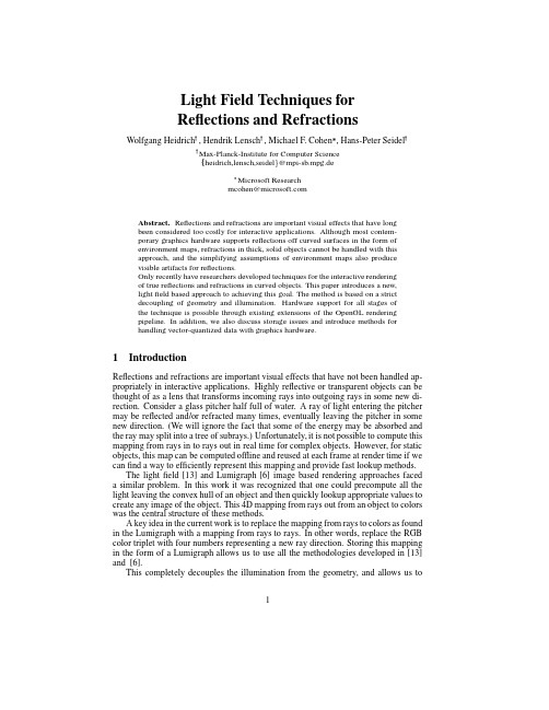
Light Field Techniques forReflections and RefractionsWolfgang Heidrich,Hendrik Lensch,Michael F.Cohen,Hans-Peter SeidelMax-Planck-Institute for Computer Scienceheidrich,lensch,seidel@mpi-sb.mpg.deMicrosoft Researchmcohen@Abstract.Reflections and refractions are important visual effects that have longbeen considered too costly for interactive applications.Although most contem-porary graphics hardware supports reflections off curved surfaces in the form ofenvironment maps,refractions in thick,solid objects cannot be handled with thisapproach,and the simplifying assumptions of environment maps also producevisible artifacts for reflections.Only recently have researchers developed techniques for the interactive renderingof true reflections and refractions in curved objects.This paper introduces a new,lightfield based approach to achieving this goal.The method is based on a strictdecoupling of geometry and illumination.Hardware support for all stages ofthe technique is possible through existing extensions of the OpenGL renderingpipeline.In addition,we also discuss storage issues and introduce methods forhandling vector-quantized data with graphics hardware.1IntroductionReflections and refractions are important visual effects that have not been handled ap-propriately in interactive applications.Highly reflective or transparent objects can be thought of as a lens that transforms incoming rays into outgoing rays in some new di-rection.Consider a glass pitcher half full of water.A ray of light entering the pitcher may be reflected and/or refracted many times,eventually leaving the pitcher in some new direction.(We will ignore the fact that some of the energy may be absorbed and the ray may split into a tree of subrays.)Unfortunately,it is not possible to compute this mapping from rays in to rays out in real time for complex objects.However,for static objects,this map can be computed offline and reused at each frame at render time if we canfind a way to efficiently represent this mapping and provide fast lookup methods.The lightfield[13]and Lumigraph[6]image based rendering approaches faced a similar problem.In this work it was recognized that one could precompute all the light leaving the convex hull of an object and then quickly lookup appropriate values to create any image of the object.This4D mapping from rays out from an object to colors was the central structure of these methods.A key idea in the current work is to replace the mapping from rays to colors as found in the Lumigraph with a mapping from rays to rays.In other words,replace the RGB color triplet with four numbers representing a new ray direction.Storing this mapping in the form of a Lumigraph allows us to use all the methodologies developed in[13] and[6].This completely decouples the illumination from the geometry,and allows us to1exchange the environment and the refracting/reflecting object independently of eachother.Such a separation also has the advantage that some extra blurring for the indirectillumination will in most cases be tolerable since direct illumination is visually muchmore important than indirect illumination for almost all scenes.This means that onecan get away with a lower resolution lightfield,which saves memory and reduces theacquisition cost.After a discussion of previous work,wefirst introduce some notation for lightfields,and then describe our technique for rendering reflections and refractions in Section4.We then turn to the hardware rendering of vector-quantized lightfields[13]in Section5, and discuss our approaches in Section6.2Previous WorkProducing approximate reflections and refractions at interactive rates has been donewith environment maps[2].The inherent assumption is that what is seen in a reflectionis sufficiently far away from the reflector.This assumption breaks down in many scenes.Environment maps can also be used for refractions at thin surfaces.A thin surface isone,for which the thin lens approximation holds(see[3]).This approximation assumesthat the entry and exit points of each ray coincide.It does not hold for objects like glassballs,but it can be used for windows or spectacle lenses.Only recently have researchers started to develop algorithms that do not have theserestrictions.A commonly used technique for rendering mirror reflections in planar objects is given in[5]:with a simple affine model/view matrix,the scene is mirrored atthe planar reflector.This mirrored scene is rendered at every pixel where the reflectoris visible in the current view.It is possible to realize multiple reflections by repeatingthis process as explained in[5].For curved objects the geometric transformations yielding the reflected geometryare more complex.Rather than transforming the complete object with a single affinetransformation,a different transformation is required for each point on the reflectedobject.In[16]an algorithm is introduced,in which all vertices of the reflected geometryare individually transformed in software.This approach only works at interactive framerates for relatively smooth objects that are either concave or convex.As mentioned above,the lightfield[13]and Lumigraph[6]approaches are based on a dense sampling of the plenoptic function[1],which describes theflow of light ina scene.This way,the lightfield outside the convex hull of an object in empty spacecan be represented as a4-dimensional function in the parameters,,,and.The parameterization of this function is a topic of ongoing research[4],but typically the2-plane parameterization explained in Section3is used[6,13].The advantage of thelightfield approach is that images of the scene from new camera positions can simply becomputed by interpolating radiance values in4dimensions.This is a very inexpensiveoperation that can be further accelerated through the use of OpenGL-compliant graphicshardware,as has been shown in[6]and[19].The disadvantage of this method is that it involves large memory requirements tostore the4D data structures.A lightfield of moderate resolution can easily have a size of multiple Gigabytes.The authors of[13]have proposed to use vector quantization (VQ)to compress the data.VQ has some interesting advantages over other compres-sion methods that make it attractive for compressing lightfields.Firstly,decompression is a constant time operation,and secondly the different entries can be decompressed in-dependently of each other and in arbitrary order(random access).In Section5we describe how the hardware accelerated rendering algorithm for lightfields[6]can be2extended to the direct rendering of vector-quantized lightfields.This means that the lightfields do not have to be decompressed before hardware rendering,which is partic-ularly interesting since texture RAM is typically a scarce resource.The Lumigraph[6]extends the concept of a lightfield by adding some geometric information which helps compensating for artifacts that arise from the use of quadri-linear interpolation for the reconstruction.A coarse polygon mesh is stored together with the images.The mesh is used tofirstfind the approximate depth along the ray to be reconstructed,and then this depth is used to correct the weights for the interpolation. This depth corrected rendering can also be accelerated with graphics hardware[6].Miller[15]attempts to overcome blurring artifacts by introducing a parameteriza-tion in which the and parameters of the lightfield are the surface parameters of the reflecting object,and and parameterize the hemisphere of directions over the surface point.The authors call this a surface lightfield because the parameters are directly attached to the surface of the reflector.This is particularly well suited to mostly diffuse objects with well defined surface parameters.In addition to this different parameterization,[15]also introduces a block-based compression scheme which achieves higher compression ratios than VQ,but is also more complicated and requires the decompression of a complete block of values.This decompression has to be performed in software during the resampling process used for generating the texture maps.Both lightfield representations reach their limits when it comes to mirror reflections and narrow specular highlights from light sources.These will in both approaches still result in some amount of unwanted blurring,due to the limited resolution of the lightfield.This problem isfixed by another approach for using lightfields to render reflec-tions[14].There,the authors introduce the concept of image-based ray-tracing to render mirror reflections.In this work,a lightfield not only stores radiance values,but also geometric information such as depth and normal.The method proceeds by tracing rays through a lightfield of layered depth images[18].This method is computationally expensive and cannot be performed in real time on contemporary hardware.3Light FieldsOur work builds strongly on the lightfield[13],and the Lumigraph[6].A lightfield is a dense sampling of the5-dimensional plenoptic function[1],which describes the radiance at every point in space in every direction.Since radiance does not change along a ray in empty space(e.g.,outside the convex hull of an object),the dimensionality can be reduced by one,if an appropriate parameterization is found,that reflects this property.The so-called2-plane parameterization used by[13]and[6]representation fulfills this requirement.It represents a ray via its intersection points with two parallel planes. Since each of these points is characterized by two parameters in the plane,this results in a4-dimensional function that is sampled through a regular grid on each plane(see Fig.1).One useful property of the2-plane parameterization is that all the rays passing through a single point on the-plane form a perspective image of the scene,with the point being the center of projection.Thus,a lightfield can be considered a 2-dimensional array of images with eye points regularly spaced on the-plane.3Fig.1.A light field can be parameter-ized as a 2-dimensional array of images taken from a regular grid of eye pointson the-plane through a window on the-plane.Moreover,since we assume that the sam-pling is dense,the radiance along an arbi-trary ray passing through the two planes canbe interpolated from the known radiance val-ues in nearby grid points.Each such ray passesthrough one of the grid cells on the -plane and one on the -plane.These are bounded by four grid points on the respective plane,andthe radiance from any of the -points to any of the -points is stored in the data struc-ture.This makes for a total of 16radiance val-ues,from which the radiance along the ray can be interpolated quadri-linearly.As shown in [6],this can also be done in hardware.For each eye point on the -plane,the hardware rendering algorithm draws the grid cells surrounding the eye point using graphics hardware.The alpha values of the polygon ver-tices are set to 1at the eye point and to 0every-where else.Furthermore,each rendered poly-gon is textured with the -slice corresponding to the eye point,and these textures are weighted by the alpha values of the polygons.This combination of alpha blend-ing and texture mapping with bi-linear interpolation yields the desired reconstruction.1This hardware algorithms is many times faster than a purely software-based approach.For example,on an SGI O2the hardware renderer can achieve approximately 25frames per second in full screen resolution.This number is almost independent of light field resolution.The possibility to use graphics hardware for rendering is also what distinguishes the 2-plane parameterization from most other parameterizations that have been proposed for light fields (see,for example [4]).For us,this is the reason to use the 2-plane parameterization.4Decoupling Geometry and IlluminationAs stated above,the core of the proposed method is to separate the geometry and the illumination of an object into two distinct image-based data structures.The first data structure is a 2-plane parameterized “light field”containing a mapping from incoming rays to outgoing rays based on the geometry and refractive properties of the object.The outgoing rays are stored in the form of a color coded direction.The illumination corresponding to this outgoing ray can either be provided in the form of an environment map or in the form of another light field.Thus,to render a complete image,first the geometry light field is rendered,yielding an image of color coded ray directions.These can then be used to look up the illumina-tion from an environment map,to trace new rays into a scene,or lookup a color from a second light field describing the surrounding scene.When using environment maps,the geometry light field can directly contain the 2D texture coordinates for the entry in the environment map that corresponds to therefracted ray direction.The format for these values depends on the specific param-eterization used for the environment map.For example,for a spherical environment map[7],the texture coordinates are given as the and components of the normalized halfway vector between the refracted viewing ray and the-axis (see Fig.2).Fig.2.The texture coordinates that correspond to a certain ray direction in a spherical envi-ronment map are given by the normalized halfway vector between and the-axis(left).This is because a spherical map is the image of a small,reflective sphere as seen by an orthographic camera looking into the negative-axis.The vector corresponds to both the point on the sphere where is the reflection of,and to the sphere’s surface normal in that point.In our implementation we use the parabolic parameterization presented in[10].It has the advantage of providing a more uniform sampling of the hemisphere of direc-tions than the spherical parameterization,and the texture coordinates are less expensive to compute.The texture coordinates of the parabolic parameterization are given as and,which means that a simple division suffices to compute the texture coordinates instead of a vector normalization.While the advantage of a uniform sam-pling is essential,the performance benefits are not significant in our case.Independent of how the illumination is represented,thefirst step in the algorithm is the hardware-based rendering of the geometry lightfield as described in[6]and[19]. Afterwards,the framebuffer contains an image with the color coded texture coordinates for the environment map holding the illumination information.Now the framebuffer contents are read back to main memory and for each pixel the texture coordinates need to be used to look up the illumination from the environment map,before the resulting image is written back to the framebuffer,yielding thefinal image.The texture lookup can be achieved in one of the following two ways.Firstly,it can be performed in software.This is a relatively inexpensive operation,that is feasible even on low end platforms,as shown below.Alternatively,the graphics hardware can be employed for the texture lookup,using an extension that is available from SGI.The so-called pixel texture extension[17,8]modifies the rendering pipeline in such a way that the color values of the pixels in an image can be interpreted as texture coordinates, which are then in turn used to texture each individual pixel.This feature can be applied during so-called pixel transfer operations,that is,during the transfer of images to and from the framebuffer,and is exactly the functionality required for our algorithm.Al-though pixel textures are currently a proprietary extension from SGI,their usefulness is demonstrated by several applications,and will hopefully result in a more widespread availability of this extension.Fig.3shows images that were generated using this approach.The left image rep-5resents the color coded texture coordinates reconstructed from the geometry light field.The light field itself was generated using ray-tracing.Center and right represent the final result after the application of the environment map.This method is very fast,and achieves between 15and 20fps.on an Octane MXE using the pixel texture extension.The same images can be rendered with the software method at about 10frames per second on an SGI O2with a 175MHz R10k (images are of size pixels).Fig.3.Light fields rendering with decoupled geometry and illumination,the latter being provided through an environment map.Left:color coded texture coordinates for the environment map,as extracted from the geometry light field.Center/right:final renderings.4.1Illumination from Light FieldsInstead of using an environment map to store the illumination,it is also possible to use a second light field.The advantage of this approach is the additional dependency on the surface location,which allows for the proper handling of objects close to the refractor.As stated above,the use of environment maps for illumination is typically not of interest for implementing reflections.If the illumination is stored in light fields,however,the situation is different,because the near field effects that can be achieved with this method exceed the possibilities of traditional geometry-based rendering with environment maps.To store the illumination in a light field,the geometry light field has to contain the correct 4-dimensional ray direction ,,,and referencing into the illumination light field.The ray direction can be color coded into the R,G,B and A channels of the geometry light field.The exact coordinates,of course,again depend on the parameterization of the illumination light field.The rendering algorithm proceeds similarly to the case where the illumination is stored in an environment map.First,the geometry light field is rendered using hardware acceleration.Then,the framebuffer contents are read back to main memory.The ray lookup for determining the illumination is either performed in software,or using pixel textures and 4-dimensional texture mapping.The latter method will be described in more detail in Section 5.4.2Realistic MaterialsSo far,we have only considered either reflections or refractions,which is mandated by the fact that the geometry light field can only store either the coordinates for the reflec-tion or for the refraction part.However,it is possible to combine the two parts using multi-pass rendering,and also to develop models for more complicated materials,such as glossy reflections and the inclusion of a Fresnel term.These multi-pass techniques6have been introduced for geometry-based rendering in[11]and[9],but they directlytranslate to the image-based rendering techniques presented in this paper.Please referto the listed publications for the details.Fig.4gives an example of these techniques.Fig.4.The glossy torus on the left is the result of a geometry rendering with a prefiltered environ-ment map.The torus in the center represents the refraction part.Both parts have been weighted by the appropriate Fresnel term.The right image shows the combination of the two parts.5Hardware Rendering of Vector-quantized Light FieldsOne of the fundamental problems of lightfields and Lumigraphs is the large memoryconsumption.For practical applications of these techniques it is therefore mandatoryto compress the data sets.The problem with current implementations of compressionschemes is that the hardware cannot directly deal with the compressed data.As a conse-quence,the required parts of the lightfield have to be decompressed before the hardwarecan be used.This is unfortunate since the texture RAM is a particularly scarce resourcein many systems.If it is too small to hold the required parts of the lightfield,these needto be swapped in and out for every frame,which consumes large amounts of bandwidth,and results in serious performance penalties.The major reason why the hardware ren-dering of lightfields performs so well on O2s(see Section3),is that on this platform the texture RAM resides in main memory and is thus almost unlimited.In the following we describe two slightly different methods for rendering vector-quantized lightfields directly in hardware without the need to decompress them before-hand.VQ compresses a lightfield by replacing the color values of an adjacent block ofpixels by a single index into a lookup table containing the color values.An often usedconfiguration is to choose the block size as and the table size as,meaning thatsamples in each of the parametric directions,,,and are subsumed in a block,and all16RGB colors in the block are replaced by a single2Byte color index.This yieldsa compression ratio of(neglecting the size of the lookup table).The advantageof VQ over other compression techniques is that the basic structure of the data set ispreserved:a lightfield is a4-dimensional array of samples.A vector-quantized light field with the above parameters is a4-dimensional array of color indices,but the resolu-tion is reduced by a factor of in each parametric direction.Instead of having a single lookup table that yields the complete block of color values for each index,it is also possible to use different tables,where each only returns a single color value.This is one table for all combinations of odd/even sample locations in the four parametric directions,,,and.This property can be used for two related algorithms of rendering compressed lightfields,using a hardware extension that is currently available.This extension is the so-7called texture color table ,which,in contrast to all the other color tables in the OpenGL pipeline,is not a pixel transfer operation,but takes place after the texture lookup and filtering.This extension is available on all SGI systems,and has in the past been used primarily for volume rendering (see,e.g.[20]).This extension allows us to store the light field as a set of one-component textures.Then,multiple rendering passes with different color lookup tables are used to recon-struct the colors.Special care has to be taken for the interpolation of these color values.The difficulty is that the color in each pixel needs to be interpolated from the col-ors resulting from lookups in all the color tables.This can be achieved through alpha blending,as describedbelow.Fig.5.Top:thetexture used to render the basis func-tions into the alpha buffer.Bot-tom:The set of basis functions for one color table.This image was generated by applying bi-linear texture filtering to several replicated copies of the texture from the left.Let us assume for a moment that only the resolution on the-plane,the plane of eye points,has been halved by the VQ algorithm.Then,the rendering is atrivial extension of the algorithm described in Section 3.The only difference to the algorithm there is that the cor-rect texture color table needs to be loaded before poly-gons surrounding the -sample point are rendered.Since in this situation there are only four different colortables,the -samples can be ordered in such a way that only 4changes of the color table are required for ev-ery frame (all samples with even and even have onetable,all samples with even and odd another,and soforth).Now,if the resolution on the -plane is also halved,then it is necessary to interpolate the color val-ues for a pixel in the -plane between images gen-erated by four different table lookups.This is achievedby rendering the basis functions for a bi-linear interpo-lation into the alpha channel,and then multiplying thisbasis function with the result of a nearest-neighbor sam-pled image resulting from a single table lookup.Repeat-ing this process four times with four different lookup tables and the four corresponding basis functions,and summing up the results in the framebuffer,yields the correctly reconstructed image.To render the basis functions into the alpha channel,we specify a single texture in which exactly one pixel is one,and the others are zero.By replicating this texture according to the resolution of the -plane in the original light field,and by using bi-linear texturemapping,the basis functions for,say,all odd and all even samples can be rendered.If the same texture is shifted by one texel in subsequent rendering passes,the other basis functions can be rendered as well.Fig.5illustrates this method.The cost of this technique is about four times the cost of rendering an uncompressed light field,so that the method only pays off if the texture RAM is too small to hold the complete data set.The color plates show a comparison of the uncompressed light field rendering with vector-quantized data sets.Another hardware-accelerated algorithm for rendering light fields that might be-come interesting in the future,is 4-dimensional texture mapping.Currently,this feature is supported on some high-end SGI machines.With 4D texture mapping the render-8ing of2-plane parameterized lightfields becomes extremely simple.The grid is projected down on the-plane to compute the texture coordinates for the corner vertices of the-grid.Then-plane is rendered as a single polygon with the precomputed4D texture coordinates,and the lightfield as a texture.4D texture mapping is also interesting in combination with the pixel texture exten-sion,and can be applied in the reflection and refraction algorithm from Section4.1. Here,the R,G,B,and A channels of each pixel in the image are interpreted as4D texture coordinates,,,and.The disadvantage of4D texture mapping in the context of lightfield rendering is, that the whole lightfield needs tofit into the texture RAM.For practical applications this mandates the use of a compression technique,and VQ is again a good choice that allows us to exploit graphics hardware.Since4D texture mapping does not treat the-plane differently from the-plane like the algorithm from[6],the implementation is somewhat different than de-scribed above.What remains is the concept of using the alpha channel to render basis functions for the different lookup tables.This time,however,the basis functions are generated by4D textures of resolution.In each of these textures,exactly two pixels are one and the others are zero.Fig.6illustrates this for a2-dimensional“lightfield”.Fig.6.The textures that comprise the basis functions for a2D“lightfield”,and the rays that each basis function corresponds to.6Discussion and ConclusionIn this paper we have explored practical techniques for applying lightfields to the ren-dering of reflections and refractions on curved objects.Firstly,our method separates geometric and illumination information into two independent,image-based representa-tions.The advantage of this approach is an increasedflexibility for modeling.Image-based representations of objects can be positioned in a scene and lit by image-based representations of the illumination in that scene.Existing graphics hardware can be efficiently utilized for the implementation of the algorithm.Secondly,we have described a technique for rendering vector-quantized lightfields directly with graphics hardware.This approach is not limited to the rendering of re-flections and refractions,but is a natural extension of the hardware algorithm presented in[6],and can therefore be used with all hardware lightfield renderers.The techniques presented here rely on some OpenGL extensions that have not yet become mainstream features in low-end graphics hardware.However,all the exten-sions used have proven to be useful in several other applications as well[20,12],so that it seems likely that some of these features willfind their way into future graphics standards.This idea of storing geometric information instead of simply color values in a light field can be extended even further.For example,if normal vectors are stored in the lightfield data structure,the local illumination for the object can be computed using the9。
Reflection and Refraction of Light
Reflection and Refraction of Light光的反射和折射光是一种电磁波,它在空气、水和其他介质中的传播过程中会发生反射和折射现象。
反射是指光线遇到一个表面后发生的反弹现象,而折射是指光线从一个介质传播到另一个介质时的偏离现象。
这两个现象在我们日常生活中无处不在,对于我们理解光的本质和应用具有重要意义。
首先,让我们来看看光的反射现象。
当光线遇到一个光滑的表面时,它会反射回来,形成一个镜像。
这是因为光的传播速度在不同介质中是不同的,当光从一种介质传播到另一种介质时,它会发生速度的改变。
根据斯涅尔定律,入射角和反射角之间的关系可以由下式表示:n1sinθ1=n2sinθ2,其中n1和n2分别是两个介质的折射率,θ1和θ2分别是入射角和反射角。
这个定律告诉我们,入射角和反射角是相等的,而且反射角的方向与入射角相对称。
反射现象不仅在平滑的表面上发生,也可以在粗糙的表面上发生。
当光线遇到一个粗糙的表面时,它会以不同的角度反射,并形成一个散射的光束。
这是因为粗糙表面上的微小不规则结构会导致光线以不同的角度反射。
这种散射现象是我们在日常生活中常见的,比如阳光照射在水面上形成的闪光。
接下来,让我们来探讨光的折射现象。
当光从一种介质传播到另一种介质时,它会发生速度的改变,并且会偏离原来的传播方向。
这是因为不同介质中的折射率不同,从而导致光线的传播速度也不同。
根据斯涅尔定律,入射角和折射角之间的关系可以由下式表示:n1sinθ1=n2sinθ2。
这个定律告诉我们,入射角和折射角之间存在一个正弦关系,而且当光从光密介质(如水)传播到光疏介质(如空气)时,它会向法线弯曲,而当光从光疏介质传播到光密介质时,它会远离法线弯曲。
折射现象在我们的日常生活中有许多应用。
例如,我们常常使用透镜来矫正视力问题。
透镜能够通过折射光线来改变光线的传播方向,从而使我们能够看清远处的物体。
此外,折射还在光学仪器中起着重要作用,如望远镜和显微镜。
Lecture 7 - Reflection and refraction of light

A beam of light can be thought of as…
(Newton/Planck/Einstein)
…a flux of particles
…an electromagnetic wave
(Huygens/Maxwell/Hertz)
Zero mass, speed c=3×10⁸ m/s Energy of each particle E=hf h = 6.6262×10⁻³⁴ J· s (Planck constant), f is frequency
• Plastic or glass rods are used to “pipe” light from one place to another
• Applications include
– medical use of fiber optic cables for diagnosis and correction of medical problems – Telecommunications
5
Specular Reflection
Diffuse Reflection
• Specular reflection is reflection from a smooth surface
• Diffuse reflection is reflection from a rough surface
Lecture 7
Reflection and Refraction of Light
1
What is Light?
Light is a particle
Light is a wave
慎思明是非的英语作文

In the pursuit of knowledge and wisdom,discerning right from wrong is an essential skill that everyone should possess.It is the cornerstone of moral judgment and a key to navigating through lifes complexities.Here is an essay that delves into the importance of being cautious in our thoughts and making clear distinctions between right and wrong.Title:The Importance of Distinguishing Right from WrongIn the intricate tapestry of life,the ability to discern right from wrong is not merely a moral compass but a fundamental aspect of personal growth and societal harmony.It is a skill that must be cultivated with diligence and thoughtfulness,for it guides our actions and shapes our character.The Foundation of Moral IntegrityMoral integrity is the bedrock upon which a persons reputation and credibility are built.It is the inner voice that whispers caution and guides us towards actions that are just and fair.Without the ability to distinguish right from wrong,one may easily fall prey to the allure of convenience or personal gain,compromising their values in the process.The Role of Education and ExperienceEducation plays a pivotal role in shaping our understanding of ethics and morality.It is through learning about different cultures,philosophies,and historical events that we gain a broader perspective on what constitutes right and wrong.Experience,on the other hand, is the practical application of these learned principles.It is through our interactions with the world that we test and refine our moral compass.The Power of ReflectionReflection is a powerful tool in the pursuit of discernment.It allows us to examine our actions,consider the consequences,and learn from our mistakes.By taking the time to reflect,we can develop a deeper understanding of our motivations and the impact of our decisions on others.The Influence of Society and CultureSociety and culture significantly influence our perceptions of right and wrong.However, it is crucial to recognize that societal norms are not always synonymous with moral absolutes.Critical thinking is necessary to challenge and question the status quo,ensuring that our moral judgments are not solely based on societal expectations but on a deeperunderstanding of justice and ethics.The Challenge of AmbiguityLife often presents us with situations that are not clearly black and white.Ambiguity can cloud our judgment and make it difficult to discern right from wrong.In such cases,it is important to approach the situation with an open mind,gather as much information as possible,and weigh the potential outcomes of our decisions carefully.The Importance of ConsistencyConsistency in applying our understanding of right and wrong is vital.It builds trust and reliability in our character.Inconsistency can lead to confusion and a lack of credibility, undermining the very principles we strive to uphold.ConclusionIn conclusion,the ability to distinguish right from wrong is a skill that requires continuous refinement.It is through education,experience,reflection,and critical thinking that we sharpen our moral compass.As we navigate the complexities of life,let us be mindful of our thoughts and actions,ensuring that they align with our values and contribute to a just and harmonious society.。