Design Fuzzy Logic Controller for Liquid level congrol
《fu算法案例》课件

2 Real-life Application
Fuzzy Control has been used in fields such as robotics, traffic control, and industrial automation.
Real-life Application
Fuzzy Control has been used in industries such as food processing and chemical manufacturing.
模糊决策
What is Fuzzy Decision Making?
Fuzzy Decision Making involves using Fuzzy Logic to make decisions under uncertainty.
Real-life Application
Fuzzy Decision Making has been used in fields such as finance, marketing, and human resource management.
Fuzzy Logic在分类问题中的应用
Classification Problems
• Pattern recognition • Medical diagnosis • Object recognition
Benefits of Fuzzy Logic for Classification
• Handles imprecise data • Provides more nuanced results • Can be combined with other AI techniques
基于LabVIEW的模糊PID液位控制系统实现

基于LabVIEW的模糊PID液位控制系统实现舒华;陈炬本【摘要】液位控制是工业控制中的重要问题,针对液位控制过程中存在大滞后、时变、非线性的特点,设计一种参数自适应的模糊PID控制器,可以在线实现PID参数的调整.介绍了基于LabVIEW的模糊逻辑工具箱(Fuzzy LogicToolkit),并利用该工具箱设计出模糊PID控制器并实现对三容水箱的控制实验.实验结果表明模糊PID 控制算法与常规PID算法相比具有鲁棒性强和动态性能好等特点,该控制方法对于三容水箱类系统控制是有效的.【期刊名称】《甘肃科技》【年(卷),期】2015(031)014【总页数】3页(P8-10)【关键词】控制理论与控制工程;LabVIEW;模糊控制;PID;三容水箱【作者】舒华;陈炬本【作者单位】广州大学机械与电气工程学院,广东广州510006;广州大学机械与电气工程学院,广东广州510006【正文语种】中文【中图分类】TP273多容器流程系统是具有纯滞后的非线性耦合系统,是过程控制中的一种典型的控制对象,在实际生产中有着非常广泛的应用背景。
用经典控制方法和常规仪表控制这类过程时,常因系统的多输入多输出关系以及系统的内部关联而使系统构成十分复杂,会明显地降低控制系统的调节品质,特别在耦合情况严重时会使各个系统均无法投入运行。
为解决这个问题,可以在传统的PID控制中加入智能算法,实现参数的自适应。
三容水箱液位控制系统是模拟多容器流程系统的多输入多输出、大迟延、非线性、耦合系统,基于该装置的智能液位控制算法研究对实际的工程应用有着非常重要的意义[1]。
本文以虚拟仪器软件LabVIEW为开发平台,运用LabVIEW 强大的数据采集功能模块以及PID Control Toolkit和Fuzzy Logic Toolkit两个工具箱,针对三容水箱控制系统设计实现了包括实际参数采集、控制量输出、曲线显示等功能的实时模糊PID液位控制系统[2]。
A simplified type-2 fuzzy logic controller for real-time control

0019-0578/2006/$ - see front matter © 2006 ISA—The Instrumentation, Systems, and Automation Society.
504
D. Wu and W. W. Tan / ISA Transactions 45, (2006) 503–516
a
Department of Electrical and Computer Engineering, National University of Singapore, 4, Engineering Drive 3, Singapore 117576, Singapore
͑Received 23 February 2005; accepted 3 November 2005͒
and survey processing ͓13,5͔, word modeling ͓14,15͔, phoneme recognition ͓16͔, plant monitoring and diagnostics ͓17͔, etc. Even though fuzzy control is the most widely used application of fuzzy set theory, a literature search reveals that only a few type-2 FLSs are employed in the field of control. Interval type-2 FLCs were applied to mobile robot control ͓6͔, quality control of sound speakers ͓18͔, connection admission control in ATM networks ͓19͔. A dynamical optimal training algorithm for type-2 fuzzy neural networks ͑T2FNNs͒ has also been proposed ͓20͔. T2FNNs have been used in nonlinear plant control ͓21͔ and truck back up control ͓20͔. The structure of a typical type-2 FLC is shown in Fig. 2. Input signals are the feedback error e ˙ , and the output is the and the change of error e ˙ . Compared with their change of control signal u type-1 counterparts, type-2 FLCs are better suited to eliminate persistent oscillations ͓22–24͔. The most likely explanation for this behavior is a
Design of Adaptive Fuzzy PID Controller for Speed control of BLDC Motor(无刷直流电机控制英文文献)
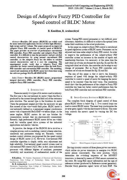
system. Tuning PID control parameters is very difficult, poor robustness, therefore, it's difficult to achieve the optimal state under field conditions in the actual production. In this paper an Adaptive-fuzzy PID control is introduced in speed regulation system of BLDC motor. Parameter can be adjusted real time under adaptive fuzzy PID control. In order to improve the performance of the Adaptive-fuzzy PID controller system an increase in the number of inputs and membership functions was necessary, at the same time the individual set of rules are formed for each Kp, Ki and Kd. By using individual set of rules, the controller can be adapt to any change of parameter. But in Fuzzy PID controller only common set of rule are formed for Kp, Ki and Kd. The aim of this paper is that it shows the dynamics response of speed with design the Adaptive-fuzzy PID controller to control a speed of motor for keeping the motor speed to be constant when the load varies. The simulation result show that the performance of the Adaptive Fuzzy PID controller has been has better control performance than the both Fuzzy PID controller and conventional PID controller.
机床整体控制专家系统及智能柔性驱动编程方案

Adaptive fuzzy logic controller for DC–DC convertersExpert Systems with ApplicationsThis paper introduces a complete design method to construct an adaptive fuzzy logic controller (AFLC) for DC–DC converter. In a conventional fuzzy logic controller (FLC), knowledge on the system supplied by an expert is required for developing membership functions (parameters) and control rules. The proposed AFLC, on the other hand, do not required expert for making parameters and control rules. Instead, parameters and rules are generated using a model data file, which contains summary of input–output pairs. The FLC use Mamdani type fuzzy logic controllers for the defuzzification strategy and inference operators. The proposed controller is designed and verified by digital computer simulation and then implemented for buck, boost and buck–boost converters by using an 8-bit microcontroller.Article Outline1. Introduction2. Basic design of adaptive fuzzy logic controller3. Adaptation algorithm for the fuzzy logic controller4. Computer simulation of the AFLC5. Implementation of the AFLC with microcontroller6. ConclusionCommissioning of textor CC, the new TEXTOR control system and first operating experiencesFusion Engineering and DesignThe old TEXTOR control systems have successfully been updated. The machine control has replaced by textor CC, a solution based on the software package WinCC produced by Siemens. WinCC, and therefore textor CC, can be easily integrated with the already available Siemens S5/S7 hardware components. This new system has the advantage that it is based on industrial soft- and hardware components.Therefore, the lifetime of the control system is extended and the maintenance effort is reduced. The installation and commissioning of the new control system was done in parallel to TEXTOR operation. During this time each function was tested and compared with the actual TEXTORdata. All functionality of the former control system was step-by-step replaced. Special attention was given to the visualization, data and error logging. Themachine control timing system has been replaced by an in house development in partnership with Siemens. It consists of transmitters and receivers based on PROFIBUS modules and is fully compatible with the pre-existing timing infrastructure. The old programmable function generator (PFG) has been replaced by compact RIO modules, controlled and programmed by Labview. This new PFG system allows to program up to 84 different time dependent signals. In this paper we intent to present a more detailed overview of our, on WinCC-based work, and a first status report on this new control system for TEXTOR.Article Outline1. Introduction2. Replacement of critical items2.1. Old S3 PLC-components2.2. Programmable function generator2.3. Timing2.3.1. Code generation2.3.2. Modules2.3.3. Software, Step7, WinCC3. textor CC4. Conclusion and outlookReferencesApplication of PLC to dynamic control system for liquid He cryogenic pumping facility on JT-60U NBI systemThe control system of the cryogenic facility in the JT-60 NBI system has been replaced by employing the PLC (Programmable Logic Controller) and SCADA (Supervisory Control And Data Acquisition) system. The original control system was constructed about 20 years ago by specifying the DCS (Distributed Control System) computer to deal with 400 feedback loops. Recently, troubles on this control system have increased due to its age-induced deterioration. To maintain the high reliability of the cryogenic facility, a new control system has been planned with the PLC andSCADA systems. Their attractive features include high market availability and cost-effectiveness, however, the use ofPLC for such a large facility with 400 feedback loops has not been established because of insufficient processing capability of the early PLC. Meanwhile, the recent progress in the PLC enables to use the FBD (function block diagram) programming language for 500 function blocks. By optimizing the function blocks and connecting them in the FBD language, the feedback loops have been successfully replaced from DCS to PLC without a software developer. Moreover, an oscillation of the liquid He level, which often occurs during the cooldown mode of the cryopumps, can be automatically stabilized by easily adding a new process program in the PLC. At present, the new control system has worked well.Article Outline1. Introduction2. Cryogenic facility for NBI system3. PLC based control system3.1. Design concept3.2. Construction of PLC based control system4. Operational results5. SummaryReferencesThe ECAL online software in the commissioning of the CMS detectorNuclear Instruments and Methods in Physics Research Section A: Accelerators, Spectrometers, Detectors and Associated EquipmentThe Electromagnetic Calorimeter (ECAL) of the Compact Muon Solenoid (CMS) detector at the CERN Large Hadron Collider (LHC) is a crystal homogeneous calorimeter made of about 76 000 lead tungstate crystals.The detector was installed in the CMS experimental cavern in 2007 and 2008 and was commissioned with cosmic rays and with LHC beams in 2008.The trigger and data acquisition system of the CMS ECAL comprises 35 000 Front End ASICs and 170 Off Detector VME Boards. The operation of the system, performed by the ECAL online software, requires the configuration of O(107) parameters and the realtime monitoring of O(105) registers. In this paper we discuss the design and architecture of the ECAL online software and its performances in cosmic ray runs and with the first LHC beams.Article Outline1. Introduction2. Architecture of the CMS ECAL DAQ system3. Role and performances of the ECAL online software in the commissioning of the CMS Electromagnetic Calorimeter4. ConclusionsAcknowledgementsCurrent sharing of paralleled DC–DC converters using GA-based PID controllersWe demonstrate a concept for pulse-width modulation (PWM) control of a parallel DC–DC buck converter, which eliminates the need for multiple physical connections of gating/PWM signals among the distributed converter modules. The proposed control concept may lead to easier distributed control implementation of parallel DC–DC converters and distributed power systems.For equipment with significant power requirement, the traditional single power supply may not be adequate. Many power supplies with parallel regulation control can be used to solve this problem. This paper proposes a Proportional-Integral-Derivative (PID) controller to control paralleled DC–DC buck converters and current sharing is achieved. A genetic algorithm (GA) is employed to derive optimal or near optimal PID controller gains. Both simulations and experimental results are provided to verify the theoretical analysis through an experimental prototype of paralleled DC–DC buck converters.Article Outline1. Introduction2. A GA-based PID controller design3. Stability analysis4. Experimental results4.1. Simulation results4.2. Experimental results5. ConclusionsAcknowledgementsIntegrated modeling and control of a PEM fuel cell power system with a PWM DC/DC converterPower Sources A fuel cell powered system is regarded as a high current and low voltage source. To boost the output voltage of a fuel cell, a DC/DC converter is employed. Since these two systems show different dynamics, they need to be coordinated to meet the demand of a load. This paper proposes models for the two systems with associated controls, which take into account a PEM fuel cell stack with air supply and thermal systems, and a PWM DC/DC converter. The integrated simulation facilitates optimization of the power control strategy, and analyses of interrelated effects between the electric load and the temperature of cell components. In addition, the results show that the proposed power control can coordinate the two sources with improved dynamics and efficiency at a given dynamic load.Article OutlineNomenclature1. Introduction2. Modeling of a fuel cell stack, air supply and thermal circuit2.1. PEM fuel cell stack2.1.1. Model improvement for the stack2.1.2. Parameters and simulation2.2. Air supply system2.3. Thermal system2.4. Controls for the air and coolant flow rate3. DC/DC converter4. Power control of the PEM fuel cell system with the DC/DC converter5. Integration and simulation6. ConclusionAcknowledgementsReferencesInterleaved soft-switched active-clamped L–L type current-fed half-bridge DC–DC converter for fuel cell applicationsInternational Journal of Hydrogen EnergyIn this paper, an interleaved soft-switched active-clamped L–L type current-fed half-bridge isolated dc–dc converter has been proposed. The L–L type active-clamped current-fed converter is able to maintain zero-voltage switching (ZVS) of all switches for the complete operating range of wide fuel cell stack voltage variation at full load down to light load conditions.Active-clamped circuit absorbs the turn-off voltage spike across the switches. Half-bridge topology maintains higher efficiency due to lower conduction losses. Soft-switching permits higher switching frequency operation, reducing the size, weight and cost of the magnetic components. Interleaving of the two isolated converters is done using parallel input series output approach and phase-shifted modulation is adopted. It reduces the input current ripple at the fuel cell input, which is required in a fuel cell system and also reduces the output voltage ripples. In addition, the size of the magnetic/passive components, current rating of the switches and voltage ratings of the rectifier diodes are reduced.Article Outline1. Introduction2. Operation and steady-state analysis3. Design, performance and simulation results4. Conclusion and summaryAppendix. Converter designReferencesDevelopment and commissioning results of the KSTAR discharge control systemThe Korea Superconducting Tokamak Advanced Research (KSTAR) control system has been developed as a network-based distributed control system composed of several sub-systems. There are many local control systems for various sub-systems, and the central control system includes discharge control, machine control, and safety interlocks which aim for integrated control of the entire system. We have chosen the Experimental Physics and Industrial Control System (EPICS) as the middleware of the KSTAR control system because EPICS provides a software framework to integrate heterogeneous systems. The discharge control system, which is implemented in a part of the supervisory control system, performs the discharge sequence execution. The plasma control system, which has been implemented with general atomics and modified for KSTAR, is involved in the discharge control. The plasma control system performs real-time plasma control algorithms and provides the results of the control algorithms to the magnet power supplies. We are using a reflective memory-based real-time network for communication between the plasma control system and the magnet power supplies, thus we developed a fully digital control for the magnet power supplies. We have implemented the discharge control system with state notation language (SNL) in EPICS and also developed interface software among the sub-systems. We will present the details of the development of the KSTAR discharge control system and commissioning results.Article Outline1. Introduction2. Discharge control system3. Implementations4. The results of commissioning and operationAcknowledgementsReferencesBeam-commissioning study of high-intensity accelerators using virtual accelerator modelIn order to control large-scale accelerators efficiently, a control system with a virtual accelerator model was constructed. The virtual accelerator (VA) is an on-line beam simulator provided with a beam monitor scheme. The VA is based upon the Experimental Physics and Industrial Control System (EPICS) and is configured under the EPICS input/output controller (IOC) in parallel with a real accelerator (RA). Thus, the machine operator can access the parameters of the RA through the channel access client and then feed them to the VA, and vice versa. Such a control scheme facilitates developments of the commissioning tools, feasibility study of the proposed accelerator parameters and examination of the measured accelerator data. This paper describes the beam commissioning results and activities by using the VA at the J-PARC 3-GeV rapid-cycling synchrotron (RCS).Article Outline1. Introduction2. EPICS control system and the VA2.1. EPICS control system2.2. Construction of VA system3. Beam commissioning by the VA3.1. Betatron tune3.2. Chromaticity3.3. Commissioning tool for injection line3.4. BPM polarity3.5. Optics correction4. Discussion5. SummaryAcknowledgementsThe commissioning and the first operational experiences of the CMS RPC detector control system at LHCThe CMS Resistive Plate Chambers (RPC) system consists of 912 double-gap chambers. The challenging constrains on the design and operation of this system imposed the development of a complex Detector Control System to assure the operational stability and reliability of a so large and complex detector and trigger system . The final layout and functionality of the CMS RPC DCS as well as the operational experience during the detector's commissioning and first phase of LHC operation are presented here.Article Outline1. Introduction2. The RCS low-level layers: description and performances2.1. The RPC power supply system2.2. RPC environmental and front-end electronics monitoring2.3. Gas and external systems monitoring3. The RCS software layers3.1. RCS supervisor architecture3.2. The RPC supervisor GUI4. Commissioning with cosmic rays and pp collisions5. ConclusionsSoftware architecture awareness in long-term software product evolution Systems and SoftwareSoftware architecture has been established in software engineering for almost 40 years. When developing and evolving software products, architecture is expected to be even more relevant compared to contract development. However, the research results seem not to have influenced the development practice around software products very much. The architecture often only exists implicitly in discussions that accompany the development. Nonetheless many of the software products have been used for over 10, or even 20 years. How do development teams manage to accommodate changing needs and at the same time maintain the quality of the product? In order to answer this question, grounded theory study based on 15 semi-structured interviews was conducted in order to find out about the wide spectrum of architecture practices in softwareproduct developing organisations. Our results indicate that a chief architect or central developer acts as a ‘walking architecture’ devising changes and discussing local designs while at the same time updating his own knowledge about problematic aspects that need to be addressed. Architecture documentation and representations might not be used, especially if they replace the feedback from on-going developments into the ‘architecturing’ practices. Referring to results fromComputer Supported Cooperative Work, we discuss how explicating the existing architecture needs to be complemented by social protocols to support the communication and knowledge sharing processes of the ‘walking architecture’.Article Outline1. Introduction2. Architecture, knowledge, and awareness2.1. Software architecture2.2. The role of the software architect2.3. Software product evolution and architecture2.4. Knowledge management2.5. Awareness in software engineering3. Research methodology3.1. Grounded theory3.2. Interviews3.3. Analytic process3.4. Confidence4. The companies and their architectural practice4.1. Interviewees and organisation profiles4.2. The presence of software architecture5. Analysis of interviews5.1. Architecture: who needs it and at what level?5.2. Documentation5.2.1. Code base as actual documentation5.2.2. The absence of a document5.3. Architecture knowledge acquisition: how newcomers learn the architecture5.3.1. Discussion with a chief architect5.3.2. Intermixed with programming5.3.3. Learning by doing5.4. The role of a chief architect5.4.1. Controlling and communicating architecture within a development team5.4.2. Updating the ‘walking architecture’5.4.3. Interfacing to outward5.5. Communication about changes5.5.1. Meeting5.5.2. Nightly builds and testing5.5.3. Concurrent versions system (CVS) and subversion repository5.5.4. Rich IDE5.5.5. Code review5.5.6. Wiki5.6. Evolution and changes5.7. The problems of the practitioners6. Discussion6.1. Architecture awareness is achieved through ‘walking architecture’ practices6.2. Good reasons for bad documentation6.3. How to promote architecture awareness7. ConclusionsAcknowledgementsReferencesTime delay control for fuel cells with bidirectional DC/DC converter and battery International Journal of Hydrogen Energy氢能源的电池组及其电子配件交流直流转化与驱动Transient behavior is a key property in the vehicular application of proton exchange membrane (PEM) fuel cells. A better control technology is constructed to increase the transient performance of PEM fuel cells. A steady-state isothermal analytical fuel cell model is constructed to analyze mass transfer and water transport in the membrane. To prevent the starvation of air in the PEM fuel cell, time delay control is used to regulate the optimum stoichiometric amount of oxygen, although dynamic fluctuations exist in the PEM fuel cell power. A bidirectional DC/DC converter connects the battery to the DC link to manage the power distribution between the fuel cell and the battery. Dynamic evolution control (DEC) allows for adequate pulse-width modulation (PWM) control of the bidirectional DC/DC converter with fast response. Matlab/Simulink/Simpower simulation is performed to validate the proposed methodology, increase the transient performance of the PEM fuel cell system and satisfy the requirement of energy management.Article Outline1. Introduction2. Fuel cell system model2.1. PEM fuel cell stack2.2. Airflow system2.3. Hydrogen flow system3. Flow control3.1. Feedfoward control3.2. TDC3.2.1. TDC compensator design3.2.2. TDC observer design4. Bidirectional DC–DC converter4.1. Bidirectional DC/DC converter topology4.2. Dynamic evolution control (DEC)5. Simulation results and analysis6. ConclusionAcknowledgementsA control-theoretic approach to the management of the software system test phaseA quantitative, adaptive process control technique is described using an industrially validated model of the software system test phase (STP) as the concrete target to be controlled. The technique combines the use of parameter correction and Model Predictive Control to overcome the problems induced by modeling errors, parameter estimation errors, and limits on the resources available for productivity improvement.We present an example of the technique applied to data from the execution of the STP of a commercial software development effort at a large software manufacturer. The example shows that the control technique successfully achieves the schedule and quality objectives despite uncertainty in the estimation of the model parameters.Article Outline1. Introduction1.1. Contributions1.2. Organization2. Related work2.1. Software testing2.2. Software process control2.3. Software process modeling2.4. Software cybernetics3. State model of the STP4. Problems of modeling4.1. Errors in the model4.2. Errors in the parameters5. Control objectives6. A model predictive control approach6.1. Retrain the model6.2. Linearize the model about the nominal trajectory6.3. Discretize the linearized model6.4. Solve an optimal control problem with the discretized model6.5. Implement the control suggestions7. Benefits of optimal control with constraints8. Choosing the cost matrices9. An illustrated example10. Applying the approach in practice11. Parameter identification11.1. The original calibration algorithm11.1.1. Estimating ζ and ξ11.1.2. Estimating x011.1.3. Re-estimating x011.1.4. Re-estimating ζ and ξ11.2. An alternative calibration algorithm11.2.1. Simulation11.2.2. Pre-fit data smoothing11.3. Assessment of the technique12. Conclusions and future workAcknowledgementsReferences5 kW级 DC/DC converter for hydrogen generation from photovoltaic sources五千瓦直流整流/稳压逆变器/变压器在氢能与太阳能发电站的运用This paper covers the design of a DC–DC power converter aimed for hydrogen production from photovoltaic sources. Power conditioning for such application is usually driven by different constraints: high step-down conversion ratio is required if the input voltage of such equipment has to be compatible with photovoltaic sources that are connected to grid-connected inverters; galvanic isolation; high efficiency and low mass. Taking into account those factors, this work proposes a push–pull DC/DC converter for power levels up to 5 kW. The operation and features of theconverter are presented and analyzed. Design guidelines are suggested and experimental validation is also given.Article OutlineNomenclature1. Introduction2. DC/DC converter: operation principle and features2.1. PV and electrolyser electrical models2.2. DC/DC converter design3. Application of a specific development3.1. Initial specifications: photovoltaic array and electrolyser3.2. Device selection3.3. Input and output filters: calculations and realisation3.4. Magnetic design: transformer and inductors3.5. Driving and PWM control circuits4. DC/DC converter simulations and experimental results5. ConclusionsControl and data flow structural testing criteria for aspect-oriented programsEssential communication practices for Extreme Programming in a global software development teamSoftware Technology全球软件开发团队开发超大型程序的交流沟通平台的实践评估We conducted an industrial case study of a distributed team in the USA and the Czech Republic that used Extreme Programming. Our goal was to understand how this globally-distributed team created a successful project in a new problem domain using a methodology that is dependent on informal, face-to-face communication. We collected quantitative and qualitative data and used grounded theory to identify four key factors for communication in globally-distributed XP teamsworking within a new problem domain. Our study suggests that, if these critical enabling factors are addressed, methodologies dependent on informalcommunication can be used on global software development projects.Article Outline1. Introduction2. Background and related work2.1. Global software development and requirements engineering practices2.2. Extreme programming2.3. Extreme programming case studies3. Research method4. Team and project description4.1. Team factors4.2. Process factors4.3. Project factors4.4. Project outcome5. Conjectures and recommendations5.1. A definitive customer role for requirements management activities5.2. Bridgehead5.3. Short, asynchronous communication loops5.4. Process visibility and control6. Case study limitations7. ConclusionAcknowledgementsAppendix A. AppendixA.1. Project-specific questionsComparison of control schemes for a fuel cell hybrid tramway integrating two dc/dc convertersInternational Journal of Hydrogen Energy氢发电电流转化附件选用与集成方案的对比分析This paper describes a comparative study of two control schemes for the energy management system of a hybrid tramway powered by a Polymer Electrolyte Membrane (PEM) Fuel Cell (FC) and an Ni-MH battery. The hybrid system was designed for a real surface tramway of 400 kW. It is composed of a PEM FC system with a unidirectional dc/dc boost converter (FC converter) and a rechargeable Ni-MH battery with a bidirectional dc/dc converter (battery converter), both of which are coupled to a traction dc bus. The PEM FC and Ni-MH battery models were designed from commercially available components.The function of the two control architectures was to effectively distribute the power of the electrical sources. One of these control architectures was a state machine control strategy, based on eight states. The other was a cascade control strategy which was used to validate the results obtained. The simulation results for the real driving cycle of the tramway reflected the optimal performance of the control systems compared in this study.Article OutlineNomenclature1. Introduction2. Description of the tramway3. Fuel cell–battery hybrid system3.1. Degree of FC–battery hybridization3.2. Fuel cell3.3. Battery3.4. FC converter3.5. Battery converter3.6. Tramway loads3.7. Braking chopper4. Control strategies for EMS of tramway4.1. State machine control strategy4.2. Cascade control strategy5. Simulation results6. ConclusionAcknowledgements(注:专业文档是经验性极强的领域,无法思考和涵盖全面,素材和资料部分来自网络,供参考。
三维电机智能无模型混合制导控制器设计(IJIEEB-V6-N5-5)

I.J. Information Engineering and Electronic Business, 2014, 5, 29-35Published Online October 2014 in MECS (/)DOI: 10.5815/ijieeb.2014.05.05Design Intelligent Model-free Hybrid Guidance Controller for Three Dimension Motor 1Abdol Majid Mirshekaran, 1Farzin Piltan, 1,2Nasri Sulaiman, 1Alireza Siahbazi, 1Ali Barzegar,1Mahmood Vosoogh1Research and Development Department, Institute of Advance Science and Technology-IRAN SSP, Shiraz/Iran,2 Department of Electrical and Electronic Engineering, Faculty of Engineering,Universiti Putra Malaysia, MalaysiaEmail: SSP.ROBOTIC@Abstract—The minimum rule base Proportional Integral Derivative (PID) Fuzzy hybrid guidance Controller for three dimensions spherical motor is presented in this research. A three dimensions spherical motor is well equipped with conventional control techniques and, in particular, various PID controllers which demonstrate a good performance and successfully solve different guidance problems. Guidance control in a three dimensions spherical motor is performed by the PID controllers producing the control signals which are applied to systems torque. The necessary reference inputs for a PID controller are usually supplied by the system’s sensors based on different data. The popularity of PID Fuzzy hybrid guidance Controller can be attributed to their robust performance in a wide range of operating conditions and partly to their functional simplicity. PID methodology has three inputs and if any input is described with seven linguistic values, and any rule has three conditions we will need 343 rules. It is too much work to write 343 rules. In this research the PID-like fuzzy controller can be constructed as a parallel structure of a PD-like fuzzy controller and a conventional PI controller to have the minimum rule base. Linear type PID controller is used to modify PID fuzzy logic theory to design hybrid guidance methodology. This research is used to reduce or eliminate the fuzzy and conventional PID controller problem based on minimum rule base fuzzy logic theory and modified it by PID method to control of spherical motor system and testing of the quality of process control in the simulation environment of MATLAB/SIMULINK Simulator.Index Terms—Fuzzy Hybrid guidance control, PID like fuzzy control, PD like fuzzy con trol, conventional PI control, three dimension spherical motor.I.I NTRODUCTIONMulti-degree-of-freedom (DOF) actuators are finding wide use in a number of Industries. Currently, a significant number of the existing robotic actuators that can realize multi-DOF motion are constructed using gear and linkages to connect several single-DOF motors in series and/or parallel. Not only do such actuators tend to be large in size and mass, but they also have a decreased positioning accuracy due to mechanical deformation, friction and backlash of the gears and linkages. A number of these systems also exhibit singularities in their workspaces, which makes it virtually impossible to obtain uniform, high-speed, and high-precision motion. For high precession trajectory planning and control, it is necessary to replace the actuator system made up of several single-DOF motors connected in series and/or parallel with a single multi-DOF actuator. The need for such systems has motivated years of research in the development of unusual, yet high performance actuators that have the potential to realize multi-DOF motion in a single joint. One such actuator is the spherical motor. Compared to conventional robotic manipulators that offer the same motion capabilities, the spherical motor possesses several advantages. Not only can the motor combine 3-DOF motion in a single joint, it has a large range of motion with no singularities in its workspace. The spherical motor is much simpler and more compact in design than most multiple single-axis robotic manipulators. The motor is also relatively easy to manufacture. The spherical motor have potential contributions to a wide range of applications such as coordinate measuring, object tracking, material handling, automated assembling, welding, and laser cutting. All these applications require high precision motion and fast dynamic response, which the spherical motor is capable of delivering. Previous research efforts on the spherical motor have demonstrated most of these features. These, however, come with a number of challenges. The spherical motor exhibits coupled, nonlinear and very complex dynamics. The design and implementation of feedback controllers for the motor are complicated by these dynamics. The controller design is further complicated by the orientation-varying torque generated by the spherical motor. Some of these challenges have been the focus of previous and ongoing research [1-5].Controller (control system) is a device to sense information from linear or nonlinear system (e.g., three degrees of freedom spherical motor) [6-10]. In feedback control system considering that there are many disturbances and also variable dynamic parameters something that is really necessary is keeping plant variables close to the desired value. Feedback controlsystem development is the most important thing in many different fields of safety engineering. The main targets in design control systems are safety stability, good disturbance rejection to reach the best safety, and small tracking error[11-15]. At present, in some applications spherical motors are used in unknown and unstructured environment, therefore strong mathematical tools used in new control methodologies to design nonlinear robust controller with an acceptable safety performance (e.g., minimum error, good trajectory, disturbance rejection). According to the control theory, systems’ controls are divided into two main groups: conventional control theory and soft computing control theory. Conventional control theories are work based on system dynamic model. This technique is highly sensitive to the knowledge of all parameters of nonlinear spherical motor’s dynamic equation. Conventional control theory is divided into two main groups: linear control theory and nonlinear control theory. Soft computing (intelligent) control theory is free of some challenges associated to conventional control theory. This technique is worked based on intelligent control theory. This theory is divided into the following groups: fuzzy logic theory, neural network theory, genetic algorithm and neuro-fuzzy theory. Although the fuzzy-logic control is not a new technique, its application in this current research is considered to be novel since it aimed for an automated dynamic-less response rather than for the traditional objective of uncertainties compensation[14-15]. The intelligent tracking control using the fuzzy-logic technique provides a cost-and-time efficient control implementation due to the automated dynamic-less input. This in turn would further inspire multi-uncertainties testing for spherical motor. In project we can use fuzzy logic theory when a plant can be considered as a black box with outputs available for measurement and a possibility of changing inputs. The plant is supposed to be observable and controllable. Some information about the plant operation or plant control is available, which can or cannot be of a quantitative nature, but it can be formulated as a set of rules (maybe after some processing). An acceptable fuzzy control solution is possible, which should satisfy design specifications. It must not be optimal in regard to some criteria as it is hard to prove that a fuzzy control system is optimal and even stable. However, a fuzzy controller is able to provide a stable and ‘good’ solution.This method is based on design minimum rule base Proportional Integral Derivative (PID) Fuzzy hybrid guidance Controller for three dimensions spherical motor is presented in this research. This research has two important objectives: reduce the number of PID fuzzy controller rule base, based on parallel methodology and modify the performance and guidance of fuzzy logic theory based on hybrid theory.This paper is organized as follows; section 2, is served as an introduction to the dynamic of three degrees of freedom spherical motor, design linear PID controller and fuzzy inference system. Part 3, introduces and describes the methodology algorithm. Section 4 presents the simulation results and discussion of this algorithm applied to three degrees of freedom spherical motor and the final section is described the conclusion.II.T HEORYDynamic and Kinematics Formulation of Spherical Motor: Dynamic modeling of spherical motors is used to describe the behavior of spherical motor such as linear or nonlinear dynamic behavior, design of model based controller such as pure sliding mode controller which design this controller is based on nonlinear dynamic equations, and for simulation. The dynamic modeling describes the relationship between motion, velocity, and accelerations to force/torque or current/voltage and also it can be used to describe the particular dynamic effects (e.g., inertia, coriolios, centrifugal, and the other parameters) to behavior of system[1-10]. Spherical motor has nonlinear and uncertain dynamic parameters 3 degrees of freedom (DOF) motor.The equation of a spherical motor governed by the following equation [1-10]:[̈][̇̇ ̇̇][̇̇][] (1)Where τ is actuation torque, H (q) is a symmetric and positive define inertia matrix, B(q) is the matrix of coriolios torques, C(q) is the matrix of centrifugal torques. This is a decoupled system with simple second order linear differential dynamics. In other words, the component ̈ influences, with a double integrator relationship, only the variable, independently of the motion of the other parts. Therefore, the angular acceleration is found as to be [1-11]:̈{{ }} (2)This technique is very attractive from a control point of view.Study of spherical motor is classified into two main groups: kinematics and dynamics. Calculate the relationship between rigid bodies and final part without any forces is called Kinematics. Study of this part is pivotal to design with an acceptable performance controller, and in real situations and practical applications. As expected the study of kinematics is divided into two main parts: forward and inverse kinematics. Forward kinematics has been used to find the position and orientation of task frame when angles of joints are known. Inverse kinematics has been used to find possible joints variable (angles) when all position and orientation of task frame be active [1].The main target in forward kinematics is calculating the following function:(3)Where is a nonlinear vector function,is the vector of task space variables which generally task frame has three task space variables, three orientation, is a vector of angles or displacement, and finally is the number of actuated joints. The Denavit-Hartenberg (D-H) convention is a method of drawing spherical motor free body diagrams. Denvit-Hartenberg (D-H) convention study is necessary to calculate forward kinematics in this motor.A systematic Forward Kinematics solution is the main target of this part. The first step to compute Forward Kinematics (F.K) is finding the standard D-H parameters. The following steps show the systematic derivation of the standard D-H parameters.1.Locate the spherical motorbel joints3.Determine joint rotation (4.Setup base coordinate frames.5.Setup joints coordinate frames.6.Determine, that, link twist, is the angle betweenand about an .7.Determine and , that , link length, is thedistance between and along . , offset, isthe distance between and along axis.8.Fill up the D-H parameters table. The second step tocompute Forward kinematics is finding the rotationmatrix (). The rotation matrix from{} to {}is given by the following equation;(4) Where is given by the following equation [1-11];[] (5) and is given by the following equation [1-11];[] (6) So () is given by [8](7)The final step to compute the forward kinematics is calculate the transformation by the following formulation [3][] (8)Fuzzy Logic Controller:Based on foundation of fuzzy logic methodology; fuzzy logic controller has played important rule to design nonlinear controller for nonlinear and uncertain systems [11-15]. However the application area for fuzzy control is really wide, the basic form for all command types of controllers consists of; Input fuzzification (binary-to-fuzzy [B/F] conversion) Fuzzy rule base (knowledge base), Inference engine and Output defuzzification (fuzzy-to-binary [F/B] conversion). Figure 1 shows fuzzy controller operation.Fig 1: Fuzzy Controller operationThe fuzzy inference engine offers a mechanism for transferring the rule base in fuzzy set which it is divided into two most important methods, namely, Mamdani method and Sugeno method. Mamdani method is one of the common fuzzy inference systems and he designed one of the first fuzzy controllers to control of system engine. Mamdani’s fuzzy inference system is divided into four major steps: fuzzification, rule evaluation, aggregation of the rule outputs and defuzzification. Michio Sugeno use a singleton as a membership function of the rule consequent part. The following definition shows the Mamdani and Sugeno fuzzy rule base(9) When and have crisp values fuzzification calculates the membership degrees for antecedent part. Rule evaluation focuses on fuzzy operation ( ) in the antecedent of the fuzzy rules. The aggregation is used to calculate the output fuzzy set and several methodologies can be used in fuzzy logic controller aggregation, namely, Max-Min aggregation, Sum-Min aggregation, Max-bounded product, Max-drastic product, Max-bounded sum, Max-algebraic sum and Min-max. Two most common methods that used in fuzzy logic controllers are Max-min aggregation and Sum-min aggregation. Max-min aggregation defined as below;⋃, * +- (10) The Sum-min aggregation defined asbelow⋃∑* + (11) where is the number of fuzzy rules activated by andand also ⋃ is a fuzzy interpretation of rule. Defuzzification is the last step in the fuzzy inference system which it is used to transform fuzzy set to crisp set. Consequently defuzzification’s input is the aggregate output and the defuzzification’s output is a crisp number. Centre of gravity method and Centre of area method are two most common defuzzification methods, which method used the following equation to calculate the defuzzification∑∑∑∑(12)and method used the following equation to calculate the defuzzification∑∑(13)Where and illustrates the crisp value of defuzzification output, is discrete element of an output of the fuzzy set, is the fuzzy set membership function, and is the number of fuzzy rules.Design PID Controller:Design of a linear methodology to control of continuum robot manipulator was very straight forward. Since there was an output from the torque model, this means that there would be two inputs into the PID controller. Similarly, the outputs of the controller result from the two control inputs of the torque signal. In a typical PID method, the controller corrects the error between the desired input value and the measured value. Since the actual position is the measured signal. Figure 2 shows linear PID methodology, applied to continuum robot manipulator [15].(14)̇∑ (15)Fig 2: Block diagram of linear PID methodThe model-free control strategy is based on the assumption that the joints of the manipulators are all independent and the system can be decoupled into a group of single-axis control systems [15]. Therefore, the kinematic control method always results in a group of individual controllers, each for an active joint of the manipulator. With the independent joint assumption, no a priori knowledge of robot manipulator dynamics is needed in the kinematic controller design, so the complex computation of its dynamics can be avoided and the controller design can be greatly simplified. This is suitable for real-time control applications when powerful processors, which can execute complex algorithms rapidly, are not accessible. However, since joints coupling is neglected, control performance degrades as operating speed increases and a manipulator controlled in this way is only appropriate for relatively slow motion [14]. The fast motion requirement results in even higher dynamic coupling between the various robot joints, which cannot be compensated for by a standard robot controller such as PID [13], and hence model-based control becomes the alternative.III.M ETHODOLOGYThis research focuses on the design two controllers; the first type of controller is PID like fuzzy logic controller based on 49 rule base and the second type of controller is linear PID controller to evaluate the PID like fuzzy controller. Based on previous discussion, fuzzy logic controller is work based on nonlinear dynamic rule bases. However this controller work in many applications but it cannot guarantee reliability and stability. To solve this challenge linear PID controller is used to improve the reliability and stability. Figure 3 Shows the PID like fuzzy hybrid guidance controller for spherical motor.Fig 3: Block diagram of Hybrid Guidance ControllerThe formulation of this controller is;∑ (16) Based on fuzzy logic methodology∑ (17) where is adjustable parameter (gain updating factor) and is defined by;∑∑(18)Where is membership function. According to the hybrid control theory;∑∑(19)One of the main artificial intelligence techniques is fuzzy logic theory. In this theory the behavior and dynamic of controller is defined by rule base. However defined and number of rule base play important role to design high quality controller but system has limitation to the number of rule base to implementation and the speed of response. Based on literature PID controller can reduce or eliminate the steady state error and design stable controller. But this type of controller has three types of inputs; proportional part, integral part and derivative part. To design PID like fuzzy controller and if any input is described with seven linguistic values, and any rule has three conditions we will need 7 × 7 × 7 = 343 rules. It is too much work to write 343 rules, the speed of system is too low and design embedded controller based on FPGA or CPLD is very difficult. Based on (9) the PID controller has three inputs and three coefficients. In PD like fuzzy controller error and change of error are the inputs and if any input is described with seven linguistic values, and any rule has two conditions we will need 7 × 7= 49 rules. In conventional PI controller error and integral of error are the inputs. The PID-like fuzzy controller can be constructed as a parallel structure of a PD-like fuzzy controller and a conventional PI- controller with the output approximated as:( ̇)∑ (20) In this type of design, we have 49 rule bases for PD like fuzzy controller. This PID like fuzzy controller applied to linear PID controller to remove the challenge in this research based on non-classical method and classical method. Figure 4 shows the block diagram of PID like fuzzy hybrid guidance controller.Fig 4: Block diagram of PID like Fuzzy Hybrid Guidance ControllerIV.R ESULTS A ND D ISCUSSIONPID like fuzzy hybrid guidance controller was tested to Step response trajectory. In this simulation is used to control position of spherical motor without and with external disturbance. The simulation was implemented in MATLAB/SIMULINK environment. These systems are tested by band limited white noise with a predefined 40% of relative to the input signal amplitude. This type of noise is used to external disturbance in continuous and hybrid systems and applied to nonlinear dynamic of these controllers.Tracking performances:stability and robust are two main important experiments under condition of certain and uncertain parameters. To test the stability, trajectory following is introduced. This part focuses on comparison between conventional PID control and PID like fuzzy hybrid guidance controller. Based on Fig 5, pure PID controller has a slight transient oscillation and overshoot, to solve this challenge hybrid guidance method is used also in proposed method the output gain updating factor must changed. In this design pure PID controller has about 2% overshoot but these two controller have the same rise time.Fig 5: PID controller and proposed method Disturbance rejection:this test is used to robust checking of controllers. Figure 6 shows the power disturbance elimination in proposed method and pure PID controller in presence of external disturbance and uncertainty parameters. The disturbance rejection is used to test and analyzed the robustness comparisons of these controllers for step trajectory. A band limited white noise with predefined of 40% the power of input signal value is applied to the step trajectory. According to the following graph, pure PID has moderate fluctuations in presence of external disturbance and uncertainty because this type of controller is linear and linear controller cannot guarantee the response of complex system (e.g., spherical motor) especially under condition of uncertainty and external disturbance.Fig 6: PID controller and proposed method in presence of externaldisturbanceTo eliminate above challenges, decrease the output scaling factor of the PID-part, increase the scaling factor for an integral input compared to other inputs, apply the centre of gravity defuzzification method, reduce the width of the membership function for the zero class of the error signal and Redistribute the membership functions, increasing their concentration around the zero point are offer.V.C ONCLUSIONThe central issues and challenges of nonlinear control and estimation problems are to satisfy the desired performance objectives in the presence of noises, disturbances, parameter perturbations, un-modeled dynamics, sensor failures, actuator failures and time delays. Evaluation algorithm proposed controller has shown growing popularity in both industry and academia. To improve the optimality and robustness, we have proposed PD like fuzzy controller parallel with PI controller based on 49 rule base for nonlinear systems with general performance criteria. Fuzzy controller provides us an effective tool to control nonlinear systems through the dynamic formulation of nonlinear system. Fuzzy logic controller is used to estimate highly nonlinear dynamic parameters. Mixed performance criteria have been used to design the controller and the relative weighting matrices of these criteria can be achieved by choosing different coefficient matrices. The simulation studies show that the proposed method provides a satisfactory alternative to the existing nonlinear control approaches.A CKNOWLEDGMENTThe authors would like to thank the anonymous reviewers for their careful reading of this paper and for their helpful comments. This work was supported by the SSP Institute of Advance Science and Technology Program of Iran under grant no. 2013-Persian Gulf-2A.R EFERENCES[1]Vachtsevanos, G. I., Davey, K. and Lee, K. M.,"Development of a Novel Intelligent Robotic Manipulator," IEEE Control System Magazine, 1987, pp.9-15.[2]Davey, K., Vachtsevanos, G. I., and Powers, R., "Ananalysis of Fields and Torques in Spherical Induction Motors," lEE Transactions on Magnetics, Vol. MAG-23, 1987, pp. 273-282.[3]Foggia, A., Oliver, E., Chappuis, F., "New Three Degreesof Freedom Electromagnetic Actuator," Conference Record -lAS Annual Meeting, Vol. 35, New York, 1988.[4]Lee, K. M., Vachtsevanos, G. and Kwan, C-K.,"Development of a Spherical Wrist Stepper Motor,"Proceedings of the 1988 IEEE lntemational Conference on Robotics and Automation, Philadelphia, PA. April 26-29.[5]Lee, K. M., Pei. I., "Kinematic Analysis of a ThreeDegree-of-Freedom Spherical Wrist Actuator," The Fifth International Conference on Advanced Robotics, Italy, 1991.[6]Wang, I., Jewel, G., Howe, D., "Modeling of a NovelSpherical Pennanent Magnet Actuator," Proceedings of IEEE International Conference on Robotics and Automation, Albuquerque, New Mexico, pp 1190-1195, 1997.[7]Wang, I., Jewel, G., Howe, D., "Analysis, Design andControl of a Novel Spherical Pennanent Magnet Actuator," lEE Proceedings on Electrical Power Applications., vol. 154, no. 1, 1998.[8]Chirikjian, G. S., and Stein, D., "Kinematic Design andCommutation of a Spherical Stepper Motor," IEEEIASME Transactions on Mechatronics, vol. 4, n 4, Piscataway, New Jersey, pp. 342-353, Dec. 1999.[9]Kahlen, K., and De Doncker, R. W., "CW'l'ent Regulatorsfor Multi-phase Pennanent Magnet Spherical Machines."Industry Applications Conference Record of the 2000 IEEE, vol. 3, 2000, pp. 2011-2016.[10]Lee, K. M., Pei, I., and Gilboa, U., "On the Developmentof a Spherical Wrist Actuator," Proceedings of the 16th NSF Conference on Manufacturing Systems Research, Tempe AZ, January 8-12, 1990.[11]Yang, C., Back, Y. S., "Design and Control of the 3-dcgn:es of freedom actuator by Controlling the Electromagnetic Force," IEEE Transactions on Magnetics, May, 1999, pp.3607-3609.[12]Mahdi Mirshekaran, Farzin Piltan,Zahra Esmaeili, TannazKhajeaian, Meysam Kazeminasab,"Design Sliding Mode Modified Fuzzy Linear Controller with Application to Flexible Robot Manipulator", IJMECS, vol.5, no.10, pp.53-63, 2013.DOI: 10.5815/ijmecs.2013.10.07.[13]Mojtaba Yaghoot, Farzin Piltan, Meysam Esmaeili,Mohammad Ali Tayebi, Mahsa Piltan,"Design Intelligent Robust Model-base Sliding Guidance Controller for Spherical Motor", IJMECS, vol.6, no.3, pp.61-72, 2014.DOI: 10.5815/ijmecs.2014.03.08.[14]Farzin Matin, Farzin Piltan, Hamid Cheraghi, NasimSobhani, Maryam Rahmani,"Design Intelligent PID like Fuzzy Sliding Mode Controller for Spherical Motor", IJIEEB, vol.6, no.2, pp.53-63, 2014. DOI:10.5815/ijieeb.2014.02.07.[15]Ali Barzegar, Farzin Piltan, Mahmood Vosoogh, AbdolMajid Mirshekaran, Alireza Siahbazi,"Design Serial Intelligent Modified Feedback Linearization like Controller with Application to Spherical Motor", IJITCS, vol.6, no.5, pp.72-83, 2014. DOI:10.5815/ijitcs.2014.05.10.Abdol Majid Mirshekaran is currentlyworking as a co researcher in Controland Robotic Lab at the institute ofadvance science and technology, IRANSSP research and development Center.He is a Master in field of ElectricalEngineering from Islamic AzadUniversity, IRAN. His current researchinterests are in the area of nonlinearcontrol, artificial control system and robotics, and spherical motor.Farzin Piltan was born on 1975, Shiraz, Iran. In 2004 he is jointed Institute of Advance Science and Technology, Research and Development Center, IRAN SSP. Now he is a dean of Intelligent Control and Robotics Lab. In addition to 7 textbooks, Farzin Piltan is the main author of more than 110 scientific papers in refereed journals. He is editorial reviewboard member for ‘international journal of control and automation (IJCA), Australia, ISSN: 2005-4297; ‘International Journal of Intelligent System and Applications (IJISA)’, Hong Kong, ISSN: 2074-9058; ‘IAES international journal of robotics and automation, Malaysia, ISSN: 2089-4856; ‘International Journal of Reconfigurable and Embedded Systems ’, Malaysia, ISSN: 2089-4864. His current research interests are nonlinear control, artificial control system and applied to FPGA, robotics and artificial nonlinear control and IC engine modeling and control.0Dr. Nasri Sulaiman. Received The B.Eng From University Of Putra Malaysia In 1994, M.Sc., From University Of Southampton, Uk In1999, And Phd Degrees From University Of Edinburgh, Uk In 2007, Respectively. He has more than 65 journal and conference papers. He Is Currently A Senior Lecturer In The Department OfElectrical Engineering At University Putra Malaysia Of The Program For Signal Processing, And Evolvable Harware (EHW) And Also Is Head Of Control And Automation Laboratory, Iranian Institute Of Advanced Science And Technology, Shiraz, Iran. He Is An Advisor In Spherical Motor Control.AliReza Siahbazi is currently working as a co researcher in Control and Robotic Lab at the institute of advance science and technology, IRAN SSP research and development Center. He is a Master in field of Computer Engineering from Shiraz University, Shiraz, IRAN. His current research interests are in the area ofnonlinear control, artificial control system and robotics, and spherical motor.Ali Barzegar is currently working as a co researcher in Control and Robotic Lab at the institute of advance science and technology, IRAN SSP research and development Center. His current research interests are in the area of nonlinear control, artificial control system and robotics, and spherical motor.Mahmood Vosoogh is currently working as a co researcher in Control and Robotic Lab at the institute of advance science and technology, IRAN SSP research and development Center. His current research interests are in the area of nonlinear control, artificial control system and robotics, andspherical motor.Howtocitethispaper: AbdolMajid Mirshekaran, Farzin Piltan, Nasri Sulaiman, Alireza Siahbazi, Ali Barzegar, Mahmood Vosoogh,"Design Intelligent Model-free Hybrid Guidance Controller for Three Dimension Motor", IJIEEB, vol.6, no.5, pp.29-35, 2014. DOI: 10.5815/ijieeb.2014.05.05。
LogicStudio效果器中文名称[整理]
![LogicStudio效果器中文名称[整理]](https://img.taocdn.com/s3/m/3d5f005de55c3b3567ec102de2bd960590c6d919.png)
Logic Studio 效果器中文名称compresso 压缩space designer 空间adaptive limiter 自适应限幅器pitch correction 螺距修正exciter 励磁机放大器模拟 Amplifier simulation Amp Designer 放大器的设计Bass Amp 低音安培Guitar Amp Pro 吉他放大器亲Pedalboard 效果器延迟 DelayDelay Designer 延迟设计器Echo 回声Sample Delay 采样延迟Stereo Delay 立体声延迟Tape Delay 磁带延失真 DistortionBitcrusher 低精度数码失真效果削波失真Distortion 失真效果Distortion II 失真2Overdrive 过载Phase Distortion 相位失真动态 DynamicAdaptive Limiter 自适应限幅器Compressor 压缩机DeEsser 嘶声消除器Ducker 帆布Enveloper 信封Expander 膨胀机Limiter 限制器Multipressor 多一些Noise Gate 噪声门Silver Compressor 银压缩机Silver Gate 银门Surround 环绕Compressor 压缩机均衡器 EqualizerChannel EQ 通道均衡DJ EQ DJ EQFat EQ 脂肪的EQLinear Phase EQ 线性相位均衡器Match EQ 匹配的EQ单频段均衡器单频段均衡器Silver EQ 银EQ滤波器 Wave filterAutoFilter 自动筛选EVOC 20 Filterbank 研祥20滤波器EVOC 20 研祥20 TrackOscillator 跟踪振荡器Fuzz-Wah 模糊华Spectral Gate 光谱选成像 ImagingBinaural PostProcessing 双耳后处理Direction Mixer 方向机Stereo Spread 立体传播指示 InstructionsBPM Counter BPM计数器Relevance indication 相关性指示Level Meter plugin 水平仪插件MultiMeter 多用表Surround MultiMeter 在万用表Tuner 调谐器调制 ModulationChorus Effect 合唱效果Ensemble Effect 集成效应Flanger Effect 镶边效应Microphaser 微移相器Modulation Delay 调制延迟Phaser Effect 相位的影响Ringshifter 环移相器Rotor Cabinet Effect 转子柜的影响Scanner Vibrato 扫描仪的颤音Effect 的影响Spreader 吊具Tremolo Effect 颤音效果音高 PitchPitch Correction 效果音调校正效果Pitch Shifter II 音调IIVocal Transformer 声乐变压器混响 ReverberationAVerb 动词EnVerb 在动词Gold Verb 金动词Platinum Verb 铂动词Silver Verb 银动词Space Designer 空间设计师Convolution Reverb 卷积混响特效 Special effectsDenoiser 更好的去噪效果Enhance Timing 提高定时Exciter 励磁机Groove shifter 槽移Speech Enhancer 语音增强SubBass 低音栓实用 UtilityDown Mixer 下混频器Gain Plug-in 增益插件I/O Utility I / O实用Multichannel Gain 多通道增益Test Oscillator 测试振荡器。
Fuzzy Logic and Systems

Fuzzy Logic and SystemsFuzzy logic is a fascinating concept that has gained popularity in various fields, including artificial intelligence, control systems, and decision-making processes. Unlike traditional binary logic, which deals with precise values of true or false, fuzzy logic allows for degrees of truth, making it more suitablefor handling uncertainty and imprecise information. This flexibility has made fuzzy logic a valuable tool in modeling complex systems and solving real-world problems. One of the key advantages of fuzzy logic is its ability to capture the vagueness and ambiguity present in human reasoning. By allowing for gradual transitions between true and false, fuzzy logic can better mimic human decision-making processes, which are often influenced by subjective factors and incomplete information. This human-like reasoning capability makes fuzzy logic particularly useful in applications where precise rules are difficult to define, such as in natural language processing or expert systems. In the field of control systems, fuzzy logic has been successfully applied to create more adaptive and robust controllers. Traditional control systems rely on precise mathematical models and algorithms, which may not always capture the complexity and variability of real-world systems. Fuzzy logic controllers, on the other hand, can adapt to changing conditions and handle uncertainties more effectively, making them suitable for applications such as temperature control, robotics, and automotive systems. Another area where fuzzy logic shines is in decision-making processes,particularly when dealing with complex and uncertain data. By allowing for the representation of vague concepts and fuzzy boundaries, fuzzy logic can help decision-makers make more informed and nuanced choices. This is especially valuable in situations where multiple conflicting criteria need to be considered, and traditional decision-making methods may fall short. Despite its many advantages, fuzzy logic is not without its challenges and limitations. One common criticism is the lack of a precise mathematical foundation, which can make it difficult to analyze and optimize fuzzy systems. Additionally, designing effective fuzzy logic systems often requires domain expertise and careful tuning of parameters, which can be time-consuming and resource-intensive. In conclusion, fuzzy logic offers a powerful framework for dealing with uncertainty andimprecision in various applications. Its ability to model human-like reasoning and handle complex systems make it a valuable tool for solving real-world problems. While there are challenges and limitations to consider, the potential benefits of fuzzy logic make it a compelling area of study and research for those looking to tackle complex and uncertain problems in a more human-like manner.。
- 1、下载文档前请自行甄别文档内容的完整性,平台不提供额外的编辑、内容补充、找答案等附加服务。
- 2、"仅部分预览"的文档,不可在线预览部分如存在完整性等问题,可反馈申请退款(可完整预览的文档不适用该条件!)。
- 3、如文档侵犯您的权益,请联系客服反馈,我们会尽快为您处理(人工客服工作时间:9:00-18:30)。
Abstract—This paper investigates the usage of Fuzzy Logic Controller (FLC) in controlling the liquid level in the second tank of Coupled-Tanks plant through variable manipulation of liquid pump in the first tank. System modeling involves developing a mathematical model by applying the fundamental physical laws of science and engineering. Simulation studies are then conducted based on the developed model using MatlabR2012a for Simulink. In this papers also study behavior system in terms of time response (e.g., steady state error, a certain rise-time, and overshoot) and compare FLC adverse PID controller.Index Terms—Fuzzy Logic Controller, Simulink , System Model.I.INTRODUCTIONThe industrial application of liquid level control is tremendous especially in refineries petroleum and chemical process industries[11]. Usually, level control exists in some of the control loops of a process control system. An evaporator system is one example in which a liquid level control system is a part of control loop. Evaporators are used in many chemical process industries for the purpose of separation of chemical products. Level control is also very important for mixing reactant process. The quality of the product of the mixture depends on the level of the reactants in the mixing tank. Mixing reactant process is a very common process in chemical process industries and food processing industries[5].Many other industrial applications are concerned with level control, may it be a single loop level control or sometimes multi-loop level control. In some cases, level controls that are available in the industries are for interacting tanks. Hence, level control is one of the control system variables which are very important in process industries[8].. Nowadays, chemical engineering systems are also at the heart of our economics[10]. The process industries such as refineries petrol, petro-chemical industries, paper making and water treatment industries require liquids to be pumped, stored in tanks, and then pumped to another tank[7]. In the design of control system, one often has a complicated mathematical model of a system that has been obtained from fundamental physics and chemistry . The above mentioned industries are the vital industries where liquid level and flow control are essential[9]. Many times the liquids will be processed by chemical or mixing treatment in the tanks, but always the level fluid in the tanks must be controlled, and the flow between tanks must be regulated. Level and flow control in tanks are the heart of all chemical engineering systems[11]. Manuscript received September, 2013.Dr.Abdelelah Kidher Mahmood, department of Electrical, University of Mosul / College Engineering, Mosul, Iraq,Hussam Hamad Taha, department of Electrical, University of Mosul/ College Engineering, Mosul, Iraq, The controller designed using fuzzy logic implements human reasoning that has been programmed into fuzzy logic language (membership functions, rules and the rules interpretation)It is interesting to note that the success of fuzzy logic control is largely due to the awareness to its many industrial applications. Industrial interests in fuzzy logic control as evidenced by the many publications on the subject in the control literature has created an awareness of its interesting importance by the academic community[8].II.SYSTEM MODELTwo interacting tanks in series with outlet flow rate being function of the square root of tank height[1] shown Fig.1.A.Modeling equationsBy applying the laws of physics to get a mathematical model of the system to become the dynamic equation of the system, as in equations (1)&(2).211111-hhARAFdtdh (1)2221212ARhhARdtdh (2)Where :F=steady-state liquid flow rate ,c m3/sec.1F= out flow rate from first tank, cm3/sec.2F= out flow rate from second tank, cm3/sec.1R and2R= coefficients, cm2.5/sec.(1h= level first tank ,cm .2h= level second tank ,cm).1A=the cross sectional area for first tank, cm2.2A=the cross sectional area for second tank ,cm2.III.SIMULINK BLOCK DIAGRAM DESCRIPTION Simulink model for liquid level control and Fuzzy Logic Controller and by using program MatlabR2012a. Based on the dynamic equations (1) and (2) a simulink block diagramDesign Fuzzy Logic Controller for LiquidLevel ControlAbdelelah Kidher Mahmood, Hussam Hamad TahaFig.2 showing the nonlinear model of the plant can be formed successively .Fig.3 shows the subsystem embedding the Simulink block diagram of the nonlinear model of the plant. For pumping liquid is pumping capacity (F= 5 cm3\sec).Fig2. Simulink for Control System with FLCIV.DESIGNING OF FUZZY LOGIC CONTROLLER A.Fuzzy Logic Controller ReviewFuzzy logic is a part of artificial intelligence or machine learning which interprets a human’s actions. Fuzzy techniques have been successfully used in control in several fields. Fuzzy logic is a form of logic whose underlying modes of reasoning are approximate instead of exact. The general idea about fuzzy logic is that it takes the inputs from the sensors which is a crisp value and transforms it into membership values ranging from 0 to 1[3]. Unlike crisp logic ,it emulates the ability to reason and use approximate data to find solutions. Fuzzy logic controllers (FLCs) are knowledge-based controllers consisting of linguistic “IF-TH EN” rules that can be constructed using the knowledge of experts in the given field of interest[6].Despite the variety of possible fuzzy controller structures, the Fig.4 is shown all common types of controllers consist of:• Input fuzzification (binary-to-fuzzy [B/F] conversion)• Fuzzy rule base• Inference engine• Output defuzzification (fuzzy-to-binary [F/B] conversion) [4].Crisp input Fuzzification Rule Base DefuzzificationInferenceCrispoutputFig4. Fuzzy SystemB.I nputs and Output for SystemWe have defined two inputs and one output for the fuzzy logiccontroller may be shown as Fig.5. One is error that range ofthe liquid in the second tank denoted as “error” thatrepresented 2hherrorref if refhthe set point forlevel that control on it, and the other one is ratio of change ofliquid in the second tank denoted as “rate” . The highest valueof the liquid level is 13, which represents the height of eachtank of two tanks that the error rate ranging from -13 to 13, sothe error range of input “error” is from -13 to 13 either input“rate” range from -0.2to 0.2 ,the range output -100 to 100 thatrepresents “pump” . The input “error”is divided into threemembership functions are "low" , "okay" and "high", eitherinput “rate” isdividedinto threemembership functions"negative" , "none" and "positive", the output “pump” isdivided into five membership functions "close fast" , "closelow" and "no change" , "open low" and "open fast" and areused triangular membership functions in the inputs and outputFig.6 illustrate this. Both these inputs are applied to the ruleeditor. According to the rules written inthe rule editor the controller takes the action and governs the running of the pump which is the output of the controller and is denoted by “pump”[2].Fig5. FIS EditorFig 6. The Memberships Inputs and OutputsC.T he Fuzzy RuleConstructing rules using the graphical Rule Editor interface is very clearly. Based on the descriptions of the input and output variables defined with the FIS Editor, the Rule Editor allows you to construct the rule statements automatically, by clicking on and selecting one item in each input variable box,one item in each output box, and one connection item[8].Fig.7 illustrate rule bases that used in the fuzzy logic controller.Fig 7. Rule Bases for Fuzzy Logic ControllerV. PID CONTROLLERWe are using PID controller to compare with fuzzy logic controller ,for finding constants controller use tool "PID" in simulation of MatlabR2012a program, which depends on thefrequency response at the calculate of constants controllerFig 8. Method Calculate Constants Controller (PID) Fig.8 illustrate the method calculate constants controller.Fig 9. Simulink for Control System with PID ControllerFig.9 simulink for control system with PID Controller. VI. SIMULATION RESULTSResponse of second tank level using fuzzy logic controller Fig.10 provide good performance in terms of oscillations and overshoot in the absence of a prediction mechanism and Fig.11 illustrate response of second tank if acquire any leakage or disturbance in tank and that demonstrates how to return the controller to control the liquid level and the same performance without get any oscillations or overshoot .Otherwise, Response of liquid level controller using PID controller Fig.12 it is seen that PID controllers provide performance in terms of oscillations and overshoot in the presence of a prediction mechanism and Fig.13 illustrateresponse of second tank if acquire any leakage or disturbance in tank and that demonstrates how to return the controller to control the liquid level and the same performance in transients with presence oscillations or overshoot that lead to instability system.Fig 10. Response of Second Tank using FLCFig 11. Response of Second Tank with Leakage or Disturbance in Liquid Level for FLCh2 in cmFig 12. Response of Second Tank using PIDh2 in cmFig 13. Response of Second Tank with Leakage or Disturbance in Liquid Level for PIDh2 in cmVII. DISCUSSIONThe FLC is applied to the plant ,the results have been obtainedfrom simulation are plotted against with that of conventional controller PID controller for comparison purposes. The simulation results are obtained using a 5 rule FLC. Rules shown in Rule Editor provide inference mechanism strategy and producing the control signal as output. For comparison purposes ,simulation plots include a conventional PID controller, and the fuzzy algorithm. FLC provide good and satisfactory time domain response performance in terms of oscillations and overshoot are quite absence due to prediction mechanism. The FLC algorithm adapts quickly to longer time delays and provides a stable response while the PID controllers may drive the system unstable due to mismatch error generated by the inaccurate time delay parameter used in the plant model. From the simulations, in the presence of unknown or possibly varying time delay, theproposed FLC shows a significant improvement in maintaining performance and preserving stability over standard PID method .To strictly limit the overshoot, a Fuzzy Control can achieve great control effect. In this paper, we take the liquid level tank , and use MatlabR2012a to design a Fuzzy Control. Then we analyze the control effect and compare it with the effect of PID controller. As a result of comparing, Fuzzy Control is superior to PID control. Especially, it can give more attention to various parameters, such as the time of response, the error of steadying and overshoot. Comparison of the control results from these two systems indicated that the fuzzy logic controller significantly reduced overshoot and steady state error. Comparison results of PID and FLC are shown Table I below. The overall performance may be summarized as:VIII.CONCLUSIONUnlike the conventional PID controller the Fuzzy Logic Controller has benefits on the system response ,a unique FLC using a small number of rules and straightforward implementation has been proposed to solve a class of level control problems with unknown dynamics or variable time delays commonly found in industry. Additionally, the FLC can be easily programmed into many currently available industrial process controllers. The FLC on a level control problem with promising results can be applied to an entirely different industrial level controlling apparatus .As a future work one can develop design a FLC for a couple tanks system as adaptive Fuzzy Logic Controller like PID algorithm, which gives high performance for systems and high intelligence.REFERENCES[1]Katsuhiko Ogata,“Modern Control Engineering“, Fifth Edition, 2010,905pp.[2] User's Guide of Matlab for Fuzzy Logic Toolbox.2012.B.[3]Elmer P. Dadios," Fuzzy Logic –Controls, Concepts, Theories andApplications", First Edition ,Janeza Trdine 9, 51000 Rijeka, Croatia, 2012,428pp.[4]Zdenko Kovaˇci´and Stjepan Bogdan"Fuzzy Controller Design Theoryand Applications", CRC Press Taylor & Francis Group, 2006,392pp.[5]Carlos A. Smith, Ph.D., P.E. &Armando B. Corripio, Ph.D.,P.E."Principles and Practice of Automatic Process Control" Second Edition, 1997,783pp.[6]S. N. Sivanandam, S. Sumathi and S. N. Deepa"Introduction to FuzzyLogic using MATLAB",Springer-Verlag Berlin Heidelberg 2007,441pp.[7]P. Berk*, D. Stajnko, P. Vindis, B. Mursec, M. Lakota "Synthesiswater level control by fuzzy logic" International OCSCO World Press, Volume 45,Issue 2,April 2011,pp.204-210.[8]Dharamniwas , Aziz Ahmad , Varun Redhu and Umesh Gupta,"Liquid Level Control by using Fuzzy Logic Controller", International Journal of Advances in Engineering & Technology, July 2012. Vol. 4, Issue 1, pp. 537-549.[9]G.Sakthivel & T.S.Anandhi & S.P.Natarajan," Design of Fuzzy LogicController for a Spherical tank system and Its Real Time Implementation",G.Sakthivel,T.S.Anandhi,S.P.Natarajan/International Journal of Engineering Research and Applications (IJERA), Vol. 1, Issue 3, pp.934-940. [10] Elke Laubwald, " Coupled Tanks Systems 1 " Visiting Scientist,control systems [11]Abdul Rasyid Bin Mohammd Ali,"Optimization of ControllerParameters for A Couple Tanks System using Metamodelling Technique",Thesis submitted for Bachelor of Electrical Engineering (Mechatronics), University Technology Malaysia, 2009,147 pp.Abdelelah Kidher Mahmood: was boringonJuly-1955,Kirkuk-IRAQ, he receivedPh.D. inControlEngineering from SaintPeters burg. University Russia in 1992.M.Sc., Pg. Dip ,B.Sc. in Electronic andCommunication, Department of ElectricalEngineering, University of Mosul, IRAQ,1981, 1979, and 1978, respectively.Assistance Professor from 2008, Lecturer 1993-2008, Assistance Lecturer 1984-1993. Member of IEEE-2009. His research interest include Control Engineering, Fuzzy Logic, Intelligent Techniques, Real Time Digital Control. Fractional order controller.Hussam Hamad Taha: was boring on February-1985, Kirkuk –IRAQ ,he received B.Sc. inControl and System Engineering from TechnologyUniversity IRAQ in 2007, M.Sc. student inControl, Department of Electrical Engineering,University of Mosul, IRAQ . His research interestinclude Control Engineering, Fuzzy Logic,Intelligent Techniques, Real Time Digital Control. Process Control.。