FP-CH302
8002冠号
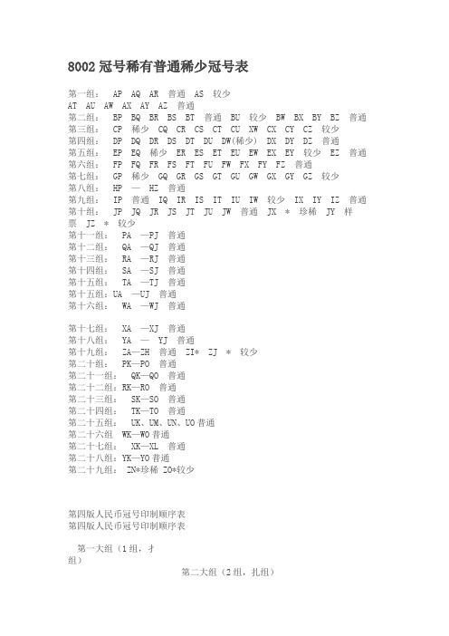
8002冠号稀有普通稀少冠号表第一组:AP AQ AR 普通AS 较少AT AU AW AX AY AZ 普通第二组:BP BQ BR BS BT 普通BU 较少BW BX BY BZ 普通第三组:CP 稀少CQ CR CS CT CU XW CX CY CZ 较少第四组:DP DQ DR DS DT DU DW(稀少) DX DY DZ 普通第五组:EP EQ 稀少ER ES ET EU EW EX EY 较少EZ 普通第六组:FP FQ FR FS FT FU FW FX FY FZ 普通第七组:GP 稀少GQ GR GS GT GU GW GX GY GZ 较少第八组:HP —HZ 普通第九组:IP 普通IQ IR IS IT IU IW 较少IX IY IZ 普通第十组:JP JQ JR JS JT JU JW 普通JX * 珍稀JY 样票JZ * 较少第十一组:PA —PJ 普通第十二组:QA —QJ 普通第十三组:RA —RJ 普通第十四组:SA —SJ 普通第十五组:TA —TJ 普通第十五组:UA —UJ 普通第十六组:WA —WJ 普通第十七组:XA —XJ 普通第十八组:YA —YJ 普通第十九组:ZA—ZH 普通ZI* ZJ * 较少第二十组:PK—PO 普通第二十一组:QK—QO 普通第二十二组:RK—RO 普通第二十三组:SK—SO 普通第二十四组:TK—TO 普通第二十五组:UK、UM、UN、UO普通第二十六组WK—WO普通第二十七组:XK—XL 普通第二十八组:YK—YO普通第二十九组: ZN*珍稀 ZO*较少第四版人民币冠号印制顺序表第四版人民币冠号印制顺序表第一大组(1组,扌组)第二大组(2组,扎组)C组 CP CQ CR CS CT CU CW CX CY CZ P组 PA PB PC PD PE PF PG PH PI PJE组 EP EQ ER ES ET EU EW EX EY EZ R组 RA RB RC RD RE RF RG RH RI RJG组 GP GQ GR GS GT GU GW GX GY GZ T组 TA TB TC TD TE TF TG TH TI TJI组 IP IQ IR IS IT IU IW IX IY IZW组 WA WB WC WD WE WF WG WH WI WJA组 AP AQ AR AS AT AU AW AX AY AZ Y组 YA YB YC YD YE YF YG YH YI YJB组 BP BQ BR BS BT BU BW BX BY BZ Q组 QA QB QC QD QE QF QG QH QI QJD组 DP DQ DR DS DT DU DW DX DY DZ S组 SA SB SC SD SE SF SG SH SI SJF组 FP FQ FR FS FT FU FW FX FY FZ U组 UA UB UC UD UE UF UG UH UI UJH组 HP HQ HR HS HT HU HW HX HY HZ X组 XA XB XC XD XE XF XG XH XI XJJ组 JP JQ JR JS JT JU JW JX JY JZ Z组 ZA ZB ZC ZD ZE ZF ZG ZH ZI ZJ第三、四大组(3组,打组)第五、六大组(4组,扛组)P、R组 PK PL PM PN PO RK RL RM RN RO K组 KP KQ KR KS KT KU KW KX KY KZT、W组 TK TL TM TN TO WK WL WM WN WO M组 MP MQ MR MS MT MU MW MX MY MZY、Q组 YK YL YM YN YO QK QL QM QN QO O组 OP OQ OR OS OT OU OW OX OY OZS、U组 SK SL SM SN SO UK UL UM UN UO L组 LP LQ LR LS LT LU LW LX LY LZX、Z组 XK XL XM XN XO ZK ZL ZM ZN ZO N 组 NP NQ NR NS NT NU NW NX NY NZA、C组 AK AL AM AN AO CK CL CM CN CO K组 KA KB KC KD KE KF KG KH KI KJE、G组 EK EL EM EN EO GK GL GM GN GO M组 MA MB MC MD ME MF MG MH MI MJI、B组 IK IL IM IN IO BK BL BM BNBO O组 OA OB OC OD OE OF OG OH OI OJD、F组 DK DL DM DN DO FK FL FM FN FO L组 LA LB LC LD LE LF LG LH LI LJH、J组 HK HL HM HN HO JK JL JM JN JO N组 NA NB NC ND NE NF NG NH NI NJ第七大组(5组,抖组)第八大组(6组,拉组)A组 AA AB AC AD AE AF AG AH AI AJ P组 PP PQ PR PS PT PU PW PX PY PZC组 CA CB CC CD CE CF CG CH CI CJ R组 RP RQ RR RS RT RU RW RX RY RZE组 EA EB EC ED EE EF EG EH EI EJ T组 TP TQ TR TS TT TU TW TX TY TZG组 GA GB GC GD GE GF GG GH GI GJ W组 WP WQ WR WS WT WU WW WX WY WZI组 IA IB IC ID IE I FIG IH II IJ Y组 YP YQ YR YS YT YU YW YX YY YZB组 BA BB BC BD BE BF BG BH BI BJ Q组 QP QQ QR QS QT QU QW QX QY QZD组 DA DB DC DD DE DF DG DH DI DJ S组 SP SQ SR SS ST SU SW SX SY SZF组 FA FB FC FD FE FF FG FH FI FJ U组 UP UQ UR US UT UU UW UX UY UZH组 HA HB HC HD HE HF HG HH HI HJ X组 XP XQ XR XS XT XU XW XX XY XZJ组 JA JB JC JD JE JF JG JH JI JJ Z组 ZP ZQ ZR ZS ZT ZU ZW ZX ZY ZZ说明:各个印钞厂都是按照这个表,从左到右、从上到下的顺序印制。
Panasonic 可编程控制器FP系列 编程手册
FP系列编程手册(补充版)
[ 适用机型 ] FP-X FPΣ FP2/FP2SH
※请同时参考FP系列编程手册(No.ARCT1F313C-1)
FP系列可编程控制器编程手册 ARCT1F433C ’07年2月
http://www.mew.co.jp/ac/c/
目录
基本指令············································································································Байду номын сангаас·························· 1-1
高级指令······································································································································· -2-1
F0(MV) F0(MV) F1(DMV) F4(GETS) F145(SEND)· F145(SEND)· F146(RECV) F146(RECV) F159(MTRN)· F159(MTRN)· F161(MRCV) F166(HC1S) F167(HC1R) F171(SPDH) F171(SPDH) F172(PLSH) F173(PWMH) F174(SP0H) F175(SPSH) F182(FILTR) F230(TMSEC) F231(SECTM) F250(BTOA) F251(ATOB) F252(ACHK) F284(RAMP) F354(FSCAL) F356(EZPID) 高速计数器控制 ··············································································································2-2 脉冲输出控制 ·················································································································2-5 高速计数器/脉冲输出经过值的写入和读出 ·····································································2-8 读取指定槽的起始字 No. ································································································2-10 数据的发送(MEWTOCOL 主站模式)··············································································2-12 数据发送(MODBUS 主站模式) ··················································································2-14 数据的接收(MEWTOCOL 主站模式) ·········································································2-18 数据的接收(MODBUS 主站模式) ···············································································2-20 串行数据通信(FP-XFPSigma) ···················································································2-24 串行数据发送(FP2 复合通信单元 COM 端口) ··························································2-28 串行数据接收(FP2 复合通信单元 COM 端口) ··························································2-30 目标值一致 ON(带通道指定) ·····················································································2-32 目标值一致 OFF(带通道指定) ···················································································2-34 脉冲输出(带通道指定)(梯形控制) ·········································································2-36 脉冲输出(带通道指定) (原点返回) ··················································································2-39 脉冲输出(带通道指定)(JOG 控制) ············································································· 2-42 PWM 输出(带通道指定) ·····························································································2-44 脉冲输出(带通道指定)(可选择数据表控制)································································2-46 脉冲输出(直线插补)········································································································2-48 时常数处理 ·····················································································································2-50 时间数据→ 秒转换 ········································································································2-52 秒→ 时间数据转换 ········································································································2-54 二进制→ASCII 转换 ·······································································································2-56 ASCII 码→二进制转换 ··································································································· 2-60 ASCII 数据检查 ·············································································································· 2-62 16 位数据的倾斜输出 ·····································································································2-63 实数数据的定标 ··············································································································2-66 简单的 PID ·····················································································································2-68
贴片三极管标识代号
汶川地 震,我们 看到什么
what is love 贴片三极 管代码1
work 2008-0528 21:43:04 阅读2529 评论11 字号:大 中小 JX SOT23 BAV170 B dual cc Si diode low Ir JY SOT23 BAV199 dioda-2x JY SOT23 BAV199 D dual series Si diode lowIr JZ SOT23 BAW 156 JZ SOT23 BAW156 A dual ca Si diode low Ir K SCD80 BBY5202W I UHF varicap 1.751.25pF
K15 DTA124G N pnp sw 50V 50mA w. b-e res K1p SOT23 BCW71 N BC107A K1t SOT23 BCW71 N BC107A K1X SOT23 KSC3265 NPN K2 SOT23 BCW72 NPN K2 SOT23 BCW72 N BC107B ZXT300 K2 SOT23 HSMP3832 D dual HP3830 pin diode K24 DTC114G N npn sw 50V 100mA w. b-eres
L5 SOT23 MMBC1623 L5 NPN L51 SOT143 BAS56 dioda-2x L51 SOT143 BAS56 S dual 60V 200mA diodes L52 SOT23 BAS678 dioda L6 BAR17 C pin diode L6 BSS69R N pnp 40V 0.1A 200MHz sw L6 MMBC1623 L6 N MPS3904 hfe 200400 L6 SOT23 BAR17 dioda L6 SOT23 BSS69R PNP
常用塑胶原料厂牌及牌号

常用塑胶原料厂牌及牌号PP(高聚物聚丙烯)廠牌牌號泰国HP480S、332K、3342M、3342R、348S、1100NK、1102、1126NK、200F、348N茂名T30S、T36F、V30G台塑3015、1005、1040、1080、1120、1124、2080、3040、3040C、FPD943、K1011 K1023 北京B303、EPC30R、HHP1、HHP3、HHP4印度SS35N、H030SG、H100EY、H110MA台湾3010、K1020、K1011、K1023、K1035、K4015、K4515、K4535、K8010、K8025、K8802、1005、T8002、4210、4410、7533、6331、7633 ST868M日本住友W531、W531A韩国现代H1500、H5300、DJ560S、DJ570S、H1501、H4540、M1250、M1600、R1610、DJ570S、台湾永嘉1120、3204、5020、3015、3080、5090T燕山石化1300、B4808、K1001、K1003、K1005、K1008、K4818、K4912、K7726、K7760、K8303、K9020、K9035、T1701、T1702扬子石化F401、F501、J301G、J340、K8003、K9015、K9927、S1004、S2309、S700、3008、307G、706上海赛科K4912、M800E、3317、510M、C1007、K4912、K7926、K7930、K8003、S1003、S2040宁波1120、3015、5090T台湾福聚366-3、366-4、366-5、6331、6524、73F4-3、7533、7633、7633-3、7633U、PD943、ST751、ST031、ST868M、ST869M、PJ3001、PJ3003、PJ3004台湾南亚3219M3、3317、3307、3117、3310韩国晓星J440、J440X、J640、J740X、J801R、HJ800R、HJ801R、J440W、R300X、R301、R530A、J340、B100N、J700、J742S、R401、R601、R701新加坡7033N、9999SS、AW564、AZ864、AY564、W531L、W531P、Y101H、Z433、1304E1、AP03B韩国锦湖H150U美国0544、GF30-04、H17UC00、TS01广州金发PP-20、R008、G220、R30-701、TC15G、FR-NC03香港NB2620G、NB2630G美国液氮MFL-36S、4036HS、MS-1003南非100P、HKR102埃克森7032E3、7033E3、AP03B、AP3AW、AP7885巴赛尔EP300H、HP550J、KY6110巴西H103、H503中石油A180TM、A002TM、A200T、AF005、DY-GK2590S、W0723F、W0825RT俄罗斯21030法国3365沙特500P、520L、570P、575P、578P、670K、910MNK40上海石化F800E、M1600E、M180R、M250E、M2600R、M450E、M500、M700R、M800E、T300、Y2600、Y3700CPP填充级(滑石粉填充10%-30%)、高刚性、高耐热。
8001已见发行514种冠号
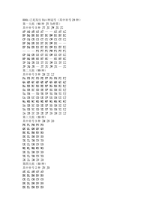
8001已见发行514种冠号(其中补号29种)第一大组(90种 JY为样票)其中补号5种 JT JU JW JX JZAP AQ AR AS AT —— AX AY AZBP BQ BR BS BT BU BW BX BY BZCP CQ CR CS CT CU CW CX CY CZDP DQ DR DS DT DU DW DX ——EP EQ ER ES ET EU EW EX EY EZ——— FS FT FU FW FX FY FZGP GQ GR GS GT GU GW GX GY GZHP HQ HR HS HT HU — HX HY HZIP IQ IR IS IT IU IW IX IY IZJP JQ JR — JT JU JW JX — JZ第二大组(99种)其中补号3种 ZH ZI ZJPA PB PC PD PE PF PG PH PI PJQA QB QC QD QE QF QG QH QI QJRA RB RC RD RE RF RG RH RI RJSA SB SC SD SE SF SG SH SI SJTA TB — TD TE TF TG TH TI TJUA UB UC UD UE UF UG UH UI UJWA WB WC WD WE WF WG WH WI WJXA XB XC XD XE XF XG XH XI XJYA YB YC YD YE YF YG YH YI YJZA ZB ZC ZD ZE ZF ZG ZH ZI ZJ第三大组(50种)其中补号3种 ZM ZN ZOPK PL PM PN POQK QL QM QN QORK RL RM RN ROSK SL SM SN SOTK TL TM TN TOUK UL UM UN UOWK WL WM WN WOXK XL XM XN XOYK YL YM YN YOZK ZL ZM ZN ZO第四大组(50种)其中补号2种 JN JOAK AL AM AN AOBK BL BM BN BOCK CL CM CN CODK DL DM DN DOEK EL EM EN EOFK FL FM FN FOGK GL GM GN GOHK HL HM HN HOIK IL IM IN IOJK JL JM JN JO第五大组(50种)其中补号2种 NY NZKP KQ KR KS KT KU KW KX KY KZLP LQ LR LS LT LU LW LX LY LZMP MQ MR MS MT MU MW MX MY MZNP NQ NR NS NT NU NW NX NY NZOP OQ OR OS OT OU OW OX OY OZ第六大组(95种)其中补号7种 JA ** JC JG JH JI JJAA AB AC AD AE AF AG AH AI AJBA BB BC BD BE BF BG BH BI —CA CB CC CD CE CF CG CH CI CJDA — DC DD DE DF DG DH DI DJEA EB EC ED —— EG EH EI EJFA FB FC FD FE FF FG FH FI FJGA GB GC GD GE GF GG GH GI GJHA HB HC HD HE HF HG HH HI HJIA IB IC ID IE IF IG IH II IJJA ** JC — JE JF JG JH JI JJ第七大组(12种)其中补号1种 NJKA KB KC KD KE KF KG KH KI KJ—— MC ———————————————— NJ第八大组(68种)其中补号6种 ZT ZU ZW ZX ZY ZZPP PQ PR PS PT PU PW PX PY PZQP QQ QR ———— QX QY QZRP RQ RR RS RT RU RW RX RY RZSP —— SS — SU SW SX SY —TP TQ TR TS TT TU TW TX TY TZUS UUWP WQ — WS WT WU WW WX WY ——— XR XZ YP — YR YS ——— YX — YZZP ZQ ZR — ZT ZU ZW ZX ZY ZZ注:8001冠号仍在陆续发行中。
abb自控系统硬件表
AI 8ch,0/4-20 mA,安全栅
AI893
AI 8ch,TC(B,C,E,J,K,N,R,S,T),安全栅
AI895
AI 8ch,0/4-20 mA,安全栅,HART
AI880A
AI 8ch,0/4-20mA ,冗余
AO810
AO 8ch,0/4-20 mA
AO820
AO 4ch,0/4-20 mA,隔离
LD291系列
LD291-M2/M3/M4/M5
TT301
TT301、TT411、TT421
编程工具
HPC401、SD1、CONF401、HPC301
总线302系列
LD302、LD292、TT302、IF302、FI302、FP302、FY302、SB302
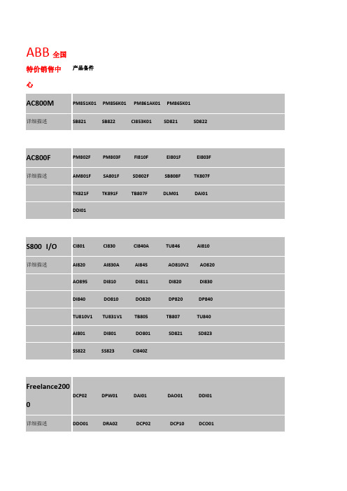
ABB全国特价销售中心
产品备件
AC800M
编程工具
HPC401、SD1、CONF401、HPC301
总线302系列
LD302、LD292、TT302、IF302、FI302、FP302、FY302、SB302
型号
描述
控制器主单元
PM802F
8M
PM803F
16M
型号
描述
电源模件
SA801F
220VAC
SA811F
SD802F
24VDC
SD812F
TU811V1
紧凑型模件端子板 绝缘电压250V,16个信号端子
TU812V1
紧凑型模件端子板 25孔D型接头
TU814V1
紧凑型模件端子板 2*8个信号端子
TU830V1
扩展型模件端子板 绝缘电压50V,2*16个信号端子,24VDC
pizzato

FR1017 意大利PIZZATO安全开关 FD1025 意大利PIZZATO安全开关 FK315 FL1025 意大利PIZZATO安全开关 FX1030 FM1033 FP1025 FS1896D024-F2 FW3392-D8M2 意大利PIZZATO安全开关 FA4108-2DN FG60AD1D0Z-F22 MKF11D09 意大利PIZZATO安全开关 MS20 意大利PIZZATO安全开关 NAB020EE-DN2 PX10200 VFAF-IF1GR05 意大利PIZZATO安全开关 CSAR-02V230 FZ1033 FF4111-KDM
FR1012 意大利PIZZATO传感器 FD1015 意大利PIZZATO传感器 FK307-X FL1015 意大利PIZZATO传感器 FX1015 FM1015 FP1015 CSFS-23VU24 FW2092-M2 意大利PIZZATO传感器 FA4101-5DG FG60AD1D0B-F21 MKF11D02 意大利PIZZATO传感器 MS09 意大利PIZZATO传感器 NAB020BE-DN2 PX10111 VFAF-CA5 意大利PIZZATO传感器 CSAR-01X024 FZ1015 FF4108-KDM
杨昌济体育思想研究

21 0 0年 1月
军 事 体 育 进 修 学 院 学 报
J u n l fP o r a LA n t ueO h s a d ct n o Isi t fP yi l u ai t c E o
Vo .9 No 1 12 .
Jn 0 0 a .2 1
形成了适应当时的社会潮流 ,蕴涵爱 国主义、民主 湖南长沙人。杨 昌济生活在 1 世纪末 2 9 0世纪初 的 主义精神的教育思想。杨 昌济的体育思想是其教育 中国,正是维新与守 旧、革命与反 动两种势力激烈 思想有机组成部分 ,对毛泽东早期 的体育思想 的形
杨 昌 济 (8 1 12 ) 17 ~ 90 ,字 华 生 ,又 名 怀 中 ,
LI S uqo g Z NG J nxa U h -i HA u - i n n
(i g oma Un esyN nhn 3 0 2 C ia J n - N r l i ri ae ag3 0 2 , hn ) a A v t
Abt c: a gC a g—j’ h s a e ua i el y w a an rm d a cd e u ai e l y o etr s a tY h n r n isp y i l d c t n i o g h t er sf c o d o 1 o a v e d c t n io o fw s n n o d g e
关键 词 杨昌济;体育思想;国家;教育;方法
中图分类号 :G 1 . 829 文 献标 识码 :A 文章编 号:17 ~3 0 (0 0 10 0 —4 6 110 2 1 )0 —0 50
S u y o ng Ch ng—j ’ y ia u a i n I e l g t d fYa a 。 S Ph sc lEd c to d o o y ’ 1
- 1、下载文档前请自行甄别文档内容的完整性,平台不提供额外的编辑、内容补充、找答案等附加服务。
- 2、"仅部分预览"的文档,不可在线预览部分如存在完整性等问题,可反馈申请退款(可完整预览的文档不适用该条件!)。
- 3、如文档侵犯您的权益,请联系客服反馈,我们会尽快为您处理(人工客服工作时间:9:00-18:30)。
Harmonising Rock Engineering and the Environment–Qian&Zhou(eds)©2012Taylor&Francis Group,London,ISBN978-0-415-80444-8 Geomechanical model test of underground caverns in salt rockY.R.Liu,B.Li,F.H.Guan&Q.Y angState Key Laboratory of Hydroscience and Hydraulic Engineering,Tsinghua University,Beijing,China ABSTRACT:The world’s increasing demand for natural gas has made the research on the temporal evolution of storage group damage and the corresponding protection theory of great significance.At present,researches on the overall stability and temporal evolution of underground caverns are relatively few.Relating experimental study has not been reported yet.This paper simulated the injection-production cycles of4-cavern reservoir group under different internal pressure with small block masonry.The variation of the displacement and strain of the bedrock and the cavern group is automatically recorded by the displacement meters and the strain gauges buried in the model.Cavern stability under different gas production process,the failure pressure of the caverns and the impact of mudstone interlayer on cavern stability are analyzed.Subject:Underground storageKeywords:oil reservoir,physical modelling,stability analysis1INTRODUCTIONIn recent years,the world’s demand for natural gas has increased significantly,which made energy security an impor-tant issue.Underground natural gas storage construction is an effective method to ensure the storage security and regulate the seasonal supply-demand contradiction of natural gas.Up to2004,the total number of underground gas storage in the world is610.By2008,in which some gas storages are salt cav-erns.Salt mine is the world’s major media for energy reserves because of its good sealing,low permeability and self-healing. Gas storages in Europe and the United States are mainly sin-gle caverns in thick salt dome.However,Salt rocks in China have shallow buried depth,small strata thickness and plenty of insoluble intercalations.To improve the security and space utilization of energy reserve,intensive cavern groups must be used.Thus,it is of great significance to research the tempo-ral evolution of storage group damage and the corresponding protection theory.A large number of researches on the feasibility and safety of gas storages in salt rock have been done.Berest P and Fokker P A studied the mechanical behavior of salt cavern; Favert F summarized the researches on underground gas stor-ages and forecast its development directions.Y ang Chunhe demonstrated the feasibility of underground storage construc-tion by conducting creep tests and numerical simulation of salt rock.Wu Wen put forward several stability evaluation criteri-ons including not allowed spalling,not allowed creep damage, security pillar criterion and land subsidence criterion.The experimental and theoretical research of salt rock’s mechanical properties is the base of storage group stabil-ity analysis.Many scholars abroad,such as Hansen F D, Hunsche U,SkrotzkiW and HampleA,have carried out related researches.Y ang Chunhe,Wu Wen and LiYinping et al carried out a large number of experimental research and theoreti-cal analysis.Y ang Chunhe et al summarized the results.Dai Y onghao et al performed geomechanical model test simulating single caverns of Jintan salt storage.The results of the model test and the numerical simulation are contrasted to analysis the creep deformation and stress distribution of the caverns during operation.At present,researches on the overall stability and temporal evolution of underground caverns are relatively few.The sta-bility of caverns is mainly analyzed with numerical methods. Experimental study mainly focused on the mechanical proper-ties of rock salt and the surrounding rock stability of the single cavern.Experimental study on overall stability and chain destruction of cavern groups has not been reported yet.The3D geomechanical test in this paper simulates gas injection and production of4-cavern group under different pressure.The variation of the caverns’displacement and strain under differ-ent pressure is automatically recorded by displacement meters and strain gauges buried inside the model.The allover stability and the possibility of chain damage are analyzed based on the experimental results.2SIMILITUDE THEOR Y OF RUPTURE TESTING AND SIMULATION OF SALT ROCK MASS2.1Principles of similitudeA geomechanical test is a non-linear destruction test.It must meet the requirement of similarity:1)Geometry similar:the geometry and discontinuous struc-ture of the model should be geometric similar to that of the prototype.2)Stress-strain similar:the deformation modulus,stress-strain relationship and compressive(tensile)strength of the model and the prototype should meet the similarity condi-tion.The stress-strain similar condition is matched in the whole process,as shown in Figure1.According to the result of dimensional analysis,similar conditions need to meet the followingrelations.Figure1.Stress-strain relation of prototype and model.C E,Cγ,C L,Cµ,Cε,C f,Cσ,Cτ,C C,Cδand C F are the ratio of the elastic modulus,density,geometric length,Pois-son’s ratio,strain,friction coefficient,stress,shear strength, cohesion,displacement and load.To ensure the test is normal, Cγ=1.The geometric ratio C L is the determined parameter of the test,other parameters can be obtained with equation(2),(3) and(4).2.2The masonry technology of the modelSmall block masonry is an important method of geomechani-cal model construction.Similar material is pressed into small blocks,which will be glue into a model.The small blocks are to simulate the deformation characteristics of the rock.And the bonding among the small blocks is to simulate the strength properties of fractures.Thus,small block masonry method can simulate both deformation and strength characteristics of the rocks.In the geomechanical model test,both the mechanical parameters of a single small block and the integrated deforma-tion characteristics of the masonry need to be tested to ensure the similarity.Tests show that the deformation modulus of the model is lower than that of the continuous rock by30%to50%. In order to avoid excessive deformation modulus reduction, the block size should be large enough.E.Fumagalli proposed that the masonry block size should be checked with mechan-ical tests of masonry including at least100blocks.The size of blocks used in this experiment is2cm–5cm,as shown in Figure2.Non-continuous structural surfaces,such as muddy inter-calation,etc.,are simulated with dehydrated gypsum.3EXPERIMENTAL SIMULATION3.1Simulation rangeThis test simulates4underground reservoirs;each one is simulated as an ellipsoid with the same size:the length of the semi-major axis is84m,and the length of the semi-minor axis is36m.The ellipsoid centers are in the same horizon-tal plane,located at the vertices of a square with side length 144m.At the bottom of the cavern is sediment area with a height of56m.So the actual height of the cavern is112m. 24m above the center of the cavern is a muddy intercalation with a thickness of2m.the buried depth of the caverns is 1000m.Figure2.Blocks of varioussizes.Figure3.Longitudinal profiles of themodel.Figure4.Cross sectional drawing of the model.The size of the test cell is1.5m×1.5m×1.4m,as shown in Figure5.Schematic diagram of the whole test system is shown in Figure6.3.2Loading systemThe test load is divided into two parts:First,simulate the weight load of776m of rock;second,simulate the pressure variation during the gas injecting and production.The weight load can be calculated by formula(5).Load with self-made jack,using the pad between the model and the jack as transition as shown ih Figure7.Figure 5.Steel testcell.Figure 6.Schematic diagram of experimentaldevice.Figure 7.Loading device for weight stress.The internal pressure is simulated with silicone balloons.The balloons are put into the cavern before capping,as shown in Figure 8.The balloon is connected to the filling equipment outside with the high-strength hose buried in the model,as shown in Figure 9.The balloon is connected with a balance cylinder.With the help of the high precision barometer con-nected with the balance cylinder,the internal pressure of the balloon can be precisely controlled.3.3Data measurement systemThe relative displacement between the cavern walls,the abso-lute displacement and the strain on the cavern wallareFigure 8.Silicone balloons in thecavern.Figure 9.Gaschannel.Figure 10.The layout of displacement meter and the strain gauge (longitudinal profile).measured.The layout of displacement meter and the strain gauge is shown in Figure 10and Figure 11.There are also some internal displacement meters arranged in the mudstone interlayer to measure the interlayer disloca-tion.The self-made displacement meter is made from the man-ganese copper,with strain gauges pasted on both sides.The absolute displacement is fixed outside the model with dis-placement rod.To avoid the impact of the model on the displacement rod,the rod is wrapped with casing pipe,and the contact of the rod and the casing should be avoided.The displacement meter rod and casing are made of plastic pipe and steel pipe.3.4Test scheme5kinds of cycles with different maximum pressure were carried out,that is,12MPa,18MPa,24MPa,28MPa and 36MPa.For each cycle,the loading process was as follows:1)Weight simulation:simulate the weight of 776m rocks above the model with surface force.The loading step wasFigure11.The layout of displacement meter and the strain gauge (cross section).2MPa,added from0MPa to7.78MPa.The load–unload–load process was adopted in order to compact the model.2)4caverns production.Internal pressure of4caverns variedat the same time.The load step was1MPa.3)3caverns production.Internal pressure of3caverns variedat the same time.The load step was1MPa.The inter-nal pressure of all4caverns was raised to the maximum pressure by1MPa.Then3of them began to decompress.4)2adjacent caverns production.Internal pressure of2adja-cent caverns varied at the same time.The load step was 1MPa.The internal pressure of all4caverns was raised to the maximum pressure by1MPa.Then2adjacent caverns began to decompress.5)Single cavern production.The load step was1MPa.The internal pressure of all4caverns was raised to the maximum pressure by1MPa.Then1cavern began to decompress.6)2diagonal caverns production.The load step was1MPa.The internal pressure of all4caverns was raised to the maximum pressure by1MPa.Then2diagonal caverns began to decompress.4RESULTS ANAL YSIS4.1Cavern stability analysis under different gasproduction process.Displacement curves of displacement meter1and9under dif-ferent internal pressures are shown in Figure12and Figure13. Take the positive direction of the x-axis as displacement meter 1’s positive direction,and the negative direction of the y-axis as displacement meter9’s positive direction.The figures showed that gas production of single cavern is the most dangerous gas production process.The risk level order of5different gas production processes in the sequence of descending was:single cavern,2diagonal caverns,2adjacent caverns,3caverns,4caverns.4.2The failure pressure of the cavernsThe internal pressure and displacement curve of displacement meter1during gas injection is shown in Figure14.The failure pressure is28MPa.Figure12.Displacement curves of displacement meter9under different internal pressures(12MPa).Figure13.Displacement curves of displacement meter1under different internal pressures(18MPa).Figure14.The internal pressure and displacement curve of dis-placement meter1during gas inject ion(18MPa).Other internal pressure displacement curves show that displacement2,3,9and10were not damaged,while dis-placement4,5,7and8were damaged at28MPa.4.3The impact of mudstone interlayer on cavern stability The curve of mudstone interlayer relative displacement and the internal pressure(at the position of displacement meter 9)is shown in Figure15.The dislocation of the mudstone interlayer with the maximum pressure36MPa is very small.Figure15.The curve of mudstone interlayer relative displacement and the internal pressure(at the position of displacement meter9). Thus the impact of mudstone interlayer on cavern stability is limited.5CONCLUSIONThis experiment simulated the injection-production cycles of 4-cavern reservoir group with different internal pressure.The variation of the displacement and strain of the bedrock and the cavern group is automatically recorded by the displace-ment meters and the strain gauges buried in the model.The following conclusions can be drawn:1)The risk level order of different gas production processes inthe sequence of descending was:single cavern,2diagonal caverns,2adjacent caverns,3caverns,4caverns.2)The curves of the internal pressure and the displacementduring the production showed that the critical pressure of the model is28MPa.3)The dislocation of the mudstone interlayer with the max-imum pressure36MPa is very small.Thus the impact of mudstone interlayer on cavern stability is limited. ACKNOWLEDGMENTThis work was supported by National Basic Research Pro-gram of China with Grant No.2009CB724604,China National Funds for Distinguished Y oung Scientists(Grant No.50925931)and Project2009THZ01001of Tsinghua University.REFERENCESBerest P.,Brouard B.&Durup G.1996.Behavior of sealed solution-mined caverns.Proc.EURock/96on Prediction and Per-formance in Rock Mechanics and Rock Engineering:1127–1131.Rotterdam:Balkema.Du,Y.J.1996.Research status and development trend of geomechan-ical model test.W ater Resources and Water Engineering.7(02): 64–67.(in Chinese)Dai,Y.H.et al.2009.A study of model test of Jintan rock salt gas storage’s operation.Rock and Soil Mechanics.30(12):3574–3580.(in Chinese)Fumagalli E.1973.Statical and geomechanical models.New Y ork: Springer.Fokker P.A.1995.The behavior of salt and salt caverns[R].Proefschrift:Technische Universiteit Delft.Favert F.2003.Up to now researches and future trends in underground gas storage facilities:a state of the art review.Security of Natural Gas Supply through Transit Countries.[s.l.]:[s.n.]:2003:22–24. Hansen F.D.et al.1984.Elastic behavior of salt.Proceedings of the First Conference on the Mechanical Behavior of Salt:71–83.Clausthal-Zellerfeld:Trans Tech Publications.Hunsche U.1984.Fracture experiments on cubic rock salt samples.Proceedings of the First Conference on the Mechanical Behavior of Salt:169–179.Clauathal-Zellerfeld:Trans Tech Publications. Hunsche U.,Albrecht H.1990.Results of true triaxial strength tests on rock salt.Engineering Fracture Mechanics.35(4/5):867–877. Hunsche U,Hampel A.1999.Rock salt the mechanical proper-ties of the host rock material for a radioactive waste repository.Engineering Geology.52(3/4):271–291.Hample A.et al.1998.Description of the creep rock salt with the composite model-II steady-state creep.Proceedings of the 4th Conference on the Mechanical Behavior of Salt:287–299.Clausthal-Zellerfeld:Trans Tech PublicationsLi,Y.P.&Y ang,C.H.2006.Three-dimensional expanded Cosserat medium constitutive model for laminated salt rock.Rock and Soil Mechanics.27(04):509–513.(in Chinese)Li,Y.P.et al.2007.Direct shear tests for layered salt rocks ofYunying salt mine in Hubei province.Chinese Journal of Rock Mechanics and Engineering.26(09):1767–1772.(in Chinese)Shen,T.2001.Development of geomechanic model experiment tech-niques.Journal of Y angtze River Scientif ic Research Institute.18(05):32–36.(in Chinese)SkrotzkiW.1984.An estimate of the brittle to ductile transition in salt.Proceedings of the First Conference on the Mechanical Behavior of Salt:381–388.Clausthal-Zellerfeld:Trans Tech Publications. Wu,W.et al.2004.Investigation on the constitutive relationship and equation of state for rock salt under impact loading.Chi-nese Journal of Geotechnical Engineering.26(03):367–372.(in Chinese)Wu,W.et al.2004.Testing studies on response behavior of rock salt to impacting.Chinese Journal of Rock Mechanics and Engineering.23(21):3613–3620.(in Chinese)Wu,W.et al.2005.Investigations on evaluationg criteria of stabilities for energy(petroleum and natural gas)storage caverns in rock salt.2005.Chinese Journal of Rock Mechanics and Engineering.24(14):2497–2505.(in Chinese)Y ang,C.H.et al.2002.Investigation on creep damage constitu-tive theory of salt rock.Chinese Journal of Rock Mechanics and Engineering.21(11):1602–1604.(in Chinese)Y ang,C.H.et al.2004.Experiment studies and theoretic analysis of time dependent properties of rock salt.Journal of Liaoning Technical University.23(06):764–766.(in Chinese)Y ang,C.H.et al.2000.Stress level and load ing path effect on time dependent properties of salt rock.Chinese Journal of Rock Mechanics and Engineering.19(03):270–275.(in Chinese)Y ang,C.H.et al.2005.Investigation on possibility of energy storage in salt rock in China.Chinese Journal of Rock Mechanics and Engineering.24(24):4409–4417.(in Chinese)Y ang,C.H.et al.2008.Advances in researches of the mechanical behaviors of bedded salt rocks.Advances in mechanics.30(12): 3553–3561.(in Chinese)Y ang,C.H.et al.2009.Stability and chain destruction analysis of underground energy storage cluster based on deformation rein-forcement theory.Rock and Soil Mechanics.30(12):3553–3561.(in Chinese)Zhang,Y.M.et al.2008.Abroad advances in underground gas storage.Petroleum Technology Forum.(04):29–33.(in Chinese) Zhou,W.Y.&Y ang,R.Q.1979.A research of rock“block model”in calculating the stability of dam abutments by means of finite element method and experiments.1979.Journal of Hydroelectric Engineering.1982(01):53–65.(in Chinese)。