MAGNETICALLY COUPLED ACCESSORY FOR A SELF-PROPELLED DEVICE
磁共振(磁谐振耦合)无线充电技术鼻祖级文章-英文原文

Wireless Power Transfer via Strongly Coupled Magnetic ResonancesAndré Kurs,1* Aristeidis Karalis,2 Robert Moffatt,1 J. D. Joannopoulos,1 Peter Fisher,3Marin Soljačić11Department of Physics, Massachusetts Institute of Technology, Cambridge, MA 02139, USA. 2Department of Electrical Engineering and Computer Science, Massachusetts Institute of Technology, Cambridge, MA 02139, USA. 3Department of Physics and Laboratory for Nuclear Science, Massachusetts Institute of Technology, Cambridge, MA 02139, USA.*To whom correspondence should be addressed. E-mail: akurs@Using self-resonant coils in a strongly coupled regime, we experimentally demonstrate efficient non-radiative power transfer over distances of up to eight times the radius of the coils. We demonstrate the ability to transfer 60W with approximately 40% efficiency over distances in excess of two meters. We present a quantitative model describing the power transfer which matches the experimental results to within 5%. We discuss practical applicability and suggest directions for further studies. At first glance, such power transfer is reminiscent of the usual magnetic induction (10); however, note that the usual non- resonant induction is very inefficient for mid-range applications.Overview of the formalism. Efficient mid-range power transfer occurs in particular regions of the parameter space describing resonant objects strongly coupled to one another. Using coupled-mode theory to describe this physical system (11), we obtain the following set of linear equationsIn the early 20th century, before the electrical-wire grid, Nikola Tesla (1) devoted much effort towards schemes to a&m(t)=(iωm-Γm)a m(t)+∑iκmn a n(t)+F m(t)n≠m(1)transport power wirelessly. However, typical embodiments (e.g. Tesla coils) involved undesirably large electric fields. During the past decade, society has witnessed a dramatic surge of use of autonomous electronic devices (laptops, cell- phones, robots, PDAs, etc.) As a consequence, interest in wireless power has re-emerged (2–4). Radiative transfer (5), while perfectly suitable for transferring information, poses a number of difficulties for power transfer applications: the efficiency of power transfer is very low if the radiation is omnidirectional, and requires an uninterrupted line of sight and sophisticated tracking mechanisms if radiation is unidirectional. A recent theoretical paper (6) presented a detailed analysis of the feasibility of using resonant objects coupled through the tails of their non-radiative fields for mid- range energy transfer (7). Intuitively, two resonant objects of the same resonant frequency tend to exchange energy efficiently, while interacting weakly with extraneous off- resonant objects. In systems of coupled resonances (e.g. acoustic, electro-magnetic, magnetic, nuclear, etc.), there is often a general “strongly coupled” regime of operation (8). If one can operate in that regime in a given system, the energy transfer is expected to be very efficient. Mid-range power transfer implemented this way can be nearly omnidirectional and efficient, irrespective of the geometry of the surrounding space, and with low interference and losses into environmental objects (6).Considerations above apply irrespective of the physical nature of the resonances. In the current work, we focus on one particular physical embodiment: magnetic resonances (9). Magnetic resonances are particularly suitable for everyday applications because most of the common materials do not interact with magnetic fields, so interactions with environmental objects are suppressed even further. We were able to identify the strongly coupled regime in the system of two coupled magnetic resonances, by exploring non-radiative (near-field) magnetic resonant induction at MHzfrequencies. where the indices denote the different resonant objects. The variables a m(t) are defined so that the energy contained in object m is |a m(t)|2, ωm is the resonant frequency of thatisolated object, and Γm is its intrinsic decay rate (e.g. due to absorption and radiated losses), so that in this framework anuncoupled and undriven oscillator with parameters ω0 and Γ0 would evolve in time as exp(iω0t –Γ0t). The κmn= κnm are coupling coefficients between the resonant objects indicated by the subscripts, and F m(t) are driving terms.We limit the treatment to the case of two objects, denoted by source and device, such that the source (identified by the subscript S) is driven externally at a constant frequency, and the two objects have a coupling coefficient κ. Work is extracted from the device (subscript D) by means of a load (subscript W) which acts as a circuit resistance connected to the device, and has the effect of contributing an additional term ΓW to the unloaded device object's decay rate ΓD. The overall decay rate at the device is therefore Γ'D= ΓD+ ΓW. The work extracted is determined by the power dissipated in the load, i.e. 2ΓW|a D(t)|2. Maximizing the efficiency η of the transfer with respect to the loading ΓW, given Eq. 1, is equivalent to solving an impedance matching problem. One finds that the scheme works best when the source and the device are resonant, in which case the efficiency isThe efficiency is maximized when ΓW/ΓD= (1 + κ2/ΓSΓD)1/2. It is easy to show that the key to efficient energy transfer is to have κ2/ΓSΓD> 1. This is commonly referred to as the strongcoupling regime. Resonance plays an essential role in thisDS S D'' power transfer mechanism, as the efficiency is improved by approximately ω2/ΓD 2 (~106 for typical parameters) compared to the case of inductively coupled non-resonant objects. Theoretical model for self-resonant coils. Ourexperimental realization of the scheme consists of two self- resonant coils, one of which (the source coil) is coupled inductively to an oscillating circuit, while the other (the device coil) is coupled inductively to a resistive load (12) (Fig. 1). Self-resonant coils rely on the interplay between distributed inductance and distributed capacitance to achieve resonance. The coils are made of an electrically conducting wire of total length l and cross-sectional radius a wound into Given this relation and the equation of continuity, one finds that the resonant frequency is f 0 = 1/2π[(LC )1/2]. We can now treat this coil as a standard oscillator in coupled-mode theory by defining a (t ) = [(L /2)1/2]I 0(t ).We can estimate the power dissipated by noting that the sinusoidal profile of the current distribution implies that the spatial average of the peak current-squared is |I 0|2/2. For a coil with n turns and made of a material with conductivity σ, we modify the standard formulas for ohmic (R o ) and radiation (R r ) µ0ω l a helix of n turns, radius r , and height h . To the best of our knowledge, there is no exact solution for a finite helix in the literature, and even in the case of infinitely long coils, the solutions rely on assumptions that are inadequate for our R o = 2σ 4πa µ πωr 42 ωh 2 (6)system (13). We have found, however, that the simple quasi- R =0 n 2 + (7)static model described below is in good agreementr ε 12 c3π3 c(approximately 5%) with experiment.We start by observing that the current has to be zero at the ends of the coil, and make the educated guess that the resonant modes of the coil are well approximated bysinusoidal current profiles along the length of the conducting wire. We are interested in the lowest mode, so if we denote by s the parameterization coordinate along the length of the conductor, such that it runs from -l /2 to +l /2, then the time- dependent current profile has the form I 0 cos(πs /l ) exp(i ωt ). It follows from the continuity equation for charge that the linear charge density profile is of the form λ0 sin(πs /l ) exp(i ωt ), so the two halves of the coil (when sliced perpendicularly to its axis) contain charges equal in magnitude q 0 = λ0l /π but opposite in sign.As the coil is resonant, the current and charge density profiles are π/2 out of phase from each other, meaning that the real part of one is maximum when the real part of the other is zero. Equivalently, the energy contained in the coil is 0The first term in Eq. 7 is a magnetic dipole radiation term(assuming r << 2πc /ω); the second term is due to the electric dipole of the coil, and is smaller than the first term for our experimental parameters. The coupled-mode theory decay constant for the coil is therefore Γ = (R o + R r )/2L , and its quality factor is Q = ω/2Γ.We find the coupling coefficient κDS by looking at the power transferred from the source to the device coil,assuming a steady-state solution in which currents and charge densities vary in time as exp(i ωt ).P =⎰d rE (r )⋅J (r ) =-⎰d r (A&S (r )+∇φS (r ))⋅J D (r ) at certain points in time completely due to the current, and at other points, completely due to the charge. Usingelectromagnetic theory, we can define an effective inductance L and an effective capacitance C for each coil as follows:=-1⎰⎰d r d r ' µJ &S(r ')+ρS(r ') 4π |r -r |ε0≡-i ωMI S I Dr '-r|r '-r |3⋅J D (r )(8)L =µ04π |I 0 |⎰⎰d r d r 'J (r )⋅J (r ')|r -r '|where the subscript S indicates that the electric field is due to the source. We then conclude from standard coupled-mode theory arguments that κDS = κSD = κ = ωM /2[(L S L D )1/2]. When 1 1 ρ(r )ρ(r ') the distance D between the centers of the coils is much larger= C 4πε 0 |q 0 | ⎰⎰d r d r ' |r -r '|(4)than their characteristic size, κ scales with the D -3dependence characteristic of dipole-dipole coupling. Both κ and Γ are functions of the frequency, and κ/Γ and the where the spatial current J (r ) and charge density ρ(r ) are obtained respectively from the current and charge densities along the isolated coil, in conjunction with the geometry of the object. As defined, L and C have the property that the efficiency are maximized for a particular value of f , which is in the range 1-50MHz for typical parameters of interest. Thus, picking an appropriate frequency for a given coil size, as we do in this experimental demonstration, plays a major role in optimizing the power transfer.1 2Comparison with experimentallydeterminedU =2 L |I 0 |parameters. The parameters for the two identical helical coils built for the experimental validation of the power 1 2 transfer scheme are h = 20cm, a = 3mm, r = 30 cm, and n = =2C|q 0 | (5)5.25. Both coils are made of copper. The spacing between loops of the helix is not uniform, and we encapsulate theuncertainty about their uniformity by attributing a 10% (2cm) uncertainty to h . The expected resonant frequency given these22dimensions is f0 = 10.56 ± 0.3MHz, which is about 5% off from the measured resonance at 9.90MHz.The theoretical Q for the loops is estimated to be approximately 2500 (assuming σ = 5.9 × 10⁷ m/Ω) but the measured value is Q = 950±50. We believe the discrepancy is mostly due to the effect of the layer of poorly conductingcopper oxide on the surface of the copper wire, to which the current is confined by the short skin depth (~20μm) at this frequency. We therefore use the experimentally observed Q and ΓS= ΓD= Γ = ω/2Q derived from it in all subsequent computations.We find the coupling coefficient κ experimentally by placing the two self-resonant coils (fine-tuned, by slightly adjusting h, to the same resonant frequency when isolated) a distance D apart and measuring the splitting in the frequencies of the two resonant modes. According to coupled-mode theory, this splitting should be ∆ω = 2[(κ2-Γ2)1/2]. In the present work, we focus on the case where the two coils are aligned coaxially (Fig. 2), although similar results are obtained for other orientations (figs. S1 and S2).Measurement of the efficiency. The maximum theoretical efficiency depends only on the parameter κ/[(L S L D)1/2] = κ/Γ, which is greater than 1 even for D = 2.4m (eight times the radius of the coils) (Fig. 3), thus we operate in the strongly- coupled regime throughout the entire range of distances probed.As our driving circuit, we use a standard Colpitts oscillator whose inductive element consists of a single loop of copper wire 25cm in radius(Fig. 1); this loop of wire couples inductively to the source coil and drives the entire wireless power transfer apparatus. The load consists of a calibrated light-bulb (14), and is attached to its own loop of insulated wire, which is placed in proximity of the device coil and inductively coupled to it. By varying the distance between the light-bulb and the device coil, we are able to adjust the parameter ΓW/Γ so that it matches its optimal value, given theoretically by (1 + κ2/Γ2)1/2. (The loop connected to the light-bulb adds a small reactive component to ΓW which is compensated for by slightly retuning the coil.) We measure the work extracted by adjusting the power going into the Colpitts oscillator until the light-bulb at the load glows at its full nominal brightness.We determine the efficiency of the transfer taking place between the source coil and the load by measuring the current at the mid-point of each of the self-resonant coils with a current-probe (which does not lower the Q of the coils noticeably.) This gives a measurement of the current parameters I S and I D used in our theoretical model. We then compute the power dissipated in each coil from P S,D=ΓL|I S,D|2, and obtain the efficiency from η = P W/(P S+ P D+P W). To ensure that the experimental setup is well described by a two-object coupled-mode theory model, we position the device coil such that its direct coupling to the copper loop attached to the Colpitts oscillator is zero. The experimental results are shown in Fig. 4, along with the theoretical prediction for maximum efficiency, given by Eq. 2. We are able to transfer significant amounts of power using this setup, fully lighting up a 60W light-bulb from distances more than 2m away (figs. S3 and S4).As a cross-check, we also measure the total power going from the wall power outlet into the driving circuit. The efficiency of the wireless transfer itself is hard to estimate in this way, however, as the efficiency of the Colpitts oscillator itself is not precisely known, although it is expected to be far from 100% (15). Still, the ratio of power extracted to power entering the driving circuit gives a lower bound on the efficiency. When transferring 60W to the load over a distance of 2m, for example, the power flowing into the driving circuit is 400W. This yields an overall wall-to-load efficiency of 15%, which is reasonable given the expected efficiency of roughly 40% for the wireless power transfer at that distance and the low efficiency of the Colpitts oscillator.Concluding remarks. It is essential that the coils be on resonance for the power transfer to be practical (6). We find experimentally that the power transmitted to the load drops sharply as either one of the coils is detuned from resonance. For a fractional detuning ∆f/f0 of a few times the inverse loaded Q, the induced current in the device coil is indistinguishable from noise.A detailed and quantitative analysis of the effect of external objects on our scheme is beyond the scope of the current work, but we would like to note here that the power transfer is not visibly affected as humans and various everyday objects, such as metals, wood, and electronic devices large and small, are placed between the two coils, even in cases where they completely obstruct the line of sight between source and device (figs. S3 to S5). External objects have a noticeable effect only when they are within a few centimeters from either one of the coils. While some materials (such as aluminum foil, styrofoam and humans) mostly just shift the resonant frequency, which can in principle be easily corrected with a feedback circuit, others (cardboard, wood, and PVC) lower Q when placed closer than a few centimeters from the coil, thereby lowering the efficiency of the transfer.When transferring 60W across 2m, we calculate that at the point halfway between the coils the RMS magnitude of the electric field is E rms= 210V/m, that of the magnetic field isH rms= 1A/m, and that of the Poynting vector is S rms=3.2mW/cm2 (16). These values increase closer to the coils, where the fields at source and device are comparable. For example, at distances 20cm away from the surface of the device coil, we calculate the maximum values for the fields to be E rms= 1.4kV/m, H rms= 8A/m, and S rms= 0.2W/cm2. The power radiated for these parameters is approximately 5W, which is roughly an order of magnitude higher than cell phones. In the particular geometry studied in this article, the overwhelming contribution (by one to two orders of magnitude) to the electric near-field, and hence to the near- field Poynting vector, comes from the electric dipole moment of the coils. If instead one uses capacitively-loaded single- turn loop design (6) - which has the advantage of confining nearly all of the electric field inside the capacitor - and tailors the system to operate at lower frequencies, our calculations show (17) that it should be possible to reduce the values cited above for the electric field, the Poynting vector, and the power radiated to below general safety regulations (e.g. the IEEE safety standards for general public exposure(18).) Although the two coils are currently of identical dimensions, it is possible to make the device coil small enough to fit into portable devices without decreasing the efficiency. One could, for instance, maintain the product of the characteristic sizes of the source and device coils constant, as argued in (6).We believe that the efficiency of the scheme and the power transfer distances could be appreciably improved by silver-plating the coils, which should increase their Q, or by working with more elaborate geometries for the resonant objects (19). Nevertheless, the performance characteristics of the system presented here are already at levels where they could be useful in practical applications.References and Notes1. N. Tesla, U.S. patent 1,119,732 (1914).2.J. M. Fernandez, J. A. Borras, U.S. patent 6,184,651(2001).3.A. Esser, H.-C. Skudelny, IEEE Trans. Indust. Appl. 27,872(1991).4.J. Hirai, T.-W. Kim, A. Kawamura, IEEE Trans. PowerElectron. 15, 21(2000).5.T. A. Vanderelli, J. G. Shearer, J. R. Shearer, U.S. patent7,027,311(2006).6.A. Karalis, J. D. Joannopoul os, M. Soljačić, Ann. Phys.,10.1016/j.aop.2007.04.017(2007).7.Here, by mid-range, we mean that the sizes of the deviceswhich participate in the power transfer are at least a few times smaller than the distance between the devices. For example, if the device being powered is a laptop (size ~ 50cm), while the power source (size ~ 50cm) is in thesame room as the laptop, the distance of power transfer could be within a room or a factory pavilion (size of the order of a fewmeters).8. T. Aoki, et al., Nature 443, 671 (2006).9.K. O’Brien, G. Scheible, H. Gueldner, 29th AnnualConference of the IEEE 1, 367(2003).10.L. Ka-Lai, J. W. Hay, P. G. W., U.S. patent7,042,196(2006).11.H. Haus, Waves and Fields in Optoelectronics(Prentice- Supporting Online Material/cgi/content/full/1143254/DC1SOM TextFigs. S1 to S530 March 2007; accepted 21 May 2007Published online 7 June 2007; 10.1126/science.1143254 Include this information when citing this paper.Fig. 1. Schematic of the experimental setup. A is a single copper loop of radius 25cm that is part of the driving circuit, which outputs a sine wave with frequency 9.9MHz. S and D are respectively the source and device coils referred to in the text. B is a loop of wire attached to the load (“light-bulb”). The various κ’s represent direct couplings between the objects indicated by the arrows. The angle between coil D and the loop A is adjusted to ensure that their direct coupling is zero, while coils S and D are aligned coaxially. The direct couplings between B and A and between B and S are negligible.Fig. 2. Comparison of experimental and theoretical values for κ as a function of the separation between coaxially aligned source and device coils (the wireless power transfer distance.) Fig. 3. Comparison of experimental and theoretical values for the parameter κ/Γ as a function of the wireless power transfer distance. The theory values are obtained by using the theoretical κ and the experimentally measured Γ. The shaded area represents the spread in the theoretical κ/Γ due to the 5% uncertainty in Q.Fig. 4. Comparison of experimental and theoretical efficiencies as functions of the wireless power transfer distance. The shaded area represents the theoretical prediction for maximum efficiency, and is obtained by inserting theHall, Englewood Cliffs, NJ, 1984).12.The couplings to the driving circuit and the load donot theoretical values from Fig. 3 into Eq. 2 [with Γκ2/Γ2 1/2 W /ΓD= (1 +have to be inductive. They may also be connected by awire, for example. We have chosen inductive coupling in the present work because of its easier implementation. 13.S. Sensiper, thesis, Massachusetts Institute of Technology(1951).14.We experimented with various power ratings from 5W to75W.15.W. A. Edson, Vacuum-Tube Oscillators (Wiley, NewYork,1953).16.Note that E ≠cμ0H, and that the fields are out of phaseand not necessarily perpendicular because we are not in a radiativeregime.17.See supporting material on Science Online.18.IEEE Std C95.1—2005 IEEE Standard for Safety Levelswith Respect to Human Exposure to Radio FrequencyElectromagnetic Fields, 3 kHz to 300 GHz (IEEE,Piscataway, NJ,2006).19. J. B. Pendry, Science 306, 1353 (2004).20. The authors would like to thank John Pendry forsuggesting the use of magnetic resonances, and Michael Grossman and Ivan Čelanović for technical assistance.This work was supported in part by the Materials Research Science and Engineering Center program of the National Science Foundation under Grant No. DMR 02-13282, by the U.S. Department of Energy under Grant No. DE-FG02-99ER45778, and by the Army Research Officethrough the Institute for Soldier Nanotechnologies under Contract No. DAAD-19-02-D0002.) ]. The black dots are the maximum efficiency obtained from Eq. 2 and the experimental values of κ/Γ from Fig. 3. The red dots present the directly measured efficiency,as described in thetext.。
JULABO PRESTO W40进程系统说明书

Product data sheetPRESTO W40 Process systemJULABO's water-cooled PRESTO W40 process system combines high performance and a very compact design with all the advantages of the PRESTO series for a working temperature range from -40 °C to +250 °C.The highly dynamic temperature control systems PRESTO are designed for high-precision temperature control for a wide range of applications such as reactor vessels or material stress tests. Moreover, by using efficient components, the process systems can compensate exothermic andendothermic reactions exceptionally fast. Permanent internal monitoring and self-lubricating pumps ensure a long life-time. In addition, numerous interfaces offer many remote control possibilities across networks or for integration into higher-level control systems.Product featuresHeating capacity up to 2.7 kWTemperature stability ±0.01 °C ... ±0.05 °C Alarm outputBuilt-in 5.7’’ industrial color touchscreen External Pt100 sensor connectionSecond external Pt100 sensor connection (accessory)Connections for USB, Ethernet, RS232, and Alarm output Analog connections, RS485, Profibus DP (accessory)Pump pressure up to 1.7 bar, max. flow rate 40 l/min RS232RS485 (Accessory)Profibus DP (Accessory)Cooling capacity up to 1.2 kW Cool-down timeMedium: Thermal HL Heat-up timeMedium: Thermal HLPump capacityPerformance values230V/60Hz (Schuko Plug - CEE 7/4 Plug Type F)Heating capacity kW 2.7Viscosity max. cSt50Pump capacity flow rate l/min0 (40)Pump capacity flow pressure psi 1.5 ... 24.7Power consumption A16Heating capacity kW 2.3 Viscosity max. cSt50 Pump capacity flow rate l/min0 (40)Pump capacity flow pressure psi 1.5 ... 18.9 Power consumption A15Technical dataAvailable voltage versionsOrder No.9 421 401Available voltage versions:9421401.33200-230V/50-60Hz (Schuko Plug - CEE 7/4Plug Type F) (R449A)9421401.04230V/50-60Hz (UK Plug Type BS1363A)(R449A)9421401.05230V/50-60Hz (CH Plug Type SEV 1011)(R449A)9421401.14208V/60Hz (Nema N6-20 Plug) (R449A)CoolingCooling of compressor1-stage Water Cooling water temperature range °C35Cooling water pressure max. psi87Cooling water difference pressure psi7.3Cooling water consumption l/min1OtherSound pressure level dbA53Classification Classification III (FL) IP Code IP 21Pump type Centrifugal Pump Pump type Magnetically coupled1ElectronicsInterfaces Alarm output, Ethernet,Modbus, Profibusoptional, REG/EPROGoptional, RS232,RS485 optional, SDmemory card, Standby-Input optional, USB External pt100 sensor connection integrated2nd external Pt100 sensor connection accessory Integrated programmer8x60 steps Temperature control ICCAbsolute temperature calibration 3 Point Calibration Temperature display 5.7" TFT Touchscreen Temperature setting TouchscreenDimensions and volumesInternal usable expansion volume l 2.7 Minimal process volume l 3.5 Active heat exchanger volume l 1.7Temperature valuesSetting the resolution of the temperaturedisplay °C0.01 Working temperature range °C-40 ... +250 Temperature stability °C±0.01 ... ±0.05Weight lbs172Cooling Water Connection in G¾Dimensions in. (W × L × H)13 x 23.2 x 26.4Pump connectionsM24x1.5 maleAmbient temperature °C+5 ... +40Temperature display resolution °C0.01All BenefitsConvenience for several usersAdministrator level for customizing instrument settings, user levels with limited permissions for fast and safe defined access, password protection,all levels adjustable100 % Cooling capacity‘Active Cooling Control’ for cooling availablethroughout the entire working temperature range,fast cool-down even at higher temperaturesIntelligent temperature control.Intelligent cascade control - automatic and self-optimizing adaptation of the PID controlparameters with external stability of +/- 0.05 °C.Full control‘Temperature Control Features’, for individual optimization, access to all important control parameters, additional settings for band limit,limits, co-speedfactor etc.Control of the external applicationExternal Pt100 sensor connection for precise measurement and control directly in the externalapplicationHighest measuring accuracy‘Absolute Temperature Calibration’ for manual compensation of a temperature difference, 3-pointcalibrationIntelligent pump systemReliable and consistent pump capacity,electronically adjustable pump stages or pressure value, automatic adjustment of pump capacity toviscosityMany interfaces.Straight-forward remote control, datamanagement, and integration into process structures. USB, Ethernet, RS232, SD card, and alarm off are permanently integrated. Furtherinterfaces available as accessories.Space-saving footprintAll connections as well supply and exhaust air are located at the front or rear, no venting grids on the sides, units can be placed close to each other orthe applicationContinuous operation up to +40 °CRobust temperature control instrument,continuous operation even at ambienttemperatures of up to +40 °CMaximum safety.Classification III according to DIN12876-1 enables safe operation, even with flammable fluids.Automatic switch-off in the event of hightemperature or low liquid level.Duplicate safetyAdjustable high temperature cut-off for internaltank and for integrated expansion vesselFor flammable bath fluidClassification III (FL) according to DIN 12876-1Quick supportIf an error occurs, the integrated Black-Box function permits fast diagnosis by the JULABOservice team100% Checked.100% testing. 100% quality. Each JULABO Circulator undergoes thorough quality testingbefore leaving the factory.Green technology.Development consistently applied environmentally friendly materials and technologies.JULABO. Quality.Highest standards of quality for a long product life.Touch display. Perfect operation.With the touch display, the user always has an overview of all values and functions. The intuitive and multilingual menu structure enables perfectcontrol.Quick start.Individual JULABO consultation andcomprehensive manuals at your disposal.Satisfied customers.11 subsidiaries and more than 100 partnersworldwide guarantee fast and qualified JULABOsupport.Services 24/7.Around the clock availability. You can find suitableaccessories, data sheets, manuals, case studies,and more at .。
PRESTO A80t Process System (产品名)说明书

Product data sheetPRESTO A80t Process systemAs air- or water-cooled versions, the A80 and W80 units with 2-stage refrigeration unit offer high cooling and heating capacities for lowest temperatures down to -80 °C.Product features• For highly precise, external temperature applications • Rapid heating and cooling• Wide working temperature ranges without changing fluids • Highest performance with small footprint• Space-saving design optimizes space utilization in your lab • Heating capacity up to 3.4 kW • Cooling capacity up to 1.2 kW• 5,7” industrial color TFT touch screen • Ports for USB, Ethernet, RS232, Modbus • SD-Card slot• Analog connections, RS485, Profibus DP (accessory)Technical dataAvailable voltage versionsOrder No.9 420 801.TAvailable voltage versions:9 420 801.07400V/3PNPE/50Hz (Plug 16A CEE)9 420 801.16208-220V/3PPE/60Hz (Without Plug)9 420 801.06230V/3PPE/50Hz (Plug 32A CEE)CoolingCooling of compressor2-stage AirOtherSound pressure level dbA 68Classification Classification III (FL)IP Code IP 20Pump typeCentrifugal Pump Pump type Magnetically coupled1ElectronicsExternal pt100 sensor connection integrated 2nd external Pt100 sensor connection accessory Integrated programmer 8x60 steps Temperature controlICCAbsolute temperature calibration 3 Point Calibration Temperature displayTemperature display 5.7" TFTTouchscreen Temperature settingTemperature settingTouchscreenDimensions and volumesInternal usable expansion volume l 5.6Minimal process volume l 3.9Active heat exchanger volume l 1.7Weight lbs368.2Dimensions in. (W × L × H)16.9 x 25.6 x 49.6Pump connectionsM24x1.5 maleTemperature valuesSetting the resolution of the temperature display °C0.01Working temperature range °C -80.0 ... +250.0Temperature stability °C +/-0.01 ... +/-0.05Ambient temperature °C+5.0 ... +40.0Temperature display resolution °C0.01Performance values400V/3PNPE/50Hz (Plug 16A CEE)400V/3PNPE/50HzHeating capacity kW 3.4Viscosity max. cST50 Refrigerant R507 Filling volume g1140 Global Warming Potential for R5073985 Carbon dioxide equivalent t 4.543 Refrigerant R23 Filling volume g500 Global Warming Potential for R2314800 Carbon dioxide equivalent t7.4 Pump capacity flow rate l/min16 (40)Pump capacity flow pressure psi 4.4 ... 24.7 Power16 A208-220V/3PPE/60Hz (Without Plug)208V/60HzHeating capacity kW 2.8Viscosity max. cST50 Refrigerant R507 Filling volume g1140 Global Warming Potential for R5073985 Carbon dioxide equivalent t 4.543 Refrigerant R23 Filling volume g500 Global Warming Potential for R2314800 Carbon dioxide equivalent t7.4 Pump capacity flow rate l/min15 (38)Pump capacity flow pressure psi 4.4 ... 21.8 Power15 A 220V/60HzHeating capacity kW 3.1Viscosity max. cST50 Refrigerant R507 Filling volume g1140 Global Warming Potential for R5073985 Carbon dioxide equivalent t 4.543 Refrigerant R23 Filling volume g500 Global Warming Potential for R2314800 Carbon dioxide equivalent t7.4 Pump capacity flow rate l/min16 (40)Pump capacity flow pressure psi 4.4 ... 24.7 Power15 A230V/3PPE/50Hz (Plug 32A CEE)230V/3PPE/50HzHeating capacity kW 3.4Viscosity max. cST50Refrigerant R507Filling volume g1140Global Warming Potential for R5073985Carbon dioxide equivalent t 4.543Refrigerant R23Filling volume g500Global Warming Potential for R2314800Carbon dioxide equivalent t 7.4Pump capacity flow rate l/min 16 ... 40Pump capacity flow pressure psi 4.4 ... 24.7Power20 AAll BenefitsTouch display. Perfect operation.With the touch display, the user always has an overview of all values and functions. The intuitive and multilingual menu structureenables perfect control.Convenience for several usersAdministrator level for customizing instrument settings, user levels with limited permissions for fast and safe defined access, passwordprotection, all levels adjustable100 % Cooling capacity‘Active Cooling Control’ for cooling available throughout the entire working temperature range, fast cool-down even at highertemperaturesIntelligent temperature control.Intelligent cascade control - automatic and self-optimizing adaptation of the PID control parameters with external stability of +/- 0.05°C.Full control‘Temperature Control Features’, for individual optimization, access to all important control parameters, additional settings for band limit,limits, co-speedfactor etc.Control from the external applicationExternal Pt100 sensor connection for precise measurement and control directly in theexternal applicationHighest measuring accuracy‘Absolute Temperature Calibration’ for manual compensation of a temperature difference, 3-point calibrationIntelligent pump systemReliable and consistent pump capacity,electronically adjustable pump stages orpressure value, automatic adjustment of pumpcapacity to viscosityMany interfaces.Straight-forward remote control, datamanagement, and integration into process structures. USB, Ethernet, RS232, SD card, and alarm off are permanently integrated. Furtherinterfaces available as accessories.Space-saving footprintAll connections as well supply and exhaust air are located at the front or rear, no venting grids on the sides, units can be placed close to eachother or the applicationContinuous operation up to +40 °CRobust temperature control instrument,continuous operation even at ambienttemperatures of up to +40 °CMaximum safety.Classification III according to DIN12876-1enables safe operation, even with flammable fluids. Automatic switch-off in the event of high temperature or low liquid level.Duplicate safetyAdjustable high temperature cut-off for internaltank and for integrated expansion vesselFor flammable bath fluidClassification III (FL) according to DIN 12876-1Quick supportIf an error occurs, the integrated Black-Box function permits fast diagnosis by the JULABOservice team 100% Checked.100% testing. 100% quality. Each JULABO Circulator undergoes thorough quality testingbefore leaving the factory.Green technology.Development consistently applied environmentally friendly materials andtechnologies.JULABO. Quality.Highest standards of quality for a long productlife.Quick start.Individual JULABO consultation andcomprehensive manuals at your disposal.Satisfied customers.11 subsidiaries and more than 100 partners worldwide guarantee fast and qualifiedJULABO support.Services 24/7.Around the clock availability. You can find suitable accessories, data sheets, manuals,case studies, and more at .。
铁死亡在心血管疾病中的调节途径及作用
syndromes in patients with angiographically normal or nearnormal(non-obstructive)coronary arteries[J].T rends in CardiovascularMedicine,2018,28(8):541-551.[16]SCALONE G,NICCOLI G,CREA F.Editor's Choice-pathophysiology,diagnosis and management of MINOCA:anupdate[J].European Heart Journal Acute Cardiovascular Care,2019,8(1):54-62.[17]RIEBER J,HUBER A,ERHARD I,et al.Cardiac magneticresonance perfusion imaging for the functional assessment ofcoronary artery disease:a comparison with coronary angiographyand fractional flow reserve[J].European Heart Journal,2006,27(12):1465-1471.[18]PEDRIZZETTI G,CLAUS P,KILNER P J,et al.Principles ofcardiovascular magnetic resonance feature tracking andechocardiographic speckle tracking for informed clinical use[J].Journal of Cardiovascular Magnetic Resonance,2016,18(1):1-12.[19]刘敏.心脏磁共振成像技术临床应用及进展[J].中华老年心脑血管病杂志,2021,23(5):449-451.[20]ZOU Q A,ZHENG T A,ZHOU S L,et al.Quantitative evaluation ofmyocardial strain after myocardial infarction with cardiovascularmagnetic resonance tissue-tracking imaging[J].InternationalHeart Journal,2020,61(3):429-436.[21]李坤成,张振.心脏MR特征追踪技术进展及其临床应用[J].中国医学影像技术,2022,38(1):1-5.[22]CARBERRY J,CARRICK D,HAIG C,et al.Persistence of infarctzone T2hyperintensity at6months after acute ST-segment-elevation myocardial infarction:Incidence,pathophysiology,andprognostic implications[J].Circ Cardiovasc Imaging,2017,10(12):e006586-e006586.[23]SONG L S,MA X H,ZHAO X X,et al.Validation of black blood lategadolinium enhancement(LGE)for evaluation of myocardialinfarction in patients with or without pathological Q-wave onelectrocardiogram(ECG)[J].Cardiovascular Diagnosis andTherapy,2020,10(2):124-134.[24]REINSTADLER S J,STIERMAIER T,LIEBETRAU J,et al.Prognostic significance of remote myocardium alterationsassessed by quantitative noncontrast T1mapping in ST-segmentelevation myocardial infarction[J].JACC:CardiovascularImaging,2018,11(3):411-419.[25]KIM R J,ALBERT T S,WIBLE J H,et al.Performance of delayed-enhancement magnetic resonance imaging with gadoversetamidecontrast for the detection and assessment of myocardialinfarction:an international,multicenter,double-blinded,randomizedtrial[J].Circulation,2008,117(5):629-637.[26]万俊义,赵世华.心脏磁共振钆对比剂延迟强化的临床意义及判断预后的价值[J].中国医学影像技术,2012,28(8):1600-1603. [27]VICENTE-IBARRA N,FELIU E,BERTOMEU-MARTÍNEZ V,et al.Role ofcardiovascular magnetic resonance in the prognosis of patientswith myocardial infarction with non-obstructive coronary arteries[J].Cardiovasc Magn Reson,2021,23(1):83.(收稿日期:2022-08-29)(本文编辑邹丽)铁死亡在心血管疾病中的调节途径及作用王世远,李虹摘要阐述铁死亡的调节途径及其在心血管疾病(CVD)中的作用㊂CVD是我国乃至世界人口死亡和影响生活质量的主要原因,目前,经典的细胞死亡不能完全解释CVD的发生㊁发展,铁死亡的发现进一步补充了CVD发生的可能原因,同时,自噬在铁死亡中发挥着重要作用㊂关键词铁死亡;心血管疾病;自噬;综述d o i:10.12102/j.i s s n.1672-1349.2023.15.016心血管疾病(cardiovascular disease,CVD)是指一组包括心脏病㊁血管病㊁心力衰竭㊁心律失常㊁心脏瓣膜病㊁心肌病㊁心内膜炎等的循环系统疾病㊂CVD的预防㊁治疗㊁预后成为世界范围内生命健康的重要问题㊂细胞死亡在CVD的发生中至关重要㊂一般情况下,心肌细胞和血管细胞死于调节性细胞死亡(RCD),而非意外细胞死亡(ACD),铁死亡(ferroptosis)作为RCD中的新成员,补充了CVD的发生,且自噬在其中发挥重要作用㊂了解铁死亡的调节途径及其在CVD 中的作用,为CVD病人获取更大收益㊂1铁及铁死亡铁是一种微量元素,成人体内含有3~5g的总铁,其中2/3以血红蛋白和肌红蛋白的形式存在,近1/3储存在蛋白中即铁蛋白,而细胞外铁仅占全身铁的0.1%作者单位山西医科大学第二医院(太原030001)通讯作者李虹,E-mail:**********************引用信息王世远,李虹.铁死亡在心血管疾病中的调节途径及作用[J].中西医结合心脑血管病杂志,2023,21(15):2799-2802.左右㊂在机体内,补充铁流失的途径主要有两种,一是在脾脏和其他器官巨噬细胞的作用下,吞噬衰老或损伤的红细胞,释放其中的铁到循环中用于合成血红素[1];二是通过饮食摄入铁[2]㊂铁是参与多种生物过程的必需矿物质元素,如血红素合成㊁DNA合成㊁蛋白质合成㊁催化反应㊁细胞呼吸㊁整体代谢等[3-5]㊂机体铁稳态主要依靠铁调素(hepcidin,阻止细胞铁外流作用)-膜铁转运蛋白(FPN)轴来调节[1]㊂CVD的发生与铁的过载或缺乏密切相关㊂目前,细胞死亡可分为ACD和RCD两种形式[6]㊂RCD主要包括:细胞凋亡(apoptosis)㊁自噬(autophagy)㊁坏死性凋亡(necroptosis)㊁细胞焦亡㊁依赖性细胞死亡(parthanatos)㊁内源性细胞死亡(entosis)㊁溶酶体依赖性细胞死亡(lysosome-dependent cell death,LDCD)㊁氧中毒(oxeiptosis)等形式[7]㊂2012年,Dixon等[8]提出一种新型细胞死亡形式,其特点为非凋亡性㊁铁依赖性的,即铁死亡㊂铁死亡作为RCD新的一员,其线粒体具有致密紧凑㊁嵴缺失㊁膜浓缩及外膜破裂的特点[9]㊂其发生过程中,过载铁在细胞内积聚产生活性氧(ROS),氧化多不饱和脂肪酸,造成细胞膜结构的破坏,最终导致细胞死亡[8]㊂研究表明,铁死亡参与CVD㊁神经退行性疾病㊁肿瘤㊁脑卒中㊁中毒性损伤等多种疾病的发生㊂2铁死亡与自噬自噬是生物体内细胞重要的代谢过程,将衰老或损伤的蛋白质㊁细胞器分解成氨基酸和脂肪酸,可进入循环再次被利用和供应能量,以便维持内环境稳态[10]㊂细胞自噬主要分为以下几个过程:初始自体吞噬泡的形成㊁中间自体吞噬泡的形成㊁降解自体吞噬泡的形成[11]㊂按照溶酶体转运方式和生理功能,自噬主要分为巨自噬㊁微自噬㊁分子伴侣介导的自噬[12]㊂已有研究表明,选择性自噬如铁蛋白吞噬㊁脂肪吞噬㊁时钟吞噬㊁分子伴侣介导的自噬等在铁死亡过程中不可或缺[13];自噬的调节因子如Beclin1㊁核因子E2相关因子2(nuclear factor erythroid derived2-like2, Nrf2)㊁信号转导和转录激活因子3(signal transducer and activator of transcription3,STAT3)㊁p53在铁死亡中发挥着重要的调节作用[14]㊂在生物体内,自噬作用的缺乏或过度均会导致不同程度的RCD[15-16]㊂3铁死亡的调节途径3.1铁代谢细胞内的铁稳态取决于铁的吸收㊁利用㊁储存和排泄之间的动态平衡㊂铁具有活跃的氧化还原能力和不成对的电子特点,成为铁死亡重要的基础因素㊂在正常生物机体内,分泌的胃酸将食物中的Fe3+还原为Fe2+,在十二指肠和空肠上段被吸收㊂在芬顿(Fenton)和类芬顿反应中,Fe2+和过氧化氢(H2O2)反应产生大量羟基自由基和脂质过氧化物,最终导致铁死亡[17]㊂血红素加氧酶1(Hmox1)可将血红素降解生成Fe2+,使游离铁水平增加,进一步导致铁死亡的发生[18-19]㊂在铁蛋白吞噬中,核受体共激活因子4 (NCOA4)将铁蛋白转化为细胞内铁的自噬,并产生游离铁[20-22]㊂研究发现,转录因子BTB结构域和CNC 同源物1(BACH1)是铁代谢的调节剂,在铁死亡中发挥一定作用[23]㊂还有研究发现,由铁蛋白应激诱导的Prominin2可抑制铁蛋白细胞的死亡[24]㊂3.2脂质过氧化多不饱和脂肪酸(PUFAs)是构成细胞膜的重要成分,对维持细胞膜的功能起到重要作用,而PUFAs与自由基相互作用发生的脂质过氧化正是铁死亡的主要原因[25]㊂在长链脂酰辅酶A合成酶4(ACSL4)的催化作用下,PUFAs中的花生四烯酸(AA)和肾上腺酸(AdA)分别合成相应的脂酰辅酶AA-CoA和AdA-CoA,参与膜磷脂的合成,其产物在溶血卵磷脂酰基转移酶3 (LPCAT3)的催化作用下,发生酯化反应生成磷脂酰乙醇胺PE-AA和PE-AdA,再被脂氧合酶(LOXs)或细胞色素P450氧化还原酶(POR)氧化成脂质过氧化产物PE-AA-OOH和PE-AdA-OOH[26]㊂正常情况下,这些有害物质可被谷胱甘肽过氧化物酶4(glutathione peroxidase4,GPX4)还原成没有毒性的脂醇;相反,当机体GPX4处于低水平,其抗氧化作用降低,过氧化物产物会过度积累,引起铁死亡的发生[27-29]㊂3.3Xc-谷胱甘肽(GSH)-GPX4途径GSH具有重要的抗氧化和清除自由基的作用,在谷氨酸-半胱氨酸连接酶(GCL)和谷胱甘肽合酶(GSS)的催化作用下,产生谷氨酸㊁半胱氨酸和甘氨酸㊂GSH有两种形式,还原形式(GSH)和氧化二硫化物形式(GSSG),在自由基等条件刺激下,GPX4发挥其抗氧化或催化脂质氢过氧化物的还原作用,将GSH 转化为GSSG,并将脂质过氧化物(L-OOHs)还原为其相应的脂质醇(L-OHs),限制了脂质过氧化在膜中的扩散,从而减少铁死亡的发生[9,30-32]㊂System Xc-是一种胱氨酸/谷氨酸逆向转运蛋白,可促进胱氨酸和谷氨酸在质膜上的交换,合成GSH[33]㊂相关研究表明,当抑制System Xc-时,可进一步抑制GPX4的抗氧化作用,最终发生铁死亡[34]㊂3.4铁死亡抑制蛋白1(FSP1)-辅酶Q10(CoQ10)-NAD(P)H途径FSP1-CoQ10-NAD(P)H途径是一种与Xc-GSH-GPX4通路协同作用的独立系统,其可独立清除过多的脂质过氧化物,抑制铁死亡的发生[35-36]㊂NADPH是除GSH之外的另一种抗氧化化合物,可通过减少脂质ROS来抑制铁死亡;FSP1是一种氧化还原酶,在NAD(P)H作用下,将泛醌(亦称辅酶Q10,CoQ10)还原为泛醇(CoQH2),CoQH2可通过捕获脂质过氧自由基,抑制脂质过氧化和铁死亡的发生[37]㊂CoQH2是甲羟戊酸途径产生的CoQ10还原形式,抑制甲羟戊酸途径可能会减少CoQ10生成量,进而导致铁死亡[38]㊂3.5三磷酸鸟苷环水解酶1(GCH1)-四氢生物蝶呤(BH4)-二氢叶酸还原酶(DHFR)途径GCH1-BH4-DHFR通路是一种独立于Xc-GSH-GPX4途径的通路,在敲除GPX4诱导铁死亡的模型中,GCH1发挥其保护作用,对其他形式的细胞死亡具有选择性[39]㊂GCH1既是BH4的起始酶,又是限速酶,调节着BH4的含量,DHFR可调节BH4的生成[40]㊂BH4是一种内源性自由基捕获抗氧化剂,通过捕获脂质衍生的过氧自由基阻断脂质过氧化,保护脂质膜免受自身氧化[40]㊂因此,可以得出GCH1-BH4-DHFR通路可通过阻断脂质过氧化抑制铁死亡㊂3.6线粒体线粒体的独有特点 电压依赖性阴离子通道(VDAC)是位于线粒体外膜的蛋白质,当这些蛋白细胞越多,发生铁死亡的敏感性就越高[41]㊂线粒体同样参与着铁死亡的发生,其机制还包括胱氨酸饥饿㊁谷氨酰胺分解,升高膜电位和亚铁含量,促进芬顿反应和脂质过氧化发生,最终造成铁死亡[42-43]㊂4铁死亡与心血管疾病4.1动脉粥样硬化(atherosclerosis,AS)AS是一种以脂质代谢异常为特征的病理过程,主要由脂质沉积㊁内皮细胞损伤㊁氧化应激㊁血管平滑肌细胞(VSMC)增殖㊁巨噬细胞转化㊁炎症和免疫功能障碍等引起[44-45]㊂研究表明,抑制铁死亡可通过减轻脂质过氧化和内皮功能障碍缓解AS,在体内,铁死亡抑制剂Fer-1可减轻高脂饮食的ApoE-/-小鼠诱导的AS 和脂质过氧化;体外细胞实验研究表明,Fer-1可改善氧化型低密度脂蛋白(ox-LDL)诱导的铁死亡和内皮功能障碍[46]㊂4.2心肌梗死(myocardial infarction,MI)MI在全世界具有非常高的致死率㊂研究表明,在MI小鼠模型中,MI部位的铁蛋白重链1(FTH1)水平下降,引起游离铁水平升高和氧化应激发生,促进心肌细胞铁死亡,导致心肌细胞死亡和MI发生[47]㊂有研究表明,与正常组织相比,MI组织中GPX4蛋白的数量减少,引起铁死亡,最终导致MI的发生[48]㊂4.3缺血/再灌注损伤(I/R)I/R通常是指急性心肌梗死血管再通最严重的并发症[49]㊂尤其在再灌注阶段,会产生大量的ROS和自由基,引起心肌细胞损伤坏死和铁死亡[50-51]㊂铁死亡抑制剂Liproxstatin-1(Lip-1),通过降低线粒体上的电压依赖性阴离子通道1(VDAC1)㊁ROS水平和增加GPX4水平保护心肌免受I/R损伤[52-53]㊂由此得出,铁死亡可引起I/R损伤[54]㊂4.4心力衰竭(heart failure,HF)HF是大多数CVD的终末阶段,心脏发生重塑由代偿变为失代偿,出现心肌肥厚和纤维化,最终导致心脏功能的下降[55]㊂已有研究表明,在HF中Toll样受体4(TLR4)和NADPH氧化酶4(NOX4)明显上调,而当敲除TLR4和NOX4时可显著抑制自噬和铁死亡,并对抗心脏重塑和改善心脏功能,为治疗HF提供了基础[56]㊂4.5心肌病阿霉素(DOX)是一种常用的第二代蒽环类抗癌药物,具有很强的心肌毒性,最终导致心肌病㊂有研究表明,在DOX小鼠模型中,Nrf2通过增加血红素加氧酶1(heme oxygenase1,Hmox1)的含量,降解血红素,释放游离铁引起铁过载,导致心肌细胞铁死亡[57];而铁死亡抑制剂Fer-1在该模型中能减轻DOX所致心肌病[57]㊂铁死亡可能在糖尿病心肌病(diabetic cardiomyopathy,DCM)中存在一定作用,但目前机制尚不清楚㊂5小结铁死亡作为一种新的调节性细胞死亡形式出现,参与着CVD的发生㊂本研究一方面从铁代谢㊁脂质过氧化㊁Xc-GSH-GPX4途径㊁FSP1-CoQ10-NAD(P)H 途径㊁GCH1-BH4-DHFR通路㊁线粒体来阐明铁死亡的发生,为阻止铁死亡进而引起心血管疾病提供了研究基础;但其他调节途径机制目前尚未明确,例如能量应激(energy stress)㊁热休克蛋白(HSP)等,可成为进一步的研究点㊂另一方面主要阐明了铁死亡在AS㊁MI㊁I/R损伤㊁HF㊁DOX所致心肌病中的作用,为治疗CVD 提供了新的思路㊂参考文献:[1]PAPANIKOLAOU G,PANTOPOULOS K.Systemic iron homeostasis anderythropoiesis[J].IUBMB Life,2017,69(6):399-413.[2]GREEN R,CHARLTON R,SEFTEL H,et al.Body iron excretion inman:a collaborative study[J].The American Journal of Medicine,1968,45(3):336-353.[3]KOBAYASHI M,SUHARA T,BABA Y,et al.Pathological roles ofiron in cardiovascular disease[J].Current Drug Targets,2018,19(9):1068-1076.[4]ABBASPOUR N,HURRELL R,KELISHADI R.Review on iron andits importance for human health[J].Journal of Research inMedical Sciences,2014,19(2):164-174.[5]ALI M K,KIM R Y,BROWN A C,et al.Critical role for ironaccumulation in the pathogenesis of fibrotic lung disease[J].TheJournal of Pathology,2020,251(1):49-62.[6]TANG D L,KANG R,VANDEN BERGHE T,et al.The molecularmachinery of regulated cell death[J].Cell Research,2019,29(5):347-364.[7]王刚,杨飞飞,罗茂.细胞调节性死亡及其机制的研究[J].西南医科大学学报,2021,44(5):511-519.[8]DIXON S J,LEMBERG K M,LAMPRECHT M R,et al.Ferroptosis:an iron-dependent form of nonapoptotic cell death[J].Cell,2012,149(5):1060-1072.[9]LI J,CAO F,YIN H L,et al.Ferroptosis:past,present and future[J].Cell Death&Disease,2020,11(2):88.[10]CÃTANÃC S,ATANASOV A G,BERINDAN-NEAGOE I.Naturalproducts with anti-aging potential:affected targets and molecularmechanisms[J].Biotechnology Advances,2018,36(6):1649-1656.[11]周罗慧,柏亚明,孙毅,等.血管生成过程中的自噬调控作用及自噬信号通路调控机制研究进展[J].山东医药,2021,61(6):108-111.[12]ZHANG X Y,EVANS T D,JEONG S J,et al.Classical andalternative roles for autophagy in lipid metabolism[J].CurrentOpinion in Lipidology,2018,29(3):203-211.[13]LI N,JIANG W Y,WANG W,et al.Ferroptosis and its emergingroles in cardiovascular diseases[J].Pharmacological Research,2021,166:105466.[14]朱婷,范洋.自噬在细胞铁死亡发生中作用机制的研究进展[J].现代肿瘤医学,2021,29(11):1994-1999.[15]NAKA TOGA W A H.Mechanisms governing autophagosome biogenesis[J].Nature Reviews Molecular Cell Biology,2020,21(8):439-458.[16]AMARAVADI R K,KIMMELMAN A C,DEBNATH J.Targetingautophagy in cancer:recent advances and future directions[J].Cancer Discovery,2019,9(9):1167-1181.[17]HASSANNIA B,VANDENABEELE P,VANDEN BERGHE T.Targeting ferroptosis to iron out cancer[J].Cancer Cell,2019,35(6):830-849.[18]T ANG M Z,CHEN Z,WU D,et al.Ferritinophagy/ferroptosis:iron-relatednewcomers in human diseases[J].Journal of CellularPhysiology,2018,233(12):9179-9190.[19]CHANG L C,CHIANG S K,CHEN S E,et al.Heme oxygenase-1mediates BAY11-7085induced ferroptosis[J].Cancer Letters,2018,416:124-137.[20]BUCCARELLI M,MARCONI M,PACIONI S,et al.Inhibition ofautophagy increases susceptibility of glioblastoma stem cells totemozolomide by igniting ferroptosis[J].Cell Death&Disease,2018,9(8):841.[21]HOU W,XIE Y C,SONG X X,et al.Autophagy promotesferroptosis by degradation of ferritin[J].Autophagy,2016,12(8):1425-1428.[22]GAO M H,MONIAN P,PAN Q H,et al.Ferroptosis is anautophagic cell death process[J].Cell Research,2016,26(9):1021-1032.[23]NISHIZAWA H,MATSUMOTO M,SHINDO T,et al.Ferroptosis iscontrolled by the coordinated transcriptional regulation ofglutathione and labile iron metabolism by the transcription factorBACH1[J].Journal of Biological Chemistry,2020,295(1):69-82.[24]BROWN C W,AMANTE J J,CHHOY P,et al.Prominin2drivesferroptosis resistance by stimulating iron export[J].Developmental Cell,2019,51(5):575-586.[25]CASARES D,ESCRIBÁP V,ROSSELLÓC A.Membrane lipidcomposition:effect on membrane and organelle structure,functionand compartmentalization and therapeutic avenues[J].International Journal of Molecular Sciences,2019,20(9):2167. [26]CHENG J,FAN Y Q,LIU B H,et al.ACSL4suppresses glioma cellsproliferation via activating ferroptosis[J].Oncology Reports,2020,43(1):147-158.[27]LATUNDE-DADA G O.Ferroptosis:role of lipid peroxidation,ironand ferritinophagy[J].Biochimica et Biophysica Acta(BBA)-General Subjects,2017,1861(8):1893-1900.[28]KAGAN V E,MAO G W,QU F,et al.Oxidized arachidonic andadrenic PEs navigate cells to ferroptosis[J].Nature ChemicalBiology,2017,13(1):81-90.[29]YAN B,AI Y W,SUN Q,et al.Membrane damage during ferroptosisis caused by oxidation of phospholipids catalyzed by theoxidoreductases POR and CYB5R1[J].Molecular Cell,2021,81(2):355-369.[30]KOPPULA P,ZHUANG L,GAN B Y.Cystine transporter SLC7A11/xCT in cancer:ferroptosis,nutrient dependency,and cancertherapy[J].Protein&Cell,2021,12(8):599-620.[31]SEIBT T M,PRONETH B,CONRAD M.Role of GPX4inferroptosis and its pharmacological implication[J].Free RadicalBiology and Medicine,2019,133:144-152.[32]BAJIC V P,VAN NESTE C,OBRADOVIC M,et al.Glutathioneredox homeostasis and its relation to cardiovascular disease[J].Oxidative Medicine and Cellular Longevity,2019,2019:5028181. [33]CAO J Y,DIXON S J.Mechanisms of ferroptosis[J].Cellular andMolecular Life Sciences,2016,73(11):2195-2209.[34]PRONETH B,CONRAD M.Ferroptosis and necroinflammation,ayet poorly explored link[J].Cell Death and Differentiation,2019,26(1):14-24.[35]DOLL S,FREITAS F P,SHAH R,et al.FSP1is a glutathione-independent ferroptosis susuker[J].Nature,2019,575(7784):693-698.[36]BERSUKER K,HENDRICKS J M,LI Z P,et al.The CoQoxidoreductase FSP1acts parallel to GPX4ppressor[J].Nature,2019,575(7784):688-692.[37]LEI G,Z HUANG L,GAN B Y.Targeting ferroptosis as avulnerability in cancer[J].Nature Reviews Cancer,2022,22(7):381-396.[38]ZHENG J S,CONRAD M.The metabolic underpinnings offerroptosis[J].Cell Metabolism,2020,32(6):920-937. [39]KRAFT V A N,BEZJIAN C T,PFEIFFER S,et al.GTP cyclohydrolase1/tetrahydrobiopterin counteract ferroptosis through lipid remodeling[J].ACS Central Science,2020,6(1):41-53.[40]SOULA M,WEBER R A,ZILKA O,et al.Metabolic determinants ofcancer cell sensitivity to canonical ferroptosis inducers[J].Nature Chemical Biology,2020,16(12):1351-1360.[41]DEHART D N,FANG D A,HESLOP K,et al.Opening of voltagedependent anion channels promotes reactive oxygen speciesgeneration,mitochondrial dysfunction and cell death in cancercells[J].Biochemical Pharmacology,2018,148:155-162. [42]BATTAGLIA A M,CHIRILLO R,AVERSA I,et al.Ferroptosis andcancer:mitochondria meet the iron maiden cell death[J].Cells,2020,9(6):1505.[43]SHIN D,LEE J,YOU J H,et al.Dihydrolipoamide dehydrogenaseregulates cystine deprivation-induced ferroptosis in head andneck cancer[J].Redox Biology,2020,30:101418.[44]WOLF D,LEY K.Immunity and inflammation in atherosclerosis[J].Circulation Research,2019,124(2):315-327.[45]MARCHIO P,GUERRA-OJEDA S,VILA J M,et al.Targeting earlyatherosclerosis:a focus on oxidative stress and inflammation[J].Oxidative Medicine and Cellular Longevity,2019,2019:8563845. [46]BAI T,LI M X,LIU Y F,et al.Inhibition of ferroptosis alleviatesatherosclerosis through attenuating lipid peroxidation andendothelial dysfunction in mouse aortic endothelial cell[J].FreeRadical Biology and Medicine,2020,160:92-102.[47]OMIYA S,HIKOSO S,IMANISHI Y,et al.Downregulation of ferritinheavy chain increases labile iron pool,oxidative stress and celldeath in cardiomyocytes[J].Journal of Molecular and CellularCardiology,2009,46(1):59-66.[48]PARK T J,PARK J H,LEE G S,et al.Quantitative proteomicanalyses reveal that GPX4downregulation during myocardialinfarction contributes to ferroptosis in cardiomyocytes[J].CellDeath&Disease,2019,10(11):835.[49]IBÁÑEZ B,HEUSCH G,OVIZE M,et al.Evolving therapies formyocardial ischemia/reperfusion injury[J].Journal of theAmerican College of Cardiology,2015,65(14):1454-1471. [50]CADENAS S.ROS and redox signaling in myocardial ischemia-reperfusion injury and cardioprotection[J].Free Radical Biologyand Medicine,2018,117:76-89.[51]YAN H F,TUO Q Z,YIN Q Z,et al.The pathological role offerroptosis in ischemia/reperfusion-related injury[J].ZoologicalResearch,2020,41(3):220-230.[52]FENG Y S,MADUNGWE N B,IMAM ALIAGAN A D,et al.Liproxstatin-1protects the mouse myocardium against ischemia/reperfusion injury by decreasing VDAC1levels and restoringGPX4levels[J].Biochemical and Biophysical ResearchCommunications,2019,520(3):606-611.[53]DABKOWSKI E R,WILLIAMSON C L,HOLLANDER J M.Mitochondria-specific transgenic overexpression of phospholipidhydroperoxide glutathione peroxidase(GPx4)attenuates ischemia/reperfusion-associated cardiac dysfunction[J].Free RadicalBiology and Medicine,2008,45(6):855-865.[54]GAO M H,MONIAN P,QUADRI N,et al.Glutaminolysis andtransferrin regulate ferroptosis[J].Molecular Cell,2015,59(2):298-308.[55]DE COUTO G,OUZOUNIAN M,LIU P P.Early detection ofmyocardial dysfunction and heart failure[J].Nature ReviewsCardiology,2010,7(6):334-344.[56]CHEN X Q,XU S D,ZHAO C X,et al.Role of TLR4/NADPHoxidase4pathway in promoting cell death through autophagyand ferroptosis during heart failure[J].Biochemical andBiophysical Research Communications,2019,516(1):37-43. [57]FANG X X,WANG H,HAN D,et al.Ferroptosis as a target forprotection against cardiomyopathy[J].Proceedings of theNational Academy of Sciences of the United States of America,2019,116(7):2672-2680.(收稿日期:2022-07-23)(本文编辑邹丽)。
医护英语考试题及答案

医护英语考试题及答案一、选择题(每题2分,共20分)1. What is the most common symptom of the common cold?A. FeverB. CoughC. Sore throatD. All of the above答案:D2. Which of the following is NOT a vital sign?A. Blood pressureB. PulseC. Respiratory rateD. Body temperature答案:D3. What does the acronym "ICU" stand for?A. Intensive Care UnitB. International Clinical UnitC. Immediate Care UnitD. Inpatient Clinical Unit答案:A4. The term "diabetes" refers to a condition characterized by:A. High blood sugar levelsB. Low blood sugar levelsC. High blood pressureD. High cholesterol levels答案:A5. A patient is said to be "anemic" if they have:A. Too much red blood cellsB. Too few red blood cellsC. Too much white blood cellsD. Too few platelets答案:B6. What is the medical term for a surgical incision?A. IncisionB. AmputationC. BiopsyD. Excision答案:A7. Which of the following is a method of sterilization?A. Washing with soap and waterB. BoilingC. Using alcohol swabsD. All of the above答案:D8. The abbreviation "MRI" stands for:A. Magnetic Resonance ImagingB. Medical Radioactive ImagingC. Multiple Radioactive IndicatorsD. Medical Radio Imaging答案:A9. What is the primary function of the liver?A. To filter bloodB. To produce bileC. To regulate blood sugar levelsD. To produce red blood cells答案:B10. A "thermometer" is used to measure:A. Blood pressureB. Body temperatureC. Respiratory rateD. Pulse答案:B二、填空题(每题1分,共10分)11. The medical term for a broken bone is ____________.答案:fracture12. A person with a severe allergy to penicillin would be given a warning to avoid contact with this medication, known as a(n) ____________.答案:allergy alert13. The abbreviation "HIV" stands for Human Immunodeficiency ____________.答案:Virus14. A healthcare professional who specializes in the diagnosis and treatment of diseases of the heart is called a ____________.答案:cardiologist15. The process of removing waste products from the body is known as ____________.答案:excretion16. A patient's medical history is recorded in their____________.答案:medical record17. The practice of washing hands with soap and water to prevent the spread of disease is called ____________.答案:hand hygiene18. A(n) ____________ is a healthcare professional trained to provide emergency medical services.答案:paramedic19. The abbreviation "OT" stands for Occupational____________.答案:Therapy20. A patient's condition is assessed and monitored throughregular ____________.答案:check-ups三、简答题(每题5分,共30分)21. What are the four stages of the nursing process?答案:The four stages of the nursing process are assessment, planning, implementation, and evaluation.22. Explain the difference between a virus and a bacterium.答案:A virus is a microscopic infectious agent that can only replicate inside the living cells of an organism, while a bacterium is a single-celled microorganism that can exist independently and can be beneficial, neutral, or harmful to humans.23. What is the purpose of a stethoscope in medical practice?答案:A stethoscope is used by healthcare professionals to listen to the sounds produced by the body, such as the heartbeat and breathing, to diagnose or monitor various conditions.24. Describe the role of a registered nurse in a hospital setting.答案:A registered nurse in a hospital setting providesdirect patient care, administers medications, monitors patients' conditions, collaborates with physicians and other healthcare professionals, and educates patients about theirhealth conditions and treatments.四、翻译题(每题5分,共20分)25. 请将以下句子翻译成英文:医生建议他每天服用阿司匹林以预防心脏病。
曲折型微机电正交磁通门传感器有限元仿真分析
第32卷第1期传感技术学报V o l.32 N o. 12019 $1月CHINESEJOURNAL OF SENSORS ANDACTUATORS Jan. 2019Finite Element Simulation Analysis of Meandering Micro-Electro-MechanicalOrthogonal Fluxgate Sensors*YAN LUi,ZH I Shaotao,GU O Lei%FENG Zhu,LEI C hong*,ZH O U Yong"1. S h a n g h a i J ia o T o n g U n iv e r s ity,S h a n g h a i200240, C h in a $2.D e p a r tm e n t o f M ic r o-N a n o E le c tr o n ic s ,S c h o o l o f E le c tr o n ic I n fo r m a tio n a n d E le c tr ic a lE n g in e e r in g,S h a n g h a i 200240, C h in a $3.K e y L a b o r a tr y fo r T h inF ilm a n d M ic r o fa b r ic a tio n o f M in is tr y o f E d u c a tio n,S h a n g h a i 200240, C h in a)A b s t r a c t!O rthogonal fluxgate s ensors have a w id e m easurem ent range o f m agnetic fie ld and lo w requirem ents fo rm easurem ent en viro n m e n t.T hey are w id e ly used in n a v ig a tio n,m etal detection and e xp lo ra tio n. thogonal flluxgate has lo w s e n s itiv ity,w h ic h imposes certain lim ita tio n s on the fu rtlie r developm ent o f its a p p lica tio nfie ld.A novel orthogonal fluxgate sensor w ith m u lti-tu m e d m eandering m agnetic cores is presented in th is pa p e r.A n d the sensor is sim ulated by a three-dim ension al electrom agnetic fie ld fin ite elem ent sim u la t s im u latio n results show that as the nu m be r o f core turns in crea ses,the se n sitivity and the lin e a r r ic fie ld response o f the flluxgate sensor increases sig n ific a n tly together.K e y w o rd s:M E M S;p i a n ar m eandering flluxgate sensor;fin ite elem ent s im u la tio n;orthogonal fluxgate sensor;weakm agnetic fie ld detectionE E A C C:7230 d o i:10C969/j.is s n.l004-1699.2019.01.012曲折型微机电正交磁通门传感器有限元仿真分析*闫丽丽,支绍韬,郭磊,冯竹,雷冲*,周勇(1.上海交通大学,上海200240;2.电子信息与电气工程学院微纳电子学系,上海200240;3.薄膜与微细技术教育部重点实验室,上海200240)+要:正交磁通门传感器具有磁场测量范围广,对测量环境要求低等优点,被广泛应用于导航、金属探测和勘探领域。
基于SS型磁耦合谐振无线电能传输频带序列划分
第48卷第12期电力系统保护与控制Vol.48No.12 2020年6月16日Power System Protection and Control Jun.16,2020DOI:10.19783/ki.pspc.190915基于SS型磁耦合谐振无线电能传输频带序列划分周念成,梁清泉,王强钢,卢伟国(输配电装备及系统安全与新技术国家重点实验室(重庆大学),重庆400044)摘要:磁耦合谐振无线电能传输(MCR-WPT)具有传递功率较大、距离适中、传递效率高等优点。
针对MCR-WPT 中频率资源划分尚未统一的问题,基于两线圈串联-串联(SS)模型的WPT系统,用电路模型分析WPT系统的运行特性,提出了WPT谐振频率范围划分的距离原则。
使不同传递距离范围对应不同谐振频率序列,并结合改进几何均值原则对划分结果进行修正,得到修正后的谐振频率序列推荐值。
同时,为增强WPT对负载变化的适应性,将谐振频率点拓展为工作频段,提出基于负载特性的工作频段确定方法。
再将谐振频率序列和工作频段结合,实现了基于SS型MCR-WPT系统的频带序列划分。
最后搭建实验平台验证频带序列划分结果的合理性。
关键词:无线电能传输;磁耦合谐振;谐振频率;频带序列划分Frequency band sequence allocation of magnetically coupled resonant wirelesspower transmission systems based on SS typeZHOU Niancheng,LIANG Qingquan,WANG Qianggang,LU Weiguo(State Key Laboratory of Power Transmission Equipment&System Security and New Technology,Chongqing University,Chongqing400044,China)Abstract:Magnetically Coupled Resonant Wireless Power Transmission(MCR-WPT)has advantages of large transmission power,moderate distance,and high transmission efficiency,etc.Given that the frequency resource division in MCR-WPT has not been unified,this paper is based on the WPT system of a two-coil Series-Series(SS)model.It analyzes the operating characteristics of a WPT system using a circuit model,and proposes the distance principle of WPT resonance frequency range division,so that different transmission distance ranges correspond to different resonance frequency sequences.It combines with an improved geometric mean principle to correct segmentation results,and the recommended values of the modified resonant frequency sequence are obtained.In order to enhance the adaptability of WPT to load changes,the resonant frequency point is expanded into the working frequency band,and a working frequency band determination method based on load characteristics is proposed.Then the resonant frequency sequence is combined with the working frequency band to complete the frequency band division of the MCR-WPT system based on the SS type.Finally,an experimental platform is built to verify the rationality of the frequency band segmentation results.This work is supported by National Natural Science Foundation of China(No.51877017).Key words:wireless power transmission;magnetic coupling resonance;resonant frequency;frequency band sequence division0引言基于SS型磁耦合谐振方式的无线电能传输是基于近场方式的新型无线电能传输技术,具有高效性、安全性等优点[1]。
永磁涡流耦合器传递转矩计算方法研究

收稿日期:2021-04-19基金项目:国家自然科学基金资助项目(U1808217ꎬ51905077)ꎻ辽宁省 兴辽英才 计划项目(XLYC1807086ꎬXLYC1801008)ꎻ大连市高层次人才创新支持计划项目(2017RJ04ꎬ2019CT01).作者简介:程习康(1993-)ꎬ男ꎬ河南新乡人ꎬ大连理工大学博士研究生ꎻ刘㊀巍(1979-)ꎬ男ꎬ内蒙古赤峰人ꎬ大连理工大学教授ꎬ博士生导师.第42卷第12期2021年12月东北大学学报(自然科学版)JournalofNortheasternUniversity(NaturalScience)Vol.42ꎬNo.12Dec.2021㊀doi:10.12068/j.issn.1005-3026.2021.12.010永磁涡流耦合器传递转矩计算方法研究程习康ꎬ刘㊀巍ꎬ孙明浩ꎬ罗唯奇(大连理工大学机械工程学院ꎬ辽宁大连㊀116024)摘㊀㊀㊀要:永磁涡流耦合器作为一种传动装置ꎬ传递转矩的有效计算是评价其传动性能的重要指标.针对一台6磁极对数㊁额定输入转速1450r/min的永磁涡流耦合器ꎬ首先ꎬ根据耦合器几何结构ꎬ采用有限元方法对磁力线走向进行了仿真分析ꎬ获得永磁涡流耦合器的磁路分布ꎬ进而通过分析漏磁边界条件得到了泄漏磁阻和有效磁动势ꎻ其次ꎬ建立导体盘涡流的坐标系ꎬ根据趋肤深度和安培环路定律ꎬ考虑磁场分布的连续性和对称性ꎬ构建了耦合器的磁感应强度方程ꎻ然后ꎬ根据导体盘涡电流密度和电导率的数学关系ꎬ同时考虑三维端部效应ꎬ得到了传递转矩的解析结果ꎻ最后ꎬ建立样机试验平台和三维有限元模型对该方法进行验证.结果表明ꎬ在一定的转速差范围内ꎬ所提计算方法具有较好的精度ꎬ相对误差在6%以内.采用该方法对永磁涡流耦合器的设计优化提出了一些合理化建议.关㊀键㊀词:永磁涡流耦合器ꎻ磁路ꎻ泄漏磁阻ꎻ传递转矩ꎻ试验中图分类号:TH133 4㊀㊀㊀文献标志码:A㊀㊀㊀文章编号:1005-3026(2021)12-1739-08ResearchonTransmittedTorqueCalculationMethodofPermanentMagnetEddy ̄CurrentCouplersCHENGXi ̄kangꎬLIUWeiꎬSUNMing ̄haoꎬLUOWei ̄qi(SchoolofMechanicalEngineeringꎬDalianUniversityofTechnologyꎬDalian116024ꎬChina.Correspondingauthor:LIUWeiꎬE ̄mail:lw2007@dlut.edu.cn)Abstract:Asakindofdrivingdeviceꎬtheeffectivecalculationoftransmittedtorqueforpermanentmagneteddy ̄currentcouplersisasignificantindextoevaluatethetransmissionperformance.Forapermanentmagneteddycurrentcouplerwith6polepairsand1450r/minratedinputspeedꎬfirstlyꎬaccordingtothegeometryꎬfiniteelementmethodisusedtosimulatethemagneticfieldlinesandtoobtainthemagneticpathdistribution.Alsoꎬthroughtheanalysisofleakagefluxesboundaryconditionꎬtheleakagemagneticresistanceandeffectivemagnetomotiveforceareobtained.Secondlyꎬthecoordinatesystemofeddycurrentontheconductordiskisestablished.Accordingtothelawofskindepthandampereloopꎬthemagneticinductionintensityequationisconstructedwhichconsidersthecontinuityandsymmetryofmagneticfielddistribution.Thenꎬbasedonthemathematicalrelationshipbetweeneddy ̄currentdensityandconductivityoftheconductordiskꎬtheanalyticalresultoftransmittedtorqueispresentedaccountingforthethree ̄dimensionalendeffect.Finallyꎬaprototypetestplatformandathree ̄dimensionalfiniteelementanalyticalmodelarebuilttoverifythemethod.Theresultsshowthattheproposedmethodhasgoodaccuracywithintherangeofspeedslipinacertainoperationwheretherelativeerroriswithin6%.Moreoverꎬsomereasonablesuggestionsareputforwardforthedesignoptimizationofpermanentmagneteddy ̄currentcouplers.Keywords:permanentmagneteddy ̄currentcouplerꎻmagneticpathꎻleakagemagneticresistanceꎻtransmittedtorqueꎻexperiment㊀㊀随着全球经济的高速发展ꎬ目前人类面临着日益严重的环境破坏㊁资源匮乏㊁生态污染等问题ꎬ发展以节能㊁高效㊁环保为理念的清洁绿色产品对人类可持续发展具有重要意义ꎬ永磁涡流耦合器在这种产品理念驱动下产生[1].永磁涡流耦合器作为一种新型的非接触传动装置ꎬ具有结构简单㊁节能高效㊁传动平稳㊁无污染㊁允许主从动轴不对中等特点ꎬ而且具有良好的环境适应性[2-4].与液力耦合器和变频器相比ꎬ液力耦合器可控性差且存在喷油污染ꎬ低速时无法平滑加速ꎻ变频器故障率高㊁环境适应性差ꎬ产生谐波污染进而影响电网ꎬ而永磁涡流耦合器在实现转矩调节和传递的同时ꎬ可有效地规避上述问题ꎬ因此一定程度上可以替代液力耦合器和变频器ꎬ在汽轮机㊁冷却泵㊁皮带运输机㊁大型刮板机㊁破碎机㊁球磨机等重大工程装备中具有较好应用前景[5-7].永磁涡流耦合器最早由美国MagnaDrive公司应用在尼米兹号和斯坦尼斯号航空母舰的海水泵上ꎬ后来扩展到民用行业ꎬ并于2008年引进到中国.近年来ꎬ国内外学者针对永磁涡流耦合器的传递转矩进行了大量的研究.Canova等[8]基于分离变量法将永磁涡流耦合器从三维问题简化为二维ꎬ得到了转矩-转速关系的纯解析模型ꎻ文献[9-11]考虑了材料的磁饱和及永磁体本身特性ꎬ同时考虑了三维结构参数ꎬ建立了一种可处理复杂结构的永磁涡流耦合器传递转矩预测模型ꎬ并将该模型与有限元结果对比ꎬ得到了一致性较好的评价ꎻ文献[12-14]在平均半径处进行线性化假设ꎬ求解了三维麦克斯韦方程ꎬ研究了磁极对数㊁气隙长度等几何参数的影响ꎬ建立了一种新的永磁涡流耦合器传动性能二维解析模型ꎬ并将计算的转矩与有限元和实验结果进行了比较ꎻErasmus等[15]提出了一种求解径向磁通永磁涡流耦合器转矩的半解析计算方法ꎬ考虑了磁通密度谐波的影响ꎬ采用罗素系数顾及了三维端部效应ꎬ通过实验验证了半解析转矩计算方法的正确性.国内针对永磁涡流耦合器的研究起步较晚.杨超君等[16]以层理论为指导ꎬ分析并得到了永磁涡流耦合器的转矩计算方法ꎬ然后通过有限元方法分析三维瞬态磁场的分布ꎬ并得到了关键参数如气隙长度㊁永磁体厚度㊁磁极数㊁从动盘的槽数㊁槽深以及主动转速等对转矩计算结果的影响ꎻ文献[17-18]基于等效磁路法建立了永磁涡流耦合器的解析模型ꎬ分析了永磁涡流耦合器各区域磁导和漏磁ꎬ求解出气隙中的磁感应强度ꎬ进而推导出转矩计算公式ꎻ何富君等[19]利用AnsoftMaxwell仿真软件建立了永磁涡流耦合器三维有限元模型ꎬ对耦合器的传动特性进行仿真研究ꎬ得到传递转矩与间隙㊁转速差之间的对应关系ꎻ李德永等[20]以电磁感应原理为基础ꎬ提出了简化的永磁体阵列三维模型ꎬ基于洛伦兹定律建立了转矩的解析模型ꎬ并和有限元结果进行了对比ꎬ分析了永磁涡流耦合器动态特性的影响因素.与上述研究不同ꎬ本文以一台6磁极对数㊁额定输入转速1450r/min的永磁涡流耦合器为例ꎬ首先以永磁涡流耦合器的三维复杂结构为导向ꎬ提出了一种更加简单且有效的等效磁路模型ꎬ然后基于安培环路定律ꎬ对样机的传递转矩进行解析计算ꎬ最后建立三维有限元模型和实验平台对转矩进行了验证ꎬ与实验结果对比ꎬ计算方法具有较好的精度.1㊀永磁涡流耦合器几何结构及磁路1 1㊀永磁涡流耦合器几何结构永磁涡流耦合器主要由两部分组成:其中一部分是导体转子ꎬ包含导体轭铁和导体盘ꎻ另一部分是磁体转子ꎬ包含磁体盘㊁永磁体和磁体轭铁.电机端连接导体转子并进行旋转ꎬ导体转子切割磁体转子的N/S交替磁场ꎬ根据法拉第电磁感应定律ꎬ导体转子内将产生变化的涡流磁场ꎬ在永磁体本身磁场和涡流磁场的交互下ꎬ实现了电机端到负载端的转矩传递.永磁涡流耦合器几何结构如图1所示ꎬ导体转子和磁体转子之间存在着气隙ꎬ通过改变气隙厚度可以实现转矩大小的调节.此外ꎬ导体轭铁和磁体轭铁的作用是保证磁力线的收敛.图1㊀永磁涡流耦合器几何结构Fig 1㊀Geometricstructureofpermanentmagneteddy ̄currentcouplers图1中ꎬli1为导体轭铁厚度ꎬlcs为导体盘厚度ꎬla为气隙厚度ꎬlp为磁体盘厚度ꎬlpm为永磁体0471东北大学学报(自然科学版)㊀㊀㊀第42卷㊀㊀㊀㊀厚度ꎬli2为磁体轭铁厚度ꎬr2为导体盘外径ꎬr1为导体盘内径ꎬrp2为永磁体外径ꎬrp1为永磁体内径ꎬrav为永磁体平均半径ꎬwpm为永磁体径向宽度ꎬτm为相邻永磁体之间的距离ꎬτp为相邻永磁体中心之间的距离.1 2㊀永磁涡流耦合器磁路永磁涡流耦合器磁路可以有效地表示其磁力线走向ꎬ这是分析并计算传递转矩的重要前提.为了得到这一磁路ꎬ采用有限元方法对永磁涡流耦合器进行了分析.如图2所示ꎬ由于永磁涡流耦合器属于对称结构ꎬ这里只建立了包含一对永磁体的永磁涡流耦合器磁路.①表示永磁涡流耦合器的主磁路ꎬ其磁力线走线为:永磁体ң磁体盘ң导体盘ң导体轭铁ң导体盘ң磁体盘ң永磁体ң磁体轭铁ң永磁体ꎻ②表示永磁涡流耦合器的第一泄漏磁路ꎬ其磁力线走向为:永磁体ң磁体盘ң导体盘ң磁体盘ң永磁体ң磁体轭铁ң永磁体ꎻ③表示永磁涡流耦合器的第二泄漏磁路ꎬ其磁力线走向为:永磁体ң磁体盘ң磁体轭铁ң永磁体.图2㊀永磁涡流耦合器磁路Fig 2㊀Magneticcircuitofpermanentmagneteddy ̄currentcouplers2㊀有效磁通量求解2 1㊀泄漏磁阻求解根据图2的第一泄漏磁路②和第二泄漏磁路③ꎬ可以分别计算出第一泄漏磁阻和第二泄漏磁阻.第一泄漏磁阻主要存在于气隙和导体盘处ꎬ存在如下关系:Rl1=1/(ʏxa0μ0μawpmdxπx+τm)ꎬxa=min[lp-lpm+la+lcsꎬ(τp-τm)/2].}(1)式中:Rl1为第一泄漏磁阻ꎻμ0为真空磁导率ꎻμa空气磁导率ꎻxa为第一漏磁积分边界条件.第二泄漏磁阻主要存在于永磁体本身之间ꎬ存在如下关系:Rl2=1/(ʏxb0μ0μawpmdx2πx+lpm)ꎬxb=min[τm/2ꎬ(τp-τm)/2].}(2)式中:Rl2为第二泄漏磁阻ꎻxb为第二漏磁积分边界条件.根据第一泄漏磁阻和第二泄漏磁阻ꎬ获得总泄漏磁阻和总泄漏磁导的表达式为Rl=1/(Rl1//Rl2)ꎬΛl=1/Rl.}(3)式中:Rl为总泄漏磁阻ꎻΛl为总泄漏磁导.2 2㊀有效磁动势求解在永磁涡流耦合器结构中ꎬ永磁体是可靠的磁源ꎬ负责提供稳定有效的磁场.根据永磁体本身的属性ꎬ可以得到原有磁动势为F0=Hpmlpm.(4)式中ꎬHpm为永磁体矫顽力.类似于电路中电源的内阻ꎬ永磁体本身也存在磁阻ꎬ这个永磁体磁阻的表达式为Rpm=2lpmμ0μpmwpm(τp-τm).(5)式中:Rpm为永磁体磁阻ꎻμpm为永磁体相对磁感应强度.根据磁导与磁阻的关系ꎬ进一步获得永磁体磁导为Λpm=1/Rpm.(6)本质上来说ꎬ由式(3)获得的总泄漏磁导相对于永磁体磁导是一种磁损耗.因此ꎬ根据式(1)~(6)可以获得有效磁动势为Fe=krF0Λl+ΛpmΛpm.(7)式中ꎬkr为有效磁阻修正系数ꎬ其数值按经验获取ꎬ不同的应用场合数值略有不同.2 3㊀有效磁通量求解永磁涡流耦合器各部分都存在磁阻ꎬ导体盘磁阻的表达式为Rcs=2lcsμ0μcswpm(τp-τm).(8)式中ꎬμcs为导体盘相对磁导率.气隙磁阻的表达式为Ra=2laμ0μawpm(τp-τm).(9)磁体盘磁阻为Ri2=2(lp-lpm)μ0μpwpm(τp-τm).(10)式中ꎬμp为磁体盘相对磁感应强度.1471第12期㊀㊀㊀程习康等:永磁涡流耦合器传递转矩计算方法研究㊀㊀㊀㊀导体轭铁磁阻和磁体轭铁磁阻为Ri1=Ri3=min{4li1μ0μi1wpm(τp-τm)+τmμ0μi1wpmli1ꎬ4li2μ0μi2wpm(τp-τm)+τmμ0μi2wpmli2}.(11)式中:Ri1为导体轭铁磁阻ꎻRi2为磁体轭铁磁阻ꎻμi1为导体轭铁相对磁导率ꎻμi2为磁体轭铁相对磁导率.在图2中ꎬ虽然建立了永磁涡流耦合器磁路ꎬ但是该磁路涉及的磁力线路径相对复杂ꎬ不能直接反映出有效磁通.根据上文的分析ꎬ图3建立了一个简单且有效的永磁涡流耦合器等效磁路模型.根据图3建立的等效磁路模型和式(7)获得的有效磁动势ꎬ求得有效磁通量为φe=2Fe2Rcs+2Ra+2Ri2+Ri1+Ri3.(12)图3㊀永磁涡流耦合器等效磁路模型Fig 3㊀Equivalentmagneticcircuitmodelofpermanentmagneteddy ̄currentcoupler3㊀传递转矩模型3 1㊀有效涡流深度永磁涡流耦合器正常运转时ꎬ导体盘和磁体盘之间存在转速差ꎬ促使穿过导体盘的磁通量方向和大小随时间呈现周期性变化.根据法拉第电磁感应定律ꎬ导致导体盘上产生围绕磁通量变化方向的涡流.该涡流并不是完全存在于导体盘内ꎬ而是集中于导体盘表层ꎬ越接近于导体盘表面ꎬ涡电流密度越大ꎬ这一现象被称为趋肤效应.初始趋肤深度为ld0=60πpΔnσcsμ0μcs.(13)式中:p为磁极对数ꎻΔn为导体盘和磁体盘之间的转速差ꎻσcs为导体盘电导率.考虑到涡电流密度在导体盘深度方向(z方向)呈现指数级递减ꎬ涡电流密度和趋肤深度满足方程ʏld00Jez/ld0dz=ʏld0Jdz.(14)式中:J为涡电流密度ꎻld为有效趋肤深度.对式(14)进行求解ꎬ得到有效趋肤深度为ld=(1-1/e)ld0.(15)进一步化简ꎬ得到有效涡流深度为lce=min(lcsꎬld).(16)3 2㊀磁感应强度求解为了更清晰理解建模过程ꎬ在永磁体剖切视图和导体盘视图下ꎬ图4建立了涡流区域的坐标系位置.该坐标系以永磁体正对导体盘的中心为原点ꎬ垂直于导体盘为z方向.图4㊀涡流区域坐标系位置示意图Fig 4㊀Schematicdiagramofeddy ̄currentregionalcoordinatesystemposition当导体盘切割磁力线运动时ꎬ不仅应该考虑永磁体本身磁场ꎬ同时应该考虑涡流产生的感应磁场.因此ꎬ建模时必须将磁感应强度划分为有效磁感应强度和感生磁感应强度ꎬ得到[10]B(y)=Be(y)+Bi(y).(17)式中:B(y)为磁感应强度ꎻBe(y)为有效磁感应强度ꎻBi(y)为感生磁感应强度.其中ꎬ根据式(12)的结果和图4建立的坐标系ꎬ得到有效磁感应强度为Be(y)=Be=2φe/[wpm(τp-τm)]ꎬ㊀㊀㊀|y|ɤ(τp-τm)/2ꎻ0ꎬyɪ[-τp/2ꎬ-(τp-τm)/2]ɣ㊀㊀㊀[(τp-τm)/2ꎬτp/2].ìîíïïïïï(18)涡电流密度和磁感应强度的关系为[10-11]J(y)=σcsΔωravB(y).(19)式中:Δω为导体盘和磁体盘之间的角速度差ꎬΔω=2πΔn/60.根据安培环路定理ꎬ得到ɥcH dl=∯sJ(y)ds⇒ɥcBi(y)μ0dl=∯sσcsΔωravB(y)ds.(20)2471东北大学学报(自然科学版)㊀㊀㊀第42卷㊀㊀进一步对式(20)化简得到2(lp-lpm+la+lce)Bi(y)μ0=σcsΔωravlceˑʏy2y1B(y)dy.(21)对式(21)进一步化简得到㊀Bi(y)=kʏy2y1[Be(y)+Bi(y)]dyꎬ㊀k=μ0σcsΔωravlce/[2(lp-lpm+la+lce)].(22)式中ꎬk为中间变量代号ꎬ使用k是为了让表达式简洁.对式(22)进行微分ꎬ得到dBi(y)=kBe(y)+kBi(y)ꎬyɪ[-τp/2ꎬτp/2].(23)对式(23)进行求解ꎬ得到Bi(y)=Bi1(y)=c1ekyꎬyɪ[-τp/2ꎬ-(τp-τm)/2]ꎻBi2(y)=c2eky-Beꎬyɪ[-(τp-τm)/2ꎬ(τp-τm)/2]ꎻBi3(y)=c3ekyꎬyɪ[(τp-τm)/2ꎬτp/2].ìîíïïïï(24)㊀㊀式(24)中ꎬ必定存在一个y0使得Bi2(y=y0)=0成立ꎬ得到c2=Bee-ky0.(25)由于涡流区域对称分布ꎬ在区间[-τp/2ꎬy0]和区间[y0ꎬτp/2]的涡流大小是一样的ꎬ得到ʏy0-τp/2ʏlce0J(y)dydz=ʏτp/2y0ʏlce0J(y)dydz.(26)根据函数的连续性ꎬ得到Bi1[y=-(τp-τm)/2]=Bi2[y=-(τp-τm)/2]ꎻBi2[y=(τp-τm)/2]=Bi3[y=(τp-τm)/2].}(27)结合式(25)~(27)ꎬy0ꎬc1ꎬc2ꎬc3可以计算得到:y0=-1kln[cosh(kτm/2)/cosh(kτp/2)]ꎻc1=Be[cosh(kτm/2)/cosh(kτp/2)-ek(τp-τm)/2]ꎻc2=Be[cosh(kτm/2)/cosh(kτp/2)]ꎻc3=Be[cosh(kτm/2)/cosh(kτp/2)-e-k(τp-τm)/2].üþýïïïïïï(28)将式(28)代入到式(24)中ꎬ得到Bi(y)=Be[cosh(kτm/2)cosh(kτp/2)-ek(τp-τm)2]ekyꎬyɪ[-τp2ꎬ-(τp-τm)2]ꎻBecosh(kτm/2)cosh(kτp/2)eky-Beꎬyɪ[-(τp-τm)2ꎬ(τp-τm)2]ꎻBe[cosh(kτm/2)cosh(kτp/2)-e-k(τp-τm)2]ekyꎬyɪ[(τp-τm)2ꎬτp2].ìîíïïïïïïïï(29)㊀㊀求得感生磁感应强度后ꎬ磁感应强度可以由式(17)计算获得.3 3㊀传递转矩求解㊀㊀根据式(19)得到的J(y)ꎬ得到单个涡流区域的传递功率为Pone=(1/σcs)∭|J(y)|2dxdydz=(lce/σcs)ʏr2r1dxʏτp/2-τp/2|J(y)|2dy.(30)㊀㊀进一步对式(30)积分得到Pone=lce(r2-r1)r2avσcsΔω2B2e[ek(τp+τm)-ekτm-e2kτm+ekτp]k[ek(τp+τm)+ekτm].(31)㊀㊀考虑到磁极对数的影响ꎬ得到初始传递转矩:T0=2pPoneΔω.(32)如图5所示ꎬ涡流区域被划分为悬垂区和中心区ꎬ只有存在于中心区的涡电流对转矩传递产生实质作用ꎬ这种现象被称为三维端部效应.考虑到这种端部效应[3]ꎬ必须对初始传递转矩进行修正.该修正系数为3471第12期㊀㊀㊀程习康等:永磁涡流耦合器传递转矩计算方法研究㊀㊀kc=1-πwpmtanh(πwpm2τp)2τp1+tanh(πwpm2τp)tanh{[π(r2-r1)-πwpm]2τp}{}.(33)图5㊀三维端部效应Fig 5㊀Three ̄dimensionalendeffect对初始传递转矩修正后ꎬ得到传递转矩为T=kcT0.(34)4㊀试验验证4 1㊀试验平台为了验证本文提出的永磁涡流耦合器传递转矩计算方法ꎬ同时为了弥补实验和有限元方法本身的误差ꎬ建立了如图6所示的传递转矩试验平台和如图7所示的三维有限元分析模型.其中ꎬ三相异步电机是试验平台的动力源ꎬ其额定输入转速为1450r/min.转矩转速传感器分别设置在电机端和负载端ꎬ可有效测量永磁涡流耦合器的转速差和转矩.气隙调节器可以改变永磁涡流耦合器导体盘和磁体盘之间的气隙大小ꎬ其调节范围为4~30mm.图6㊀永磁涡流耦合器试验平台Fig 6㊀Testplatformforpermanentmagneteddy ̄currentcoupler图7㊀三维有限元分析模型Fig 7㊀3Dfiniteelementanalyticalmodel同时ꎬ设置了所制作的永磁涡流耦合器样机的详细参数(表1).表1㊀永磁涡流耦合器样机参数Table1㊀Parametersofpermanentmagneteddy ̄currentcouplerprototype名称数值名称数值导体轭铁厚度10mm真空磁导率4πˑ10-7H/m导体盘厚度6mm气隙相对磁导率1磁体盘厚度26mm永磁体矫顽力900kA/m永磁体厚度25mm永磁体相对磁导率1 05磁体轭铁厚度10mm磁体盘相对磁导率0 99999导体盘外径187 5mm导体轭铁相对磁导率2000导体盘内径87 5mm磁体轭铁相对磁导率2000永磁体外径165mm导体盘相对磁导率0 99996永磁体内径115mm磁极对数6永磁体径向宽度50mm导体盘电导率5 8ˑ107S/m4 2㊀试验结果和对比分析试验时ꎬ三相异步电机输出转速设定为1450r/minꎬ同时调整负载大小可以实现对转速差的改变ꎬ转矩转速传感器将转矩数据上传到上位机.试验数据的获取必须待永磁涡流耦合器运行稳定之后ꎬ以气隙厚度4mm和转速差5r/min为例ꎬ在30min内传递转矩波动小于2%ꎬ此时获得的数据可作为最终传递转矩结果ꎬ如图8所示.图8㊀30min内的传递转矩波动Fig 8㊀Transmittedtorquefluctuationwithin30min永磁涡流耦合器正常运转下ꎬ气隙厚度一般在10mm以内ꎬ设定气隙厚度分别为4mm和6mmꎬ将采用本文方法计算的结果与试验结果和有限元结果进行对比ꎬ如图9所示.从图9的对比结果可以看出ꎬ在转速差小于4471东北大学学报(自然科学版)㊀㊀㊀第42卷100r/min的情况下ꎬ所提传递转矩计算方法与试验和有限元结果有较好的一致性ꎬ其相对误差在6%以内.所提方法的计算结果略大于试验和有限元结果ꎬ这是因为在建模过程中未充分考虑到机械损耗和发热损耗的影响.在转速差大于100r/min时ꎬ所提方法与试验和有限元结果之间的误差逐渐增大ꎬ在转速差达到200r/min时ꎬ相对误差接近10%ꎬ这是因为随着转速差增大ꎬ所提方法无法准确衡量漏磁的大小ꎬ同时也无法顾及在大转速差条件下ꎬ发热对磁场的影响.另外ꎬ随着转速差的增大ꎬ传递转矩不断增大ꎬ但是在转速差大于150r/min时ꎬ所提方法获得的传递转矩增速放缓且有减小的趋势ꎬ而试验与有限元结果没有减小的趋势ꎬ这是因为三相异步电机具有承受120%~150%过载的能力.实际运行过程中ꎬ永磁涡流耦合器的转速差在100r/min以内ꎬ因此该永磁涡流耦合器传递转矩计算方法ꎬ满足实际要求ꎬ具有较好的工程应用价值.图9㊀永磁涡流耦合器传递转矩和转速差关系Fig 9㊀Relationbetweentransmittedtorqueandslipforpermanentmagneteddy ̄currentcoupler设定转速差为50r/minꎬ图10进一步建立了传递转矩在不同气隙厚度条件下的变化关系ꎬ可图10㊀永磁涡流耦合器传递转矩和气隙厚度关系Fig 10㊀Relationbetweentransmittedtorqueandair ̄gapforpermanentmagneteddy ̄currentcoupler以看出ꎬ所提方法和试验结果具有较好的一致性ꎬ相对误差在6%以内.同时ꎬ随着气隙厚度的增加ꎬ传递转矩不断降低ꎬ这是因为气隙厚度的增大导致磁场的减弱.4 3㊀预测和建议永磁涡流耦合器样机制作完成之后ꎬ如果通过改变零件几何尺寸ꎬ重新开展试验和设计优化ꎬ成本较高.所提方法完全依赖于永磁涡流耦合器的几何参数ꎬ采用所提方法进行设计优化可以有效节约成本和时间.设定气隙厚度为4mm和转速差为50r/minꎬ图11建立了永磁涡流耦合器传递转矩和导体盘厚度关系ꎬ图12建立了永磁涡流耦合器传递转矩和磁极对数关系.从图11可以看出ꎬ随着导体盘厚度的增加ꎬ传递转矩不断减小ꎬ在满足负载所需转矩要求的情况下ꎬ可以采用较小的导体盘厚度ꎬ这样可以减少导体盘的质量ꎬ腾出更大的设计空间.从图12可以看出ꎬ随着磁极对数的增加ꎬ传递转矩增加明显ꎬ若负载所需转矩图11㊀永磁涡流耦合器传递转矩和导体盘厚度关系Fig 11㊀Relationbetweentransmittedtorqueandthicknessofconductordiskforpermanentmagneteddy ̄currentcoupler图12㊀永磁涡流耦合器传递转矩和磁极对数关系Fig 12㊀Relationbetweentransmittedtorqueandnumberofpolepairsforpermanentmagneteddy ̄currentcoupler5471第12期㊀㊀㊀程习康等:永磁涡流耦合器传递转矩计算方法研究㊀㊀无法满足要求ꎬ可以考虑增加磁极对数来增大传递转矩ꎬ但增加磁极对数的同时也要增加磁体盘直径ꎬ否则无法装载足够多的永磁体.因此ꎬ在实际工程中ꎬ所提出的传递转矩计算方法对永磁涡流耦合器的设计优化具有参考价值.5㊀结㊀㊀论1)本文以二维有限元仿真结果为指导ꎬ建立了永磁涡流耦合器的等效磁路模型ꎬ获得了传递转矩的解析结果.与试验和有限元结果对比ꎬ在正常的转速差范围内(<100r/min)ꎬ所提传递转矩计算方法具有较好的一致性ꎬ相对误差在6%以内.但是在较大的气隙和转差下ꎬ由于漏磁和热损耗无法准确虑及ꎬ计算结果有所失准.2)本文提出的永磁涡流耦合器传递转矩计算方法ꎬ完全依赖于零部件的几何参数ꎬ可以节约时间成本和费用成本.研究结果对永磁涡流耦合器的设计和优化具有指导意义和参考价值.参考文献:[1]㊀BelguerrasLꎬMezaniSꎬLubinT.Analyticalmodelingofanaxialfieldmagneticcouplerwithcylindricalmagnets[J].IEEETransactionsonMagneticsꎬ2021ꎬ57(2):1-5. [2]㊀郑迪ꎬ王大志ꎬ李硕ꎬ等.基于电磁-温度耦合方法的永磁驱动器温度场分析[J].东北大学学报(自然科学版)ꎬ2018ꎬ39(4):457-461.(ZhengDiꎬWangDa ̄zhiꎬLiShuoꎬetal.Thermalanalysisofaxial ̄fluxpermanentmagnetcouplersusingelectromagnetic ̄thermalcouplingmethod[J].JournalofNortheasternUniversity(NaturalScience)ꎬ2018ꎬ39(4):457-461.) [3]㊀WangJꎬZhuJ.Asimplemethodforperformancepredictionofpermanentmagneteddycurrentcouplingsusinganewmagneticequivalentcircuitmodel[J].IEEETransactionsonIndustrialElectronicsꎬ2018ꎬ65(3):2487-2495. [4]㊀LubinTꎬRezzougA.Steady ̄stateandtransientperformanceofaxial ̄fieldeddy ̄currentcoupling[J].IEEETransactionsonIndustrialElectronicsꎬ2015ꎬ62(4):2287-2296. [5]㊀AberoomandVꎬMirsalimMꎬFesharakifardR.Designoptimizationofdouble ̄sidedpermanent ̄magnetaxialeddy ̄currentcouplersforuseindynamicapplications[J].IEEETransactionsonEnergyConversionꎬ2019ꎬ34(2):909-920.[6]㊀YangCꎬPengZꎬTaiJꎬetal.Torquecharacteristicsanalysisofslotted ̄typeeddy ̄currentcouplingsusinganewmagneticequivalentcircuitmodel[J].IEEETransactionsonMagneticsꎬ2020ꎬ56(9):1-8.[7]㊀LiYꎬLinHꎬHuangHꎬetal.Analysisandperformanceevaluationofanefficientpower ̄fedpermanentmagnetadjustablespeeddrive[J].IEEETransactionsonIndustrialElectronicsꎬ2019ꎬ66(1):784-794.[8]㊀CanovaAꎬVusiniB.Designofaxialeddy ̄currentcouplers[J].IEEETransactionsonIndustryApplicationsꎬ2003ꎬ39(3):725-733.[9]㊀MirsalimMꎬMohammadiS.Double ̄sidedpermanent ̄magnetradial ̄fluxeddycurrentcouplers:three ̄dimensionalanalyticalmodellingꎬstaticandtransientstudyꎬandsensitivityanalysis[J].IETElectricPowerApplicationsꎬ2013ꎬ7(9):665-679.[10]MohammadiSꎬMirsalimMꎬVaez ̄ZadehSꎬetal.Analyticalmodelingandanalysisofaxial ̄fluxinteriorpermanent ̄magnetcouplers[J].IEEETransactionsonIndustrialElectronicsꎬ2014ꎬ61(11):5940-5947.[11]MohammadiSꎬMirsalimMꎬVaez ̄ZadehS.Nonlinearmodelingofeddy ̄currentcouplers[J].IEEETransactionsonEnergyConversionꎬ2014ꎬ29(1):224-231.[12]LubinTꎬMezaniSꎬRezzougA.Simpleanalyticalexpressionsfortheforceandtorqueofaxialmagneticcouplings[J].IEEETransactionsonEnergyConversionꎬ2012ꎬ27(2):536-546.[13]DolisyBꎬMezaniSꎬLubinTꎬetal.Anewanalyticaltorqueformulaforaxialfieldpermanentmagnetscoupling[J].IEEETransactionsonEnergyConversionꎬ2015ꎬ30(3):892-899. [14]LubinTꎬVahajAAꎬRahidehA.Designoptimizationofanaxial ̄fluxreluctancemagneticcouplingbasedonatwo ̄dimensionalsemi ̄analyticalmodel[J].IETElectricPowerApplicationsꎬ2020ꎬ14(5):901-910.[15]ErasmusASꎬKamperMJ.ComputationallyefficientanalysisofdoublePM ̄rotorradial ̄fluxeddycurrentcouplers[J].IEEETransactionsonIndustryApplicationsꎬ2017ꎬ53(4):3519-3527.[16]杨超君ꎬ郑武ꎬ李志宝.可调速异步盘式磁力联轴器的转矩计算及其影响因素分析[J].电机与控制学报ꎬ2012ꎬ16(1):85-91.(YangChao ̄junꎬZhengWuꎬLiZhi ̄bao.Torquecalculationofspeed ̄adjustableasynchronousdisktypeofmagneticcouplinganditsimpactfactorsanalysis[J].ElectricMachinesandControlꎬ2012ꎬ16(1):85-91.)[17]于林鑫ꎬ王大志ꎬ李硕ꎬ等.高效永磁调速器的损耗计算与分析[J].东北大学学报(自然科学版)ꎬ2017ꎬ38(11):1524-1529.(YuLin ̄xinꎬWangDa ̄zhiꎬLiShuoꎬetal.Losscalculationandanalysisofefficientpermanentmagnetcoupler[J].JournalofNortheasternUniversity(NaturalScience)ꎬ2017ꎬ38(11):1524-1529.)[18]时统宇ꎬ王大志ꎬ石松宁ꎬ等.盘式永磁涡流驱动器解析建模和分析[J].电工技术学报ꎬ2017ꎬ32(2):153-160.(ShiTong ̄yuꎬWangDa ̄zhiꎬShiSong ̄ningꎬetal.Analyticalmodelingandanalysisofdisktypepermanentmagneteddy ̄currentdriver[J].TransactionsofChinaElectrotechnicalSocietyꎬ2017ꎬ32(2):153-160.)[19]何富君ꎬ仲于海ꎬ张瑞杰ꎬ等.永磁涡流耦合传动特性研究[J].机械工程学报ꎬ2016ꎬ52(8):23-28.(HeFu ̄junꎬZhongYu ̄haiꎬZhangRui ̄jieꎬetal.Researchoncharacteristicsofpermanentmagneteddy ̄currentcouplingdrive[J].JournalofMechanicalEngineeringꎬ2016ꎬ52(8):23-28.)[20]李德永ꎬ王鹏彧ꎬ王爽ꎬ等.双盘式磁力耦合器输出转矩模型及实验研究[J].煤炭技术ꎬ2018ꎬ37(11):256-258.(LiDe ̄yongꎬWangPeng ̄yuꎬWangShuangꎬetal.Analyticalmodelandexperimentalstudyofdoubleplatemagneticcoupler storque[J].CoalTechnologyꎬ2018ꎬ37(11):256-258.)6471东北大学学报(自然科学版)㊀㊀㊀第42卷㊀㊀。
- 1、下载文档前请自行甄别文档内容的完整性,平台不提供额外的编辑、内容补充、找答案等附加服务。
- 2、"仅部分预览"的文档,不可在线预览部分如存在完整性等问题,可反馈申请退款(可完整预览的文档不适用该条件!)。
- 3、如文档侵犯您的权益,请联系客服反馈,我们会尽快为您处理(人工客服工作时间:9:00-18:30)。
B60R 11/00
B62D 61/00 (52) us CL
(2006.01)
(2006.01)
CPC .............. .. B60R 11/00 (2013.01); B62D 61/00
Mickey Kong Chum Hong Kong (CN)
PROPELLED DEVICE WITH ACTIVELY ENGAGED DRIVE SYSTEM,” ?led Jan. 3, 2012, now US. Pat. No.
[0010] An example external accessory is disclosed that includes a magnetic coupling component to magnetically
which contact occurs between the external accessory and the
TROLLING A ROBOTIC DEVICE,” ?led Jan. 5, 2011; and
(iii) US. Provisional PatentApplication Ser. No. 61/553,923,
spherical housing and/or a contact surface of the external accessory with a substantially frictionless material. Addition ally or alternatively, the magnetic interaction may involve a
(63) Continuation-in-part of application No. 14/035,841,
?led on Se . 24 2013 Which is a continuation of
applicatlon No. 13/342,853, ?led on Jan. 3, 2012, now
.552
Communication
interface ’
j
W
77777 up
"
Controi“
............................................................................................................................. iQQ
(21) Appl. No.: 14/459,235
(2013.01); B60R 2011/007 (201301); Y] os 901/01 (2013.01)
USPC ............................................... .. 180/21; 901/1
. . p ’ ’
internal drive Syswn} aCtS toprOVide power to. an interior
surface Of the? Sphencal houémg’ thereby Causing the self
prOPe
lled deV1ce to move. A biasm mechamsm 1s cou led to
couple with the magnetic coupling component of the biasing
mechanism (e.g., the contact end). Accordingly, when the spherical housing of the self-propelled device is caused to
FORA SELF-PROPELLED DEVICE
(43) Pub. Date:
NOV. 27, 2014
Publication Classi?cation
(51)
Int. Cl.
(71) Applicant: OrbotiX, Inc., Boulder, CO (US)
(72) Inventors: Ian H. Bernstein, Boulder, CO (US);
Patent Application Publication
Nov. 27, 2014 Sheet 2 0f 5
US 2014/0345957 A1
200
202
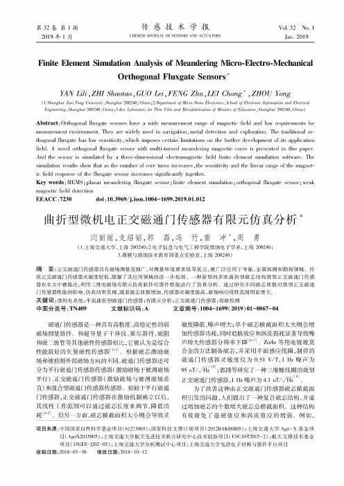
Human
I
Personal computing
Device
Self-propelled Dewce
FIG. 2
Patent Application Publication
-_+
,/ 9
410
412
FIG. 4
Patent Application Publication
Nov. 27, 2014 Sheet 5 0f 5
US 2014/0345957 A1
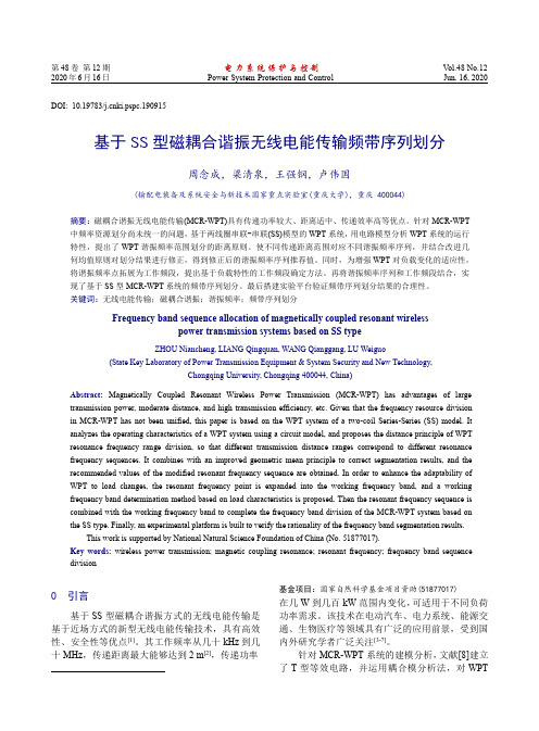
Processor
.549.
Mam Memory
5;.
instructions 5’”
ROM
25;
Storage Device
ESTABLISHING 2-WAY COMMUNICATION FOR CON
net) to produce the magnetic ?eld causing the magnetic inter
action. Such interaction may involve a magnetic attraction in
.
.
g
.
p
.
Pat NO' 8 571 781'
’ ’
the internal drive system and mcludes a sprmg and a sprmg
end 1n contact W1th the mner surface of the spherlcal housmg.
(60)
Provisional application No. 61/430,023, ?led on Jan.
sory, or both can include a magnet (e. g., a neodymium mag
2011; (ii) US. Provisional Patent Application Ser. No.
61/430,083, entitled “METHOD AND SYSTEM FOR
Link
FIG. 5
US 2014/0345957 A1
Nov. 27, 2014
MAGNETICALLY COUPLED ACCESSORY FORA SELF-PROPELLED DEVICE RELATED APPLICATIONS
motors, and the force of the biasing mechanism against the inner surface. A magnetic coupling component may be included with the biasing mechanism. The magnetic coupling
Ser. No. 61/430,023, entitled “METHOD AND SYSTEM FOR CONTROLLING A ROBOTIC DEVICE,” ?led Jan. 5,
tion through the spherical housing.
[0011] Either the self-propelled device, the external acces
PELLED DEVICE WITH ACTIVELY ENGAGED DRIVE
through the spherical housing to magnetically interact with
external devices or accessories.
SYSTEM,” ?led Sep. 24, 2013; which is a Continuation of US. patent application Ser. No. 13/342,853, entitled “SELF
entitled “A SELF-PROPELLED DEVICE AND SYSTEM AND METHOD FOR CONTROLLING SAME,” ?led Oct.
outer surface of the spherical housing. In such examples, friction may be reduced by coating the outer surface of the
US 20140345957A1
(19) United States (12) Patent Application Publication (10) Pub. No.: US 2014/0345957 A1
Bernstein et al.
(54) MAGNETICALLY COUPLED ACCESSORY
31, 2011; all of the aforementioned priority applications
being hereby incorporated by reference in their respective
entirety.
BACKGROUND
repulsive force including stability mechanism (e.g., one or
Nov. 27, 2014 Sheet 3 0f 5
US 2014/0345957 A1