LTE-Advanced
LTE-Advanced(4G)主要技术学习:CA、CoMp、HetNet
LTE-Advanced(4G)主要技术学习:CA、CoMp、HetNet CA:Carrier Aggregation,载波聚合从LTE到LTE-Advanced演进过程中,更宽频谱的需求是影响演进的最重要因素,为此3GPP标准提出了载波聚合技术。
简单地说,它可以将多个载波聚合成⼀个更宽的频谱,同时也可以把⼀些不连续的频谱碎⽚聚合到⼀起,能很好地满⾜LTE、LTE-Advanced系统频谱兼容性的要求,不仅能加速标准化进程,还能最⼤限度地利⽤现有LTE设备和频谱资源。
得益于更宽的频谱,载波聚合后最直观的好处就是传输速度的⼤幅度提升,以及延迟的降低。
同时,载波聚合还能有效改善⽹络质量,提升吞吐量,使⽹络负载更加均衡,尤其是在负载较重的时候效果会更明显。
打个⽐⽅,载波聚合就好⽐“黏合剂”,将零散的频谱粘在⼀起,提供更快速率。
CoMp:Coordinated Multiple Points,协作多点传输技术是指协调的多点发射/接收技术,这⾥的多点是指地理上分离的多个天线接⼊点。
CoMP技术的实质是在不同基站之间通过协同处理⼲扰、或者避免⼲扰、或者将⼲扰转化为有⽤信号,为⽤户提供更⾼速率,从⽽提⾼⽹络的利⽤率。
本质上,CoMP技术是MIMO技术在多⼩区下的应⽤,利⽤空间信道上的差异来进⾏信号传输。
CoMP技术引⼊的主要⽬的是提升⽹络性能特别是对于⼩区边缘⽤户的速率。
针对于下⾏链路需要通过CoMP动态协调eNode-B之间对某UE数据传输,实现⽤户速率提升。
虽然LTE CoMP技术是⼀个复杂技术,但是它给LTE⽹络带来很多的好处: 提升⽆线资源利⽤率:终端同时由多个基站服务,通过CoMP可以选择最好⼩区为终端提供服务,实现最⼩资源最⼤速率体验,从⽽有效提升⽆线资源利⽤率; 改善⼩区间切换性能:由于UE同时与多个⼩区保持连接状态,这意味着⼩区的总体接收能⼒的提升并将极⼤地减少掉话情况的发⽣; 多基站接收提升接收功率:CoMP使得每个UE与多个基站或⼩区相连,通过处理使得UE接收电平得到提升; ⼲扰消除:使⽤专门合并技术可以有效利⽤有⽤⼲扰⽽不是⽆⽤⼲扰,从⽽降低⼩区间的⼲扰CoMP具有提升整体频谱利⽤率、改善⼩区间切换性能、提升UE接收功率和⼲扰消除等优点,同时由于其对时频同步要求较⾼导致要求较⾼的⽹络配置要求(BBU集中放置并使⽤GPS同步)。
LTE-Advanced系统中继技术综述
o ot dT lcmmu iain, og ig4 0 6 ) f s a eeo P sn nct s nqn 00 5 o Ch
摘 要: 中继 技术 是 L E A vne T — dacd的关键 技术 之一 , 增大 系统 覆盖 , 高链路 性 能。本 文总结 了近十年 来 国 内 能 提
外 中继 技 术研 究 的发 展过 程 . 细 综述 L E A vn e 系统 中 继技 术 的研 究现 状 , 详 T — dac d 主要 针 对 L E A中引 入 中继 T—
后 的数据 传输 方案 及 中继技术 对 该系统 的影 响 。最后 , 对进一 步需 要研 究的 问题进 行 了讨论 。
,
pe f m a c Su m e p e e eopmen ft e h olgyho e a d br d o e h s c e. t l v r i r or n e m du t h dvl t o he r ly t ec n o m n a oa v rt e pa t de ad a deai ed o e vew f u - o r c r nt t t s o e e r n r l y b s T A d a e y t m s pr s n e m ail o h at r ns s in s e e o T A tr e a u fr s a ch i e a a ed on L E— s v nc d S s e i e e t d ny f rt e d a ta mi so ch m fL E— af e
1引言
随着移动通 信业的迅速发 展 ,未来移 动通 信系统需要更 高的速率 , 更广 泛的信号覆盖及更大 的移动性 。 T — d acd L E A vne 系统 提 出下行 峰值 速 率超 过 1 bt Gi /S和上行 峰 值速 率 超过 50 i 0 Mbt /S的性能要求 。在相 同的发送功 率条 件下 , 符号能量 会随着传输速率 的增加而线性 减少 ,为 了保 证较高 的数据传 输速率 , 只能 降低小 区的覆盖范 围 。L E A vn e T — da cd的潜在部 署频段包括 3 . .G z44~ .9 Hz ,工作 在更高 的频 4~42 H ,. 49 G 等
LTE实战技巧之速率提升
LTE实战技巧之速率提升在LTE网络中,速率提升是提高用户体验和满足用户需求的关键。
以下是一些LTE实战技巧,可用于提高网络速率。
1.频谱优化:频谱是LTE网络传输数据的基础,优化频谱的使用可以大幅提升网络速率。
其中一种常用的优化方法是频谱分配,即将可用频段分配给不同的用户和服务,以最大程度地提高网络容量和速率。
2.增加小区密度:在LTE网络中,小区是网络传输的基本单元。
增加小区密度可以提供更好的信号覆盖和更高的网络容量,从而提高速率。
这可以通过增加基站的数量或扩展现有基站的覆盖范围来实现。
3.使用MIMO技术:MIMO(多输入多输出)技术可以利用多个天线在同一时间和频段传输和接收多个数据流,从而提高网络速率。
通过增加天线数量,可以提高信号强度和抗干扰能力,从而提高网络速率。
4.使用高级调制方式:LTE网络支持多种调制方式,包括16QAM和64QAM。
这些高级调制方式可以在相同的频谱资源和时间间隙中传输更多的数据,提高网络速率。
但是,高级调制方式对信号质量要求更高,因此需要更好的信号覆盖和抗干扰能力。
5.优化信道资源分配:LTE网络的信道资源是有限的,因此需要合理地分配给各个用户和服务。
通过合理的信道资源分配可以避免资源浪费和冲突,提高网络速率。
例如,可以通过动态资源分配和调度算法来根据用户需求和网络负载实时分配信道资源。
6.使用小区间协同:在密集城区等高容量和高速率要求的地区,可以使用小区间协同技术。
小区间协同可以将相邻基站的信号和资源协同使用,提高网络容量和速率。
例如,可以通过信号干扰协调和资源共享来提高网络速率。
7.使用载波聚合技术:LTE网络支持多载波聚合(CA)技术,可以同时利用多个载波进行数据传输,提高网络速率。
通过将不同频段的载波组合在一起,可以提供更大的带宽和更高的速率。
但是,载波聚合要求设备和网络支持,因此需要相应的设备和网络配置。
8.优化调度算法:调度算法是决定哪个用户在何时使用网络资源的关键。
第四代移动通信技术标准

第四代移动通信技术标准
第四代移动通信技术标准被称为LTE(Long Term Evolution),它是一种高速无线数据传输技术,旨在提供更高的数据传输速度和更低的延迟。
LTE标准的开发是为了满足不断增长的移动数据需求和更高的用户体验要求。
LTE的主要特点包括:
1. 高速数据传输:LTE可以提供非常高的数据传输速度,支持下行速度高达100 Mbps以上和上行速度高达50 Mbps以上,这使得用户可以更快地下载和上传数据,实现高清视频流媒体、在线游戏和其他高带宽应用。
2. 较低的延迟:LTE的延迟较低,通常在几十毫秒范围内。
这对于实时应用,如互动游戏、视频通话和远程控制等非常重要,能够提供更好的用户体验。
3. 高效的频谱利用:LTE采用了OFDMA(正交频分多址)和MIMO(多输入多输出)技术,能够更有效地利用可用的频谱资源,提供更大的容量和更好的网络性能。
4. 平滑升级路径:LTE是向下兼容的,可以与现有的2G和3G网络进行平滑过渡,同时也为未来的技术演进提供了良好的基础。
LTE的进一步发展演变为LTE-Advanced(LTE-A)和LTE-Advanced Pro(LTE-A Pro)等更高级别的技术标准。
LTE已经成为全球范围内主流的移动通信技术,许多运营商和设备制造商都采用了LTE标准,为用户提供更快速、可靠的无线通信服务。
TP-Link LTE-Advanced Mobile Wi-Fi M7650 说明书
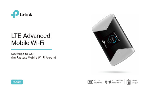
LTE-Advanced Mobile Wi-FiM7650600Mbps to Go:the Fastest Mobile Wi-Fi Around4G LTE 600Mbps AC1200 Dual Band Wi-Fi 15hrs UsageThe M7650 features a compact, elegant design very suitable for travel, business trips, outdoor activities or wherever you may be. Share LTE-Advanced Connection on the GoThe1.44 inch TFT intuitive screen display of M7650 makes it easy to stay within your data budget and helps avoid going over the monthly data cap. The screen also displays other much more information of battery life, signal strength, Wi-Fi status, connected users and more.All Useful Info at a Color ScreenBattery LifeData RoamingDownload SpeedData Usage560MBConnected DevicesMessageSignal StrengthNetwork Type4G/3G/2G50M/S* Parameters above are only for demonstration.With the tpMiFi App, you can easily access and manage the M7650 from your connected iOS/Android devices. The tpMiFi app allows you to establish data limits, control which devices can access your Wi-Fi, send messages, and sharemedia files to/from a removable Micro SD card.Easy Management with the tpMiFi App· The latest generation 4G LTE Advanced – Supports 4G LTE Advanced network, compatible with 3G/2G network· The Faster Connections – reaches up to 600Mbps download speed and 50Mbps upload one, to enjoy HD movies without interruption, download files in seconds, and hold a video chat without dropouts.· Dual Band Wi-Fi – Selectable 2.4GHz or 5GHz dual band Wi-Fi, achieves better network connectivity when you are in network interference.· High-Speed Hotspots – Shares 2.4GHz 300Mbps or 5GHz 867Mbps Wi-Fi with up to 32 Wi-Fi devices.Lightning 4G LTE AdvancedDual Band Wi-Fi15 Hours Usage· 3000mAh – 3000mAh battery capacity · 15 hours – 15 hours of 4G sharing · 720 hours – 720 hours of standby* Actual battery time may vary due to different using environments· One-Key Setup – To create a hotspot, just insert a SIM card and press the power button.· 32 devices – Supports up to 32 devices simultaneously to share 4G/3G/2G network· Compact design – Suitable for travel, business trips, outdoor activities or wherever you may be · Storage Sharing – Easily share photos, music, videos and more wirelessly across your network· Up to 32GB – Equipped with a micro SD card slot for up to 32GB of optional storageEasy Using Storage Wireless SharingHardware· Interface : 1 micro USB port for power supply, 1 micro SIM card slot, 1 micro SD card slot· Button: Power On/Off Button, Menu Button, Reset Button· Screen Display: Traffic statistics, Wi-Fi status, user numbers, network type (2G/3G/4G), signal strength, Internet connection status, messages, battery life, Wi-Fi name, Wi-Fi password.· External Power Supply: 5V/1A· Dimensions (W x D x H): 4.2 × 2.6 × 0.6 in. (106 × 66 × 16mm) · Antenna: Internal Antennas Wireless· Network Type:4G: FDD-LTE B1/B3/B7/B8/B20 (2100/1800/2600/900/800MHz) 3G: DC-HSPA+/HSPA/UMTS B1/B8 (2100/900MHz)2G: EDGE/GPRS/GSM (850/900/1800/1900MHz)· Wireless Standards: IEEE 802.11n/a/ac 5GHz, IEEE 802.11b/g/n 2.4GHz· Frequency: 5GHz and 2.4GHz· Signal Rate: Selectable dual band, 300Mbps at 2.4GHz or 867Mbps at 5GHz· Transmit Power: <20dBm· Reception Sensitivity:5GHz: 11a 54Mbps: -70dBm;11n HT20 MCS7: -68dBm;11n HT40 MCS7: -65dBm.2.4GHz: 11b 11Mbps: -86dBm;11g 54Mbps: -71dBm;11n HT20 MCS7: -68dBm;11n HT40 MCS7: -65dBm;· Wireless Security: Support WPA-PSK/WPA2-PSK,Wireless MAC Filtering, Enable/Disable SSID Broadcast· DHCP: Server, Client, DHCP Client ListOthers· Certification: CE, RoHS· System Requirements:Windows 10/8/7/vista/XP, Mac OS, Android, iOS, Windows Phone· EnvironmentOperating Temperature: 0℃~35℃ (32℉ ~95℉)Storage Temperature: -20℃~60℃ (4℉ ~140℉)Operating Humidity: 10%~90% non-condensingStorage Humidity: 5%~90% non-condensing· Package ContentsLTE-Advanced Mobile Wi-Fi M7650Micro USB CableNano to Micro SIM Card AdapterQuick Installation Guide3000mAh BatteryFor more information, please visit/en/products/details/M7650.html。
什么是LTE-A
什么是LTE-ALTE-A是LTE-Advanced的简称,是LTE技术的后续演进。
LTE俗称3.9G,这说明LTE的技术指标已经与4G非常接近了。
LTE与4G相比较,除最大带宽、上行峰值速率两个指标略低于4G要求外,其他技术指标都已经达到了4G标准的要求。
而将LTE正式带入4G的LTE-A的技术整体设计则远超过了4G的最小需求。
在2008年6月,3GPP完成了LTE-A的技术需求报告,提出了LTE-A的最小需求:下行峰值速率1Gbps,上行峰值速率500Mbps,上下行峰值频谱利用率分别达到15Mbps/Hz和30Mbps/Hz。
这些参数已经远高于ITU的最小技术需求指标,具有明显的优势。
LTE-A主要技术特征为了满足IMT-Advanced(4G)的各种需求指标,3GPP针对LTE-Advanced(LTE- A)提出了几个关键技术,包括载波聚合、协作多点发送和接收、接力传输、多天线增强等。
LTE-A系统的关键技术包括:载波聚合LTE-A支持连续载波聚合以及频带内和频带间的非连续载波聚合,最大能聚合带宽可达100MHz。
为了在LTE-A商用初期能有效利用载波,即保证LTE终端能够接入LTE-A系统,每个载波应能够配置成与LTE后向兼容的载波,然而也不排除设计仅被LTE-A系统使用的载波。
目前3GPP根据运营商的需求识别出了12种载波聚合的应用场景,其中4种作为近期重点分别涉及到FDD和TDD的连续和非连续载波聚合场景。
在LTE- A的研究阶段,载波聚合的相关研究重点包括连续载波聚合的频谱利用率提升,上下行非对称的载波聚合场景的控制信道的设计等。
多点协作多点协作分为多点协调调度和多点联合处理两大类,分别适用于不同的应用场景,互相之间不能完全取代。
多点协调调度的研究主要是集中在和多天线波束赋形相结合的解决方案上。
在3GPP最近针对ITU的初步评估中,多点协作技术是唯一能在基站四天线配置条件下满足所有场景的需求指标的技术,并同时明显改进上行和下行的系统性能,因此多点协调的标准化进度成为3GPP提交的4G候选方案和面向ITU评估的重中之重。
3gpp lte标准
3gpp lte标准3GPP LTE标准。
LTE(Long Term Evolution)是第四代移动通信技术的一种,它是3GPP(第三代合作伙伴计划)组织制定的全球通用的移动通信标准。
LTE标准的制定是为了满足用户对移动宽带数据业务的需求,提供更高的数据传输速率、更低的时延和更好的移动性能。
LTE标准的制定经历了多个版本的演进,其中包括LTE Release 8、LTE-Advanced和LTE-Advanced Pro等。
LTE标准的主要特点包括以下几个方面:1. 高速数据传输,LTE标准采用了多天线技术、OFDMA(正交频分多址)和MIMO(多输入多输出)等技术,可以实现更高的数据传输速率。
在LTE-Advanced Pro版本中,还引入了更高阶的调制技术和更宽的频谱,进一步提高了数据传输速率。
2. 低时延,LTE标准采用了更高的调制方式和更短的传输时隙,可以实现更低的时延。
这对于实时语音通话、在线游戏等对时延要求较高的业务非常重要。
3. 高移动性能,LTE标准采用了更好的切换机制和更优化的无线资源分配算法,可以实现更好的移动性能。
用户在高速移动时也可以获得稳定的数据传输体验。
LTE标准的演进主要体现在以下几个方面:1. LTE Release 8,LTE Release 8是LTE标准的最初版本,它主要实现了基本的LTE网络架构和无线接入技术。
在LTE Release 8中,LTE网络可以提供100Mbps的下行速率和50Mbps的上行速率。
2. LTE-Advanced,LTE-Advanced是LTE标准的演进版本,它在LTE Release 8的基础上引入了更多的技术创新,包括更高阶的调制技术、更宽的频谱和更好的干扰协调技术等。
在LTE-Advanced网络中,可以实现更高的数据传输速率和更好的网络性能。
3. LTE-Advanced Pro,LTE-Advanced Pro是LTE标准的进一步演进版本,它在LTE-Advanced的基础上引入了更多的技术创新,包括更高阶的MIMO技术、更宽的频谱和更高的调制方式等。
LTE和LTE-Advanced关键技术综述

下面将逐一介绍LTE中使用的关键技术和
LTE—Advanced中考虑采用的关键技术。
模式是对单个子帧操作;两种模式所支持的HARQ
流程数也是不一样的,普通模式对应的流程数为8, 子帧捆绑模式的流程数为4。终端根据eNB在下行
2
2.1
LTE的关键技术
能更有效地利用系统资源。在R8 LTE中,上行支持 64QAM对终端和eNB均为可选。
2.3 HARQ
工作,目标是成为IMT—Advanced的候选技术。通过 引入多载波聚合、上下行MIMO扩展、中继、分布式 天线等关键技术进行平滑演进,进一步发挥技术优 势提升网络性能,提高用户对移动通信业务的体验,
0FDM和SC-FDMA
PDCCH上的新数据指示(NDI)比特或物理HARQ
指示信道(PHICH)来判断是否需要重传,如果需要 重传,终端将会在固定数目子帧后重传。
2.4先进的多天线技术 LTE在下行采用OFDM,上行采用单载波一频分
多址(SC—FDMA)。OFDM使得同一小区中用户信号
之间可以保持正交性,SC—FDMA可以看成是对用户
使用OFDMA,因它调度更灵活,也可以简化演进的基
站(eNB)侧均衡器和上行使用MIMO时的实现。
2.2更高阶调制(64QAM) LTE中上、下行均可自适应使用正交相移键控
R8在上行只使用SDMA和多天线接收分集技术,未 来应该也会考虑MIMO技术。LTE标准目前最高支
凸、.-...M..S.T..T....S.e.ptember
LTE在下行灵活使用MIM0、空分多址(SD MA)、波束成型和接收/发送分集等多天线技术:对 信干比高和空间信道散列度高(信道矩阵值高和奇 异值高)的用户使用MIMO技术,以提供更高的数 据速率;当需要为更多用户服务时,利用SDMA技术 在同一时、频资源上为多个用户同时提供服务;对某 些用户使用波束成型技术,将发送/接收波束对准 用户,以提高用户的数据速率;当不需要使用 SDMA,MIMO也无法带来附加增益时,使用传统的
- 1、下载文档前请自行甄别文档内容的完整性,平台不提供额外的编辑、内容补充、找答案等附加服务。
- 2、"仅部分预览"的文档,不可在线预览部分如存在完整性等问题,可反馈申请退款(可完整预览的文档不适用该条件!)。
- 3、如文档侵犯您的权益,请联系客服反馈,我们会尽快为您处理(人工客服工作时间:9:00-18:30)。
LTE-AdvancedHome Technologies Keywords & Acronyms LTE-AdvancedAuthor: Jeanette Wannstrom, for 3GPP,(Submission, June 2013)In LTE-Advanced focus is on higher capacity:The driving force to further develop LTE towards LTE–Advanced - LTE Release10 was to provide higher bitrates in a cost efficient way and, at the same time, completely fulfil the requirements set by ITU for IMT Advanced, also referred to as 4G.Increased peak data rate, DL 3 Gbps, UL 1.5 GbpsHigher spectral efficiency, from a maximum of 16bps/Hz in R8 to 30 bps/Hz in R10Increased number of simultaneously active subscribersImproved performance at cell edges, e.g. for DL 2x2 MIMO at least 2.40 bps/Hz/cell.The main new functionalities introduced in LTE-Advanced are Carrier Aggregation (CA), enhanced use of multi-antenna techniques and support for Relay Nodes (RN).Carrier AggregationThe most straightforward way to increase capacity is to add more bandwidth. Since it is important to keep backward compatibility with R8 and R9 mobiles the increase in bandwidth in LTE-Advanced is provided through aggregation of R8/R9 carriers. Carrier aggregation can be used for both FDD and TDD.Each aggregated carrier is referred to as a component carrier. The component carrier can have a bandwidth of 1.4, 3, 5, 10, 15 or 20 MHz and a maximum of five component carriers can be aggregated. Hence the maximum bandwidth is 100 MHz. The number of aggregated carriers can be different in DL and UL, however the number of UL component carriers is never larger than the number of DL component carriers. The individual component carriers can also be of different bandwidths, see figure 1.Figure 1. Carrier Aggregation – FDDThe R10 UE can be allocated resources DL and UL on up to five Component Carriers (CC). The R8/R9 UEs can be allocated resources on any ONE of the CCs. The CCs can be of different bandwidths.For practical reasons different carrier aggregation configurations – specified by e.g. combinations of E-UTRA operating band and the number of component carriers - are introduced in steps. In R10 there are two component carriers in the DL and only one in the UL (hence no carrier aggregation in the UL), in R11 there are two component carriers DL and one or two component carriers in the UL when carrier aggregation is used.The easiest way to arrange aggregation is to use contiguous component carriers within the same operating frequency band (as defined for LTE), so called intra-band contiguous. This might not always be possible, due to frequency allocation scenarios. For non-contiguous allocation it could either be intra-band, i.e. the component carriers belong to the same operating frequency band, but are separated by a frequency gap, or it could be inter-band, in which case the component carriers belong to different operating frequency bands, see figure 2.Figure 2 Carrier Aggregation – Intra- and inter-band alternatives.When carrier aggregation is used there is a number of serving cells, one for each component carrier. The coverage of the serving cells may differ – due to e.g. component carrier frequencies. The RRC connection is handled by one cell, the Primary serving cell, served by the Primary component carrier (DL and UL PCC). The other component carriers are all referred to as Secondary component carrier (DL and possibly UL SCC), serving the Secondary serving cells.In the inter-band CA example shown in figure 3, carrier aggregation on all three component carriers is only possible for the black UE, the white UE is not within the coverage area of the red component carrier.Figure 3. Carrier Aggregation; Serving CellsEach Component Carrier corresponds to a serving cell. The different serving cella may have different coverage.Introduction of carrier aggregation influences mainly MAC and the physical layer protocol, but also the RLC buffer must be larger and RRC must be able to make decisions about addition/removal of secondary CC.MIMO, Multiple Input Multiple Output – or spatial multiplexingMIMO is used to increase the overall bitrate through transmission of two (or more) different data streams on two (or more) different antennas - using the same resources in both frequency and time, separated only through use of different reference signals - to be received by two or more antennas, see figure 4.Figure 4. Simplified illustration of 2x2 MIMO (Spatial Multiplexing). Two different data streams are transmitted on two TX antennas and received by two RX antennas, using the same frequency and time, separated only by the use of different reference signals.One or two transport blocks are transmitted per TTI. A major change in LTE-Advanced is the introduction of 8x8 MIMO in the DL and 4x4 in the UL.MIMO can be used when S/N (Signal to Noise ratio) is high, i.e. high quality radio channel. For situations with low S/N it is better to use other types of multi-antenna techniques to instead improve the S/N, e.g. by means of TX-diversity, see figure 5.Figure 5. MIMO is recommended for high S/N and TX diversity is preferably used for low S/N scenarios.To be able to adjust the type of multi-antenna transmission scheme, according to e.g. radio environment, a number of different Transmission Modes (TM) has been defined. The UE will through RRC signalling be informed about the transmission mode to use. In the DL there are nine different transmission modes, where TM1-7 were introduced in R8, TM8 was introduced in R9 and TM9 was introduced in R10. In the UL there are TM1 and TM2, where TM1, the default, wasintroduced in R8 and TM2 was introduced in R10. The different transmission modes differ in;Number of layers (streams, or rank)Antenna ports usedType of reference signal, Cell-specific Reference Signal (CRS) or Demodulation Reference Signal (DM-RS),introduced in R10.Precoding typeThrough the introduction of TM9 8x8 MIMO is supported DL, and through the introduction of TM2 UL use of 4x4 MIMO UL is enabled. Naturally it is also required that the UE support this. In R10 three new UE categories are introduced, category 6, 7 and 8 – where UE category 8 supports the maximum number of CC and 8x8 spatial multiplexing.In multi-antenna techniques precoding is used to map the modulation symbols onto the different antennas. The type of precoding depends on the multi-antenna technique used as well as on the number of layers and the number of antenna ports. The aim with precoding is to achieve the best possible data reception at the receiver.Note that the signal will be influenced by fading of various types, which can also be seen as some type of coding caused by the radio channel.To handle this, known reference signals will be transmitted together with the data, and used by the receiver for demodulation of the received signal.In R8 the reference signal is added to the signal after precoding, one CRS (Cell-specific Reference Signal) per antenna. From the received CRS the UE estimates how the radio channel influenced the signal. Using this together with knowledge about the used code-book based precoding, the UE can demodulate the received signal and regenerate the information sent.In R10 the DM-RSs (Demodulation Reference Signals) are added to the different data streams before precoding. Knowledge about the reference signal will provide information about the combined influence of radio channel and precoding, no pre-knowledge about the precoder is required by the receiver, this case is referred to as non-codebook based precoding, see figure 6.Figure 6. MIMO DL with precoding and reference signal for demodulation in R8 and R10. CRS is a cell specific reference signal, DM-RS is a UE specific reference signal, also specific per data stream.Relay NodesIn LTE-Advanced, the possibility for efficient heterogeneous network planning – i.e. a mix of large and small cells - is increased by introduction of Relay Nodes (RNs). The Relay Nodes are low power base stations that will provide enhanced coverage and capacity at cell edges, and hot-spot areas and it can also be used to connect to remote areas without fibre connection. The Relay Node is connected to the Donor eNB (DeNB) via a radio interface, Un, which is a modification of the E-UTRAN air interface Uu. Hence in the Donor cell the radio resources are shared between UEs served directly by the DeNB and the Relay Nodes. When the Uu and Un use different frequencies the Relay Node is referred to as a Type 1a RN, for Type 1 RN Uu and Un utilize the same frequencies, see figure 7. In the latter case there is a high risk for self interference in the Relay Node, when receiving on Uu and transmitting on Un at the same time (or vice versa). This can be avoided through time sharing between Uu and Un, or having different locations of the transmitter and receiver. The RN will to a large extent support the same functionalities as the eNB – however the DeNB will be responsible for MME selection.Figure 7. The Relay Node (RN) is connected to the DeNB via the radio interface Un. UEs at the edge of the donor cell are connected to the RN via Uu, while UEs closer to the DeNB are directly connected to the DeNB via the Uu interface. The frequencies used on Un and Uu can be different, outband, or the same, inband. In the inband case there is a risk for self interference in the RN.Coordinated Multi Point operation (CoMP) – R11LTE-Advanced continues to evolve. New CA configurations are added (additions of new bands for CA are not bound to specific releases) and there are new features introduced in coming releases of the 3GPP specifications, such as Coordinated Multi Point (CoMP) introduced in R11.The main reason to introduce CoMP is to improve network performance at cell edges. In CoMP a number of TX (transmit) points provide coordinated transmission in the DL, and a number of RX (receive) points provide coordinated reception in the UL. A TX/RX-point constitutes of a set of co-located TX/RX antennas providing coverage in the same sector. The set of TX/RX-points used in CoMP can either be at different locations, or co-sited but providing coverage in different sectors, they can also belong to the same or different eNBs. CoMP can be done in a number of ways, and the coordination can be done for both homogenous networks as well as heterogeneous networks. In figure 8 two simplified examples for DL CoMP is shown. In both these cases DL data is available for transmission from two TX-points. When two, or more, TX-points, transmit on the same frequency in the same subframe it is called Joint Transmission. When data is available for transmission at two or more TX-points but only scheduled from one TX-point in each subframe it is called Dynamic Point Selection. For UL CoMP there is for example Joint Reception, a number of RX-points receive the UL data from one UE, and the received data is combined to improve the quality. When the TX/RX-points are controlled by different eNBs extra delay might be added, since the eNBs must communicate, for example in order to make scheduling decisions. When CoMP is used additional radio resources for signaling is required e.g. to provide UE scheduling information for the different DL/UL resources.Figure 8. DL CoMP a) Joint Transmission; two TX-points transmit to one UE in the same radio resource,b) Dynamic Point Selection; two TX points are ready to transmit, but only one will be scheduled in each subframe.Further readingTR 36.806 Evolved Universal Terrestrial Radio Access (E-UTRA); Relay architectures for E-UTRA (LTE-Advanced)TR 36.808 Evolved Universal Terrestrial Radio Access (E-UTRA); Carrier Aggregation; Base Station (BS) radiotransmission and receptionTR 36.814 Evolved Universal Terrestrial Radio Access (E-UTRA); Further advancements for E-UTRA physical layer aspectsTR 36.815 Further Advancements for E-UTRA; LTE-Advanced feasibility studies in RAN WG4TR 36.817 Evolved Universal Terrestrial Radio Access (E-UTRA); Uplink multiple antenna transmission; Base Station (BS) radio transmission and receptionTR 36.819 Coordinated multi-point operation for LTE physical layer aspectsTR 36.823 Evolved Universal Terrestrial Radio Access (E-UTRA); Carrier Aggregation Enhancements; UE and BS radio transmission and receptionTR 36.826 Evolved Universal Terrestrial Radio Access (E-UTRA); Relay radio transmission and receptionTR 36.871 Evolved Universal Terrestrial Radio Access (E-UTRA); Downlink Multiple Input Multiple Output (MIMO) enhancement for LTE-AdvancedTR 36.912 Feasibility study for Further Advancements for E-UTRA (LTE-Advanced)TR 36.913 Requirements for further advancements for Evolved Universal Terrestrial Radio Access (E-UTRA) (LTE-Advanced)TS 36.101 Evolved Universal Terrestrial Radio Access (E-UTRA); User Equipment (UE) radio transmission and receptionTS 36.211 Evolved Universal Terrestrial Radio Access (E-UTRA); Physical channels and modulationTS 36.212 Evolved Universal Terrestrial Radio Access (E-UTRA); Multiplexing and channel codingTS 36.213 Evolved Universal Terrestrial Radio Access (E-UTRA); Physical layer proceduresTS 36.216 Evolved Universal Terrestrial Radio Access (E-UTRA); Physical layer for relaying operationTS 36.221 Evolved Universal Terrestrial Radio Access (E-UTRA); Medium Access Control (MAC) protocol specificationTS 36.300 Evolved Universal Terrestrial Radio Access (E-UTRA) and Evolved Universal Terrestrial Radio Access Network (E-UTRAN); Overall description; Stage 2TS 36.306 Evolved Universal Terrestrial Radio Access (E-UTRA); User Equipment (UE) radio access capabilitiesTS 36.331 Evolved Universal Terrestrial Radio Access (E-UTRA); Radio resource Control (RRC) protocol specification。