MY1B25G-2000H资料下载
电器维修设备标书
本文由月月0615贡献doc文档可能在WAP端浏览体验不佳。
建议您优先选择TXT,或下载源文件到本机查看。
本资料未经签章确认无效TSZFCG2010G10794 政府采购批号:TSZFCG2010G10794 TSZFCG2010G 编号:编号:94政府项目名称:政府项目名称:教学设备采购人:唐山市轻工技术学校唐山市轻工技术学校唐山市政府采购货物招标文件唐山市政府采购中心(签章)唐山市政府采购中心(签章)二〇一〇年十一月1文件目录一、投标邀请函二、技术规范要求三、投标人须知四、合同主要条款五、附件2声明为了保证政府采购活动的公正、公平、客观,为了保证政府采购活动的公正、公平、客观,我中心在此郑重声明:本文件及有关附件作为招标我中心在此郑重声明:依据,对投标方及参与人均具有约束力,依据,对投标方及参与人均具有约束力,投标方编制投标文件必须按照本文件的约定进行, 制投标文件必须按照本文件的约定进行,由于对招的约定进行标文件的误解而造成的被取消授予合同的资格或其他情况,后果自负。
其他情况,后果自负。
唐山市政府采购中心2010. 2010.11 103第一部分投标邀请函唐山市政府采购中心受唐山市轻工技术学校的委托,遵循公开透明、公平竞争、公正及诚实信用的原则,对该单位所需教学设备进行公开招标采购。
1、采购批号:TSZFCG2010G10794 2、项目名称:教学设备3、评标办法:最低评标价法4、项目完成期限:合同签订后30 天5、项目实施地点:唐山市轻工技术学校6、投标人资格:具有独立承担民事责任且经营范围中包含此项目内容的供应商7、领取招标文件时间:2010 年12 月 2 日-10 日上午9:00-11:00(节假日除外) 8、领取招标文件时必须提供以下真实的资质原件及一套以下资料的复印件加盖公章备案:1)营业执照副本原件身份证和授权委托书原件(法定代表人领取标书的不需要授权委托书2)身份证和授权委托书原件(法定代表人领取标书的不需要授权委托书)委托投标人提供的资料如果是外文应附有相应的有效中文译本,外文资料与中文译本不一致之处,以中文译本为准。
G1MMH中文资料

S u b j e c t t o m o d i fi c a t i o n i n t e c h n i c a n d d e s i g n . E r r o r s a n d o m i s s i o n s e x c e p t e d .008G1MMH with modular bus cover FeaturesEncoder multiturn / bus cover –Optical sensing–Resolution: singleturn 13 bit, multiturn 16 bit –Hollow shaft of 1” and 2” diameter–High flexibility in mounting and maintenance –Resolution, baud rate, node ID optionally selectable –Code continuity check optional by bus –Technical data - electrical ratings Voltage supply 10...30 VDC Reverse polarity protection YesConsumption w/o load ≤100 mA (24 VDC)Initializing time (typ.)250 ms after power on Interfaces Profibus-DPV0, CANopen, DeviceNet Function MultiturnUser address Rotary switch in bus cover Steps per turn 8192 / 13 bit Number of turns 65536 / 16 bit Absolute accuracy ±0.025°Sensing method Optical CodeBinaryCode sequence CW/CCW programmable Interference immunity DIN EN 61000-6-2Emitted interference DIN EN 61000-6-4Programmable parametersSteps per revolution Number of revolutions Preset ScalingRotational direction Diagnostic functions Position or parameter error Multiturn sensingStatus indicator DUO-LED integrated in bus coverApprovalUL approval / E63076G1MMH, G2MMH - multivoTechnical data - mechanical design Protection DIN EN 60529IP 54MaterialsHousing: aluminium Flange: aluminium Bus cover: aluminium Operating temperature -25...+85 °C-40...+85 °C (optional)Relative humidity 95 % non-condensing ResistanceDIN EN 60068-2-6Vibration 10 g, 16-2000 Hz DIN EN 60068-2-27 Shock 200 g, 6 ms E-connection Bus coverG1MMH Housing ø90 mmShaftø20 mm hollow shaft ø25.4 mm hollow shaft Operating speed ≤3800 rpm (mechanical) ≤6000 rpm (electric)Rotor moment of inertia 2000 gcm²Weight approx.890 gG2MMH Housing ø116 mmShaftø50.8 mm hollow shaft Operating speed ≤2000 rpm (mechanical) ≤6000 rpm (electric)Rotor moment of inertia 11000 gcm²Weight approx.1200 g OptionalModular bus covers for SSI interface–S u b j e c t t o m o d i fi c a t i o n i n t e c h n i c a n d d e s i g n . E r r o r s a n d o m i s s i o n s e x c e p t e d .008G1MMH, G2MMH - multivoPart numberG1MMH.20Interface3P32Profibus-DPV0 / cable gland 5P32CANopen / cable gland 8P22DeviceNet / cable glandHollow shaft2Hollow shaft ø25.4 mm with pin 15 mm3Hollow shaft ø20 mm with pin 15 mm G2MMH.20Interface3P32Profibus-DPV0 / cable gland 5P32CANopen / cable gland 8P22DeviceNet / cable glandHollow shaft2Hollow shaft ø50.8 mm with pin 15 mm3Hollow shaft ø50 mm with pin 15 mmAccessoriesMounting accessories for G1MMH (page %S)Z 119.037Rubber buffer element 18.5 mm long, as torque supportZ 119.039 Set of adjusting angles as torque support Z 119.040Shoulder screw M5 as torque support Z 119.041Torque support by rubber buffer element for encoders with 15 mm pin Z 119.043Spring coupling for GX and G1Z 119.050Spring couplingZ 119.053Spring coupling height 19.1 mm Z 119.070Spring coupling height 29.1 mmZ 119.076Spring coupling for encoders with ø58 mm housingMounting accessories for G2MMH (page %S)Z 119.037Rubber buffer element 18.5 mm long, as torque supportZ 119.039 Set of adjusting angles as torque support Z 119.040Shoulder screw M5 as torque support Z 119.041Torque support by rubber buffer element for encoders with 15 mm pin Z 119.050Spring couplingZ 119.053Spring coupling height 19.1 mm Z 119.070Spring coupling height 29.1 mmZ 119.076Spring coupling for encoders with ø58 mm housingProgramming accessories (page %S)Z 150.022CD with describing files & manualsCD with file descriptions is not included in the delivery. You may order them on CD as accessory free-of-charge under part number Z 150.022.Matching bus covers are listed in the chapter “Accessories”.Hollow shaft max. ø25.4 mm Hollow shaft max. ø50.8 mmS u b je c t t o m o d i fi c a t i o n i n t e c h n i c a n d d e s i g n . E r r o r s a n d o m i ss i o n s e xc e p t ed .008G1MMH, G2MMH - multivoDimensionsG2MMH CANopen, ProfibusG1MMH CANopen, ProfibusS u b j e c t t o m o d i fi c a t i o n i n t e c h n i c a n d d e s i g n . E r r o r s a n d o m i s s i o n s e x c e p t e d .008G1MMH, G2MMH - multivo。
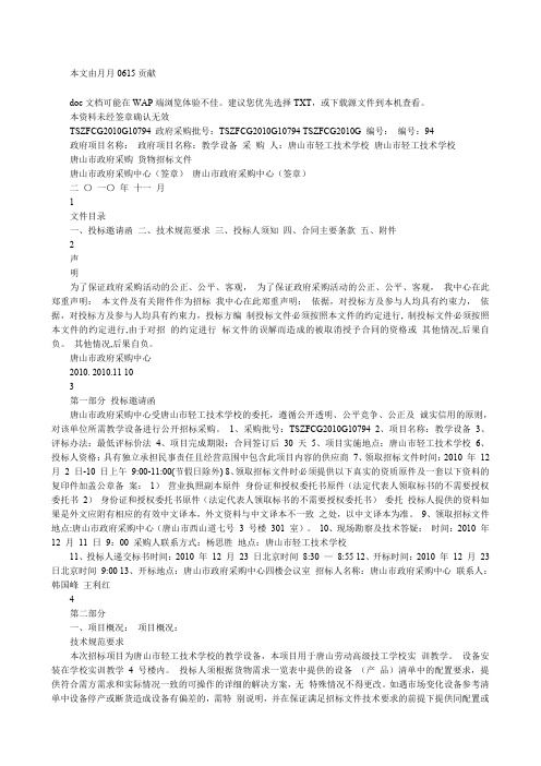
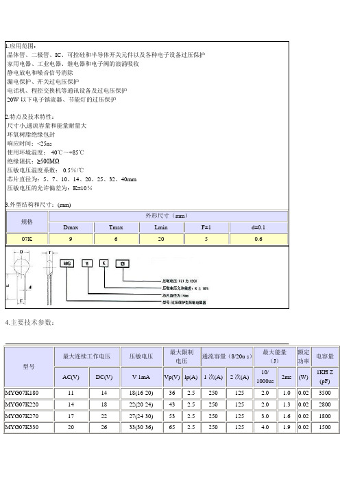
MYG压敏电阻资料
300
360(324-396)
595
10
1200
600
32
23
0.25
140
MYG07K391
250
320
390(351-429)
650
10
1200
600
35
25
0.25
130
MYG07K431
275
350
430(387-473)
710
10
1200
600
40
27.5
0.25
115
MYG07K471
175
225
270(243-297)
455
10
1200
600
24
17
0.25
185
MYG07K301
190
250
300(270-330)
500
10
1200
600
26
18.5
0.25
165
MYG07K331
210
275
330(297-363)
550
10
1200
600
28
20
0.25
150
MYG07K361
36
2.5
250
125
2.0
1.0
0.02
3500
MYG07K220
14
18
22(20-24)
43
2.5
250
125
2.0
1.3
0.02
2800
MYG07K270
17
22
27(24-30)
53
各期气缸统计

涂布定位气缸 擦边气缸 涂布升降气缸 涂布平移气缸 阻挡器 下传送带进\出口气缸 前后升降台气缸
5#生产线气缸统计 气缸型号 MGPM32-25 MDBT63-1100 CDQ2A80-50DZ MDBB63-550 CP96SDB63-120 MDBT63-600 CPQ2A32-10DZ CDG1BN50-580 RSDG50-30DL-C73Z MGPM32-15 CDQ2A32-43DCM CDM2E32-150A MDNBB80-750-D CDQ2A40-50D CDO2A40-50D CP96SDB32-100 品牌 数量 单位 生产线 磁开关型号 SMC SMC SMC SMC SMC SMC SMC SMC SMC SMC SMC SMC SMC SMC SMC SMC 2 2 2 2 1 1 2 12 19 4 4 4 2 8 4 2 5 5 5 5 5 5 5 5 5 5 5 5 5 5 5 5 D-Z73 D-A54 D-A93 D-A54 D-A93 D-A54 D-A93 D-C73 D-C73 D-Z73 D-A73 D-C73 D-Z73 D-A73H D-A73H D-A93 位置 清洗站限流气缸 上\下料平移气缸 上\下料平移升降气缸 上\下料气缸 工件加紧气缸 工件移位气缸 下料升降台加紧气缸 所有门气缸 阻挡器 涂布升降气缸 涂布平移气缸 擦边气缸 前后升降台气缸 涂布定位气缸 前升降台定位气缸 4槽喷淋气缸
MGPM32-15 CDQ2A32-43DCM
涂ቤተ መጻሕፍቲ ባይዱ升降气缸 涂布平移气缸
前升降台气缸 后烘箱门气缸 涂布缸盖平移气缸 涂布缸盖升降气缸
MY1B80G-700-Y59A MDB1B80-610 CP95SDB80-600 MDBB50-570 MDBB100-700 CDG1BN50-580
5082-511G-0H000资料

DescriptionThis 14.22 mm (0.56 inch) LED seven-segment display uses industry standard size package and pinout.The device is available in eithercommon anode or common cathode.Agilent HDSP-511x/513x14.22 mm (0.56 inch) General Purpose Seven-Segment DisplayData SheetFeatures•Industry standard size •Industry standard pinout 14.22 mm (0.56 inch)DIP lead on 2.54 mm •Choice of colorsHigh Efficiency Red (HER), Green,AlGaAs Red, and Yellow •Excellent appearanceEvenly lighted segments gray package gives optimum contrast ± 50° viewing angle •Design flexibilityCommon anode or common cathode Single digitLeft and right hand decimal point•Categorized for luminous intensityGreen and yellow categorized for color Applications•Suitable for indoor use•Not recommended for industrial application, i.e., operating tem-perature requirements exceeding +85˚C or below –25˚C [1]•Extreme temperature cycling not recommendedNotes:1.For additional details, please contact your local Agilent sales office or an authorized distributor.Devices HERGreenAlGaAs Red Yellow DescriptionHDSP-511E HDSP-511G HDSP-511A HDSP-511Y Common Anode, Right Hand Decimal HDSP-513EHDSP-513GHDSP-513AHDSP-513YCommon Cathode, Right Hand DecimalThe choice of colors includes High Efficiency Red (HER),Green, AlGaAs Red, and Yellow.The gray face displays aresuitable for indoor use.Part Numbering SystemNotes:1. For codes not listed in the figure above, please refer to the respective datasheet or contact your nearest Agilent representative for details.2. Bin options refer to shippable bins for a part number. Color and Intensity Bins are typically restricted to 1bin per tube (exceptions may apply). Please refer to respective datasheet for specific bin limit information.5082 -X X X X-X X X X X HDSP-X X X X-X X X X XMechanical Options [1]00: No Mechanical Option Color Bin Options [1,2]0: No Color Bin LimitationMaximum Intensity Bin [1,2]0: No Maximum Intensity Bin Limitation Minimum Intensity Bin [1,2]0: No Minimum Intensity Bin Limitation Device Configuration/Color [1]A: AlGaAs RedE: High Efficiency Red G: Green Y: YellowDevice Specific Configuration [1]Refer to Respective Datasheet Package [1]Refer to Respective DatasheetInternal Circuit DiagramPackage Dimensions0.50 ± 0.05 TYP. 10 PLACESTOP END VIEWFRONT VIEW SIDE VIEWALL DIMENSIONS ARE IN MILLIMETERS (INCHES).COMMON CATHODECOMMON ANODE COMMON ANODECOMMON CATHODEPINFUNCTIONPIN 1CATHODE e 2CATHODE d3COMMON ANODE 4CATHODE c 5CATHODE DP 6CATHODE b 7CATHODE a8COMMON ANODE 9CATHODE f 10CATHODE g12345678910FUNCTIONANODE e ANODE dCOMMON CATHODE ANODE c ANODE DPANODE b ANODE aCOMMON CATHODE ANODE f ANODE gHDSP-511E/511G/511Y/511AHDSP-513E/513G/513Y/513AGreen Device HDSP-ParameterSymbol Min.Typ.Max.Units Test Conditions Luminous Intensity/Segment I V 2.001 4.100mcd I F = 10 mA Forward Voltage V F 2.06V I F = 10 mA 1.802.25 2.60V I F = 20 mAPeak Wavelength λPEAK 568nm Dominant Wavelength λd 573nm Reverse VoltageVR5VI R = 100 µA511G 513GAbsolute Maximum Ratings at T A = 25˚C HERGreenAlGaAs Red Yellow DescriptionHDSP-51xE HDSP-51xG HDSP-51xA HDSP-51xY Units Power Dissipation Segment 60653052mW Forward Current Segment25[1]25[2]15[3]20[4]mA Peak Forward Current per Segment 1001008080mA (1/10 Duty Factor at 10 KHz)Operating Temperature Range –35 to +85–35 to +85–35 to +85–35 to +85˚C Storage Temperature Range–35 to +85–35 to +85–35 to +85–35 to +85˚C Reverse Voltage per Segment or DP5555V Wavesoldering Temperature for 3 seconds 250250250250˚C(at 2 mm Distance from the body)Notes:1.Derate above 25˚C at 0.33 mA/˚C.2.Derate above 25˚C at 0.33 mA/˚C.3.Derate above 25˚C at 0.2 mA/˚C.4.Derate above 25˚C at 0.27 mA/˚C.Electrical/Optical Characteristics at T A = 25˚C High Efficiency Red (HER)Device HDSP-ParameterSymbol Min.Typ.Max.Units Test Conditions Luminous Intensity/Segment I V 1.73mcd I F = 5 mA 2.0014.100mcd I F = 10 mA Forward Voltage V F 2.05 2.40V I F = 20 mAPeak Wavelength λPEAK 635nm Dominant Wavelength λd 620nm Reverse VoltageVR5VI R = 100 µA511E 513EColor Bin Limits (nm at 10 mA)Dominant Wavelength (nm)Color Bin Min.Max.Note:1.Tolerance for each bin limit is 1 nm.Yellow Device HDSP-ParameterSymbolMin.Typ.Max.Units Test Conditions Luminous Intensity/Segment I V 1.03mcd I F = 5 mA 1.2512.600mcd I F = 10 mA Forward Voltage V F 2.15 2.60V I F = 20 mAPeak Wavelength λPEAK 595nm Dominant Wavelength λd 590nm Reverse VoltageVR5VI R = 100 µA511Y 513YAlGaAs Red Device HDSP-ParameterSymbol Min.Typ.Max.Units Test Conditions Luminous Intensity/Segment I V 4.93mcd I F = 5 mA 3.2016.500mcd I F = 10 mA Forward Voltage V F 1.85 2.00V I F = 20 mAPeak Wavelength λPEAK 660nm Dominant Wavelength λd 643nm Reverse VoltageVR5VI R = 100 µA511A 513AIntensity Bin Limits (mcd at 10 mA)Bin HER/Green Yellow AlGaAs Red Name Min.[1]Max.[1]Min.[1]Max.[1]Min.[1]Max.[1]H NA NA 1.251 2.000NA NA I 2.001 3.200 2.001 3.200NA NA J 3.201 5.050 3.201 5.050 3.201 5.050K 5.0518.000NA NA 5.0518.000LNANANANA8.00112.650Note:1.Tolerance for each bin limit is ± 10%.Figure 1. Maximum allowable average or DC current vs. ambient temperature.Figure 2. Forward current vs. forward voltage.Figure 3. Relative luminous intensity vs. DC forward current.High Efficiency Red (HER)Figure 4. Relative efficiency (luminousintensity per unit current) vs. peak current.30T A – AMBIENT TEMPERATURE – °CM A X I M U M D C C U R R E N T P E R S E G M E N T – m AV F – FORWARD VOLTAGE – VI F – F O R W A R D C U R R E N T P E R S E G M E N T – m AR E L A T I V E E F F I C I E N C Y (N O R M A L I Z E D T O 1 A T 10 m A )1.4005101520253035404550I PEAK – PEAK FORWARD CURRENTPER SEGMENT – mA 0.20.40.60.81.01.2R E L A T I V E E F F I C I E N C Y (N O R M A L I Z E D T O 1 A T 10 m A )1.4005101520253035404550I PEAK – PEAK FORWARD CURRENTPER SEGMENT – mA0.20.40.60.81.01.2Figure 7. Relative luminous intensity vs. DC forward current.Figure 8. Relative efficiency (luminous intensity per unit current) vs. peak current.Figure 5. Maximum allowable average or DC current vs. ambient temperature.Figure 6. Forward current vs. forward voltage.Green302520151050020*********T A – AMBIENT TEMPERATURE – °CM A X I M U M D C C U R R E N T P E R S E G M E N T – m AV F – FORWARD VOLTAGE – VI F – F O R W A R D C U R R E N T P E R S E G M E N T – m A3.52.52.01.51.00.50051015202530I F – FORWARD CURRENT FOR SEGMENT – mAR E L A T I V E L U M I N O U S I N T E N S I T Y (N O R M A L I Z E D T O 1 A T 10 m A )353.0R E L A T I V E E F F I C I E N C Y (N O R M A L I Z E D T O 1 A T 10 m A )05101520253035404550I PEAK – PEAK FORWARD CURRENTPER SEGMENT – mA0.20.40.60.81.01.2Figure 9. Maximum allowable average or DC current vs. ambient temperature.Figure 10. Forward current vs. forward voltage.Figure 11. Relative luminous intensity vs. DC forward current.Figure 12. Relative efficiency (luminous intensity per unit current) vs. peak current.AlGaAs RedT A – AMBIENT TEMPERATURE – °CM A X I M U M D C C U R R E N T P E R S E G M E N T – m AV F – FORWARD VOLTAGE – VI F – F O R W A R D C U R R E N T P E R S E G M E N T – m A3.02.52.01.51.00.5051015202530I F – FORWARD CURRENT FOR SEGMENT – mAR E L A T I V E L U M I N O U S I N T E N S I T Y (N O R M A L I Z E D T O 1 A T 10 m A )35R E L A T I V E E F F I C I E N C Y (N O R M A L I Z E D T O 1 A T 10 m A )05101520253035404550I PEAK – PEAK FORWARD CURRENTPER SEGMENT – mA0.20.40.60.81.01.2Figure 13. Maximum allowable average or DC current vs. ambient temperature.Figure 14. Forward current vs. forward voltage.Figure 15. Relative luminous intensity vs. DC forward current.Figure 16. Relative efficiency (luminous intensity per unit current) vs. peak current.Yellow252015105T A – AMBIENT TEMPERATURE – °CM A X I M U M D C C U R R E N T P E R S E G M E N T – m A3.52.52.01.51.00.50051015202530I F – FORWARD CURRENT FOR SEGMENT – mAR E L A T I V E L U M I N O U S I N T E N S I T Y (N O R M A L I Z E D T O 1 A T 10 m A )353.0R E L A T I V E E F F I C I E N C Y (N O R M A L I Z E D T O 1 A T 10 m A )1.4005101520253035404550I PEAK – PEAK FORWARD CURRENTPER SEGMENT– mA0.20.40.60.81.01.2V F – FORWARD VOLTAGE – VI F – F O R W A R D C U R R E N T P E R S E G M E N T – m A/semiconduc-torsFor product information and a complete list of distributors, please go to our web site.For technical assistance call:Americas/Canada: +1 (800) 235-0312 or (916) 788-6763Europe: +49 (0) 6441 92460China: 10800 650 0017Hong Kong: (+65) 6756 2394India, Australia, New Zealand: (+65) 6755 1939 Japan: (+81 3) 3335-8152(Domestic/ International), or 0120-61-1280(Domestic Only) Korea: (+65) 6755 1989Singapore, Malaysia, Vietnam, Thailand, Philippines, Indonesia: (+65) 6755 2044 Taiwan: (+65) 6755 1843Data subject to change.Obsoletes 5980-2919ENJune 30, 20045988-2968EN。
1MBG10D-060资料

50
20
5
0 0 100 200 300 400 500 600 700
0 5 10 15 20 [V] Gate Voltage : V GE
0 25
Collector-Emitter Voltage : V CE [V]
Reverse Recovery Characteristics vs. Forward Voltage vs. Forward Current 25 T j= 1 2 5 ° C 2 5 °C 20 250 I F = 1 0 A , T j= 1 2 5 ° C
Reverse Recovery Time vs. Forward Current V R= 2 0 0 V ,
-di
Reverse Recovery Current vs. Forward Current V R= 2 0 0 V ,
-di
150
/ dt= 1 0 0 A / µ s e c
5
/ dt = 1 0 0 A / µ s e c
Gate-Emitter Voltage : V
Capacitance : C
oes
GE
[V]
400
V C C =200V, 300V, 400V
20
元器件交易网
Reverse Biased Safe Operating Area + V GE = 1 5 V , - V GE <1 5 V , T j<1 2 5 ° C , R G >22 Ω 25 150
Items Thermal Resistance Symbols Rth(j-c) Rth(j-c) Test Conditions IGBT Diode Min. Typ. Max. 1.66 3.57 Units °C/W
SBS-1000 2000手册说明书

ManualSBS-1000 / SBS-2000 Base Station for Bluetooth Devices© scemtec Transponder GmbH 2020All rights reserved. This manual may not be reproduced in any format, either in whole or in part, nor may it be duplicated or edited by electronic without the written consent of the pub-lisher. Typographical and printing errors cannot be excluded.However, the information contained in this manual is reviewed on a regular basis and any ne-cessary corrections will be implemented in the next edition.We accept no liability for technical or typographical errors or the consequences thereof. All trademarks and industrial property rights are acknowledged.Changes may be made without prior notice.Product name VersionSBS-1000/2000 1.0Last Change Author Document revision25.03.21Kalbitzer/Pauls02.03Contents1 General (4)2 System Requirements (4)3 Operation Modes (4)3.1 SIH-2100/900 (4)3.2 SHT-9000 (4)3.3 STX/ETX Mode (5)3.4 Read Mode (Hand held mode) (5)3.5 Collect and Compare Mode (5)4 Installation and first time setup (6)4.1 Pairing SIH/SHT-9000 and base station (6)5 Hand Held Manager and Receiver (9)5.1 HandHeldManager (9)5.2 HandHeldReceiver (9)5.3 Samples (10)5.3.1 Read Mode Sample (10)5.3.2 Keyboard Emulation via HandHeldReceiver (HID) sample (11)5.3.3 Keyboard Emulation (HID) sample (12)6 SBS-1000 Base Station (12)6.1 Power supply (12)6.2 LED's (12)6.2.1 Top LED (12)6.2.2 Front LED (12)6.3 USB Interface (12)6.4 Mechanic (12)7 SBS-2000 Base Station (13)7.1 Power supply (13)7.2 Interfaces (13)7.2.1 USB (13)7.2.2 RS 232 Interface (13)7.2.3 Network (13)7.3 LED's (14)7.4 Mechanic (14)8 Troubleshooting (14)1Generalscemtec Transponder Technology GmbH (sttID) reserves the right to make changes or to dis-continue its products or services at any time without notice.sttID takes no responsibility for customer applications, products, or performance relating to systems or applications incorporating with sttID products.sttID assumes no liability and is not responsible for infringement of patents and/or any other intellectual or industrial property rights of third parties, which may result from assistance provided by sttID.All other products mentioned in this document might be brands or brand names of the dif-ferent suppliers.2System Requirements•SIH-2100, SIH-900 or SHT-9000•SBS-1000 or SBS-2000•PC•Windows 7,8.1 or 10 (Windows 10 recommend)•HandHeldManager•There might be issues with installed Bluetooth software shipped with the Bluetooth dongle. It is recommended to de-install such software in case of connection problemsand use Microsoft's Bluetooth Stack installed by default.3Operation Modes3.1SIH-2100/900The SIH devices have 4 pre defined operation modes.•STX/ETX Mode•Read Mode•Collect Mode•Compare ModeAdditional user defined modes can be created by SMART Read. Please see SMART Read Manual for details.3.2SHT-9000The SHT-9000 device has only two operation modes.•Host mode (STX/ETX Mode)•Hand held mode (similar to Read mode for SIH)3.3STX/ETX ModeFor STX/ETX USB connection is recommended. This Mode will be used to configure the device, up and download Transponder Ids, read and write Tags.The HandHeldManager can be used for this3.4Read Mode (Hand held mode)In Read Mode or Hand held Mode Transponder will be read and transmitted to the PC. For this the SIH or SHT-9000 has to be configured with the HandHeldManager and paired with SBS base station. Once it is configured the SIH/SHT.9000 will transmit the data the base sta-tion after reading. The base station will transmitted the data to the PC using the configured interface.3.5Collect and Compare ModeIn this mode the SIH will work with it's internal memory. This means all tag data will be stored in the internal memory for the SIH so a PC connection is only necessary for up and down load the data from and into the SIH.As USB and Bluetooth can be used together with the HandHeldManager.4Installation and first time setup•Install HandHeldManager•Connect SBS-1000/SBS-2000 to power and PC. (USB is recommend)•Switch on the SIH/SHT-9000It may take some time to install the device driver, specially under Windows 7 withoutInternet connection.After connection of the base station to USB, a comport will be shown in the device manager.4.1Pairing SIH/SHT-9000 and base stationSwitch on the SIHStart HandHeldManager.exeSelect the SBS-2000 or SBS-1000 and press “Connect”Press YesSelect your SIH device and press the “Connect” buttonLoad Factory Defaults to the hand held device (optional)Configure base station and devicePress “Update” to start thesearch of available bluetooth devices. Please be sure, thatthe power of the hand held is switched on.Select your device and the interface where the data has to be send to e.g. CDC for USB virtual comport or HID for keyboard emulation.Receiving dataTo receive data press the button “Start Receiving Data”, or start the HandHeldRecevier.exe or an other application of your choice.Please be sure, that the HandHeldManager is closed before opening the application.5Hand Held Manager and ReceiverAfter installing HandHeldManger there are two programs on the disk:•HandHeldManager.exe•HandHeldReceiver.exe5.1HandHeldManagerIt is mainly used to configure your hand held device.The main functions are:•Configure Hand Held and PC to receive Data in “Read Mode”•Load and store SMART Read Configurations•Im- and export Tag-Ids to EXCEL or CSV files•Set Date and Time•Up and download of Tag-IdsPlease also look at page 6 chapter 4 Installation and first time setup.5.2HandHeldReceiverIt's mainly used to receive data transmitted from the handheld in read mode over Bluetooth connection. It has also the capability to sent the data via key board emulation to e.g. Excel.It’s recommend to use the HandHeldManager first. It will save the needed parameters for the operation of the HandHeldReceiver.If you try to connect to a device via USB or Net-work that not exists or which is switched off, youwill receive an error message.Pressing“OK”allows you to discover for otherdevices or interfaces ([File/Discover]).5.3Samples5.3.1Read Mode SampleTo use the read mode the device has to be configured first. Please be sure, the device is paired. See page 6 chapter 4 Installation and first time setup.Start HandHeldManagerOn the discovery window selectthe device and press ConnectbuttonFactory ResetConfigure and Start ReceivingDataReceiving DataNow the SIH is in Read Mode. To readTransponder and transmit it to the PCplease press Read button on thedevice. For the first time it may takesome seconds, because the Bluetoothconnection has to be opened. If theSIH is configured once, you can startHandHeldReceiver direct withoutHandHeldManager.5.3.2Keyboard Emulation via HandHeldReceiver (HID) sampleThe HandHeldReceiver can also be used to foreword the data received by serial, USB inter-face to an other application window by emulating keyboard input.Start HandHeldReceiverOpen Target applicationwindowOn HandHeldReceiver select“Select HID Target Window”Select Target WindowWithin 5 seconds, with the mouseplease click into the target window.After the 5 seconds confirm the Infomessage.Now you are ready to receive the data. Please press the Read Button on the SIH.Warning: Closing the application window while HID emulation is on, will haveunpredictable results.5.3.3Keyboard Emulation (HID) sampleIt’s also possible to configure the Basestation in this way, that their USB portacts like a keyboard.To enable this, please set the “Host Inter-face” to USB HIDDon’t forget to configure the hand heldalso, if not done. Pressing the “Update”button will scan fore available Bluetoothdevices.Be sure, that your handheld is switched on, before scanning for devices.6SBS-1000 Base Station6.1Power supply5V, 500mA via USB connector6.2LED's6.2.1Top LED•green: Power on•blue:Bluetooth connection established•red:Error6.2.2Front LED•green: Power on•blue:USB connected6.3USB Interface6.4Mechanic7SBS-2000 Base Station7.1Power supply12V – 24V DC, 1A7.2InterfacesOne the font panel are connectors for 3 interfaces. It is highly recommended only to connect one of them at the same time.7.2.1USB7.2.2RS 232 InterfaceThe data transfer rate is adjustable via STX-ETX commands.7.2.3Network7.3LED's•green: Power•yellow:Bluetooth connection established•red:Error7.4MechanicAluminium housing protection type IP20(in acc.with DIN EN60529).This housing is equipped with two lateral covers attached with screws. For mounting the mounting latches can be used.8TroubleshootingHandheldManager fails to find any Bluetooth relates COM ports •Check if the device is paired properly.•Check if the COM-Ports are listed in the device manager.•Avoid using a third party Bluetooth stack and use Microsoft's implementation.HandheldReceiver opens the Port, but the reader fails to connect.•Check if a Bluetooth related third party software like ASUS Bluetooth Software。
Brita 2000B模型水源机说明书

2000SENSOR OpERaTEDElectric sensor allows for touch-free hygienic operation, eliminating the need for manual activation.aNTiMiCROBiaLLy pROTECTEDSpecific components are antimicrobially protected using the natural protection of silver which helps protect against the growth of mold and mildew on those treated components.QUaLiTy CONTROLThe Brita ® Hydration Station TM is pre-built and fully water and pressure tested to ensure no leaks and proper function for reduced installation time and added peace of mind.FiNiSH#4 satin stainless steel back panel can be easily cleaned and maintained while also resisting corrosion.aUTO pURgE automatically cycles once every 24 hours to assure a fresh water supply as well as trap integrity.SERviCiNgDurable aBS plastic front panel allows simple access to internal components. Hidden lock and hinges to discourage vandals.FEaTURES & BENEFiTSOpTiONSFilter: Brita ® Model 6424 is the replacement filter for the Brita ®Hydration Station™.Chiller: Model HCR8, chiller provides for instantaneous cooling tomeet a continuous demand for chilled water.Chiller mounting frame: Model MTgFR.HSCo o o SpECiFiCaTiONSappLiCaTiONSperfect for either public or private indoor settings, the Brita® Hydration Station™ is a great fit in areas where aesthetics are important to the overall appeal of the architecture. Specifically, this type of semi-recessed wall mounted bottle filling station would be ideal in settings such as: office buildings, airports, schools and other locations in and around office buildings.Model 2000 meets the americans with Disabilities act when mounted at the correct height. Haws manufactures drinking fountains, electric water coolers and electric drinking fountains to be lead-free by all known definitions including NSF/aNSi Standard 61, Section 9, NSF/aNSi Standards 42 & 53, CSa Standard B483.1. California proposition 65 and the Federal Safe Drinking Water act. product is compliant to California Lead plumbing Law (aB 1953). Model 2000 is Certified to the Standards for Safety Electric plumbing accessories (aNSi/UL 1951) and industrial Control Equipment (CSa C22.2 No. 14).Model 2000 Brita® Hydration Station™ is a semi-recessed, wheel chair accessible bottle or cup filling station constructed of durable aBS plastic and 16 gauge, T ype 304 Stainless Steel with a satin finish. it features an electric sensor for touch-free hygienic operation and a 30-second timeout preventing unwanted use, laminar flow to prevent splashing, .5 gpm flow rate for quick fill-up, and antimicrobially treated components to prevent the growth of mold and mildew on those treated surfaces. 2400 gallon carbon block filter reduces chlorine (taste and odor) and lead, and removes cysts. The mounting consists of heavy gauge galvanized steel frame, hardware and trap access panel. 110 volt, 60Hz, and .1 amp draw when in use. T ailpiece is 1-1/4” O.D. provision fortrap (not included) must be made in or behind wall.Distributed by Haws Corporation® • • Call Haws at 1.888.909.4297The BRITA trademark and logo are registered trademarks of Brita, LP and are used under license by Haws Corporation®. All rights reserved.REV. 10/10 2MFROM THE FRONT FACE OF THE WALL.QUICK-CONNECT)(3/8" O.D. TUBING SUPPLY INLET APPROX.1-13/16" [46mm] BACK 7/8" [22mm] ELECTRICAL ON CENTERLINE OF PART FRONT FACE OF THE WALL[63mm] BACK FROM THE PORT; APPROX. 2-1/2"JUNCTION BOXFILTER CARTRIDGE DRAIN BASINREGULATOR14-1/4" [362] WIDTH25-7/8" [657] HEIGHT ROUGH-IN:1-1/4" O.D. WASTE BEND; LOCATED POWER SOLENOID VALVE/EDGE)38mm -IN)14 1/4"[362 mm](ROUGH 663mm WASTE26 1/8"[657mm]25 7/8"(ROUGH-IN)1 1/2"(TO MTG FRAME 32 1/4"819mmHEREWITH IS NOT TO BE REPRODUCED, USED, OR DISCLOSED IN WHOLE OR IN PART TO ANYONE 1:16SIZE PART NO.A SCALE OF 1REV.DATE APPROVALS DRAWN CHECKED 0002076600.DTITLESH 1 WITHOUT THE PERMISSION OF HAWS CORPORATION.®2000 BRITA ™J. LINN 9/089APPROVED INSTALLATIONTHIRD ANGLE PROJECTIONSTATION HYDRATION NOTICE OF PROPRIETARY INFORMATIONINFORMATION CONTAINED HEREIN IS THE SOLE PROPERTY OF HAWS CORPORATION AND THIS DOCUMENT AND THE DATA DISCLOSED HEREIN OR 1455 KLEPPE LANE SPARKS, NEVADA 89431USAMATERIALECN NO.4118FINISH3 15/16"(FRONT EDGE)100mm 47 15/16"(SENSOR)1217mm。