SN54LV166A中文资料
SN74LS168N中文资料

SN74LS168N中⽂资料BCD DECADE/MODULO 16 BINARY SYNCHRONOUS BI-DIRECTIONAL COUNTERSThe SN54/74LS168 and SN54/74LS169 are fully synchronous 4-stage up/down counters featuring a preset capability for programmable operation,carry lookahead for easy cascading and a U/D input to control the direction of counting. TheSN54/74LS168 counts in a BCD decade (8, 4, 2, 1)sequence, while the SN54/74LS169 operates in a Modulo 16 binary sequence. All state changes, whether in counting or parallel loading, are initiated by the LOW-to-HIGH transition of the clock. Low Power Dissipation 100 mW TypicalHigh-Speed Count Frequency 30 MHz Typical Fully Synchronous OperationFull Carry Lookahead for Easy Cascading Single Up/Down Control Input Positive Edge-Trigger OperationInput Clamp Diodes Limit High-Speed T ermination EffectsNOTE:The Flatpak version has the same pinouts (Connection Diagram) as the Dual In-Line Package.0123CONNECTION DIAGRAM DIP (TOP VIEW)PIN NAMES LOADING (Note a)CEP CETCP PE U/D P 0–P 3Q 0–Q 3TC Count Enable Parallel (Active LOW) Input Count Enable Trickle (Active LOW) InputClock Pulse (Active positive going edge) Input Parallel Enable (Active LOW) Input Up-Down Count Control Input Parallel Data Inputs Flip-Flop OutputsTerminal Count (Active LOW) Output NOTES:a. 1 TTL Unit Load (U.L.) = 40 µA HIGH/1.6 mA LOW.b. The Output LOW drive factor is 2.5 U.L. for Military (54) and 5 U.L. for Commercial (74)Temperature Ranges.。
SN74ALS166NE4资料

IMPORTANT NOTICETexas Instruments Incorporated and its subsidiaries(TI)reserve the right to make corrections,modifications,enhancements, improvements,and other changes to its products and services at any time and to discontinue any product or service without notice. Customers should obtain the latest relevant information before placing orders and should verify that such information is current and complete.All products are sold subject to TI’s terms and conditions of sale supplied at the time of order acknowledgment.TI warrants performance of its hardware products to the specifications applicable at the time of sale in accordance with TI’s standard warranty.Testing and other quality control techniques are used to the extent TI deems necessary to support this warranty.Except where mandated by government requirements,testing of all parameters of each product is not necessarily performed.TI assumes no liability for applications assistance or customer product design.Customers are responsible for their products and applications using TI components.To minimize the risks associated with customer products and applications,customers should provide adequate design and operating safeguards.TI does not warrant or represent that any license,either express or implied,is granted under any TI patent right,copyright,mask work right,or other TI intellectual property right relating to any combination,machine,or process in which TI products or services are rmation published by TI regarding third-party products or services does not constitute a license from TI to use such products or services or a warranty or endorsement e of such information may require a license from a third party under the patents or other intellectual property of the third party,or a license from TI under the patents or other intellectual property of TI. Reproduction of information in TI data books or data sheets is permissible only if reproduction is without alteration and is accompanied by all associated warranties,conditions,limitations,and notices.Reproduction of this information with alteration is an unfair and deceptive business practice.TI is not responsible or liable for such altered documentation.Resale of TI products or services with statements different from or beyond the parameters stated by TI for that product or service voids all express and any implied warranties for the associated TI product or service and is an unfair and deceptive business practice.TI is not responsible or liable for any such statements.TI products are not authorized for use in safety-critical applications(such as life support)where a failure of the TI product would reasonably be expected to cause severe personal injury or death,unless officers of the parties have executed an agreement specifically governing such use.Buyers represent that they have all necessary expertise in the safety and regulatory ramifications of their applications,and acknowledge and agree that they are solely responsible for all legal,regulatory and safety-related requirements concerning their products and any use of TI products in such safety-critical applications,notwithstanding any applications-related information or support that may be provided by TI.Further,Buyers must fully indemnify TI and its representatives against any damages arising out of the use of TI products in such safety-critical applications.TI products are neither designed nor intended for use in military/aerospace applications or environments unless the TI products are specifically designated by TI as military-grade or"enhanced plastic."Only products designated by TI as military-grade meet military specifications.Buyers acknowledge and agree that any such use of TI products which TI has not designated as military-grade is solely at the Buyer's risk,and that they are solely responsible for compliance with all legal and regulatory requirements in connection with such use.TI products are neither designed nor intended for use in automotive applications or environments unless the specific TI products are designated by TI as compliant with ISO/TS16949requirements.Buyers acknowledge and agree that,if they use anynon-designated products in automotive applications,TI will not be responsible for any failure to meet such requirements. Following are URLs where you can obtain information on other Texas Instruments products and application solutions:Products ApplicationsAmplifiers Audio /audioData Converters Automotive /automotiveDSP Broadband /broadbandInterface Digital Control /digitalcontrolLogic Military /militaryPower Mgmt Optical Networking /opticalnetworkMicrocontrollers Security /securityLow Power /lpw Telephony /telephonyWirelessVideo&Imaging /videoWireless /wirelessMailing Address:Texas Instruments,Post Office Box655303,Dallas,Texas75265Copyright©2007,Texas Instruments IncorporatedPACKAGING INFORMATIONOrderable Device Status(1)PackageType PackageDrawingPins PackageQtyEco Plan(2)Lead/Ball Finish MSL Peak Temp(3)SN74ALS166D ACTIVE SOIC D1640Green(RoHS&no Sb/Br)CU NIPDAU Level-1-260C-UNLIMSN74ALS166DBR ACTIVE SSOP DB162000Green(RoHS&no Sb/Br)CU NIPDAU Level-1-260C-UNLIMSN74ALS166DBRE4ACTIVE SSOP DB162000Green(RoHS&no Sb/Br)CU NIPDAU Level-1-260C-UNLIMSN74ALS166DBRG4ACTIVE SSOP DB162000Green(RoHS&no Sb/Br)CU NIPDAU Level-1-260C-UNLIMSN74ALS166DE4ACTIVE SOIC D1640Green(RoHS&no Sb/Br)CU NIPDAU Level-1-260C-UNLIMSN74ALS166DG4ACTIVE SOIC D1640Green(RoHS&no Sb/Br)CU NIPDAU Level-1-260C-UNLIMSN74ALS166DR ACTIVE SOIC D162500Green(RoHS&no Sb/Br)CU NIPDAU Level-1-260C-UNLIMSN74ALS166DRE4ACTIVE SOIC D162500Green(RoHS&no Sb/Br)CU NIPDAU Level-1-260C-UNLIMSN74ALS166DRG4ACTIVE SOIC D162500Green(RoHS&no Sb/Br)CU NIPDAU Level-1-260C-UNLIMSN74ALS166N ACTIVE PDIP N1625Pb-Free(RoHS)CU NIPDAU N/A for Pkg TypeSN74ALS166NE4ACTIVE PDIP N1625Pb-Free(RoHS)CU NIPDAU N/A for Pkg TypeSN74ALS166NSR ACTIVE SO NS162000Green(RoHS&no Sb/Br)CUNIPDAU Level-1-260C-UNLIMSN74ALS166NSRE4ACTIVE SO NS162000Green(RoHS&no Sb/Br)CU NIPDAU Level-1-260C-UNLIMSN74ALS166NSRG4ACTIVE SO NS162000Green(RoHS&no Sb/Br)CU NIPDAU Level-1-260C-UNLIM(1)The marketing status values are defined as follows:ACTIVE:Product device recommended for new designs.LIFEBUY:TI has announced that the device will be discontinued,and a lifetime-buy period is in effect.NRND:Not recommended for new designs.Device is in production to support existing customers,but TI does not recommend using this part in a new design.PREVIEW:Device has been announced but is not in production.Samples may or may not be available.OBSOLETE:TI has discontinued the production of the device.(2)Eco Plan-The planned eco-friendly classification:Pb-Free(RoHS),Pb-Free(RoHS Exempt),or Green(RoHS&no Sb/Br)-please check /productcontent for the latest availability information and additional product content details.TBD:The Pb-Free/Green conversion plan has not been defined.Pb-Free(RoHS):TI's terms"Lead-Free"or"Pb-Free"mean semiconductor products that are compatible with the current RoHS requirements for all6substances,including the requirement that lead not exceed0.1%by weight in homogeneous materials.Where designed to be soldered at high temperatures,TI Pb-Free products are suitable for use in specified lead-free processes.Pb-Free(RoHS Exempt):This component has a RoHS exemption for either1)lead-based flip-chip solder bumps used between the die and package,or2)lead-based die adhesive used between the die and leadframe.The component is otherwise considered Pb-Free(RoHS compatible)as defined above.Green(RoHS&no Sb/Br):TI defines"Green"to mean Pb-Free(RoHS compatible),and free of Bromine(Br)and Antimony(Sb)based flame retardants(Br or Sb do not exceed0.1%by weight in homogeneous material)(3)MSL,Peak Temp.--The Moisture Sensitivity Level rating according to the JEDEC industry standard classifications,and peak solder temperature.Important Information and Disclaimer:The information provided on this page represents TI's knowledge and belief as of the date that it is 4-Jun-2007provided.TI bases its knowledge and belief on information provided by third parties,and makes no representation or warranty as to the accuracy of such information.Efforts are underway to better integrate information from third parties.TI has taken and continues to take reasonable steps to provide representative and accurate information but may not have conducted destructive testing or chemical analysis on incoming materials and chemicals.TI and TI suppliers consider certain information to be proprietary,and thus CAS numbers and other limited information may not be available for release.In no event shall TI's liability arising out of such information exceed the total purchase price of the TI part(s)at issue in this document sold by TI to Customer on an annualbasis.4-Jun-2007TAPE AND REEL BOXINFORMATIONDevicePackage Pins SiteReel Diameter (mm)Reel Width (mm)A0(mm)B0(mm)K0(mm)P1(mm)W (mm)Pin1Quadrant SN74ALS166DBR DB 16SITE 41330168.2 6.6 2.51216Q1SN74ALS166DR D 16SITE 2733016 6.510.3 2.1816Q1SN74ALS166NSRNS16SITE 41330168.210.52.51216Q14-Oct-2007DevicePackage Pins Site Length (mm)Width (mm)Height (mm)SN74ALS166DBR DB 16SITE 41346.0346.033.0SN74ALS166DR D 16SITE 27342.9336.628.58SN74ALS166NSRNS16SITE 41346.0346.033.04-Oct-2007IMPORTANT NOTICETexas Instruments Incorporated and its subsidiaries(TI)reserve the right to make corrections,modifications,enhancements, improvements,and other changes to its products and services at any time and to discontinue any product or service without notice. Customers should obtain the latest relevant information before placing orders and should verify that such information is current and complete.All products are sold subject to TI’s terms and conditions of sale supplied at the time of order acknowledgment.TI warrants performance of its hardware products to the specifications applicable at the time of sale in accordance with TI’s standard warranty.Testing and other quality control techniques are used to the extent TI deems necessary to support this warranty.Except where mandated by government requirements,testing of all parameters of each product is not necessarily performed.TI assumes no liability for applications assistance or customer product design.Customers are responsible for their products and applications using TI components.To minimize the risks associated with customer products and applications,customers should provide adequate design and operating safeguards.TI does not warrant or represent that any license,either express or implied,is granted under any TI patent right,copyright,mask work right,or other TI intellectual property right relating to any combination,machine,or process in which TI products or services are rmation published by TI regarding third-party products or services does not constitute a license from TI to use such products or services or a warranty or endorsement e of such information may require a license from a third party under the patents or other intellectual property of the third party,or a license from TI under the patents or other intellectual property of TI. Reproduction of TI information in TI data books or data sheets is permissible only if reproduction is without alteration and is accompanied by all associated warranties,conditions,limitations,and notices.Reproduction of this information with alteration is an unfair and deceptive business practice.TI is not responsible or liable for such altered rmation of third parties may be subject to additional restrictions.Resale of TI products or services with statements different from or beyond the parameters stated by TI for that product or service voids all express and any implied warranties for the associated TI product or service and is an unfair and deceptive business practice.TI is not responsible or liable for any such statements.TI products are not authorized for use in safety-critical applications(such as life support)where a failure of the TI product would reasonably be expected to cause severe personal injury or death,unless officers of the parties have executed an agreement specifically governing such use.Buyers represent that they have all necessary expertise in the safety and regulatory ramifications of their applications,and acknowledge and agree that they are solely responsible for all legal,regulatory and safety-related requirements concerning their products and any use of TI products in such safety-critical applications,notwithstanding any applications-related information or support that may be provided by TI.Further,Buyers must fully indemnify TI and its representatives against any damages arising out of the use of TI products in such safety-critical applications.TI products are neither designed nor intended for use in military/aerospace applications or environments unless the TI products are specifically designated by TI as military-grade or"enhanced plastic."Only products designated by TI as military-grade meet military specifications.Buyers acknowledge and agree that any such use of TI products which TI has not designated as military-grade is solely at the Buyer's risk,and that they are solely responsible for compliance with all legal and regulatory requirements in connection with such use.TI products are neither designed nor intended for use in automotive applications or environments unless the specific TI products are designated by TI as compliant with ISO/TS16949requirements.Buyers acknowledge and agree that,if they use anynon-designated products in automotive applications,TI will not be responsible for any failure to meet such requirements. Following are URLs where you can obtain information on other Texas Instruments products and application solutions:Products ApplicationsAmplifiers Audio /audioData Converters Automotive /automotiveDSP Broadband /broadbandInterface Digital Control /digitalcontrolLogic Military /militaryPower Mgmt Optical Networking /opticalnetworkMicrocontrollers Security /securityRFID Telephony /telephonyLow Power /lpw Video&Imaging /videoWirelessWireless /wirelessMailing Address:Texas Instruments,Post Office Box655303,Dallas,Texas75265Copyright©2007,Texas Instruments Incorporated。
SN74LVT16611资料

元器件交易网IMPORTANT NOTICETexas Instruments (TI) reserves the right to make changes to its products or to discontinue any semiconductorproduct or service without notice, and advises its customers to obtain the latest version of relevant informationto verify, before placing orders, that the information being relied on is current.TI warrants performance of its semiconductor products and related software to the specifications applicable atthe time of sale in accordance with TI’s standard warranty. Testing and other quality control techniques areutilized to the extent TI deems necessary to support this warranty. Specific testing of all parameters of eachdevice is not necessarily performed, except those mandated by government requirements.Certain applications using semiconductor products may involve potential risks of death, personal injury, orsevere property or environmental damage (“Critical Applications”).TI SEMICONDUCTOR PRODUCTS ARE NOT DESIGNED, INTENDED, AUTHORIZED, OR WARRANTEDTO BE SUITABLE FOR USE IN LIFE-SUPPORT APPLICATIONS, DEVICES OR SYSTEMS OR OTHERCRITICAL APPLICATIONS.Inclusion of TI products in such applications is understood to be fully at the risk of the customer. Use of TIproducts in such applications requires the written approval of an appropriate TI officer. Questions concerningpotential risk applications should be directed to TI through a local SC sales office.In order to minimize risks associated with the customer’s applications, adequate design and operatingsafeguards should be provided by the customer to minimize inherent or procedural hazards.TI assumes no liability for applications assistance, customer product design, software performance, orinfringement of patents or services described herein. Nor does TI warrant or represent that any license, eitherexpress or implied, is granted under any patent right, copyright, mask work right, or other intellectual propertyright of TI covering or relating to any combination, machine, or process in which such semiconductor productsor services might be or are used.Copyright © 1996, Texas Instruments Incorporated。
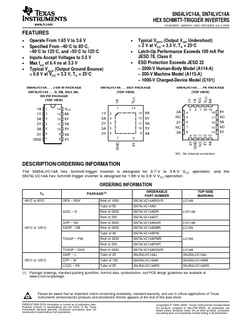
SNJ54ABT16825WD中文资料
PACKAGING INFORMATIONOrderable Device Status (1)Package Type Package Drawing Pins Package Qty Eco Plan (2)Lead/Ball Finish MSL Peak Temp (3)SN74ABT16825DL ACTIVE SSOP DL 5620Green (RoHS &no Sb/Br)CU NIPDAU Level-1-260C-UNLIM SN74ABT16825DLG4ACTIVE SSOP DL 5620Green (RoHS &no Sb/Br)CU NIPDAU Level-1-260C-UNLIM SN74ABT16825DLR ACTIVE SSOP DL 561000Green (RoHS &no Sb/Br)CU NIPDAU Level-1-260C-UNLIM SN74ABT16825DLRG4ACTIVESSOPDL561000Green (RoHS &no Sb/Br)CU NIPDAULevel-1-260C-UNLIM(1)The marketing status values are defined as follows:ACTIVE:Product device recommended for new designs.LIFEBUY:TI has announced that the device will be discontinued,and a lifetime-buy period is in effect.NRND:Not recommended for new designs.Device is in production to support existing customers,but TI does not recommend using this part in a new design.PREVIEW:Device has been announced but is not in production.Samples may or may not be available.OBSOLETE:TI has discontinued the production of the device.(2)Eco Plan -The planned eco-friendly classification:Pb-Free (RoHS),Pb-Free (RoHS Exempt),or Green (RoHS &no Sb/Br)-please check /productcontent for the latest availability information and additional product content details.TBD:The Pb-Free/Green conversion plan has not been defined.Pb-Free (RoHS):TI's terms "Lead-Free"or "Pb-Free"mean semiconductor products that are compatible with the current RoHS requirements for all 6substances,including the requirement that lead not exceed 0.1%by weight in homogeneous materials.Where designed to be soldered at high temperatures,TI Pb-Free products are suitable for use in specified lead-free processes.Pb-Free (RoHS Exempt):This component has a RoHS exemption for either 1)lead-based flip-chip solder bumps used between the die and package,or 2)lead-based die adhesive used between the die and leadframe.The component is otherwise considered Pb-Free (RoHS compatible)as defined above.Green (RoHS &no Sb/Br):TI defines "Green"to mean Pb-Free (RoHS compatible),and free of Bromine (Br)and Antimony (Sb)based flame retardants (Br or Sb do not exceed 0.1%by weight in homogeneous material)(3)MSL,Peak Temp.--The Moisture Sensitivity Level rating according to the JEDEC industry standard classifications,and peak solder temperature.Important Information and Disclaimer:The information provided on this page represents TI's knowledge and belief as of the date that it is provided.TI bases its knowledgeand belief on information provided by third parties,and makes no representation or warranty as to the accuracy of such information.Efforts are underway to better integrate information from third parties.TI has taken and continues to take reasonable steps to provide representative and accurate information but may not have conducted destructive testing or chemical analysis on incoming materials and chemicals.TI and TI suppliers consider certain information to be proprietary,and thus CAS numbers and other limited information may not be available for release.In no event shall TI's liability arising out of such information exceed the total purchase price of the TI part(s)at issue in this document sold by TI to Customer on an annual basis.PACKAGE OPTION ADDENDUM18-Jul-2006Addendum-Page 1IMPORTANT NOTICETexas Instruments Incorporated and its subsidiaries (TI) reserve the right to make corrections, modifications, enhancements, improvements, and other changes to its products and services at any time and to discontinue any product or service without notice. Customers should obtain the latest relevant information before placing orders and should verify that such information is current and complete. All products are sold subject to TI’s terms and conditions of sale supplied at the time of order acknowledgment.TI warrants performance of its hardware products to the specifications applicable at the time of sale in accordance with TI’s standard warranty. T esting and other quality control techniques are used to the extent TI deems necessary to support this warranty. Except where mandated by government requirements, testing of all parameters of each product is not necessarily performed.TI assumes no liability for applications assistance or customer product design. Customers are responsible for their products and applications using TI components. T o minimize the risks associated with customer products and applications, customers should provide adequate design and operating safeguards.TI does not warrant or represent that any license, either express or implied, is granted under any TI patent right, copyright, mask work right, or other TI intellectual property right relating to any combination, machine, or process in which TI products or services are used. Information published by TI regarding third-party products or services does not constitute a license from TI to use such products or services or a warranty or endorsement thereof. Use of such information may require a license from a third party under the patents or other intellectual property of the third party, or a license from TI under the patents or other intellectual property of TI.Reproduction of information in TI data books or data sheets is permissible only if reproduction is without alteration and is accompanied by all associated warranties, conditions, limitations, and notices. Reproduction of this information with alteration is an unfair and deceptive business practice. TI is not responsible or liable for such altered documentation.Resale of TI products or services with statements different from or beyond the parameters stated by TI for that product or service voids all express and any implied warranties for the associated TI product or service and is an unfair and deceptive business practice. TI is not responsible or liable for any such statements. Following are URLs where you can obtain information on other Texas Instruments products and application solutions:Products ApplicationsAmplifiers Audio /audioData Converters Automotive /automotiveDSP Broadband /broadbandInterface Digital Control /digitalcontrolLogic Military /militaryPower Mgmt Optical Networking /opticalnetwork Microcontrollers Security /securityLow Power Wireless /lpw Telephony /telephonyVideo & Imaging /videoWireless /wirelessMailing Address:Texas InstrumentsPost Office Box 655303 Dallas, Texas 75265Copyright 2006, Texas Instruments Incorporated。
SN54LVC14中文资料
9 10 11 12 13
4A
4Y
NC
GND
3Y
4Y
GND
NC - No internal connection
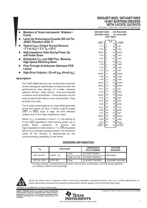
DESCRIPTION/ORDERING INFORMATION
The SN54LVC14A hex Schmitt-trigger inverter is designed for 2.7-V to 3.6-V VCC operation, and the SN74LVC14A hex Schmitt-trigger inverter is designed for 1.65-V to 3.6-V VCC operation.
元器件交易网
SN54LVC14A, SN74LVC14A HEX SCHMITT-TRIGGER INVERTERS
SCAS285X – MARCH 1993 – REVISED JULY 2005
FEATURES
• Operate From 1.65 V to 3.6 V
• Specified From –40°C to 85°C, –40°C to 125°C, and –55°C to 125°C
• Inputs Accept Voltages to 5.5 V
• Max tpd of 6.4 ns at 3.3 V • Typical VOLP (Output Ground Bounce)
PRODUCTION DATA information is current as of publication date. Products conform to specifications per the terms of the Texas Instruments standard warranty. Production processing does not necessarily include testing of all parameters.
SN74LVCH16245中文资料

元器件交易网IMPORTANT NOTICETexas Instruments and its subsidiaries (TI) reserve the right to make changes to their products or to discontinueany product or service without notice, and advise customers to obtain the latest version of relevant informationto verify, before placing orders, that information being relied on is current and complete. All products are soldsubject to the terms and conditions of sale supplied at the time of order acknowledgement, including thosepertaining to warranty, patent infringement, and limitation of liability.TI warrants performance of its semiconductor products to the specifications applicable at the time of sale inaccordance with TI’s standard warranty. Testing and other quality control techniques are utilized to the extentTI deems necessary to support this warranty. Specific testing of all parameters of each device is not necessarilyperformed, except those mandated by government requirements.CERTAIN APPLICATIONS USING SEMICONDUCTOR PRODUCTS MAY INVOLVE POTENTIAL RISKS OFDEATH, PERSONAL INJURY, OR SEVERE PROPERTY OR ENVIRONMENTAL DAMAGE (“CRITICALAPPLICATIONS”). TI SEMICONDUCTOR PRODUCTS ARE NOT DESIGNED, AUTHORIZED, ORWARRANTED TO BE SUITABLE FOR USE IN LIFE-SUPPORT DEVICES OR SYSTEMS OR OTHERCRITICAL APPLICATIONS. INCLUSION OF TI PRODUCTS IN SUCH APPLICATIONS IS UNDERSTOOD TOBE FULLY AT THE CUSTOMER’S RISK.In order to minimize risks associated with the customer’s applications, adequate design and operatingsafeguards must be provided by the customer to minimize inherent or procedural hazards.TI assumes no liability for applications assistance or customer product design. TI does not warrant or representthat any license, either express or implied, is granted under any patent right, copyright, mask work right, or otherintellectual property right of TI covering or relating to any combination, machine, or process in which suchsemiconductor products or services might be or are used. TI’s publication of information regarding any thirdparty’s products or services does not constitute TI’s approval, warranty or endorsement thereof.Copyright © 1998, Texas Instruments Incorporated。
SN65LV1224A中文资料
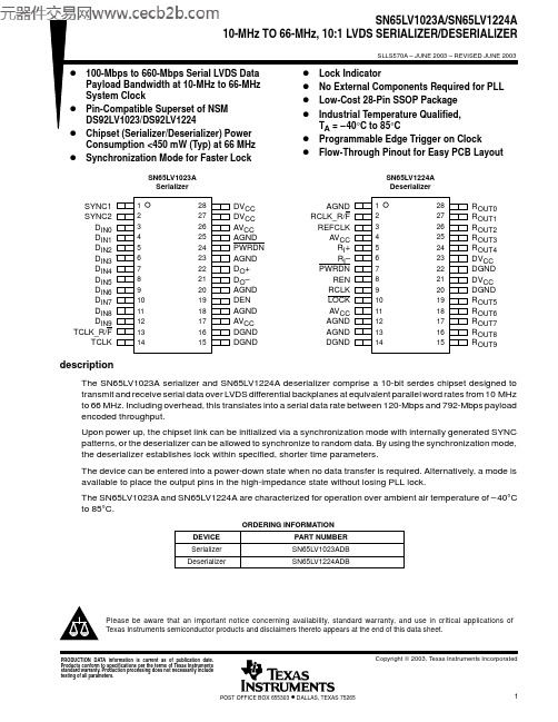
block diagrams
SN65LV1023A SN65LV1224A
LVDS Parallel-to-Serial Serial-to-Parallel 10 Input Latch DIN A+ A– Y+ Y– 10 Output Latch DOUT
functional description (continued)
synchronization mode The deserializer PLL must synchronize to the serializer in order to receive valid data. Synchronization can be accomplished in one of two ways:
D Rapid Synchronization: The serializer has the capability to send specific SYNC patterns consisting of six
ones and six zeros switching at the input clock rate. The transmission of SYNC patterns enables the deserializer to lock to the serializer signal within a deterministic time frame. This transmission of SYNC patterns is selected via the SYNC1 and SYNC2 inputs on the serializer. Upon receiving valid SYNC1 or SYNC2 pulse (wider than 6 clock cycles), 1026 cycles of SYNC pattern are sent. When the deserializer detects edge transitions at the LVDS input, it attempts to lock to the embedded clock information. The deserializer LOCK output remains high while its PLL locks to the incoming data or SYNC patterns present on the serial input. When the deserializer locks to the LVDS data, the LOCK output goes low. When LOCK is low, the deserializer outputs represent incoming LVDS data. One approach is to tie the deserializer LOCK output directly to SYNC1 or SYNC2.
74166中文资料

推荐工作条件:
电源电压VCC
输入高电平电压ViH 输入低电平电压ViL 输出高电平电流IOH 输出低电平电流IOL 时钟频率 fcp 脉冲宽度TW
建立时间 tset
保持时间tH
54 74
____ _
CLK, C L R
__ _
SH/ L D SER,A-H
最小 4.5 4.75 2
‘166 额定
____ _
CL R
清除端(低电平有效)
A-H SER QH
__ _
SH/L D
并行数据输入端 串行数据输入端 输出端
移位控制/置入控制(低电平有效)
封装图与逻辑图
双列直插封装
PLCC 封装
极限值 电源电压………………………………… 7V 输入电压………………………………… 5.5V 工作环境温度 54164…………………………………… -55~125℃ 74164…………………………………… -0~70℃ 储存温度……………………………………-65℃~150℃
54 Vcc=最大
74
单位
最大
5.5
V
5.25
V
0.8
V
-800
uA
16
mA
25
MHz
ns
ns ns ns
‘166 最小 最大
-1.5 2.4
0.4 1 40 -1.6 -20 -57 -18 -57
单位
V V V mA µA mA mA
ICC电源电流
Vcc=最大,SER 接 4.5V,除 CLK 外的其余输 入接地,CLK 瞬时接地后接 4.5V
__ _
当CLK INH为低电平,移位/置入控制端(SH/L D)为低电平,并行数据输
- 1、下载文档前请自行甄别文档内容的完整性,平台不提供额外的编辑、内容补充、找答案等附加服务。
- 2、"仅部分预览"的文档,不可在线预览部分如存在完整性等问题,可反馈申请退款(可完整预览的文档不适用该条件!)。
- 3、如文档侵犯您的权益,请联系客服反馈,我们会尽快为您处理(人工客服工作时间:9:00-18:30)。
SN54LV166A, SN74LV166A8-BIT PARALLEL-LOAD SHIFT REGISTERS
SCLS456A – FEBRUARY 2001 – REVISED JULY 2003
1POST OFFICE BOX 655303 • DALLAS, TEXAS 75265
D2-V to 5.5-V VCC OperationDMax tpd of 10.5 ns at 5 VDTypical VOLP (Output Ground Bounce)<0.8 V at VCC = 3.3 V, TA = 25°CDTypical VOHV (Output VOH Undershoot)>2.3 V at VCC = 3.3 V, TA = 25°CDIoff Supports Partial-Power-Down-ModeOperationDSynchronous LoadDDirect Overriding Clear
DParallel-to-Serial Conversion
DLatch-Up Performance Exceeds 100 mA Per
JESD 78, Class IIDESD Protection Exceeds JESD 22
– 2000-V Human-Body Model (A114-A)– 200-V Machine Model (A115-A)– 1000-V Charged-Device Model (C101)
SN54LV166A...J OR W PACKAGESN74LV166A...D, DB, DGV, NS, OR PW PACKAGE(TOP VIEW)
SN54LV166A...FK PACKAGE(TOP VIEW)
NC – No internal connection12345678
161514131211109
SERABCDCLK INHCLKGNDVCCSH/LDHQH
G
FECLR
32120199101112134
5678
1817161514
HQH
NC
GF
BCNCDCLK INH
ASERNCCLREVSH/LD
CLKGND
NC
CC
description/ordering informationThe ’LV166A devices are 8-bit parallel-load shift registers, designed for 2-V to 5.5-V VCC operation.ORDERING INFORMATIONTAPACKAGE†ORDERABLEPART NUMBERTOP-SIDEMARKING
SOICDTube of 40SN74LV166ADSOIC – DReel of 2500SN74LV166ADRLV166ASOP – NSReel of 2000SN74LV166ANSR74LV166A40Cto85SSOP – DBReel of 2000SN74LV166ADBRLV166A–40°C to 85°CTube of 90SN74LV166APW
TSSOP – PWReel of 2000SN74LV166APWRLV166AReel of 250SN74LV166APWTTVSOP – DGVReel of 2000SN74LV166ADGVRLV166ACDIP – JTube of 25SNJ54LV166AJSNJ54LV166AJ–55°C to 125°CCFP – WTube of 150SNJ54LV166AWSNJ54LV166AW
LCCC – FKTube of 55SNJ54LV166AFKSNJ54LV166AFK†Package drawings, standard packing quantities, thermal data, symbolization, and PCB design
guidelines are available at www.ti.com/sc/package.
Copyright 2003, Texas Instruments IncorporatedPlease be aware that an important notice concerning availability, standard warranty, and use in critical applications ofTexasInstruments semiconductor products and disclaimers thereto appears at the end of this data sheet.
UNLESS OTHERWISE NOTED this document contains PRODUCTIONDATA information current as of publication date. Products conform tospecifications per the terms of Texas Instruments standard warranty.Production processing does not necessarily include testing of allparameters.SN54LV166A, SN74LV166A8-BIT PARALLEL-LOAD SHIFT REGISTERS
SCLS456A – FEBRUARY 2001 – REVISED JULY 2003
2POST OFFICE BOX 655303 • DALLAS, TEXAS 75265
description/ordering information (continued)The ’LV166A parallel-in or serial-in, serial-out registers feature gated clock (CLK, CLK INH) inputs and anoverriding clear (CLR) input. The parallel-in or serial-in modes are established by the shift/load (SH/LD) input.When high, SH/LD enables the serial (SER) data input and couples the eight flip-flops for serial shifting with eachclock (CLK) pulse. When low, the parallel (broadside) data inputs are enabled, and synchronous loading occurson the next clock pulse. During parallel loading, serial data flow is inhibited. Clocking is accomplished on thelow-to-high-level edge of CLK through a 2-input positive-NOR gate, permitting one input to be used as aclock-enable or clock-inhibit function. Holding either CLK or CLK INH high inhibits clocking; holding either lowenables the other clock input. This allows the system clock to be free running, and the register can be stoppedon command with the other clock input. CLK INH should be changed to the high level only when CLK is high.CLR overrides all other inputs, including CLK, and resets all flip-flops to zero.
These devices are fully specified for partial-power-down applications using Ioff. The Ioff circuitry disables the
outputs, preventing damaging current backflow through the devices when they are powered down.
FUNCTION TABLEOUTPUTSINPUTSINTERNAL
CLRSH/LDCLK INHCLKSERPARALLELA...HQAQB
QH
LXXXXXLLLHXLLXXQA0QB0QH0
HLL↑Xa...habhHHL↑HXHQAnQGn
HHL↑LXLQAnQGn
HXH↑XXQA0QB0QH0