HK110 Maintenance Manual
海卓公司 CS-110 系列自动切换系统操作维护手册说明书

CS-110CS-110 Rev. 4/22/15这份海卓公司文件以英文版Instruction pages(CS-110)为准。
本翻译版本仅是为用户提供方便所有海卓公司的产品说明书都能在海卓公司的网站www.instruments.com找到翻译免责声明操作维护手册自 动 切 换 系 统104、主屏幕布局......... (3)I. (3)II. (5)III. (7)IV............................................................................................................................................................................................................ 4 .. (6)............................................................................ 8 .. (9)海卓公司CS-110系列自动切换系统目录安全信息概述1、内容2、一般规格3、功能概述安装说明1、电气连接2、概述1、按键操作2、LED显示说明3、基本操作4、Modbus通讯操作说明维护图示1、典型的系统安装图2、CS-110内部接线图3、CS-110显示屏流程图显示屏将会显示日期、时间、每组氯瓶的工作时间(电动球阀的开启时间)及(可选的)将显示系统的操作情况。
2个4-20mA输入通道可接收电子秤的信号,此功能是可选功能。
控制器接收两个压力开关信号,并提供控制信号对电动球阀进行操作。
LED和LCD指示灯功能介绍:外形尺寸:板和电源的任何部分。
电气:电路板和电路线都可能引起电击或电路,在确认电源已经断开之前,请不要触摸电路总述:在操作此设备之前,确保遵循所有的安全警示。
MM110安全指南说明书

ITEM MM110Table of contentsSafety (3)Specifications (6)Setup (6)Operation ....................................................7Maintenance .. (8)Parts List and Diagram (10)Page 2General Tool Safety WarningsRead all safety warnings and instructions.Failure to follow the warnings and instructions may result in electric shock, fire and/or serious injury. Save all warnings and instructions for future reference.1. KEEP GUARDS IN PLACE and in working order.2. REMOVE ADJUSTING KEYS AND WRENCHES.Form habit of checking to see that keys and adjustingwrenches are removed from tool before turning it on.3. KEEP WORK AREA CLEAN.Cluttered areas and benches invite accidents.4. DON’T USE IN DANGEROUS ENVIRONMENT.Don’t use power tools in damp or wet locations,or expose them to rain. Keep work area well lighted.5. KEEP CHILDREN AWAY. All visitors shouldbe kept safe distance from work area.6. MAKE WORKSHOP KID PROOF with padlocks,master switches, or by removing starter keys.7. DON’T FORCE TOOL. It will do the job betterand safer at the rate for which it was designed.8. USE RIGHT TOOL. Don’t force tool or attachmentto do a job for which it was not designed.Table A: REcOMMENDED MINIMUM WIRE GAUGEFOR EXTENSION cORDS(120 VOLT)NAMEpLATE AMpERES (at full load)EXTENSION cORDLENGTH25′ 50′ 100′ 150′0 – 6181616146.1 – 101816141210.1 – 121616141212.1 – 161412Do not use.9. USE PROPER EXTENSION CORD. Make sure yourextension cord is in good condition. When usingan extension cord, be sure to use one heavyenough to carry the current your product willdraw. An undersized cord will cause a drop in linevoltage resulting in loss of power and overheating.Table A shows the correct size to use dependingon cord length and nameplate ampere rating.If in doubt, use the next heavier gauge.The smaller the gauge number, the heavier the cord.10. WEAR PROPER APPAREL. Do not wearloose clothing, gloves, neckties, rings, bracelets,or other jewelry which may get caught inmoving parts. Nonslip footwear is recommended.Wear protective hair covering to contain long hair.11. ALWAYS USE SAFETY GLASSES. Also useface or dust mask if cutting operation is dusty.Everyday eyeglasses only have impact resistantlenses, they are NOT safety glasses.12. SECURE WORK. Use clamps or a vise to holdwork when practical. It’s safer than using yourhand and it frees both hands to operate tool.13. DON’T OVERREACH. Keep properfooting and balance at all times.14. MAINTAIN TOOLS WITH CARE. Keep tools sharpand clean for best and safest performance. Followinstructions for lubricating and changing accessories.15. DISCONNECT TOOLS before servicing;when changing accessories, such asblades, bits, cutters, and the like.16. REDUCE THE RISK OF UNINTENTIONALSTARTING. Make sure switch is inoff position before plugging in.17. USE RECOMMENDED ACCESSORIES.Consult the owner’s manual for recommendedaccessories. The use of improper accessoriesmay cause risk of injury to persons.18. NEVER STAND ON TOOL. Serious injurycould occur if the tool is tipped or if thecutting tool is unintentionally contacted.19. CHECK DAMAGED PARTS. Before further useof the tool, a guard or other part that is damagedshould be carefully checked to determine thatit will operate properly and perform its intendedfunction – check for alignment of moving parts,binding of moving parts, breakage of parts,mounting, and any other conditions that mayaffect its operation. A guard or other part that isdamaged should be properly repaired or replaced.20. DIRECTION OF FEED. Feed work intoa blade or cutter against the direction ofrotation of the blade or cutter only.21. NEVER LEAVE TOOL RUNNING UNATTENDED.TURN POWER OFF. Don’t leave tooluntil it comes to a complete stop.Page 3TO pREVENT ELEcTRIc SHOcK AND DEATH FROM INcORREcT GROUNDING WIRE cONNEcTION READ AND FOLLOW THESE INSTRUcTIONS:110-120 V~ Grounded Tools: Tools with Three prong plugs1. In the event of a malfunction or breakdown,grounding provides a path of least resistance forelectric current to reduce the risk of electric shock.This tool is equipped with an electric cord having an equipment-grounding conductor and a groundingplug. The plug must be plugged into a matchingoutlet that is properly installed and grounded inaccordance with all local codes and ordinances. 2. Do not modify the plug provided – if it willnot fit the outlet, have the proper outletinstalled by a qualified electrician.3. Improper connection of the equipment-groundingconductor can result in a risk of electric shock.The conductor with insulation having an outersurface that is green with or without yellowstripes is the equipment-grounding conductor.If repair or replacement of the electric cord orplug is necessary, do not connect the equipment-grounding conductor to a live terminal.4. Check with a qualified electrician or servicepersonnel if the grounding instructions arenot completely understood, or if in doubt asto whether the tool is properly grounded.5. Use only 3-wire extension cords thathave 3-prong grounding plugs and 3-polereceptacles that accept the tool’s plug.6. Repair or replace damaged or worn cord immediately.125 V~ 3-prong plug and Outlet(for up to 125 V~ and up to 15 A)Groundingpin7. This tool is intended for use on a circuit that hasan outlet that looks like the one illustrated abovein 125 V~ 3-prong plug and Outlet. The tool hasa grounding plug that looks like the plug illustratedabove in 125 V~ 3-prong plug and Outlet.8. The outlet must be properly installed and groundedin accordance with all codes and ordinances.9. Do not use an adapter to connectthis tool to a different outlet.Sander Safety WarningsFor your Own Safety Read InstructionManual Before Operating Sander1. Wear eye protection.2. Support workpiece with worktable.3. Maintain 1/16 inch maximum clearancebetween table and sanding disc.4. Avoid kickback by sanding in accordancewith the directional arrows.5. The backstop is a fence near the surface thathelps the operator maintain control of theworkpiece and prevents the workpiece from being pulled into the machine. For safety, it must beadjusted very close to the sanding surface.6. The worktable is the surface mounted close tothe sanding surface that the operator rests theworkpiece against to prevent it from being pulledby the sanding surface. For safety, it must beadjusted very close to the sanding surface.7. Sand only on the downward moving surfaceof the disc - sanding on the upward movingsurface may result in the workpiece beingthrown up and towards the operator.8. DO NOT OpERATE WITH ANy GUARDDISABLED, DAMAGED, OR REMOVED.9. The use of accessories or attachments notrecommended by the manufacturer mayresult in a risk of injury to persons.10. When servicing use only identical replacement parts.Page 411. Only use safety equipment that has been approvedby an appropriate standards agency. Unapprovedsafety equipment may not provide adequateprotection. Eye protection must be ANSI-approved and breathing protection must be NIOSH-approved for the specific hazards in the work area.12. Stay alert, watch what you are doing and usecommon sense when operating a power tool.Do not use a power tool while you are tired orunder the influence of drugs, alcohol or medication.A moment of inattention while operating powertools may result in serious personal injury.13. Industrial applications must follow OSHA guidelines.14. Maintain labels and nameplates on the tool.These carry important safety information.If unreadable or missing, contactHarbor Freight Tools for a replacement.15. Avoid unintentional starting.Prepare to begin work before turning on the tool. 16. People with pacemakers should consult theirphysician(s) before use. Electromagnetic fields inclose proximity to heart pacemaker could causepacemaker interference or pacemaker failure.17. WARNING: Some dust created by powersanding, sawing, grinding, drilling, and otherconstruction activities, contains chemicalsknown [to the State of California] to causecancer, birth defects or other reproductive harm.Some examples of these chemicals are:• Lead from lead-based paints• Crystalline silica from bricks and cement or othermasonry products• Arsenic and chromium fromchemically treated lumberYour risk from these exposures varies,depending on how often you do this type of work.To reduce your exposure to these chemicals:work in a well ventilated area, andwork with approved safety equipment, suchas those dust masks that are speciallydesigned to filter out microscopic particles.(California Health & Safety Code § 25249.5, et seq.)18. WARNING: Handling the cord on this product willexpose you to lead, a chemical known to the Stateof California to cause cancer, and birth defects orother reproductive harm. Wash hands after handling.(California Health & Safety Code § 25249.5, et seq.)19. The warnings, precautions, and instructionsdiscussed in this instruction manual cannotcover all possible conditions and situationsthat may occur. It must be understood by theoperator that common sense and caution arefactors which cannot be built into this product,but must be supplied by the operator.Vibration SafetyThis tool vibrates during use. Repeated or long-term exposure to vibration may cause temporary or permanent physical injury, particularly to the hands, arms and shoulders. To reduce the risk of vibration-related injury: 1. Anyone using vibrating tools regularly or for anextended period should first be examined by adoctor and then have regular medical check-upsto ensure medical problems are not being causedor worsened from use. Pregnant women orpeople who have impaired blood circulation tothe hand, past hand injuries, nervous systemdisorders, diabetes, or Raynaud’s Disease shouldnot use this tool. If you feel any medical orphysical symptoms related to vibration (such astingling, numbness, and white or blue fingers),seek medical advice as soon as possible.2. Do not smoke during use. Nicotine reducesthe blood supply to the hands and fingers,increasing the risk of vibration-related injury.3. Use tools with the lowest vibration when thereis a choice between different processes.4. Include vibration-free periods each day of work.5. Grip tool as lightly as possible (while still keepingsafe control of it). Let the tool do the work.6. To reduce vibration, maintain the tool asexplained in this manual. If any abnormalvibration occurs, stop use immediately.SAVE THESE INSTRUcTIONS.Sander Safety Warnings (cont.)Page 5Electrical Rating120V~ / 60Hz / 5A No Load Speed1750 RPMTable12″ x 5-5⁄8″0 - 45° tiltAccessory Diameter 10″ (250mm)Sanding Disc TypePSA (PressureSensitive Adhesive)Dust PortØ1-3⁄8″Read the ENTIRE IMpORTANT SAFETy INFORMATION section at the beginning of this manual including all text under subheadings therein before set up or use of this product.TO pREVENT SERIOUS INJURy FROM AccIDENTAL OpERATION:Turn the power Switch of the tool off and unplug the tool from its electrical outlet before performing any procedure in this section.Note: For additional information regarding the parts listed in the following pages, refer to the Assembly Diagram near the end of this manual.Assembly/Mounting1. Place a Table Handle (3) on the top of eachTable Screw (4) at the ends of the Worktable (52).2. Secure each Table Handle (3) in place witha Screw (1) and Spring (2). (See Figure A.)3. Secure Sander to table or workbenchusing suitable hardware (sold separately)through holes at bottom of Base (43).4. Connect a dust collector hose orvacuum hose (sold separately) securely tothe dust port on the Dust Cover (49).Screw (1)andSpring (2)TableHandle (3)Figure A: Table Handle InstallationSwitchMiter Gauge Table HandleDust portWorktableSanding DiscFigure B: Functions227541Page 6Read the ENTIRE IMpORTANT SAFETy INFORMATION section at the beginning of thismanual including all text under subheadings therein before set up or use of this product. Tool Set UpTO pREVENT SERIOUS INJURy FROM AccIDENTAL OpERATION:Turn the power Switch of the tool off and unplug the tool from itselectrical outlet before performing any procedure in this section.TO pREVENT SERIOUS INJURy:DO NOT OpERATE WITH ANy GUARD DISABLED, DAMAGED, OR REMOVED.Sanding Disc Attachment1. Remove all pieces of old sanding discsand adhesive from the Backing Disc.2. Make sure the Backing Disc is clean and dry.3. Peel backing paper off a 10″ sanding disc(sold separately), and apply it carefullyto the Backing Disc. Smooth it againstthe disc to eliminate air bubbles.Miter Angle1. Place the Miter Gauge into the slot on the Worktable.2. Loosen the Knob on the Miter Gauge.3. Set the desired sanding angle andtighten the Knob on the Miter Gauge.Worktable Angle1. Loosen both Table Handles.2. Move the Worktable to the desired angle.3. Hold Worktable in place whiletightening both Table Handles.Workpiece and Work Area Set Up1. Designate a work area that is clean and well-lit.The work area must not allow access by children or pets to prevent distraction and injury.2. Route the power cord along a safe route to reachthe work area without creating a tripping hazardor exposing the power cord to possible damage.3. There must not be objects, such as utility lines,nearby that will present a hazard while working.General Operating Instructions1. Turn on dust collector/vacuum.2. Turn on Sander and allow it to come tofull speed before starting to sand.3. Support workpiece with worktable.Do not sand freehand.4. cAUTION! Sand only on the downward movingsurface of the disc - sanding on the upwardmoving surface may result in the workpiecebeing thrown up and towards the operator.5. To prevent accidents, turn off the tool anddisconnect its power supply after use. Clean, then store the tool indoors out of children’s reach.Page 7procedures not specifically explained in this manual mustbe performed only by a qualified technician.TO pREVENT SERIOUS INJURy FROM AccIDENTAL OpERATION: Turn the power Switch of the tool off and unplug the tool from its electrical outlet before performing any procedure in this section. TO pREVENT SERIOUS INJURy FROM TOOL FAILURE:Do not use damaged equipment. If abnormal noise or vibration occurs, have the problem corrected before further use. cleaning, Maintenance, and Lubrication1. BEFORE EAcH USE, inspect the generalcondition of the tool. Check for:• loose hardware,• misalignment or binding of moving parts, • cracked or broken parts,• damaged electrical wiring, and• any other condition that mayaffect its safe operation.2. AFTER USE, wipe external surfacesof the tool with clean cloth.3. Replace sanding disc if torn or excessivelyworn to prevent workpiece damage.4. WARNING! If the supply cord of thispower tool is damaged, it must be replaced only by a qualified service technician.Page 8TroubleshootingPage 9part Description Qty 1Screw2 2Spring2 3Table Handle2 4Table Screw2 5Screw "A"2 6Left Table Bracket1 7End Cap "B"1 8Gauge Sliding Bar1 9Miter Gauge1 10Pointer1 11Flat Washer 44 12Elastic Washer 44 13Screw M4×101 14Locking Knob 1 15Cap Screw M5×125 16Elastic Washer 512 17Rubber Feet4 18Cross Screw M4×121 19Pointer1 20Cross Screw M5×61 21Toothed Washer 51 22Screw M5×81 23Capacitor1 24Capacitor Clip1 25Screw M5×101 26Switch1 27Screw ST2.9×144 28Switch Plate1part Description Qty 29Cord Plug1 30Wire Grip1 31Screw M5×125 32Flat Washer 510 33Terminal Box1 34Fan Cover1 35Screw M4×123 36Gasket Washer3 37Fan 1 38Nut M54 39End Cover1 40Stator1 41Motor Housing1 42Rotor1 43Base1 44Screw M5×1554 45Flat Key 5×101 46Backing Disc1 47Washer1 48Sanding Disc1 49Dust Cover1 50Right Table Bracket1 51End Cap "A"1 52Worktable1 53Bolt M6×166 54Flat Washer 66 55Elastic Washer 66 56Nut M66pLEASE READ THE FOLLOWING cAREFULLyTHE MANUFACTURER AND/OR DISTRIBUTOR HAS PROVIDED THE PARTS LIST AND ASSEMBLY DIAGRAM IN THIS MANUAL AS A REFERENCE TOOL ONLY. NEITHER THE MANUFACTURER OR DISTRIBUTOR MAKES ANY REPRESENTATION OR WARRANTY OF ANY KIND TO THE BUYER THAT HE OR SHE IS QUALIFIED TO MAKE ANY REPAIRS TO THE PRODUCT, OR THAT HE OR SHE IS QUALIFIED TO REPLACE ANY PARTS OF THE PRODUCT. IN FACT, THE MANUFACTURER AND/OR DISTRIBUTOR EXPRESSLY STATES THAT ALL REPAIRS AND PARTS REPLACEMENTS SHOULD BE UNDERTAKEN BY CERTIFIED AND LICENSED TECHNICIANS, AND NOT BY THE BUYER. THE BUYER ASSUMES ALL RISK AND LIABILITY ARISING OUT OF HIS OR HER REPAIRS TO THE ORIGINAL PRODUCT OR REPLACEMENT PARTS THERETO, OR ARISING OUT OF HIS OR HER INSTALLATION OF REPLACEMENT PARTS THERETO. parts ListNote: Some parts are listed and shown for illustration purposes only,and are not available individually as replacement parts.Page 10Page 11Assembly Diagram。
Component Maintenance Manual
Gary Bussett2013.03.0412:29:25 -08'00'Melissa Moisant2013.03.04 17:08:43-08'00'Burt Tanaka2013.03.04 18:10:18-08'00'__________________________________________________________________________________________SUBJECTComponent Maintenance ManualCAGE CODE64818 DATE 10/04/05 SECTION PAGE i of i REVISION BCOMPONENT MAINTENANCE MANUALFORFCI PN 015838WATER LEVEL & TEMP MONITORING SYSTEMFORCANADAIRApprovals:OriginatorContractsQuality AssuranceNOTICE OF PROPRIETARY RIGHTSThis document contains confidential technical data, including trade secrets and propriety informationwhich is the property of Fluid Components International LLC (FCI). Disclosure of this data to you isexpressly conditional upon your assent that its use is limited to use within your company only (and does not include manufacture or processing uses). Any other use is strictly prohibited without prior writtenconsent of FCI.SUBJECTComponent Maintenance Manual CAGE CODE64818 DATE 10/04/05 SECTION PAGE i of ii REVISION B REVISION PAGERev. Description Date -Initial Release 05/15/95A Revised Part Numbers in Figures 1, 3, and 5 02/12/97B Introduction – Changed company name; Figure 3 – Changed Control Unit label;Sect 2.B. Control Unit – Added para. 5 describing differences between -02 and-03; All -Combined sections into single file.10/04/05COMPONENT MAINTENANCE MANUALFCI Document Control Number: 06EN003252 Rev. BWATER LEVEL AND TEMPERATURE MONITORING SYSTEMPART NUMBER: 015838NOTICE OF PROPRIETARY RIGHTSThis document contains confidential technical data, including trade secretsand proprietary information which are the property of Fluid ComponentsIntl (FCI).Disclosure of this data to you is expressly conditioned upon your assentthat its use is limited to use within your company only (and does notinclude manufacture or processing uses). Any other use is strictlyprohibited without the prior written consent of FCI.THIS PAGE INTENTIONALLY LEFT BLANKRECORD OF REVISIONSTHIS PAGE INTENTIONALLY LEFT BLANKRECORD OF TEMPORARY REVISIONSTHIS PAGE INTENTIONALLY LEFT BLANKPART NUMBER 015838SERVICE BULLETIN LISTService Bulletin information is placed in this list when the Service Bulletin is incorporated into this manual.PART NUMBER 015838 THIS PAGE INTENTIONALLY LEFT BLANKLIST OF EFFECTIVE PAGESTHIS PAGE INTENTIONALLY LEFT BLANKTABLE OF CONTENTSPARAGRAPH TITLE PAGE Introduction . . . . . . . . . . . . . . . . . . . . . . . . . . . . . . . . . . . . . . . . . . . . . . . . . . . . . . . 1 Description and Operation . . . . . . . . . . . . . . . . . . . . . . . . . . . . . . . . . . . . . . . . . . . 2 Testing . .. . . . . . . . . . . . . . . . . . . . . . . . . . . . . . . . . . . . . . . . . . . . . . . . . . . . . . . . 7 Cleaning . . . . . . . . . . . . . . . . . . . . . . . . . . . . . . . . . . . . . . . . . . . . . . . . . . . . . . . . . 9 Inspection/Check . . . . . . . . . . . . . . . . . . . . . . . . . . . . . . . . . . . . . . . . . . . . . . . . . . 9 Repair . . . . . . . . . . . . . . . . . . . . . . . . . . . . . . . . . . . . . . . . . . . . . . . . . . . . . . . . . . . 9THIS PAGE INTENTIONALLY LEFT BLANKINTRODUCTION1. GeneralA. This manual provides maintenance instructions for the Model 015838 Water Level andTemperature Monitoring System.B. The information in this abbreviated manual covers the description, operation, testing, cleaning, andinspection of this equipment.C. The instrument is manufactured by Fluid Components International LLC, San Marcos,California (CAGE CODE 64818), for Bombardier Inc. Canadair Group.2. Ordering of PartsOrder of parts are to be directed as follows:Fluid Components Intl1755 La Costa Meadows DriveSan Marcos, California 92069-5187Attention: Customer SalesPhone: (800) 854-1993 or (760) 744-6950 or FAX: (760) 736-62503. Manual RequestsRequests for copies of publications should be directed to the address shown in Paragraph 2.4. Manual RevisionsThis manual will be revised as necessary to reflect current information.DESCRIPTION AND OPERATION1. DescriptionThe Model 015838 Water Level and Temperature Monitoring System monitors the potable water in aircraft potable water tanks. Figure 1 shows the Water Level and Temperature Monitoring System. The system consists of 2 probes that are in physical contact with the potable water, and control circuitry that produces output signals that indicate water level, turn on water heaters, and inhibit pump operations. The system has no moving parts, is lightweight, compact, and reliable. The typical application for the system is to monitor aircraft galley and lavatory potable water tanks. The physical and operational characteristics of the system are listed in Figure 2. Figure 3 shows the outline dimensions of the system for purposes of proper mounting.Water Level and Temperature Monitoring SystemFigure 1Figure 2Outline DimensionsFigure 32. OperationA. ProbeOne probe is screwed into each potable water tank. (A customer supplied O-Ring packing is suggested for use with each probe.) Each probe consists of two polymer strips that contain Resistance Temperature Detectors (RTD)’s. The strips are placed parallel to each other in a sectioned tube. One strip, known as the reference strip, contains two RTD’s. The other strip, known as the active strip, contains five RTD’sThe reference strip contains one RTD for level measurement and one RTD for watertemperature measurement. The active strip contains five RTD’s. All five RTD’s in the active strip are used for level detection. See the probe configuration in Figure 4.When the probe is put in water, the submerged portion of the reference strip is at the watertemperature. The active strip is heated by an electric current and loses some heat to thewater. A Temperature Differential (∆T) exists between the active and reference RTD stripsand a proportional Resistance Differential (∆R) exists that the control unit measures.B. Control UnitThe input to the control unit circuitry is the ΔR. The output of the control unit circuitry isground (enable) or open (disable) signals.The control unit has a two minute warm up period from power up to operation. During thistime the empty level signals, the 1/4 level signals, the 1/2 level signals, the 3/4 level signalsand the full level signals will be enabled one at a time. Then all signals will be disabled. This sequence will repeat every six seconds for the two minute warm up time.The control unit P/N 015840-01 circuitry enables or disables a pump inhibit signal. If thepower has been off for more than 20 ±5 minutes the circuitry will enable the pump inhibitsignal at power up. The pump inhibit signal will be enabled for 15 minutes after power up. If power has been removed and then powered on again within 20 ±5 minutes there will be apump inhibit signal enabled for only the 2 minute warm up period. The pump inhibit signal is also enabled whenever the potable water level is below the empty level on the probe.The control unit P/N 015840-02 is different from the -01 control unit as follows: When amomentary power interrupt occurs, the -02 control unit will bypass the 2 minute warm-upperiod and go directly into displaying the level.The control unit P/N 015480-03 is different from the -02 control unit as follows: The unit has short circuit protection on the signal outputs and reset circuitry to prevent control boxsoftware lock-up.The second RTD in the reference RTD strip along with the control unit circuitry measures the water temperature. For probe #1 (short probe); when the water temperature decreasesbelow 50°F (10°C) the temperature signal is enabled. When the water temperatureincreases above 68°F (20°C) the temperature signal is disabled. For probe #2 (long probe);when the water temperature decreases below 59°F (15°C) the temperature signal is enabled.When the water temperature increases above 95°F (35°C) the temperature signal isdisabled.The control unit detects if there is a probe failure (short or open). If a failure is detected all of the probe level signals are enabled simultaneously for one second, then disabled simultaneously for 5 seconds. The pump inhibit signal is enabled (disabling the pump) and the temperature signal is disabled (removing power to the heater).Probe ConfigurationFigure 4TESTING1. GeneralThe system is easy to troubleshoot due to the simplicity of design. System failures can be as simple to correct as unscrewing a probe and screwing in a new one.2. Test EquipmentPrecision Digital Multi-Meter (DMM)3. Test ProcedureWARNING: ONLY QUALIFIED PERSONNEL SHOULD ATTEMPT TO TEST THIS SYSTEM. THE OPERATOR ASSUMES ALL RESPONSIBILITIES FOR SAFE PRACTICES WHILE TROUBLESHOOTING.A. Verify error: All lights in the aircraft’s potable water monitoring device for probe 1 flash for1 second every 5 seconds. The control unit is not receiving correct signals from probe 1.(1) Check for bent connector pins in control unit enclosure and probe 1 connector (shortprobe for galley potable water tank).(2) Check probe 1 resistances as found on the schematics in Figure 4. The resistancevalues shown are taken at 32°F (0°C). At 68°F (20°C) the resistance is 272±8 ohms.(3) Check the aircraft components that mate with the system for problems. See Figure 5 fora wiring diagram of the system.B. Verify error: All lights in the aircraft’s potable water monitoring device for probe 2 flash for1 second every 5 seconds. The control unit is not receiving correct signals from probe 2.(1) Check for bent connector pins in control unit enclosure and probe 2 connector (longprobe for lavatory potable water tank).(2) Check probe 2 resistances as found on the schematics in Figure 4. The resistancevalues shown are taken at 32°F (0°C). At 68°F (20°C) the resistance is 272±8 ohms.(3) Check the aircraft components that mate with the system for problems. See Figure 5 fora wiring diagram of the system.C. Verify error: No lights lit in the aircraft’s potable water monitoring device during warm upsequence.(1) Check for power to the control unit. See Figure 5. (No lights lit after warm up indicatethat the water level is below the empty level of the probe.)D. Verify error: Lights in the aircraft’s potable water monitoring device indicate incorrect level.(1) Verify the correct probe is in the correct tank. The long 19.86 inch (504 mm) probe isused in the lavatory potable water tank. The short 9.82 inch (248 mm) probe is used inthe galley potable water tank. (The water tanks may not be entirely empty, however if thewater is below the probe the system will register empty.)(2) Remove the probe with the incorrect indication. Remove any ice from the probe.Reinstall the probe.Wiring DiagramFigure 54. ConclusionIf the above conditions have been verified and problems are still being experienced contact the FCI Customer Service Department as shown in paragraph 2 of the introduction.If any units are defective contact FCI Customer Service Department and arrange to have the system unit sent back for repair or replacement.CLEANING1. Cleaning SolutionsA. Isopropyl AlcoholB. Aqueous cleaning / disinfectant solution compatible with potable water containers2. CleaningA. Remove foreign material from the external surfaces of the control unit enclosure with a clothmoist with an aqueous cleaning / disinfectant solution.B. Clean the connectors and pins with isopropyl alcohol and a cotton swab.C. Clean the probe body by dipping it into an aqueous cleaning / disinfectant solution. Do not useorganic solvents on the plastic materials. Dry with a clean cloth.INSPECTION/CHECK1. Control Circuit Enclosure ConditionVisually inspect the control unit enclosure periodically for physical damage. The enclosure should be free of corrosion and cracks.2. Probe ConditionVisually inspect the probe portion of the system for physical damage. The probe should be free of corrosion and cracks.REPAIRThe system is not field repairable other than the removal and replacement of the probes or the control unit enclosure. If the system fails to operate properly return the system unit(s) to FCI at the address in paragraph 2 of the Introduction. There is no need to return all of the system units if just one unit is faulty.THIS PAGE INTENTIONALLY LEFT BLANK。
SV110 使用手册说明书

SV110 user's manualSV 110PORTABLE VIBRATIONCALIBRATOR Warsaw, August 2016 Copyright © 2015 SVANTEK. All rights reserved.SV110 user's manualof its life. Instead, hand it in at an official collection point for recycling. By doing this you will help to preserve the environment.TrademarksMicrosoft and Windows are registered trademarks of Microsoft CorporationCopyright © 2015, SVANTEK sp. z o.o.All rights reserved. No part of this publication may be reproduced or distributed in any form, or by any means, without prior written consent from SVANTEK, Warsaw, PolandSV110 user's manualCONTENTS1. General safety summary (4)2. Calibration (4)3. Accuracy of calibration (5)4. SV110 model information (5)5. Unpacking and Inspecting the package contents (6)6. Getting started (7)7. Manual control of the calibrator (8)7.1. Turning on/off (8)7.2. Menu content (9)8. Calibration (11)9. General Care and Cleaning (13)10. Charging (14)11. Technical data (16)12. Recalibration of SV110 (14)Document history (17)SV110 user's manual1. General safety summaryReview the following safety precautions to avoid injury and prevent from damaging this product or other products connected with it. To avoid potential hazards, use this product only as specified. Qualified personnel should only perform the service procedures.Warnings, precautions and maintenance:Use a proper AC/DC adapter, specified for this product and certified for the country of its use.Keep the product’s surfaces clean and dry.Even when the device is not in use it is recommended to charge the battery once a month to keep it in good stateIt is recommended to carry out a technical inspection and recalibration of the device every 12 months to ensure accurate calibration levelRecalibration can be made by the calibration laboratory. If there is no possibility to recalibrate the device by calibration laboratory the device should be send to the manufacturer.All maintenance work and repairs can only be done by the personnel trained by the manufacturer.Handle with careSafety terms and symbols:2. CalibrationOne of the fundamental questions, that are most frequently asked while taking a measurement, is whether its result is accurate. Proceeding, with a measurement without having a positive answer to this question, may result in obtaining data of no practical use and wasting our time. However, we may easily obtain the answer by performing a calibration of the vibration level meter using vibration calibrator. This device should be used before every set of measurements.The vibration calibrator is a device, which produces the vibration of the defined levels and frequency. It allows to calibrate the vibration meter in comparative way.SV110 user's manualCalibration procedure is also the best way for the complete measuring system (Meter, Cable and Transducer connected together) check. This is an essential action for the reliable measurements performed in the field!3. Accuracy of calibrationEach measurement performed by any measurement device is burdened with an error. Result obtained from such measurement is only an estimate of the real value of the measured quantity. Hence, the purpose of calibration is to limit this inevitable error to a certain acceptable level. Maximum absolute value of the error of the generated vibration signals is called the tolerance and is strictly defined by the standard ISO8041:2005.4. SV110 model informationThe SV 110 is a hand-held vibration calibrator designed for verification of machine sensors as well as on-site checks of human vibration accelerometers in accordance to ISO 8041:2005.The two standard frequencies 79.58 and 159.2 Hz brings opportunity to calibrate wide range of an existing transducers with maximum load of 0.3 kg.Depending on the selected frequency, the user can select the level of the calibration from 1 m/s2 to 10 m/s2.Because of its own internal rechargeable battery, it is a truly mobile and flexible device designed to use either in a laboratory or during fieldwork.The light weight of the calibrator allows to perform transducers calibration in the field conditions keeping it in hands.Two diodes indicate the external vertical and horizontal vibration that can affect the tolerances specified by the ISO8041:2005.Accelerometers are conveniently attached using either a mounting stud, a mounting disc or a dedicated adapters. The calibrator has built-in rechargeable batteries that power it for 12 hours of continuous operation*.The calibrator has a robust casing with the leather cover forhand-arm in field use.*) In case of 79.58 Hz frequency and accelerometer weight less than 200g. For other frequency and/or accelerometer weight continuous operation time will be shorter.SV110 user's manual5. Unpacking and Inspecting the package contentsIf the device has been kept or transported in low temperature (below 0 °C), it is recommended to leave it for a few hours in room temperature before connecting it to the power supply. If any steam condensation appears, it is recommended not to connect the device to the mains electricity for 4 to 8 hours until the exterior surface is dry.Despite careful packing, the risk of the device damage cannot be entirely eliminated.Upon delivery, please make sure that the device is not damaged and verify that you received the ordered equipment and optional accessories (if ordered). In case of any problems, please contact an authorized Svantek representative, the service staff or the manufacturer directly.Before the first use of the device, in order to charge the battery completely, connect SA 54 AC/DC adapter plug to SV110 USB socket and then connect it to electrical mains.The complete set includes the following items:SV 110 – Portable Vibration CalibratorSA 54 – Charger/power supply for SV 110SC 56 - mini USB 2.0 cableSA 81 – leather coverCD with user manualBuilt-in rechargeable batteriesOptional adapters:SA 105A - adapter for SV 105A (option)SA 155 - adapter for SV150 and SV151 (option)SA 40 - adapter for SV 207A, Dytran 3233A, SV 39A, Dytran 3143M1 (option)SA 44 - adapter for SV 50, Dytran 3023M2 (option)SV110 user's manual6. Getting startedThe following figures show the SV 110 controls and ports:SV110 vibration calibrator1.Shaker;2.Rubber covers;3.Keyboard;4.Aluminum casing;5.Display;B port;7.External vibration diodes.12345617SV110 user's manualFollowing the requirements of ISO 8041, the calibrator’s built-in reference accelerometer measures the cross-axis (transverse) vibrations to detect any interference to the calibration signal. Faults caused by transverse vibrations are indicated by two LEDS on the calibrator’s housing. This unique solution ensures stability of both the calibration level & frequency, independent from the mass of the test object.7. Manual control of the calibratorThe Instrument’s keypad is designed to be minimal, but still highly ergonomic and easy to use providing effective operational capabilities. Thanks to that, the number of the control push-buttons of the instrument is reduced to only three.SV110 keyboard1.Vibrations level button;2.Start/Stop button;3. Charge diode;4.Display box;5.Vibration frequency button;6. Battery diode;7. USB port.General keys functions:Start/stop the calibrator and the shaker with the <Start/Stop> keyEnter/escape the Menu mode with simultaneously pressing <Level> and <Freq.> keys Scroll the Menu lists with the <Level> and <Freq.>Open the sub-menu with the <Start/Stop> key pressed at the selected position Increase/decrease the value of signal level, frequency and the calibration factor.7.1. Turning on/offTURNING ON: To switch the power on the operator should hold the <Start/Stop> key for a couple of seconds. The instrument switches on and goes the self-test routine12 45 6 37SV110 user's manual(during this time the manufacturer's logo, the name of the instrument and firmware version is displayed).In the ready to operate mode the SV 110 displays theamplitude and frequency of the shaker:TURNING OFF: To shut down the unit the operator should hold the <Start/Stop> key for a couple of seconds during which a countdown (“Shutting down” 3… 2… 1… ) is displayed. Thus, the SV 110 gives you time to decide if you really want to turn off the instrument. If you release the key too early, the SV 110 returns to the last presented VIEW mode.If the battery capacity is low SV 110 will show a “Low Battery!” or “Warning! Low Battery!” messages appear when the shaker is stopped or is working accordingly.7.2. Menu contentThe menu is simply operated by three push-buttons and small OLED display. The Menu list consists of six positions: Sensor Type, Units, Frequency Units, Calibration, Battery, USB charging and Unit Label.To enter the Menu mode the user should press <Level> and <Freq.> keys simultaneously. The <Level> and <Freq.> keys enable the user To scroll the Menu list down and up. To open the sub-menu the user should press <Start/Stop>key at the selected position. Sensor type selectionThe Sensor Type position enables the user to select the type of used sensor: Accelerometer or Velocity and Displacement transducer.For each sensor type and frequency there is dedicated set of charger amplitudes (see chapter “Technical data”): <Start/Stop> <Level>For 79.58Hz:-1; 2; 3; 4; 5; 6; 7; 8; 9; 10 m/s2; -2, 4, 6, 8 10, 12, 14, 16, 18 20 mm/s; -4, 8, 12, 16, 20, 24, 28, 32, 36, 40 µm.SV110 user's manualFor 159.2Hz:-1; 2; 3; 4; 5; 6; 7; 8; 9; 10 m/s2; -1; 2; 3; 4; 5; 6; 7; 8; 9; 10 mm/s; -1; 2; 3; 4; 5; 6; 7; 8; 9; 10 µm.Measurement units selectionThe Units position enables the user to select the measurement unit: Linear Metric or Not Metric . <Start/Stop>Frequency units selectionThe Frequency Units position enables the user to selectthe frequency units: Hz or CPM (Cycles per minute). <Start/Stop><Freq.>The screen on the right presents the ready to operate mode with Non Metric units and CPMfrequency. Calibration factor settingThe Calibration position enables the user to set the calibration factor for different calibration frequencies:79.58Hz and 159.2Hz.<Start/Stop>If the user decided to change the calibration factor hemust press the <Freq.>key. After this to set the calibration Factor with the <Level>(“-“) or <Freq.> (“+”) keys. <Freq.><Freq.>Battery controlThe Battery position enables the user to check the battery condition. <Start/Stop>USB chargingThe USB charging position enables the user to switch on <Start/Stop>SV110 user's manualor off the charging via USB port. If USB charging is switched off the unit will not charge the internal batteries via USB also when connected to USB source.Unit specific informationThe Unit Label position enables the user to read the unit specific information:Copyrighted manufacturer name: SVANTEK (C)Instrument name: SV 110Unit serial number: SN 3500Firmware version: 1.02.1CRC(OK): 8BD4Standards that instrument conforms: ISO 8041:2005 <Start/Stop> <Level> <Level> <Level>8. CalibrationInstall the calibrated sensor on the shaker. The SV 105 Hand-Arm sensor is calibrated with the use of dedicatedadapter.The Adapter should be installed on the shakerwith the special stud.SV110 user's manualNotice: The SV 105 Hand-Arm sensor should be calibrated at 79,58 Hz only!purpose accelerometer is connected to theshaker with the use of magnet adapter or with the specialstud.Switch on calibrator by pressing <Start/Stop>key for awhile. In ready to operate mode the SV 110 displays theamplitude and frequency of the shakerBy pressing the <Freq.> key select the shaker frequency: 79.58Hz or 159.2Hz.By pressing the <Level>key select the shaker amplitude, as example for an acceleration sensor: 1m/s2, 2m/s2, 3m/s2, 4m/s2, 5m/s2, 6m/s2, 7m/s2, 8m/s2, 9 m/s2 or 10m/s2.When the frequency and amplitude are set, run the shakerby pressing<Start/Stop> key.Hold the calibrator in a hand. Wait until bothdiodes emit a green light. This means that thecalibration process is not disturbed by an externalvibration.Placing calibrator on a surface may cause appearance of transverse vibrations which issignalized by the right-hand side LED diodeemitting a red light.X and Y LEDs flashing yellow when the device is stabilisingin Z axis direction. When the required level is achieved theLEDs stop flashing.If X and Y LEDs light red steadily it means that external vibrations’ level in X or Y directions are higher than 10% (-20dB) of vibration level generated by shaker in Z direction.After external vibration is stabilized the LEDs are changedto green. Stable condition is indicated also by message“Level OK”.SV110 user's manualIf the calibration level is achieved by the unit, the X, Y vibration level is indicated as a % of vibration level generated by shaker in Z direction, but only if this levelexceeds 10% value.THD compensationTHD (Total harmonic distortion) – means that the harmonics on Z axis exceed threshold 3% (-30,5 dB) of reference vibration level. In this case Z-diode stats to flash with red light.For example: When the vibrations are set with ≈80 Hz, 1 m/s2(120 dB), then the total vibrations amount with frequencies n*16 HZ (160, 240, 320, 400,...) cannot be higher than 0,03 m/s2 (89,5 dB).If the unit detects the high THD level at 79.58Hz it will try to compensate it. If compensation is possible the“THD Compensation” message appears.If compensation fails or in case the high THD level is detected at 159.2Hz, but the unit can achieve the calibration level, the “Level OK, High THD!” messageappears.If the unit cannot achieve the calibration level at the required frequency, the “Level unreachable” message appears and calibration is stopped. The user will beproposed to exit this screen.The inner temperature of the calibrator is constantly controlled and if it is exceeds the certain dangerous level, the device is automatically stopped the shaker. Such situation may be caused by too heavy accelerometer. If this happened the “High temperature” message appears and the user should wait until the device temperature isnormalised and continue the calibration.To stop the shaker press<Start/Stop> key.Switch of the calibrator by pressing <Start/Stop> key for a couple of seconds during which a countdown (“Shutting down” 3… 2… 1… ) is displayed.9. General Care and CleaningRemove the sensor and switch the device off.Disconnect the device from the power supply.Wipe the device’s surface with the cloth damped with the mixture of warmwater and detergent.SV110 user's manualAfter cleaning, wipe the device with dry cloth and wait until the surface iscompletely dry.Do not immerse the device in any fluids as this may damage the device andcause electrical shock. Only the external parts of the device should be cleaned 10. ChargingSV 110 instrument is equipped with an internal charger, so that the fixed internal batteries can be charged directly from USB port or charger (SA 54).Notice: It is recommended to charge the unit with charger SA 54! Charging viaUSB port is optional and by default is switched off. To charge via USB it isnecessary to have USB port with 500mA.Ensure the SV 110 is fully charged prior to use by connecting it to a USB port or to USB charger. The SV 110will automatically switch on during charging and display how much the internal instrument battery is loaded. The SV 110will display ‘Fully charged’ once charging is complete. Full charging from SA 54should take approximately 5 hours from a fully discharged state. Charging from PC via USB port is much slower and takes approximately 10 hours for fully discharged battery. A fully charged instrument holds enough charge to run maximum 12 hours of work with attached accelerometer.Notice: Use only high quality USB cables. Many poor quality cables do not ensurelow resistance of the cable, thus disabling proper charging of the internal cells.11. Recalibration of SV110Recalibrations have to be done for all frequencies with vibrations’ level set as shown in the table below:Recalibration for frequency 159.2Hz:SV110 user's manualInstall the reference sensor and start the shaker with 159.2Hz and 10m/s 2vibrations parameters.Wait until the vibrations are steady (diodes are lighting with green continuous light and information “Level OK ”is displayed).Read the vibrations level value from the reference sensor. When it is the same as the set one skip to the next frequency. When it differs it is necessary to enter/modify the calibration coefficient. Stop the shaker by pressing <Start/Stop> button When the device is idle press buttons <Level> and <Freq.>at the same time to enter the menu.Select the sensor type in the Sensor Type position: Accelerometer , Velocity or Displacement.With the <Level> button select the Calibrationposition. With the <Level> button select the required frequencyof the shaker.With the <Start/Stop> button enter the Calibrationmenu.Press the <Freq.> button (“Change ”) and select the new calibration Factor with the <Level> (“-“) or <Freq.> (“+”)buttons.Press the <Start/Stop> button to confirm new calibration Factor and exit the Calibration menu.Notice: As the calibration coefficient is set, it is recommended to repeat the measurement with reference sensor.Use one of formulas bellow:[dB]C = Ar – AcSV110 user's manualWhere:A – standard sensor vibration level–set vibration level of calibrated deviceWhere:Ac- set vibrations level of calibrated device [dB]Ar – standard sensor vibration level [dB].12. Technical dataµmSV110 user's manual。
HK-VC110用户说明书
//"单价"亮,”多谢惠顾”亮, 其它三种暗. //"合计"亮,”多谢惠顾”亮, 其它三种暗. //"收款"亮,”多谢惠顾”亮, 其它三种暗. //"找零"亮,”多谢惠顾”闪烁, 其它三种暗.
}
5
注: 30H<=dn <=39H OR dn=2EH OR dn=2DH
(4)ESC s n 设置“收款”、“单价”、“合计”、“找零”字符显示状态命令。 ASCII 码 格式:ESC s n 十进制 格式:[027] [115] n 十六进制 格式:[1BH][73H] n
注: a. 0<=n<=4 b. (1). 当 n=0 , 四种字符 全暗。 (2). 当 n=1, “单价”字符 亮,“多谢惠顾”亮,其它三种暗。 (3). 当 n=2, “合计”字符 亮,“多谢惠顾”亮,其它三种暗。 (4). 当 n=3, “收款”字符 亮,“多谢惠顾”亮,其它三种暗。 (5). 当 n=4, “找零”字符 亮,“多谢惠顾”闪烁,其它三种暗。
//参数: iQuautity:数据个数
//
array:数据数组
//返回: 0:成功;-1:失败
int VC110_SendArray(int iQuautity,char array[])
{
int i,iResult;
for(i=0;i<iQuautity;i++) iResult=VC110_SendCh(array[i]);
void main(void) {
VC110_Init(2); VC110_DisStr("12345678.90");
//初始化,端口为 COM3 //显示"12345678.90"
Yamaha MT110 维修手册说明书

FORWORDThis manual was written by the Y amaha Motor Company primarily for use by Y amaha dealers and their qualified mechanics.It is not possible to put an entire mechanic’s education into one manual, so it is assumed that persons using this book to perform maintenance and repairs on Y amaha engine have a basic understanding of the mechanical precepts and procedures inher-ent to engine repair tochology.Without such knowledge, attempted repairs or service to this model may render it unfit for use and/ or unsafe.Y amaha Motor Company Ltd.is continually striv-ing to further improve all models manufactured by Y amaha.Modifications and significant changes in specifications or procedures will be forwarded to all Authorized Y amaha dealers and will, where applicable, appear in future editions of this manual.MT110SERVICE MANUAL©1996 by Yamaha Motor Co.,Ltd.1 st Edition,November 2004.All rights reserved.Any reprinting orunauthorized use without the writtenpermission of Yamaha Motor Co.,Ltd.is exprssly prohibited.Printed in JapanHO W TO USE THIS MANUAL PARTICULARLY IMPORTANT INFORMATIONThis material is distinguished by the following notation.QThe Safety Alert Symbol means A TTENTION! BECOME ALERT! YOUR SAFETY IS IN-VOLVED!wFailure to follow WARNING instructions could re-sult in severe injury or death to the machine op-erator, a bystander, or a person inspecting or re-pairing the machine.c CA CAUTION indicates special precautions that must be taken to avoid damage to the machine.NOTE:A NOTE provides key information to make pro-cedures easier or clearer.MANUAL FORMATThe procedures in this manual are organized in a sequential, step-by-step format.The informa-tion has been compiled to provide the mechanic with an easy to read, handy reference that con-tains comprehensive explanations of all disas-sembly, repair, assembly, and inspection opera-tions.In this revised format, the condition of a faulty component will precede an arrow symbol and the course of action required will follow the sym-bol, e.g.,9BearingsPitting/Damage¡Replace.EXPLODED DIAGRAMEach chapter provides exploded diagrams be-fore each disassembly section for ease in identi-fying correct disassembly and assembly proce-dures.GEN INFO INSP ADJENG ELEC T R ..EM LSLT New 12345SPEC6 7+890qwe y ur tILLUSTRATEDSYMBOLS (Refer to the illustration)Illustrated symbols 1to 5are designed as thumb tabs to indicate the chapter’s number and content.1General information 2Periodic inspection and adjustment 3Engine 4Electrical 5Specifications Illustrated symbols 6to w are used to iden-tify the specifications appearing.6Special tool 7Filling fluid 8Lubricant 9Tightening 0Wear limit, clearance q Engine speed w Ω, V , A Illustrated symbols e to u in the exploded diagram indicate grade of lubricant and loca-tion of lubrication point.e Apply molybdenum disulfide oil r Apply engine oil t Apply lightweight lithium soap base grease y Apply locking agent (LOCTITE ®)u Use New oneCONTENTSGENERAL INFORMATIONMACHINE IDENTIFICATION...............................................................................................1-1 SPECIAL TOOLS LIST........................................................................................................1-1 PERIODIC INSPECTIONS AND ADJUSTMENTSINTRODUCTION.................................................................................................................2-1 PERIODIC MAINTENANCE/LUBRICATION INTERVALS..................................................2-1 ENGINE...............................................................................................................................2-3 ENGINEFUEL TANK,AIR CLEANER...............................................................................................3-1 CARBURETOR....................................................................................................................3-3 MUFFLER............................................................................................................................3-5 GOVERNOR........................................................................................................................3-7 RECOIL STATER/ FAN/ AIR SHROUD...............................................................................3-9 T.C.I.ROTOR.....................................................................................................................3-11 CYLINDER/ PISTON/CRANKCASE/ CRANK..................................................................3-13 ENGINE DISASSEMBL Y...................................................................................................3-15 ENGINE ASSEMBL Y.........................................................................................................3-17 ELECTRICALELECTRICAL COMPONENTS...........................................................................................4-1 CIRCUIT DIAGRAM............................................................................................................4-1 IGINITION SYSTEM............................................................................................................4-3 SPECIFICATIONSGENERAL SPECIFICATIONS.............................................................................................5-1 MAINTENANCE SPECIFICATIONS....................................................................................5-2 TIGHTENING TORQUE.......................................................................................................5-3 GENERAL TORQUE SPECIFICATIONS.............................................................................5-3 DEFINITION OF UNITS.......................................................................................................5-3MT110YAMAHA MOTOR CO., LTD.PRINTED ON RECYCLED P APER PRINTED IN JAP AN04.11 – PDF ×1!(E)。
Maintenance Manual

STRING REPLACEMENTStrings will deteriorate over time, causing buzzing or inaccurate pitch. Replace the strings whenever your strings begin to rust or become discolored. We recommend that you replace all of the strings as a set at the same time. Bent, twisted, or damaged strings will not produce the appropriate quality sound and therefore should not be used.Wind the string around the tuning machine post two or threetimes, making sure to wind from top to bottom. Wind about 5–7cm of string for guitar and 8–10 cm for bass. Do not wind thestring on top of itself. The strings should be replaced one by oneinstead of removing all the strings at once.This is done to avoid stress on the neck and to reduce the riskof affecting tremolo balance.※The method for removing and installing strings attached to a tremolo/bridge will differ depending on the type of tremolo/bridge. For details, refer to the section for the tremolo/bridge installed on your guitar. Visit our web site () for details.TUNINGWhen shipped from the factory, Ibanez guitars are set up using the following tunings.■Guitar1st2nd3rd4th5th6th7th8th9th6-strings E B G D A E---7-strings E B G D A E B--8-strings D#A#F#C#G#D#A#F-9-strings E B G D A E B F#C#■Bass1st2nd3rd4th5th6th4-strings G D A E--5-strings G D A E B-6-strings C G D A E BThere are exceptions to some models. Visit our web site () for details.Use a tuner or tuning fork to tune up the sound of each open string to the above frequencies. If the pitch is higher than the above frequency, loosen the string to lower the pitch, and wind the string in small increments to tune it up. This is an easy way to stabilize your tuning. You may need to adjust the neck or the intonation if you tune your guitar to pitches other than those shown in these tables, or if you use strings of other than standard gauge.Memo• Please note that extreme tuning or use of strings not intended for electric guitar may cause parts to break, and may cause unexpected injury.STRING HEIGHTAction refers to the distance between the frets and the string.To measure the action, tune the guitar accurately; then place a ruler at the 14th fret and measure the distance from the top of the fret to the bottom of the string.and 2.0 mm--2.2 mm for the sixth string. For a seven-string guitar, the seventh string should be at 2.2 mm--2.4 mm. For eight-string and nine string guitar, the eight string should be at 2.4mm--2.6mm.For bass, there should be about 2.0 mm at the 12th fret for the high strings and about 2.5 mm for the low strings for typical playability.For strings other than those listed above, adjust the action so that the distance gradually increases from string buzz, muted notes, or poor sustain.If you experience string buzz or muted notes even when the action is adjusted correctly, you might need to adjust the neck bow.The method of adjusting the action will depend on the type of tremolo/bridge with which your guitar is equipped. For details, refer to the appropriate tremolo/bridge section.For the bridges with stud lock function, make sure that the stud locks are released before you adjust the height.Visit our web site () for details.NECK ADJUSTMENTonly by the state of tuning and the string gauge, but also by changes in temperature and humidity.If you experience problems such as string buzz or muted notes even after the action and tuning are adjusted correctly, you should check and adjust the curvature of the neck.1. C heck the curvature of the neck. After tuningaccurately, hold the guitar in playing position. also at the fret that is nearest to the point wherethe neck joins the body, and measure the gap between the string and fret at the eighth fret In the same way, measure this gap for the lowest string, and make adjustments so that the gaps are in the range of 0.3 mm--0.5 mm.2. I f the gap is less than 0.3 mm, use a hex keywrench or socket wrench included with the guitar to turn the truss rod nut located at the headstock end of the neck or at the base of the neck in direction ‘A ’, causing the neckcurvature to be more concave.3. If the gap is greater than 0.5 mm, turn a hexkey wrench or socket wrench in direction ‘B’, causing the neck curvature to be more convex.※Adjust the truss rod nut in small increments of a quarter turn, checking the tuning while you do so.Memo• You must take care when adjusting the neck.Forced adjustments can damage your guitar. If you are unable to adjust the neck correctly, please contact your dealer or the Ibanez Corporation.INTONATIONIf you’ve changed string gauges or are using your guitar with an alternative tuning, you’ll need to adjust the string length (intonation) to ensure that the correct pitch is sounded at all frets.After tuning your guitar accurately, hold the guitar in playing position and compare the pitch of each string pressed down at the 12th fret with the pitch of the harmonic played at the 12th fret.If the pitch of the fretted note at the 12th fret is lower than the harmonic at that fret, move the saddle of the tremolo/bridge forward to shorten the string. Conversely, if the pitch of the fretted note is higher than the pitch of the harmonic, move the saddle backward to lengthen the string.※Use a tuning meter to ensure accurate intonation adjustments.※The method of adjusting the saddle position will differ depending on the installed model of tremolo/bridge. For details, refer to the section for the tremolo/bridge that’s installed on your guitar.Visit our web site () for details.CLEANINGAfter playing, wipe sweat and oil off metal parts such as the underside of the strings, the frets, bridge saddles and n ut. T his w ill h elp t o p revent r ust. D irt o r d ust t hat adheres to metal parts may adversely affect their function.Wipe off stubborn dirt with a soft cloth moistened with a small amount of oil.To clean the finished surface, do not use volatile or abrasive cleaning compounds; instead gently wipe using a soft cloth with polish formulated specifically for musical instruments.To clean off dirt that has adhered to an oil finished body or neck, use a pencil eraser, fine sandpaper of #1000 or finer grade, or #0000 steel wool. You can prevent drying by polishing once or twice a year with a colorless furniture finish oil or gun oil applied to #0000 steel wool or a cloth. Unfinished fingerboards should be carefully wiped with a clothfingerboard oil or high-quality lemon oil, wiping carefully to the edge of the frets.If the tremolo arm should squeak when turning, apply some grease to the notch on the shorter side of the tremolo arm.BATTERYIf your guitar has a built-in pre-amplifier or equalizer, it will be powered by a battery.Replace the battery when you notice that the volume level has decreased or the sound has become distorted.Some models use a 006P (9V) battery, and other models use two AA (1.5V) batteries.Check the type of batteries used by your guitar, and replace them with the same type of batteries. The batteries are found in the battery box located on the back of the body.On models equipped with a battery, the output jack also functions as a power switch; inserting a plug into the jack will turn on the power.Memo• To prevent the battery from running down, remove the plug from the output jack if you will not be using it for an extended period.。
飞利浦 Philips 型号 XX00 电磁炉 用户手册说明书
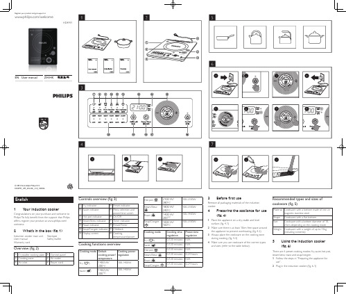
User manual ZH-HK 使用手冊3 T ap the On/Off icon .(fig.6-2)»the On/Off indicator lights up.»The induction cooker beeps.»All indicators light up once and then go off.»The induction cooker stays in standby mode.4 T ap the menu icon repeatedly until the desired cooking mode is selected.(fig.6-3)»The cooking mode indicator lights up and the induction cooker starts heating up thecookware.»The remaining cooking time and cooking power or temperature are displayed on the screen insequence.5 When the cooking is finished,tap the On/Off iconto stop the cooking process,and the induction cooker switches to standby mode.6 Unplug the induction cooker after the fan stops working.(fig.6-4)Using the timerThe induction cooker provides you with flexible control over the cooking time you want the appliance to operate in different cooking modes.1 Follow the steps in “Preparing the appliance for use”.2 Plug in the induction cooker.(fig.6-1)3 T ap the On/Off icon .(fig.6-2)4 T ap the menu icon repeatedly until the desired cooking mode is selected.(fig.6-3)5 T ap the Preset/Timer icon until the timer indicator lights up.(fig.6-6)6 Slide your finger clockwise on the circular Power/ Time switch area to increase the cooking timeby 5 minutes;slide anti-clockwise to decrease the cooking time by 5 minutes (fig.6-5).Y ou can also tap the increase or decrease icon to adjust the cooking time by the increment of 1 minute. (fig.6-7)7 When the cooking time has elapsed,the induction cooker beeps and turns off automatically.Note•After you have selected the cooking time,waitfor a few seconds before the induction cookerautomatically confirms it.Preset time for delayed cookingWith the preset funtion,you can set the time at which you want the appliance to start cooking in steam/stew and soup.congee modes.1 Follow the steps in “Preparing the appliance for use”.2 Plug in the induction cooker.(fig.6-1)3 T ap the On/Off icon .(fig.6-2)4 T ap the menu icon repeatedly until the desired cooking mode is selected.(fig.6-3)5 T ap the Preset/Timer icon until the preset indicator lights up.(fig.6-8)6 Slide your finger clockwise on the circular Power/ Time switch area to increase the preset time by 20 minutes;slide anti-clockwise to decrease the preset time by 20 minutes (fig.6-5).Y ou can also tapthe increase or decrease icon to adjust the preset time by the increment of 1 minute.(fig.6-7) 7 When the preset time has elapsed,the induction cooker beeps and starts working automatically.Note•After you have selected the preset time,waitfor a few seconds before the induction cookerautomatically confirms it.Setting up child lock• When the induction cooker is switched on,longtap the childlock icon for 3 seconds to activatechildlock.• T o deactivate childlock,long tap the child lock iconfor 3 seconds again.Note•When childlock is activated,only Childlock andOn/Off are responsive.6 Cleaning (fig. 7)1 Unplug the appliance and let it cool down.2 Clean the appliance with a damp cloth (fig.7-1)and,if necessary,with some mild cleaning agent(fig.7-2).3 Clean the air outlets with a brush.(fig.7-3)7 EnvironmentDo not throw away the appliance with thenormal household waste at the end of its life,but hand it in at an official collection point forrecycling.By doing this,you help to preservethe environment.8 Guarantee and serviceIf you need service or information or if you havea problem,please visit the Philips website at www. or contact the Philips Consumer CareCentre in your country (you will find its phonenumber in the worldwide guarantee leaflet).If there isno Consumer Care Centre in your country,go to yourlocal Philips dealer.9 T roubleshootingIf your induction cooker does not function properlyor if the cooking quality is insufficient,consult the tablebelow.If you are unable to solve the problem,contacta Philips service centre or the Consumer Care Centrein your country.Problem SolutionThe On/Off icondoes notrespondThere is a connection problem.Check if the induction cooker isconnected to the mains and ifthe plug is inserted firmly intothe wall socketWhen I tapthe menu icon,the light of theselected modedoes not go on.The light is defective.T ake theappliance to your Philips dealeror a service centre authorisedby Philips.E5 or E6 isdisplayed on thescreenCheck if the voltage is too lowor too high.Check if the power cord orpower socket is too hot.Check if too many appliances areplugged to the same connector.E0,E1,E2,E3,E4,E8 or E9 isdisplayed on thescreen.The induction cooker hasmalfunctions.T ake the applianceto a Philips dealer or a servicecentre authorised by Philips.The inductioncooker stopsworking or turnsoff automatically.The induction cooker has beenidle for more than 2 hours.Check if the air inlet and outletsare covered.T emperature around theinduction cooker is too high.繁體中文1 您的電磁爐恭喜你購買 Philips 產品,歡迎來到 Philips 世界!要享受 Philips 為您提供的全面支援,請在以下網站 /welcome 註冊您的產品。
- 1、下载文档前请自行甄别文档内容的完整性,平台不提供额外的编辑、内容补充、找答案等附加服务。
- 2、"仅部分预览"的文档,不可在线预览部分如存在完整性等问题,可反馈申请退款(可完整预览的文档不适用该条件!)。
- 3、如文档侵犯您的权益,请联系客服反馈,我们会尽快为您处理(人工客服工作时间:9:00-18:30)。
HK110 Maintenance Manual HISENSE INTELLIGENT COMMERCIAL SYSTEM CO. ,LTD.1. Product Appearance201.7mm293.7mm426.5mm2. Maintenance process1.HDD removeRemove the screwPull out the HDD holder in the direction of the arrow below, and then remove the cables.Remove the 4 screws2. Inside of host maintenance Remove the 3 screwsSlowly lift up the operating display part by about 20°angle in the direction of the arrow below and then remove the whole operating display part and put it on the front cover of keyboard .Note: Please put some cushion material under the operating display in advance for protecting it from scratching.Screws3. Customer display removeRemove the 4 screws from customer display hold; detach the cable of customer display.Remove the 4 screws.Cable of customer display4. Operating display and touch screen removeFirst you need to detach the 4 cables, including the touch screen cable, indicator light cable, LVDS cable and the inverter cable.Before you remove the LVDS cable, you need to remove 4 screws (highlighted in red square as shown below) for operating display holder, and then remove the operating display with holder. Note :1. Please loosen the snap of the operating display slightly2. Please keep the screws and cables well.Remove the four screws, separate the holder from the panel.5. Motherboard removeRemove the four screws and all the cable of the motherboard side to separate the motherboard from host housing.Touch screen cableinverter cablesnap of operating displayEarth cable of customer display6.Remove the 3 screws of the front coverSlightly lift up the front cover of the keyboard in the direction of arrow below, and separate the front cover of keyboard from the host housing part.Keyboard, MSR, lock of keyboard, FID module7. Printer removeLoosen the two screws and take the printer out of the host housing, remove the cables8. Motherboard MaintenanceCable introduceInverter cable Power cable of printerLVDS cableI/O interfaceMotherboard Pin DefinitionConnectors & FunctionsC onnector F unction1.ATXPWR +12V DC output port2.SODIMM DDR3 SO-DIMM3.JCMOS CMOS operation mode4.CPU_FAN CPU FAN5.JP1 LVDS power setting6.LVDS LVDS connector7.IVCN I nverter connector8.J3 PS/2 keyboard port pin header9.JP2 +24V DC input for cash drawer10.JVGA VGA connector11.MINIPCIE M ini-PCIE connector12.F_AUDIO A udio line out13.INTSPK S peaker port pin header14.JC3 COM3 RI setting15.JC4 COM4 RI setting3COM3 port pin header5COM5 port pin header4COM4 port pin header2COM2 port pin header6 COM6 port pin header21.JUSB1 USB port pin header22.JUSB2USB port pin header23.SYS_FAN SYS FAN24.SATAPWR SATA POWER connector25.F_PANEL F ront panel pin header26.SATA SATA connector27battery battery(1)Commonly Jumper DescriptionJumper Pin F unction SettingJCMOS 3-pin Clear CMOS 1-2 Normal2-3 Clear CMOSJC3、JC4 6-pin Setting COM3,COM4Voltage1-2 12V3-4 5V5-6 RIF_PANEL 9-pin HDD LED、Power LED、Switch reset、ATX interface1-3 Power button2-4 HDD LED5-7 Reset6-10 Power LEDJP2 5-pin Cash drawer power JP2 connect ATX power:24V; disconnect ATX power:12V(2)DisplayDisplay Description Display chips Intel GMA3150InterfaceVGA DB15LVDS 2*20PinDisplay ModeDualdisplaySupport Colon and extended displaySupport Mode Support for CRT resolutions up to QXGASupport for dual-channel LVDS resolutions up to UXGAI nterface defined 2*20 PIN LVDS CONNECTORPIN Defined:Pin S ignal Pin S ignal1 VCC2 VCC3 GND4 GND5 VCC6 VCC7 LVDS0_N08 NC9 LVDS0_P010 NC11 GND 12 GND13 LVDS0_N114 NC15 LVDS0_P116 NC17 GND 18 GND19 LVDS0_N220 NC21 LVDS0_P222 NC23 GND 24 GND25 LVDS0_CLKN26 NC27 LVDS0_CLKP28 NC29 GND 30 GND31 L VDS_DDCPCLK32 L VDS_DDCPDATA33 GND 34 GND35 LVDS0_N336 NC37 LVDS0_P338 NC39 NC 40 LVDS_VCON Support single-channel 24Bit outputI nverter interface defined IVCN1 12V2 GND3 BACKLIGHT_EN4 BKLT PWM5 5VLVDS Voltage select able Pin JP1Pin Define1-2(default) 3.3V2-3 5VNote Support 10.4;12;15-inch panel (3)USBUSB DescriptionType USB2.0 interfaceRear 4Front PinJUSB2 PIN :1 VCC:Power2 VCC:Power3 D-:Data-Signal4 D-:Data-Signal5 D+:Data+Signal6 D+:Data+Signal7 GND 8 GND9 KEY 10 NCPin Type 2*5Pin header/2.54mm(4)F-AUDIOAudio DescriptionAudio Codec Realtek ALC662Rear IO Type Line out, MIC inOnboard audio pinPIN Defined1 MIC-L2 GND3 MIC-R4 VCC3.3V5 NC6 NC7 FRONT-SENSE 8 Key9 NC 10 NCPin Type 2.54mm 2*5pin header(5)INTSPKAmplifieroutputDescriptionType 2W4INTSPK Pin Defined 4Pin 2.0MM:1 R-2 R+3 L+4 L-(6)PS/2PS/2 DescriptionType 1个PS/2 standard interface electrical specification:5V ,1A;J3 Pin Defined K/BPin2X4Pin 2.0MM1 +5V_PS2 2 +5V_PS23 KCLK4 KCLK5 KDAT6 KDAT7 GND 8 GND(7) JP2Cash Drawer DescriptionType 24V Cash drawer electrical specification :24V ,1A;JP2 Pin Defined 5Pin 2.540MM1 24V2 NC3 NC4 GND5 GND(8)COMCOM DescriptionCOM function COM3、COM4 support for 9Pin 5V/12V jumper selectable COM position COM1: standard DB9Male,2x5pin 2.54mmCOM Pin Defined COM Pin :1 DCD2 RXD3 TXD4 RTD5 GND6 DSR7 RTS 8 CTS9 RI 10 NCType DB9 Male, 2*5pin(9)JVGAVGA DescriptionType VGA PinPin Defined 2X5Pin 2.0MMJVGA1 GND2 VCC3 RED4 HSYNC5 GREEN6 VSYNC7 BLUE 8 DDC_CLK9 GND 10 DDC_DATA(10)JUSB1USB Description Type USB waferPin Defined 4Pin 2.0MM wafer Pin DefinedJUSB11 VCC2 DATA-3 DATA+4 GND(11) SATA PowerSATA Power DescriptionType SATA PowerSATAPWR1 4Pin 2.54MM1 12V2 GND3 GND4 5V(12) CPU_FANFAN pin DescriptionType CPU_FANFAN 1X3Pin 2.54MMCPU_FAN;SYS_FAN1 GND2 12V3 C ontrolSuper IO Information (BIOS default)COM1:3F8/IRQ4;COM2:2F8/IRQ3;COM3:3E8/IRQ5;COM4:2E8/IRQ7;COM5:2E0/IRQ10;COM6:2E0/IRQ11;LPT:378/IRQ6;Parallel Port Mode: SPP(default)(EPP/ECP/EPP+ECP option)3. Other function boards introduceInverterboardTouch screen control boardSwitch indicatorboardFront back4. POS common problems & solutions ·Touch screen troubleshootingPossible Causes SolutionsDriver is not installed or installed incorrectly version;Install the correct driver according to the CD; Touch screen cable is damaged or incorrectly connected;The correct connection is shown in the picture below; If the connection is correct but the touch screen is still not working, you should replace the touch screen cable;Touch screen control board does not work; Please replace the touch screen control board; Touch screen or motherboard does not work;Please replace the touch screen or motherboard;•Operating display troubleshootingPossible Causes Solutions Defaulted BIOS settings of operation display is not correct; The correct defaulted BIOS settings of Operating display is 800*600,18bit ,output mode is CRT+LFP; The operating display cable is damaged;Please replace the Operating Display cable;The operating Display is damaged; Please replace the Operating display; The motherboard hardware is damaged (LVDSsection);Please replace the motherboard;Customer display troubleshootingPossible causesSolutionsThe cable of customer display is not connected well;Please make the cable be connected well; The customer display module does not work; Please replace the customer display module;The port to customer display is not COM3; The COM3 correct position is shown in the picture below;The pin jumper position is not correct;The correct pin jumper position is shown in the picture below;•Printer troubleshootingPossible causes SolutionsThe signal cable and power cable are not connectedPlease make the cable be connected well;well;Printer module does not work; Please replace the printer module;Printing paper is abnormal; Please replace the thermal paper or install thermal papercorrectly once againIt is paper jam or paper out;The port to printer is not COM2; The COM2 correct position is shown in the picture below;Note: If the printer cannot print normally or some unreadable code are printing, please c heck if th e baud rate setting is matched? If not matched, please set the suitable baud rate by software “Settings tool v2.05”.Self-checking method: First turn off the printer, secondlypress down the feed button and the power button together,if the buzzer is ringing and the power light is on, that means the operation is normal and then you can release the power button and the FEED button.Back of printerKeyboard and MSR troubleshootingPossible causes SolutionsThe cables of keyboard and MSR are notPlease make the cable be connected well; connected well;The keyboard does not work; Please replace the keyboard moduleThe MSR does not work; Please replace the MSR module。