pro22in instal
ATN PS22 夜视设备说明书

DAY/NIGHT SYSTEMRepresenting the latest advancement in Night Vision optics, the ATNPS22 gives your daytime scope Night Vision capability in a matter ofseconds.The ATN PS22 mounts in front of a daytime scope to enable nighttimeoperation. No shift of impact, no need to rezero nor change of eyerelief occurs. The ATN PS22 uses the latest in image intensifier tubetechnology for outstanding resolution and performance.Precision optical alignment is essential for a front sight system to workproperly. This is why each ATN PS22 is individually tested and alignedon an optical scale by our engineers to provide perfect alignment.The ATN PS22 is one of the most compact and lightweight NV systemsin its class, at only 600 grams.Easily changes daytime scope to Night VisionMounts in front of daytime scope, no re-zeroing requiredMulti-coated all-glass opticsFast catadioptic front lens systemLarge 21 mm eyepiece/output windowLightweight and ruggedComes with Quick Release MountOptional 7/8” weaver mountOptional Scope Mounting System for coupling to the objective ofthe day scope (25...62 mm diameter)Automatic Brightness ControlResistance to severe conditionsUp to 60 hours of continuous operation with one Lithium battery1 IR illuminator IR4502 Picatinny Rail3 Shipping/Storage Case4 Operator’s Manual5 Remote Control6 Two Lithium Battery CR123A7 Quick Release Mount8 Back Cap9 Front Lens Cap10 PS22 Night Vision Front Sight11 Light Supressor for the scopes with42-63 mm lens diameter12 Light Supressor for the scopes with30-42 mm lens diameter13 Light Supressor for Trijicon ACOG scopesExport Warning: These products are subject to one or more of the export control laws and regulations of the U.S. Government. Pending the model these products are under the control jurisdiction ofeither the US Department of State or the US Bureau of Industry and Security US Department of Commerce. Export without proper licensing or consent is strictly prohibited.PS22 WITH TRIJICON® ACOGPS22 WITH LEUPOLDPS22 WITHLEUPOLD® MARK 4 2.5-8X36MMPS22 WITHLEUPOLD® MARK 4 CQ/TBASIC KIT INCLUDES12345678910111213PS22-2I。
掌握的安全感:Simpson Hybrid Pro helmet说明书

INSTALLATION MANUAL INSTAL NSTALLATION MANUALDRIVEN BY SAFETY 3proCER INTAK TAKING IMPACTSANDMUTIE PLATES Simpson Hybrid Head Restraints are the bestchoice for racing protection.HYBRID, HYBRID PRO and HYBRID SPORTHead Restraints are SFI 38.1 Certifi ed and FIA 8858-2010 Certifi ed. Designedfor easily exiting the car without the danger of getting hung upon other gear, our Head Restraints also offer the lowest profi le and highestlevel of multiple angle impact protection of any competing device. Plus, they provide you with maximum comfort and maneuverability. Expertly engineered by Trevor Ashline with Safety Solutions technology,Simpson Head Restraints give you everyadvantage on the track.OF COURSE, IT’S THE SAFEST.IT’S A SIMPSON.Overview3Anchor Installation 4Fitting the Restraint 7Seat Positions7In Car Adjustments Tether Adjustment8Side Stabilizing Gusset Adjustment 10Seat Belt Positioning11 Restraint System Mounting Zones 11Optional AccessoriesSeat belt Anchor Systems (SAS) 12Hybrid Molded Pad13 Helmet Tethers and Clips 14 Helmet Anchors15Frequently Asked Questions 16Certifi cations 19DUAL END FITTINGSRUBBER SHOULDERSSHOULDER STRAPBACK STRAP3-BARSLIDING TETHERQUICK RELEASE(STANDARD on SFI CERTIFIED RESTRAINTS)BUCKLEDEVICE PADSIMPSON HEAD RESTRAINTYou’re ready to use the technology that protects the world’s top drivers. Here are the steps to get started.Questions? Call us at 800.654.7223Hybrid Pro pictured with optional M6 upgradeFigure 1The Simpson Hybrid head restraints series carries SFI 38.1 certifi cation; the Hybrid and Hybrid Pro are NASCAR certifi ed, the Hybrid, Hybrid Pro, and Hybrid Sport are FIA Approved. Our head restraints are recognized by most major sanctioning bodies across the world. If you are unsure, check with your local sanctioning.CERINTAKTAKING IMPACTSANDMUANCHOR INSTALLATIONhorizontal line. The center line of the helmet is midway between where the twolines intersect the horizontal line at the back of the helmet.Measure 6” (150mm) forward from the rear center line on each side of thehelmet to a point 1.5” (43mm) above the rubber molding.Make sure you have two marks, each 6” forward from the rear center line a 1.5”Gently pry helmet away from shell using blunt instrument.123456M6 AND POST ANCHORSQUICK RELEASE ANCHORS12CER INTAK TAKING IMPACTSANDMUTo adjust the chest strap: loosen the chest strap at the buckle and slide the buckle to fi tthe occupant’s chest size. Chest strap should fi t snug, but comfortable.You may have purchased one of the newest helmets marked Snell SAH2010. These helmets are certifi ed for head restraint system use.Helmets marked Snell SAH2010 have a bonded-in and threadedterminal (nutwasher) making Simpson anchor installation easy. Screw the anchor into the nutwasher. Hand tighten until the point on the collar (if post anchor) or bail (if quick release) faces rearward. Tighten the mounting screw 1/4 turn beyond snug.ANCHOR INSTALLATION INSTRUCTIONSSAH2010 Helmets with Bonded-in Threaded Anchor TerminalsSnell SAH2010 decal located inside the helmetBonded-in terminal on sides of helmetSAFETY NOTE Simpson recommends using thread locking fl uid when assembling the M6 and helmet post anchors.FITTING THE RESTRAINTSEAT POSITIONSThe Hybrid Head Restraint has an adjustable chest strap to fi t a variety of body types. Custom made re-straints are also available. Call Team Simpson at 800-654-7223 for more information.STRAIGHTA completely smooth or fl atback to the seat.Typical applications are:Sprint Cars, Pro Mods, Pro Stock, Top Sportsman, Monster TruckCONTOUREDA 10-30 degree of change in the seat at the shoulder blade area.Typical applications are:Late Models, GT -1, Pro Trucks, HydroplanesLAYBACKA 30 degree of more change in the seat at the shoulder blade area.Typical applications are:Indy Cars, Nostalgia Dragsters0°-10°10°- 30°30°+Figure 9Figure 10Figure 11Figure 12NOTE: Changing seat confi gurations may require tether adjustments.CER INTAK TAKING IMPACTSANDMUGet into car and buckle fully into the seat with seat belts. The head restraint should fi t comfortably under the shoulder harnesses.Seat the restraint against the shoulder belts by pulling up on the helmet tethers, before they are hooked to the helmet. The device will rest against the shoulder belts on the top, the seat in back and the driver’s shoulders.The helmet tethers should be adjusted or changed to allow for no more than 2.25” of straight forward head movement. Measure from a resting position(See Figure 13 dotted line) moving your entire head forward (not your chin toyour chest). You should still be able to rotate your chin to your chest.Adjust the rear helmet tether fi rst; they are the PRIMARY RESTRAINT The tethers are easily adjusted by unlacing the tether webbing through the 3-bar adjuster and lengthening or shortening the tethers through the 3-bar adjustments.The forward helmet movement can be checked by measuring the amount of forward movement as the driver moves their head straight forward, with the chin up.The tether adjustment is the measurement when the tethers fi rst have tension.When the rear tether adjustments are complete make sure to lock down the tether by weaving the webbing back through the adjuster one last time. Use the rubber O-ring to hold the excess webbing in place.IN CAR HELMET TETHER ADJUSTMENTRESTRAINT TETHERSADJUSTABLE (SFI) TETHRS1234567Figure 13no more than 2.25” of straightforward movementHelmet Tethers MUST be adjusted for proper fi t before use.Helmet tether adjustment needs to be made with the driver seated and buckled into the vehicle with full gearincluding, suit, helmet, and seatbelt harnesses.CER INTAK TAKING IMPACTSANDMU The shoulder belts should be mounted as close to the occupant as possible, separated by 2-3 inches between the inside edges of the belts.RESTRAINT SYSTEM MOUNTING ZONESCRISSCROSSBELT POSITIONSEPARATEDBELT POSITIONRecommended distance between theinside edges of the belts is 2” - 3”.Figure 15Figure 16Figure 17Unhook the tether from the helmet.Hold the SSG up to the Helmet Anchor.Adjust the length of the tether to the bottom of the Helmet Anchor with the driver in their normal position looking straight forward. NOTE: Some drivers may want this tether shortened formore side to side restriction. The tether may be adjusted shorter by as much as 1” depending on driver comfort. With this adjustment too short, the helmet will be pulleddownward on the driver’s head and may beuncomfortable.Tethers adjusted properly should create a “Triangle” in the tetheradjustment. See Figure 14SIDE STABILIZING GUSSET (SSG) ADJUSTMENT Figure 149101112CER INTAK TAKING IMPACTSANDMUThe Hybrid Optional Molded Pad is placedbehind the driver between the seat and the driver’s back and shoulders.The U-Shaped Molded Pad can be cut, and/ortrimmed to fi t driver’s seat. Tape, glue, or Velcrothe molded pad in place depending on type ofseat. If the seat has a cover, the pad can beinstalled under the cover.The Pad is inserted into the seat back. Whenthe driver sits back, the device nests into the voided area creating one smooth surface behindthe driver’s back. The wings of the restraint should extend under the shoulder belts betweenthe seat back and the driver.The SAS straps need to attach to the seat belt buckle; theSAS is an additional load path for the restraint allowing for stabilization of the driver.Camlock Attachment Slide each SAS O-ring onto two ofthe camlock buckle tongues. See Figure 18Latch-in-Link Attachment Pair the SAS O-rings and slide them into the latch link shoulder belts or the fi ve point depending on your set-up. See Figure 19The SAS straps should be adjusted to be snug when the buckle is latched with no more than 2 fi ngers of room. Adjustment is made by sliding the 1” webbing attached to the loops through the 3-bar adjuster.OPTIONAL HYBRID MOLDED PADOPTIONAL SEAT BELT ANCHOR SYSTEM (SAS)OPTIONAL SAS LOOPS AVAILABLEFigure 18Figure 19Figure 20Figure 21Figure 22CER INTAK TAKING IMPACTSANDMUEZ SLIDE DUAL END FITTING TETHERAVAILABLE WITH QUICK RELEASE OPTIONHYBRID POST CLIPSUSED WITH SIMPSON POST ANCHORSM61 DUAL END FITTING TETHERUSED WITH M6 ANCHOR SYSTEMOPTIONAL HELMET TETHERSQUICK RELEASE TETHERSUSED WITH D-RING (STANDARD)HYBRID QUICK CLICK TETHERSEZ SLIDE LOOPSUSED WITH SIMPSON QUICK CLICKSSIMPSON POST ANCHORSQUICK RELEASE ANCHORSOPTIONAL HELMET ANCHORSM6 ANCHORWITH DUAL END FITTINGSIMPSON QUICK CLICK SYSTEMCERINTAKTAKING IMPACTSANDMUVisitQ: My Helmet came pre-drilled, can I use the pre-drilled hole?A: Simpson helmets will be the correct location. If your helmet is not a Simpson check with your helmetmanufacturer to confi rm the location.Q: Do I need special seat belts to work with your devices?A: No, our devices work with 2 or 3 inch seat belts, Latch and Link or Cam Lock.Q: Do I need to replace my head restraint if I am involved in a wreck?A: Your Simpson Head Restraint device is built to sustain the most violent of wrecks. However, in the eventof a hard wreck, you should send your restraint to us for proper inspection by a Simpson Safety Specialist.We may recommend replacing the helmet tethers. While the chances of the device being unharmed are great,it is not worth taking a chance.Q: Can two people of different sizes share the same device?A: Yes, we have a chest extender that will plug into the chest strap to give more length in the chest.Q: Is my device adjusted wrong if I can touch my chin to my chest?A: No, with your device adjusted correctly you should be able to rotate you head enough for your chin totouch your chest.Q: I am having trouble turning my head even after adjustments, what should I do?A: Call you Simpson Safety Specialist; your setup may require an EZ Slide System.Q: When I measure my helmet for the anchors hard foam in the way on the inside, what should I do?A: Very gently use a large fl at screw driver or small pry bar to wedge between the liner and the shell.This liner is not glued into the helmet, but use caution not to compromise the shell or the liner. Thensimply slide the nut washer into place. DO NOT DRILL THROUGH OR COMPROMISE THIS FOAM LINER.Q: I have a Hybrid and it feels like it pushes me forward out of the seat. What can I do?A: You can order the optional molded seat pad that can be cut, trimmed, shaved or ground to bewhatever shape you need to be comfortable.Q: My child is just getting started racing, will I have to purchase another device as they grow?A: Probably not. This will depend on how big they are and how fast they grow. Once the child is at a 28inch chest, the device that they wear will be able to be re-sized to whatever size they need.Q: How often should I replace my head restraint?A: Each Sanctioning body is different. As of 2012 SFI required all SFI 38.1 certifi ed devices to beinspected every 5 years. For additional information on recertifi cation please check out our web site atFAQ S FREQUENTLY ASKED QUESTIONS FREQUENTLY ASKED QUESTIONSFAQ SCERINTAKTAKING IMPACTSANDMUVisitSINCE 1959, SIMPSON PERFORMANCE PRODUCTS has been the leading manufacturer of safety equipment for theMotorsports Industry. We believe in putting safety fi rst and are dedicated to elevating the standards of racing safetythrough continuous development, refi nement and testing as well as a strong partnership with racing sanctioningbodies worldwide. The Hybrid Head Restraints are certifi ed by SFI and FIA.SFI: THE SFI FOUNDATION, INC is a non-profi t organization established to issue and administrate safety standardsfor specialty and performance of automotive and racing equipment. SFI Oversees testing and standards for fi re suits,restraints and many other high performance safety products in the United States. NASCAR and NHRA are among thesanctioning bodies who abide by SFO standards.MORE INFORMATION CAN BE FOUND AT FIA: THE FEDERATION INTERNATIONALE DE L’AUTOMOBILE is a non-profi t organization that brings together227 national motoring and sporting organizations from 132 countries on fi ve continents. FIA Formula One WorldChampionship, FIA World Rally Championship and FIA World Touring Car Championship are among the sanctioningbodies who abide by FIA standards.MORE INFORMATION CAN BE FOUND AT The products and parts shown herein are to be installed and used adjusted in accordance with these instructions. Any deviation by the buyer,installer, or user from these instructions constitutes willful negligence. Products and parts are not to be used if defective, damaged or worn.Products and parts are not to be used after a severe use, in any event.CERTIFICATIONS CERTIFICATIONS DISCLAIMER DISCLAIMERMODEL #SERIAL #Vehicle racing is inherently a dangerous sport with signifi cant risk of person injury or even death. When a user participates in vehicle racing, he accepts the risk inherent therein.Simpson Performance, Inc. makes no warranty that the use of its products or parts guarantees personal safety or freedom from physical injury or operates as a life saving device.SIMPSON PERFORMANCE, INC.’S PRODUCTS AND PARTS ARE SOLD “AS IS” WITHOUT ANY WARRANTY WHATSOEVER. EXPRESS WARRANTIES, IMPLIED WARRANTIES,WARRANTIES OF MERCHANTABILITY AND WARRANTIES OF FITNESS FOR A PARTICULAR PURPOSE ARE EXCLUDED. THE ENTIRE RISK OF QUALITY AND PERFORMANCE OFSUCH PRODUCTS AND PARTS IS WITH THE BUYER, USER SUBSEQUENT USER, OR AGENT THEREOF (HEREIN “USER”). SHOULD SUCH PRODUCTS OR PARTS PROVE DEFECTIVEFOLLOWING THEIR PURCHASE, THE BUYER AND NOT THE MANUFACTURE(S), DISTRIBUTOR(S), OR RETAILER(S), ASSUME THE ENTIRE COST OF ALL NECESSARY SERVICES ORREPAIR.Simpson Performance, Inc. disclaims all liability for any special, direct, incidental or consequential damages, or any damages whatsoever, including, without limitation, the loss oflife or limb, or damages due to bodily or personal injury, which may arise or result from the sale, installation, or use of any of its products and parts.It is the user’s responsibility to inspect and verify the dimensions, specifi cations, and performance of all products and parts as being appropriate for the use to which the user willput them prior to any actual installation and/or use of said products and parts.Simpson Performance, Inc.’s products and parts are to be inspected by the user before each use for evidence of damage, defect, or wear. Any deviation by the user from themanufacturer’s specifi cations concerning use, maintenance, repair, alterations and modifi cations constitutes willful negligence.The installation of Simpson Performance, Inc.’s products or parts may adversely affect other vehicle components, safety equipment or manufactured goods (collectively “goods”).Simpson Performance, Inc. assumes no responsibility for any damage to other goods, or bodily injury that may arise due to failure of other goods, due to installation and/or use,either proper or improper, of its products or parts.The liability of Simpson Performance, Inc. is limited to the replacement of defective products or parts found under examination by manufacturer to be defective in material orworkmanship within 60 days after purchase, and which has not been caused by an accident, improper use, alteration, tampering, excessive use, misuse, modifi cation or abuse.The damage of the user shall be deemed liquidated in the costs of replacement of the product or part.Simpson Performance, Inc. assumes no responsibility for errors, omissions, diagrams, pictures, illustrations or text in these instructions or the documents contained herewith.By purchasing or using this product, the user agrees that if any provision of this Disclaimer is held to be illegal, invalid or unenforceable under present or future law, such provisionshall be fully severed from the Disclaimer and this Disclaimer shall be construed and enforced as if such illegal, invalid or unenforceable provision never comprised a parthereof, and the remaining provisions hereof shall remain in full force and effect and shall not be affected by the illegal, invalid, or unenforceable provision, there shall be addedautomatically as part of this Disclaimer a provision as similar in its terms to such illegal, invalid or unenforceable provision as may be possible and be legal, valid and enforceable.DRIVEN BY SAFETY 20CALL CUSTOMER SERVICE TOLL FREE800.654.7223OR E-MAIL SALES*********************VISITDRIVEN BY SAFETY。
Opto 22 SNAP PAC 学习中心用户指南说明书

SNAP PAC 学习中心用户指南FORM 1638-060615-2006年6月版权﹪©2003-2006 Opto 22.版权所有翻印必究美国印刷本手册信息,经仔细检查确信正确无误。
但是,Opto 22对可能的不准确性、或遗漏不承担责任。
本说明书的任何变更,无须预先书面通知。
Opto 22针对其所有产品免于任何材料或工艺缺陷的担保期限,自制造日期编码上所示日期起为30个月。
本担保,仅限于针对本单元的原始成本,不包括安装、劳动力或任何其他临时成本。
Opto 22 I/O模块和日期编码为1/96或稍后的固态继电器的担保期限为终身。
该终身担保期限,不包括舌簧继电器、SNAP串行通信模块、SNAP PID模块、及包括机械接触或开关的模块。
对非由Opto 22生产的任何产品、组件、或部件,Opto 22将不提供担保;对于这些条目,原始制造商的担保将适用。
这些产品,包括但不限于:OptoTerminal-G70、OptoTerminal-G75、及索尼爱立信GT-48;针对具体的担保信息,请见产品一览表。
有关完整的担保信息,请参见Opto 22 form号码1042。
————————Cyrano、Opto 22FactoryFloor、Optomux、及Pamux为Opto 22的注册商标。
Generation 4、PAC Control、PAC Display、PAC Manager、PAC Project、ioUtilities、mistic、Nvio、Web Portal、OptoConnect、OptoControl、OptoDisplay、OptoENETsniff、OptoOPC Server、OptoScript、OptoServer、OptoTerminal、OptoUtilities、SNAP Ethernet I/O、SNAP I/O、SNAP OEM I/O、SNAP PAC、SNAP Simple I/O、SNAP U ltimate I/O、及SNAP Wireless LANI/O都为Opto 22的商标。
Extron TLP Pro 1022T 安装指南说明书

I M P O R T A NT:m f o rt h el l a t i o n .c oTLP Pro 1022T • Setup GuideOverviewThe TLP Pro 1022T is a 10-inch tabletop capacitive touchscreen with 1024x600 resolution and 18-bit color depth. It offers flexible mounting options and fully customizable interfaces. This guide provides instructions for experienced installers to mount and install a TLP Pro 1022T touchpanel. For complete instructions, see the TLP Pro 1022 Series User Guide, at . Setup ChecklistGet ReadyDownload and install the latest version of the following software:GUI Designer — for designing layouts for Extron TouchLink® Pro touchpanels and third party touch interfaces.Global Configurator® Professional or Global Configurator Plus — for setting up and configuring the control processor and touchpanel.Toolbelt — provides device discovery, device information, firmware updates, and configuration of network settings, system utilities, and user management for TouchLink Pro devices.All three software programs are available from .Obtain the following network information from your network administrator:DHCP status (on or off). If DHCP is off, you must also obtain:IP address Subnet mask GatewayUser name — this can be either admin or user.Password — by default this is extron (for either admin or user).Make a note of the touchpanel MAC address.Mount and Cable All DevicesMount the units. There are several mounting options for TouchLink Pro touchpanels (see Mounting on the following page).Connect the touchpanel to a Power over Ethernet injector.Connect the power injector to the LAN and power it on.Set up the Touchpanels for Network CommunicationConnect the PC that you are using for setup, the control processor, and touchpanel to the same Ethernet subnetwork.Use the Setup Menu (see page 4) or Toolbelt to set the DHCP status and, if necessary, the IP address, subnet mask, gateway, and related settings for the touchpanel.Configure the TouchpanelsThe GUI Designer Help File, the Global Configurator Help File, and the Toolbelt Help File provide step-by-step instructions and more detailed information. The Global Configurator Help File includes an introduction to the software and sections on how to starta project and configuration.1TLP Pro 1022T • Setup Guide (Continued)MountingThe TLP Pro 1022T comes with a stand that allows it to be placed on any suitable flat surface. See for a range of available optional mounting kits. The kits must be purchased separately. Follow the installation instructions provided with the kit.Removing the Base and Back CoversTo attach cables and to mount the TLP Pro 1022T with the SMA-1 or a VESA mounting kit, you must remove the base and back covers:1. Remove the base cover using the provided Extron removal tool.There is a notch at the back edge of the cover (see figure 1, 2).2. When the base cover is removed, a pull tab can be seen (seefigure 2). Use this to remove the back cover.Kensington® Security LockFor added security, attach a Kensington Security Lock (not provided) to the metal-reinforced slot on the rear edge of the base (see figure 1,1). Follow the instructions that are provided by the manufacturer toinstall the lock.Securing the Touchpanel to a Table1. Under the table top, mark the location of two mounting holes,3.07 inches (78 mm) apart (see figure 3, A).2. Drill two holes through the table top from underneath.3. Attach the touchpanel, using two #8 machine screws through thetable top from underneath into the two holes in the base.SMA-1 Swivel Mount AdapterThe TLP Pro 1022T can be mounted with the optional Extron SMA-1 swivel mount adapter, which allows it to be mounted permanently and swivel up to 180° in either direction.1. Remove the base and back covers as described in Removing theBase and Back Covers, above.2. Remove the screw holding the locking plate at the bottom of thebase (see figure 3, B). This releases the weight, which can beremoved from the top of the base, leaving the mounting hole thatwill fit over the conduit of the SMA-1.3. Attach the conduit, insulation disk, and swivel disk and configurethe set screws to allow for the degree of swivel that is required(see the SMA-1 Swivel Mount Adapter Kit User Guide, available at).4. Place the mounting hole in the base over the SMA-1 conduit.5. Secure the unit with the backing plate and locking nut asdescribed in the SMA-1 Swivel Mount Adapter Kit User Guide. VESA Mounting1. Remove the back cover, as described in Removing the Base andBack Covers, above.2. Remove the four screws holding the touchpanel to its base. Thereare two screws in each base attachment hinge (see figure 5, F).3. Use a D-type VESA mounting kit with 75 x 75 mm mountingpattern. Follow the instructions provided with the kit.12Figure 1. Rear of TLP Pro 1022T BasePull Tab(to RemoveBack Cover)Figure 2. TLP Pro 1022T with Base Cover RemovedAB Figure 3. TLP Pro 1022T Base2Front Panel FeaturesFigure 4. TLP Pro 1022T Front PanelA Communication LED — shows the configuration and connection status of the touchpanel:z Unlit during normal operation (the touchpanel is configured and connected to an IP Link Pro control processor).z Blinks red if the touchpanel has been configured but is not connected to an IP Link Pro control processor.z Continuously lit red if the touchpanel has not been configured.The indicator can be toggled between enabled and disabled, using the Setup Menu (see the following page).B Status lights — one LED light bar, above the screen, which can be programmed to provide system feedback.z Light red or greenz Blink or light continuouslyz For information about programming this light, see the Global Configurator Help File.C Light sensor — monitors ambient light level and adjusts screen brightness.D Capacitive touchscreen — 10.1-inch screen with 1024x600 resolution.E Speakers — two speakers, located below the screen, one on each side of the panel, provide audible feedback for the user.F Motion sensor — detects motion between three to five feet in front of the touchpanel, and at least 15° from the center axis.z When no motion has been detected for a user-defined period of time, the touchpanel enters sleep mode.z When motion is detected by the sensor, the screen display is restored and active.Rear Panel FeaturesFigure 5. TLP Pro 1022T Rear Panel A LAN/PoE (Power over Ethernet) ConnectorB VESA Mounting Holes (4)C Menu ButtonD Reset ButtonE Reset LEDF Base Attachment Hinges (2)3468-2405-53 Rev. A04 16Extron Headquarters+1.800.633.9876 (Inside USA/Canada Only)Extron USA - West Extron USA - East +1.714.491.1500 +1.919.850.1000+1.714.491.1517 FAX +1.919.850.1001 FAXExtron Europe+800.3987.6673 (Inside Europe Only)+31.33.453.4040+31.33.453.4050 FAXExtron Asia +65.6383.4400+65.6383.4664 FAX Extron Japan +81.3.3511.7655+81.3.3511.7656 FAX Extron China +86.21.3760.1568+86.21.3760.1566 FAX Extron Middle East +971.4.299.1800+971.4.299.1880 FAX Extron Australia +61.8.8351.2188+61.8.8351.2511 FAXExtron India 1800.3070.3777 (Inside India Only)+91.80.3055.3777+91.80.3055.3737 FAX© 2016 Extron Electronics All rights reserved. All trademarks mentioned are the property of their respective owners. TLP Pro 1022T • Setup Guide (Continued)A LAN/PoE (Power over Ethernet) Connector — is in the top of the recessed area (see figure 5, A on the previouspage). Connect the touchpanel to a PoE power injector (not provided) using a twisted pair cable, terminated with an RJ-45 connector. Connect the power injector to the LAN through a network switch. An Extron IP Link Pro control processor mustalso be connected to the same network as the TouchLink Pro touchpanel.The figure to the right shows the Extron XTP PI 100. Your power injector may look different.B VESA mounting holes (4) — If using VESA mounting, use a D-type VESA mountingkit with 75 x 75 mm mounting pattern (see VESA Mounting on page 2).C Menu button — activates the Setup Menu and calibration screen (see below).D Reset button — Pressing the Reset button allows the unit to be reset in any of three different modes. For full information about the modes, see the TLP Pro 1022 Series User Guide .E Reset LED — provides feedback about the reset status when the user presses the Reset button.F Base attachment hinges (2) — Each hinge secures the touchpanel to the base with two screws.Reset Modes: a Brief SummaryThe TLP Pro 1022T offers the following reset modes:• Use Factory Firmware:Press and hold the Reset button (figure 5, D ) while applying power to the unit. Use this mode with Global Configurator or Toolbelt software to replace firmware in the event of conflicts arising from uploading a firmware update.• Reset All IP Settings:Press and hold the Reset button for 6 seconds. After the Reset LED (figure 5, E ) flashes twice, release and momentarily press the Reset button. Use this mode to reset all network settings without affecting user-loaded files.• Reset to Factory Defaults:Press and hold the Reset button for 9 seconds. After the Reset LED flashes three times, release and momentarily press the Reset button. Use this mode to return the touchpanel to factory default settings.Setup MenuPress the Menu button (see figure 5, C ) to open the setup menu. Select any of the five available screens (Status , Network , Display , Audio , and Advanced ) by pressing the appropriate button in thenavigation bar at the top of the screen (for more information, see the TLP Pro 1022 Series User Guide ).Press and hold the Menu button for at least 3 seconds to open the calibration screen. Follow the on-screen instructions.Figure 6. Setup Menu: Status Screen for TLP Pro 1022TTo network switch To touchpanel。
XP-Pen Artist 22R Pro用户指南说明书

User ManualArtist22R Pro℃℃Contents I.Product OverviewOverviewII.Connecting the Artist22R ProIII.Driver InstallationWindowsMacIV.Driver Settings UIWindowsMacV.Driver UninstallWindowsMacVI.FAQThank you for purchasing the XP-Pen Artist22R Pro.Our product user manual currently supports English,Russian,Japanese,German,Korean,Chinese,Italian,Spanish,and French.We apologize if your preferred language is not supported.{I.Product Overview}OverviewImage1-1.Overview1.Power button(Press and hold for about3seconds to turn on.)a.On,Blue:The Artist22R Pro is connected to your computer and powered on.b.On,Orange:The Artist22R Pro is powered on,but not connected to a computer.c.Off:The Artist22R Pro is powered off.2.Menu button3.+button4.–button5.VGA auto adjustment button6.Display/Working area7.Express key8.Roller keyB portB port11.HDMI port12.VGA port13.Type-C port14.Power jack15.Stand adjustment lever{II.Connecting the Artist22R Pro}You can use the below methods to connect your Artist22R Pro to your computer.a.Connect the Artist22R Pro to your computer and wall outlet via included Type-C cable,power adapter,and power cord.Image2-1.Type-C connectionb.Connect the Artist22R Pro to your computer and wall outlet via the included HDMI,“Type-Cto USB cable”,power adapter,and power cord.Image2-2.HDMI connectionc.Only for the Artist22R Pro:Connect the Artist22R Pro to your computer and wall outlet via the includedVGA,“Type-C to USB cable”,power adapter,and power cord.Image2-3.VGA connectionNotes:a.You must connect the Artist22R Pro’s Type-C port to your computer.The top2USB ports can connect to other USB devices like flash,keyboard,etc.,b.If your computer is a desktop,please connect the Artist22R Pro HDMI cable into the same video card as your general monitor.{III.Driver Installation}Supported operating systems:Windows10,8or7Mac OS X10.10or aboveNotes:(1).Disable any antivirus or firewall software and close any non-essential background software beforebeginning the installation.Some software,such as OneDrive and Dropbox,may monopolize important files and prevent a successful installation.On Windows computers,check the system tray on thebottom-right of the screen and close any software unrelated to your computer hardware.(2).Uninstall any existing tablet software before attempting to install the Artist22R Pro driver.Other tabletdrivers may conflict with the Artist22R Pro driver or prevent installation entirely.(3).Visit the XP-Pen official website and then download and install the latest driver for your tablet.When thedownload is complete,be sure to extract the“.zip”file contents before running“.exe”or“.pkg.”(4).The Artist22R Pro resolution size is1920x1080(max).Windows:(1).Plug the Type-C and HDMI or VGA cables into your computer’s Type-C,HDMI,VGA or USB ports first,then connect the power adapter and power cord into your Artist22R Pro and wall outlet.(2).Download the latest driver version from the XP-Pen website()and be sure to extractthe“.zip”file contents onto your desktop before running“.exe”.(3).After installation,the driver’s icon()will appear in your system tray.If the icon is not present,uninstall the driver,reboot,and repeat step2.(4).Right click your desktop and choose“Display Settings”.Then set monitors“Size to text,apps,etc.”to100%.Image3-1.Display setting(5).On the display setting,you can set your monitors to“Extend these displays”or“Duplicate thesedisplays”.(6).In Extend mode,set your Artist22R Pro to Monitor2and choose a resolution of1920x1080.(7).In Duplicate mode,set both of your monitors to the same resolution.Image3-2.Extend these displays(8).Click“OK”to exit.(9).Double-click the tablet driver’s system tray icon to open your tablet settings.Set your Artist22R Pro’s“Current Screen”to Monitor1or2,then apply and exit.Image3-3.Current ScreenMac(1).Plug the Type-C,HDMI or VGA cables into your computer Type-C,HDMI,VGA or USB ports first thenconnect power adapter and power cord into your Artist22R Pro and wall outlet.(2).Download the latest driver version from the XP-Pen website()and extract the“.zip”file contents onto your desktop before running“.pkg”.Image3-4.Driver(3).Follow the on-screen instructions until installation is complete.(4).Open“System preferences”–“Display”and then set Resolutions to“Default for display”.Image3-5.DisplayImage3-6.Arrangement(5)In the Arrangement tab,you may choose to Mirror Displays.With Mirror Displays enabled,bothmonitors’resolutions should be the same.(5.1)Open“Finder”–“Applications”–“PenTablet”–“Pen Tablet Setting”.(5.2)In the Monitor tab,set Monitor Mapping to iMac/Color LCD.(6)With Mirror Displays disabled,set your Artist22R Pro’s resolution to1920x1080.(6.1)Open“Finder”–“Applications”–“PenTablet”–“Pen Tablet Setting”.(6.2)In the monitor tab,set Monitor Mapping to Artist22R Pro.Image3-7.Monitor{IV.Driver Settings UI}WindowsDouble-click the driver’s icon()in the system tray.Driver UIImage4-1.UI1.1.Pen Function SettingsYou may customize the functions of your tablet pen’s barrel buttons e the“Function Key”option to program custom keystrokes.Image4-2.Pen Functions SettingNote:Pen/Eraser ToggleWith the stylus in range of the Artist22R Pro’s working area,press the assigned barrel button to toggle between pen and eraser modes in compatible drawing software.The current mode will be displayed briefly on your monitor.1.2.Click Sensitivity&Current Pen PressureYou can adjust pen pressure to“Output”or“Press”sensitivity on here.Current Pen Pressure shows the current pressure level being exerted on your tablet and can be used to test pen pressure.Image4-3.Click Sensitivity&Current Pen Pressure1.3.Mouse ModeAbsolute(Pen)Mode:Standard tablet mode;Each point of the tablet’s work area corresponds to an absolute point on your computer display.Relative(Mouse)Mode:Mouse mode;The tablet’s work area does not correspond to absolute points on your computer display and your pen works as a standard mouse.Note:Artist22R Pro is a graphic tablet monitor so please set it to Absolute mode to avoid stylus and cursor offset issue.Image4-4.Mouse Mode1.4.Current ScreenThe Artist22R Pro may be configured for use with single or dual monitors.Generally,this should be set to“Monitor1”or Monitor2.”Image4-5.Current Screen1.5.Import&Export ProfilesImage4-6.Export&ImportYou can use the Import&Export Profile function to save/load your barrel buttons and shortcut keys setting. Note:When you finish setting up your barrel buttons and shortcut keys,click the OK button to save and exit the tablet settings menu.Open tablet setting again and click Export Configuration.Image4-7.Export ProfileImage4-8.Import Profile1.6.Windows InkThis capability can be toggled on and off here.Enabling this will allow support for Windows Ink and applications that run using Windows Ink.Image4-9.Windows Ink1.7.CalibrationThe Calibration tab allows you to set up calibration for your tablet.Image4-10.Calibration1.8.Display Settinga.Color Temperature:Use to adjust the Artist22R Pro’s color balance.er:Use to adjust red,green,and blue color levels on the Artist22R Pro’s display.Brightness andcontrast can also be adjusted here.c.Rotate:You may rotate the Artist22R Pro’s display in this tab.Image4-11.Display SettingNote:a.When you set the rotate function,you must also rotate your Artist22R Pro.b.You must set the Artist22R Pro to Extend These Displays first,after which you can change the rotation.1.9.Express Keys SettingNotes:a.The Artist22R Pro’s shortcut keys are designed to work with US English keyboards.Keys may not function correctly with the other keyboard languages.b.By default,the Artist22R Pro express keys are mapped to standard Photoshop keyboard shortcuts.Keys can be customized to function efficiently in other software.c.You must set one express key from the Switch function to switch dial.Image4-12.KeyboardDisable express keys:When you enable it,all of the express key functions will be disabled.Hide hints:When you enable it and press any express key,the message will not popup on the bottom of your screen.Image4-13.KeysYou may edit the functions of the Artist22R Pro’s shortcut e the“Definition”option to program custom keystrokes.Image4-14.Function KeyNote:Find Detail Mode allow your Artist22R Pro work area to focus on the small size scope to do detail drawing& editing.You can set each shortcut key for different software.a.Click the“+”button to go to Select Program tab.Image4-15.Select Programb.You can choose Default or use Browse to select your choice of software.Image4-16.Select Programc.Return to the shortcut key settings tab,click the tablet icon,and then customize the shortcut keys.When you are finished,click the OK button and exit the tablet settings menu.You can set each Dial1&2for different software.a.Click software icon first then go to Dial1&2tab.Image4-17.Dialb.Click each dial function to“Function key”.c.On the setting tab,you can customize“KL”and“KR”to different shortcuts like Ctrl+&Ctrl-.Image4-18.Setting1.0.DefaultYou can click the Default button to restore default settings.1.11.XP-Pen LogoClick our logo to visit our website.Image4-19.XP-Pen logoMacTo open the Artist22R Pro’s driver settings,open Finder-Applications-PenTabletSetting.Image4-20.Tablet Setting1.1.PenImage4-21.Mac UIa.In this tab,you may customize the functions of your stylus’barrel buttons,adjust pressure sensitivity,and test your pen pressure.b.Click“Default Button Setting”to revert to manufacturer settings.Image4-22.PenNote:Pen/Eraser ToggleWith the stylus in range of the Artist22R Pro’s working area,press the assigned barrel button to toggle between pen and eraser modes in compatible drawing software.The current mode will briefly be displayed on your monitor.c.Disable pen pressure:When the“Disable pen pressure”function is enabled,you can disable the penpressure function.d.Disable Key Function:When you enable it,all of the express keys function will be disabled.e.Disable Display Message:When you enable it and press any express key,the message will not popupon the bottom of your screen.Image4-23.Configuration Settingf.Output:You can adjust pen pressure to“Output”or“Press”sensitivity on here.It shows the current pressure level being exerted on your tablet and can be used to test pen pressure.Image4-24.Outputg.Import&Export Profiles:You can use the Import&Export Profile function to save/load your barrelbuttons and shortcut keys setting.Image4-25.Import&Export ProfilesImage4-26.Export configuration fileImage4-27.Import configuration file1.2.MonitorThe“Monitor”tab allows you to configure your Artist22R Pro to monitor1or monitor2.Image4-28.Monitor1.3.Express KeysNotes:a.The Artist22R Pro’s shortcut keys are designed to work with US English keyboards.Keys may not function correctly with the other keyboard languages.b.By default,the Artist22R Pro express keys are mapped to standard Photoshop keyboard shortcuts.Keys can be customized to function efficiently in other software.c.You must set one of the express keys from Switch function to switch dial.Image4-29.Express KeysIn the Express Keys tab,you may choose your preferred functions for the Artist22R Pro’s shortcut e the“Reset Customer Defined”option to program custom keystrokes.Image4-30.Action SettingYou can set each shortcut key for different software.a.Click the“+”button to go to Select Program tab.Image4-31.Select Program b.Your choice of software.Image4-32.Select Programc.Return to the shortcut key settings tab,click the tablet icon then customize the shortcut keys.When you are finished,click the OK button and exit the tablet settings menu.Image4-33.Hot KeyImage4-34.Action SettingYou can set dial1&2for different software.a.Click the software icon first and then go to the Dial tab.Image4-35.Sliderb.Click each dial function.c.On the setting tab,you can customize“Left HotKey”and“Right HotKey”to different shortcuts like Ctrl+& Ctrl-.Image4-36.Slider Setting1.4.CalibrationThe Calibration tab allows you to calibrate your tablet or rotate your display.To calibrate,click Calibration and follow the on-screen instructions.Rotate:You may rotate the Artist22R Pro’s display in this tab.Image4-37.Calibration1.5.AboutThis tab displays the current version of your driver software.Image4-38.About{V.Driver Uninstall}WindowsIn the Start menu,open[Settings]→[Apps&features].Find“Pentablet”and click“Uninstall.”Follow the on-screen instructions.MacOpen[Finder]→[Application]→[Pen Tablet],then click“Uninstall Pen Tablet”and follow the on-screen instructions.Image5-1.Mac uninstallNote:When attempting to reinstall the Artist22R Pro driver,be sure to reboot your computer after the uninstall is complete.{VI.FAQ}1.Where can I download the latest Artist22R Pro driver?Latest driver releases can be downloaded from our website().2.I can’t use the stylus to control the cursor.a.Turn on your Artist22R Pro and make sure you can see the display.b.Reinstall the driver and then find the tablet icon in the system tray.c.Open it and test the pen pressure gauge insided.If you can’t test the pen pressure,please uninstall the driver and reboot.Make sure your computerlogin account has Administrator authority.e.The Artist22R Pro supports plug and play,please test your stylus function before reinstalling the driver.If you have control,please disable your antivirus then go to the XP-Pen website to download the latest driver.f.When the download is complete,please unzip and extract the contents of the folder to run the.exeor.pkg installation file.g.Open the tablet setting again then make sure can you use the pen pressure on it.3.How do I know that the Artist22R Pro driver installed successfully?a.After installing the driver,the Artist22R Pro Pro’s driver icon should be visible in your system trayon the bottom-right of your screen(Windows OS)and desktop.Pen input will control the cursor and pressure sensitivity will be functional in the driver.4.Why can’t I use the pen pressure on the drawing software?a.Please make sure the drawing software can support pen pressure.b.Make sure you have the latest driver installed.c.Open the tablet setting and make sure you can test the pen pressure in it.d.Enable the“windows ink”function then click the ok button to exit.Open the drawing software againand test your pen pressure.e.Please note our tablets do not come with drawing software.If you have any questions,please contact us at:Web:Email:******************。
KAMVAS PRO 22(2019) GT2201 用户手册说明书
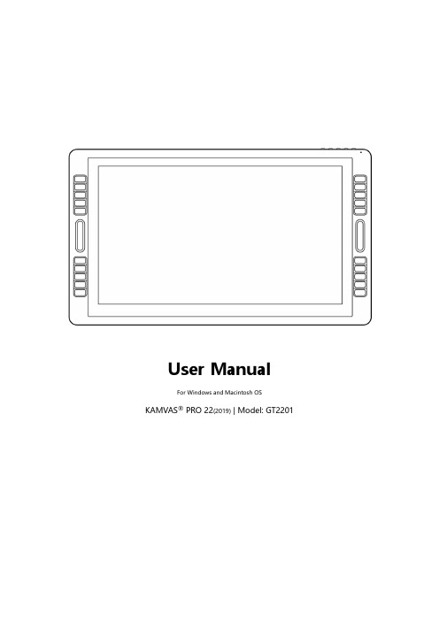
User ManualFor Windows and Macintosh OS KAMVAS® PRO 22(2019) | Model: GT2201Precautions1. Please read this manual carefully before using, and keep it well for future reference.2. Before cleaning the display please unplug the USB cable and wipe with a soft damp cloth, do not use any kind of detergents.3. Please don’t place the display near water sources such as bathtub, washbasin, sinks, washing machine, damp basement, swimming pool, etc.4. Do not place the display on where is unstable or a height for children reaching easily in order to avoid danger.5. Do not place the display and digital pen close to the magnetic field.6. The grooves and holes on the back case is designed for ventilation to prevent the monitor from overheating. Please don’t place the display on beds, sofas, carpets or in embedded device.7. Only power supplies shown on the nameplate can be used for the display. If you have questions about the power supply which you are using, please consult the distributor of your display.8. To protect your display, please switch off the power when it is not in use. During blackouts or not using for long time, please unplug the display from the socket.9. Don’t overload the socket or lengthen the power wire, which may lead to electric shocks.10. Make sure no foreign bodies get inside the monitor through grooves and prevent liquid from splashing on the display as to prevent short-circuit or fire.11. If the display has a breakdown, do not open the main case and try to repair it by yourself. Please ask for a service for proper repair and maintenance.12. When the following situations occur, please unplug the power adapter and you may need a service for full repair and maintenance:A. The power wire or plug is damaged or worn out;B. There is liquid splashed inside of the display;C. The display has fallen or the LCD is broken;D. When obvious abnormalities occur to the display.13. While getting the components replaced, you are supposed to guarantee that the repairman is using the substitute components specified by the manufacturer. Unauthorized component replacement might cause fire, electric shocks or other dangers.Contents1. Product Overview (3)1.1 Display Introduction (3)1.2 Product and Accessories (3)1.3 Setting up Display (4)1.4 Installing the Driver (5)1.5 Pen Nib Replacement (6)2. Product Basic Operation (7)2.1 Using The Pen (7)2.2 OSD Setting (9)3. Function Setting (12)3.1 Device Connection Prompt (12)3.2 Working Area Setting (12)3.3 Press Keys Function Setting (14)3.4 Pen Button Function Setting (15)3.5 Pressure Sensitivity Setting (15)3.6 Pen Pressure Testing (16)3.7 Calibration (16)3.8 Enable the Windows Ink feature (17)3.9 Data Export and Import (17)4. Specifications (18)5. Trouble Shooting (19)5.1 Possible Breakdowns Related to DISPLAY (19)5.2 Possible Breakdowns Related to FUNCTIONS (19)1. Product Overview1.1 Display IntroductionThanks for choosing HUION®KAMVAS®Pro 22 Pen display. This is a new generation of desktop-level professional drawing display, which can greatly improve your work efficiency of painting and creation, and full of fun. You can freely painting and writing, depicting different lines and colors, just as the pen writes on the paper, which brings you a real shock experience.To give you a better understanding and using of your KAMVAS, please read this user manual carefully. The user manual only shows the information under Windows, unless otherwise specified, this information applies to both Windows and Macintosh systems.1.2 Product and Accessories1.2.1 Display Overview1.2.2 Adjustable StandWe designed this ergonomic adjustable stand specially for your KAMVAS display, you can adjust the angle of the display according to your usage habit, and make you feel more comfortable when painting and creating.By dragging this switch to adjustthe stand angle from 20°-80°1.2.3 AccessoriesStylus Pen Pen Holder Pen Nibs Nib ClipUSB Cable HDMI Cable Power Cable Power Adapter Quick Start Guide Warranty Card Glove Cleaning Cloth1.3 Setting up Display1.Take out the pen display and stand from the package, then assemble thestand to the back of the display with attached screwdriver according to thefollowing instruction.2.As shown on the below, connect the pen display to your computer withattached power adapter, HDMI cable and USB Cable.3.Press the power button on the bottom of the display to power on thedisplay1.4 Installing the Driver1.4.1 OS SupportWindows 7 or later,macOS 10.12or later1.4.2Install DriverPlease download the driver from our website: /downloadAfter finishing installation, you can find the driver icon in the system tray area, which means the driver was installed successfully; when you connect the tablet to computer, the icon will change to color , which means the driver has already recognized the tablet and you can start using it now.Notice:1. Before installing, you need to uninstall other driver of similar products, including the old driver of this product.2. Before installing, please close all graphics software and anti-virus software to avoid unnecessary mistake.1.5 Pen Nib ReplacementThe nib will be wear out after using for a long time, then you need to replace a new nib.2. Product Basic Operation2.1 Using The Pen2.1.1 Hold the penHold the pen as you hold a normal pen or pencil. Adjust your grip so that you can toggle the side switch easily with your thumb or forefinger. Be careful not to accidentally press the switch while drawing or positioning with the pen.Notice: When not in use, place the pen in the pen case or on the desk. Do not place the pen on the surface of screen, which may interfere with the use of other screen cursor positioning equipment, it may also cause your computer unable to enter the sleep mode.2.1.2 Position the cursorMove the pen slightly above the active area without touching the screen surface, the cursor will move to the new position accordingly.Press the pen tip on the screen to make a selection. Tap the screen once with the pen tip, or touch it to the screen with enough pressure to register a click.2.1.3 ClickUse the pen tip to tap on the screen once to produce a click. T ap to highlight or select an item on the screen and double-click to open it.2.1.4 MoveSelect the object, then slide the pen tip across the screen to move it.2.1.5 Use the side buttonsThe side buttons of the pen can be set to two different customizable functions. You can use the buttons whenever the pen tip is within 10mm of the display active area.You do not have to touch the pen tip to the display in order to use the switch.2.2 OSD Setting2.2.1 OSD ButtonsPOWER : Power on/off the display.MENU : Press to call up the menu, after entering menu, it’s function is confirm.: After entering menu, it’s function is to up/right/increase.: After entering menu, it’s function is to down/left/decrease.AUTO : Before entering menu, it’s function is auto adjustment. After entering menu, it’s function is back to previous menu.2.2.2 Brightness Setting1.BRIGHTNESS: Adjusting background brightness of the screen images.press the buttons“+”and“-”to increase and decrease brightness.2.CONTRAST:Adjusting difference between darkness and brightness of the screen. Press the buttons“+”and“-”to increase and decrease contrast.3.ECO: There are four eco modes of“STANDARD, TEXT, GAME, MOIVE”.4.DCR: Choosing“on/off”to on/off Dynamic Contrast Ratio.1.H.POSITION: Adjusting images left and right by using thebuttons“+”and“-”.2.V.POSITION: Adjusting images downward and upward by using thebuttons“+”and“-”.3.CLOCK: Adjusting the vertical blinking of characters on the screen.4.PHASE: Adjusting the horizontal blinking of characters on the screen.5.ASPECT: There are“WIDE”and“4:3”two modes for you to adjust the aspect of the screen.2.2.4 Color Temp. SettingCOLOR TEMP.: There are three color modes of “WARM, COOL, USER “.NGUAGE: There are 12 languages for your choice.2.OSD H. POS.: Adjusting the OSD position left and right by using the buttons“+”and“-”3.OSD V. POS.: Adjusting the OSD position downward and upward by using thebuttons“+”and“-”4.OSD TIMER: Increase and decrease the residence time of the OSD menu by usingthe buttons“+”and“-”.5.TRANSPARENCY: Press “MENU”, then“+”and“-”to adjust thetransparency of the OSD menu.2.2.6 Reset1.IMAGE AUTO ADJUST: Automatically adjust the image’s horizontal/verticalposition, focus and clock.2.COLOR AUTO ADJUST: Automatically adjust the image color balance.3.RESET: All the setting options will be restored to the default setting.2.2.7 MISCMISC: Display the current adjustment information.3. Function Setting3.1 Device Connection Prompt1. Device disconnected: The computer does not recognize the tablet.2. Device connected: The computer has recognized the tablet.3.2 Working Area Setting3.2.1 Using Multiple MonitorsWhen the KAMVAS and other monitors are used in the same system, the movement of the screen cursor on the standard display depends on the system configuration.If the secondary display is a mirrored mode connection, KAMVAS and another monitor will display exactly the same image and screen cursor movement.If you are in the extended display mode, you need to set the display on the driver that which portion of the display screen your KAMVAS will map to.3.2.2 Working Area SettingDefine the display area that will be mapped to the screen area.1. Full Area: the entire active area of the Display. This is the default setting.2. Same Ratio with LCD.3. Customized Area: 1.> Enter coordinate values. or2>. Drag the corners of the foreground graphic to select the screen area.3.2.3 Rotate Working AreaBy changing the direction of the tablet to adapt to the left and right hand operation. You can rotate the tablet by 0°,90°,180° or 270°.3.3 Press Keys Function SettingDefault Setting: Place the cursor on the button or click the button icon to see the default values for the press keys.Customized Setting: Select the function to be achieved on the pop-up dialog box, then click APPLY or OK to take effect.(The press keys on the left and right side are the same function, so you just need to set the keys functions on the left side)T ouch Bar: you can slide up and down to achieve zoom function.(Also support Self-customized)Enable/Disable Press Keys: Check/Uncheck”Enable Press key”Enable/Disable Touch Bar: Check/Uncheck”Enable Touch”3.4 Pen Button Function SettingSelect the function to be achieved on the pop-up dialog box, then click APPLY or OK to take effect.3.5 Pressure Sensitivity SettingThe pressure sensitivity will be changed by dragging the slider up and down, the smaller the value, the more sensitive the pressure.3.6 Pen Pressure TestingClick “start pressure test”, you can gradually apply pressure to the stylus on the screen to test the pressure level. Click “Clear” button to clear all the ink.3.7 CalibrationScreen Calibration: Click the red point of the cross center appearing on the screen to complete the calibration.Restore Factory Settings: Click "Restore Default" to restore to the factory settings. Cancel Calibration: Click"Cancel calibration” or press ESC on the keyboard to cancel the calibration.3.8 Enable the Windows Ink featureMicrosoft Windows provides extensive support for pen input. Pen features are supported in such as Microsoft Office、Windows Journal、Adobe Photoshop CC、SketchBook 6 and so on.3.9 Data Export and ImportThe driver supports exporting and importing your customized configuration data of the product, which is convenient for you to use different software and avoid the trouble of repeated settings.4. SpecificationsModel GT2201ScreenPanel Size 21.5 inch Resolution 1920 x 1080(16:9) LCD Type TFT LCD IPS Active Area 476.64 x 268.11mm Contrast Ratio 1000:1 Brightness 250cd/m2 Response Time 14msView Angle89°/89°(H)/89°/89°(V)(Typ.)(CR>10) Gamut 120% sRGB Display Color 16.7MTouchTouch Type Battery-Free Electromagnetic Resonance Resolution 5080LPIPressure Level 8192Accuracy ±0.5mm(Center),±3mm(Corner)Sensing Height 10mmReport Rate 266PPSPenModel PW500 Pressure 8192 Levels Accuracy±0.3mm Buttons Two Customized Press KeysGeneralTouch Bar Two Customized Touch BarsPress Keys 20 Customized Press Keys Working PowerConsumption24WInput Voltage 100-240VAC, 50/60Hz Output Voltage DC12V 3AVideo Interface HDMI、DP、VGADimension 589 x 344 x 21mm(Without Stand)Net Weight 4.5KG (without stand) Adjustable Stand 20°- 80°OS SupportWindows 7 or later,macOS 10.12 or later5. Trouble Shooting5.1 Possible Breakdowns Related to DISPLAYAbnormal Phenomena Possible SolutionsPower indicator does notflash*Make sure power is on *Check the socket and power cableNo display on the screen 1. Make sure power is on.2. Correctly connect the cable.3. If you connect the display with a laptop, please make sure the display is on the right display mode: extend or duplicate mode.4. Check whether the side indicator shows green, if not, it means no signal in. Please reboot your computer or reconnect the cable.5. Is the signal wire broken or bent? If so, please replace the signal wire.Images are blurred Please set the display resolution with 1920 x 1080.Lack of colors Check the pins of the signal wire are not bent or fractured.There is chromatic aberration As the regional color temperature is different, so minor chromatic aberration is a normal phenomenon.Images jitter or ripple imagesappear It is likely that there is electric equipment nearby that brings about electronic interference.5.2 Possible Breakdowns Related to FUNCTIONS Abnormal Phenomena Possible SolutionsPen doesn’t work and no pressure in the graphics software 1. If the driver is damaged or is not properly installed, please uninstall the driver and reinstall it.2. Try restarting your computer.3. Try re-inserting the USB cable.Cursor movement is abnormal Try re-inserting the USB cable or restarting your computer.The side button of the pen doesn’twork When pressing the side button, please make sure that the nib did n’t touch the glass surface and the distance between the nib and surface is within 10mmThere is a deviation between the tipand the cursorTry calibrationKAMVAS®Note: Information in this manual is subject to change without further notice.For more information, please contact us with our email: *****************Or go to our website () to get the latest driver and user manual.20/ 20。
诺曼科技NANO-ECO-PUR-PG产品说明书

GUÍA DE BOLSILLO DEL ArrayTRANSMISOR Pantallas de manejo y configuraciónIM-ES-DTR-PGRev. 1.01Funciones del tecladotáctil.Cambio del idioma de la pantallaMENU → 4 DISPLAY SETUP→ 5 DISPLAY LANGUAGE(Menu → 4 Ajuste deldisplay →5 Lenguaje del display)Retroiluminación y contraste de la pantallaMENU → 4 DISPLAY SETUP→ 2 DISPLAY BACKLIGHT& CONTRASTContraseñaPuede ser necesario ingresar una contraseña antes de continuar al menú de calibración. La contraseña es 784512.Cambio de la dirección IPMENU → 5 CALIBRATION→ 2 OUTPUTS→ 8 NETWORKEscriba la nueva dirección IP y pulse ENTER.Comprobación de los parámetros de la curva química MENU → 5 CALIBRATION→ 1 CHEMICAL & FIELDPARAMETERS→ 1 CHEMICAL CURVESi los valo-Ingreso de parámetros de calibración de campoMENU → 5 CALIBRATION→ 1 CHEMICAL & FIELDPARAMETERS→ 2 FIELD CALIBRATIONPARAMETERSConsulte la sección 6.6.3 del Manualdel usuario acerca de cómo obtenerlos parámetros de calibración decampo.Ajuste directo de desviación→ 1 CHEMICAL & FIELDPARAMETERS → 2 FIELDCALIBRATION PARAME-TERSPor ejemplo:LAB 49.92 %CALC 53.56 %F00 (BIAS) -3.64 %Para CALC, pulse MENU → 3 SENSORSTATUS → FIELD SAMPLEConfiguración de salidas mA→ 2 OUTPUTS → 7 mAOUTPUTS → 1 mA OUTPUT1 /2 mA OUTPUT 2Por ejemplo:4 mA – 20 mA<=>10 % - 40 %=> zero 10, span 30Salida de mA predeterminada→ 2 OUTPUTS → 7 mAOUTPUTS → 1 mAOUTPUT 1 / 2 mA OUTPUT2 → 5 DEFAULT OUTPUTLa salida predeterminada estableceun valor predeterminado de salida demA al que el instrumento regresapara ciertas situaciones de avería.Tiempo de amortiguaciónMENU → 5 CALIBRATION → 2 OUTPUTS → 4 DAMPING TIMETiempo deamortiguación:5-20 sAjuste de fábrica: 5 sEl tiempo de amortiguaciónes el tiempo que se requierepara que la medición de laconcentración llegue a lamitad de su valor final.Control de la imagen óptica MENU → 3 SENSOR STATUSConfiguración del lavado del prismaMENU → 5 CALIBRATION→ 3 RELAYS → 1 RELAY 1/ 2 RELAY 2 → 1 SENSOR→ 1 SENSOR A / 2SENSOR B→ 2 FUNCTION → 7 WASHAjuste de los parámetros de lavado del prisma→ 4 PRISM WASH → 2WASH TIME / 3 RECOVERYTIME / 4 WASH INTERVALValores predeterminados de fábrica:Tiempo de lavado: 3 sTiempo de restablecimiento: 20 sIntervalo de lavado: 20 minVerificación del lavado del prismaMENU → 3 SENSORSTATUS → WASHIndicadores de un lavado exitoso:1. Aumento de TEMP duranteel lavado2. Variación de nD durante ellavadoLa imagen óptica durante el lavado3. Variación de la imagenóptica durante el lavadoK-PATENTS, INC.1804 Centre Point Circle, Suite 106 Naperville IL 60653, USA Tel. (630) 955 1545 Fax (630) 955 1585 *********************K-PATENTS OY P.O. Box 7701511 Vantaa, Finland Tel. +358 207 291 570 Fax +358 207 291 577 *****************K-PATENTS (SHANGHAI) CO., LTD Room 1509, Tomson Commercial Building, No. 710 Dongfang, RDPudong District, Shanghai, China Tel. +86 21 5087 0597/0598 Fax +86 21 5087 0598。
AXIS P3719-PLE 网络摄像头:15 MP 多方向摄像头,四个矫正焦距的 Quad HD

AXIS P3719-PLE Network Camera15MP multidirectional camera with IR for360°coverageAXIS P3719-PLE Network Camera is a compact15-megapixel camera with four varifocal lenses(4x Quad HD)enabling overview and detailed surveillance.With one IP address and one network cable,the four-cameras-in-one unit provides a flexible,cost-effective solution for multidirectional surveillance.360°IR illumination and WDR provides excellent video quality in any light conditions.Each camera head can be individually positioned(pan,tilt,roll,and twist)along a circular track.Remote zoom and focus makes it easy to install and the clear cover,with no sharp edges,ensures undistorted views in all directions.The camera has an integrated weathershield.>15MP,360°coverage with one IP address>360°IR illumination>Compact,flexible and discreet>Remote zoom and focus>ZipstreamDatasheetAXIS P3719-PLE Network Camera CameraImage sensor4x1/2.5”progressive scan RGB CMOSLens Varifocal,3–6mm,F1.8–2.64x1440p capture mode:Horizontal field of view:101°–49°Vertical field of view:54°–29°Diagonal field of view:116°–58°Motorized focus,motorized zoomDay and night Automatically removable infrared-cut filterMinimum illumination Color:0.20lux at50IRE F1.8B/W:0.04lux at50IRE F1.8,0lux with IR illumination onShutter speed1/66500s to1/5s with50/60HzCamera angleadjustmentPan±90°,tilt+25to+95°,rotation–5to+95°,twist±20°System on chip(SoC)Model S5Memory2048MB RAM,512MB FlashVideoVideo compression H.264(MPEG-4Part10/AVC)Main and High Profiles H.265(MPEG-H Part2)Resolution4x2560x1440(4x Quad HD)to4x640x360Frame rate Up to25/30fps(50/60Hz)Video streaming Multiple,individually configurable streams in H.264and H.265Axis Zipstream technology in H.264and H.265Controllable frame rate and bandwidthVBR/ABR/MBR H.264Image settings Saturation,contrast,brightness,sharpness,WDR,white balance, exposure control,rotation:0°,90°,180°,270°including CorridorFormat,dynamic text and image overlay,polygon privacy mask,compressionAudioAudio input/output Two-way audio connectivity via optional AXIS T61Audio and I/O Interfaces with portcast technologyA30W midspan or higher between AXIS T61Audio and I/O Interfaces and AXIS P3719-PLE is required.NetworkIP address One IP address for all channelsNetwork protocols IPv4,IPv6USGv6,ICMPv4/ICMPv6,HTTP,HTTP/2,HTTPS,TLS,QoS Layer3DiffServ,FTP,CIFS/SMB,SMTP,mDNS(Bonjour),UPnP TM, SNMP v1/v2c/v3(MIB-II),DNS/DNSv6,DDNS,NTP,NTS,RTSP, RTP,SRTP/RTSPS,SFTP,TCP,UDP,IGMPv1/v2/v3,RTCP,ICMP, DHCPv4/v6,ARP,SSH,LLDP,CDP,MQTT v3.1.1,Secure syslog (RFC3164/5424,UDP/TCP/TLS),Link-Local address(ZeroConf)System integrationApplication Programming Interface Open API for software integration,including VAPIX®and AXIS Camera Application Platform;specifications at One-click cloud connectionONVIF®Profile G,ONVIF®Profile M,ONVIF®Profile S and ONVIF®Profile T,specification at Event triggers Detectors,hardware,input signal,storage,system,time,analytics,edge storage eventsMQTT subscribeEvent actions Day/night vision mode,overlay text,record video,send images, send notification,send SNMP trap,send video clip,status LEDFile upload:FTP,HTTP,HTTPS,network share,SFTP and emailNotification:email,HTTP,HTTPS,TCP and SNMP trapMQTT publishData streaming Event dataBuilt-ininstallation aidsPixel counter,remote focus,remote zoomAnalyticsApplications IncludedAXIS Motion Guard,AXIS Fence Guard,AXIS Loitering GuardAXIS Video Motion Detection,active tampering alarmSupport for AXIS Camera Application Platform enablinginstallation of third-party applications,see /acap CybersecurityEdge security Software:Signed firmware,brute force delay protection,digest authentication,password protectionNetwork security IEEE802.1X(EAP-TLS),HTTPS/HSTS,TLS v1.2/v1.3,Network Time Security(NTS),X.509Certificate PKI,IP address filtering Documentation AXIS OS Hardening GuideAxis Vulnerability Management PolicyAxis Security Development ModelAXIS OS Software Bill of Material(SBOM)To download documents,go to /support/cybersecu-rity/resourcesTo read more about Axis cybersecurity support,go to/cybersecurityGeneralCasing IP66-,IP67-,NEMA4X-rated,IK09impact-resistant,aluminium and plastic casing with polycarbonate hard-coated dome,sunshield(PC/ASA)Color:white NCS S1002-BFor repainting instructions of casing and impact on warranty,contact your Axis partner.Mounting Mounting bracket with junction box holes(double gang box,single gang box,4”octagon junction box and4”square junctionbox)½”(M20)conduit side entry¾”(M25)conduit adapter includedSustainability PVC freePower Power over Ethernet(PoE)IEEE802.3at Type2Class4IR illumination on:class4,typical16.3W,max25.5WIR illumination off:class3,typical10.7W,max25.5W Connectors Shielded RJ4510BASE-T/100BASE-TX/1000BASE-T PoEAudio and I/O connectivity via AXIS T61Audio and I/O Interfaceswith portcast technology.IR illumination Four individually controllable IR with power-efficient,long-life850nm IR LEDsRange of reach15m(50ft)or more depending on the scene Storage Support for microSD/microSDHC/microSDXC cardDual SD cardsSupport for SD card encryption(AES-XTS-Plain64256bit)Support for recording to network-attached storage(NAS)For SD card and NAS recommendations see Operatingconditions-30°C to50°C(-22°F to122°F)Humidity10–100%RH(condensing)Maximum temperature according to NEMA TS2(2.2.7):74°C(165°F)Storageconditions-40°C to65°C(-40°F to149°F)Approvals EMCEN55032Class A,EN50121-4,IEC62236-4,EN61000-3-2,EN61000-3-3,EN55024,EN61000-6-1,EN61000-6-2,FCC Part15Subpart B Class A,ICES-003Class A,VCCI Class A,RCM AS/NZS CISPR32Class ASafetyIEC/EN/UL62368-1,IEC/EN/UL60950-22,IS13252,IEC62471EnvironmentIEC60068-2-1,IEC60068-2-2,IEC60068-2-6,IEC60068-2-14,IEC60068-2-27,IEC60068-2-78,IEC/EN60529IP66/67,IEC/EN62262IK09,NEMA250Type4X,NEMA TS2(2.2.7-2.2.9)NetworkNIST SP500-267Dimensions Height:91.5mm(3.6in)ø255mm(10.04in)Weight 2.0kg(4.4lb)IncludedaccessoriesRJ45mounting tool,screw bit TR20,Installation guide,Windows®decoder1-user licenseOptionalaccessoriesAXIS T94N01D Pendant KitAXIS T94N01L Recessed MountAxis mounts and cabinetsFor more accessories,see Video management software AXIS Companion,AXIS Camera Station,video managementsoftware from Axis’Application Development Partners availableon /vmsLanguages English,Simplified Chinese,Traditional Chinese,Dutch,Czech,Swedish,Finnish,Turkish,Thai,Vietnamese,French,German,Italian,Japanese,Korean,Polish,Portuguese,Russian,SpanishWarranty5-year warranty,see /warranty©2018-2023Axis Communications AB.AXIS COMMUNICATIONS,AXIS,ARTPEC and VAPIX are registered trademarks ofAxis AB in various jurisdictions.All other trademarks are the property of their respective owners.We reserve the right tointroduce modifications without notice.T10134016/EN/M31.2/2310。
- 1、下载文档前请自行甄别文档内容的完整性,平台不提供额外的编辑、内容补充、找答案等附加服务。
- 2、"仅部分预览"的文档,不可在线预览部分如存在完整性等问题,可反馈申请退款(可完整预览的文档不适用该条件!)。
- 3、如文档侵犯您的权益,请联系客服反馈,我们会尽快为您处理(人工客服工作时间:9:00-18:30)。
S4 S3 S2 S1
表示
OFF OFF OFF ON 地址1*
OFF OFF ON OFF 地址2
OFF OFF ON ON 地址3
警告
所有外箱必须正确接地。
警告
所有电锁需做电磁保护,可安装S-4。建议用户选用使用直流供电的电锁。
本手册可以在未通知的情况下进行更改。
版权所有©霍尼韦尔国际公司 1
霍尼韦尔安防
提醒
若运输过程中造成损坏,请在索赔中填写承运商。
提醒
静电可损坏CMOS集成电路和模块。 为防止静电破坏需遵循以下操作: 在运送所有电子设备,包括已安装的读卡器,使用防静电所装袋或防静电容器。 接触所有对静电敏感的器件时,要在有静电防护的工作台上进行。工作台有专门的桌垫、地垫及静电环。工作台不限 供应商。
声明
当用户收到由于产品或产品元件导致人员受伤或财产损失的投诉事件时,应立即将所有要求以书面形式通知 Engineered Systems。
拆包装程序
提醒
在拆包装前若发现任何运输中出现的损坏,在索赔中填写承运商。 所有外包装请小心打开,使里面的设备不要受损。 以下是打开设备包装,准备安装的步骤: 1. 打开外包装,去除所有包裹材料,保留这些包装,以备以后邮寄用。 2. 检查货物是否齐全,若有缺少物品,请立即联系订购部门。 3. 检查货物是否完好,若发现有损坏,请按下面执行:如果损坏为运输过程所为,在申诉单上一定要填写商业承运 人。如果是其他故障,请要求返回认可。
如果输入模块放在插板式安装箱中,从下往上端口依次是: 第一个接线端子:模块的供电电源接口 第二个接线端子:与主控模块(PRO22IC)的通信接口 下面连续8个输入端子排 最底下接线端子:1个继电器输出端子
模块平装在安装箱里时,模块另一边还有一个继电器输出和两个输入可用,这两个输入专门用于安装箱防拆开关和电 源故障检测的接入。
输入模块上的两个C型继电器都是用于给出干结点信号。除两个专用输入外,其他输入都支持四态监测。与主控模块的 通信是RS-485方式,模块采用 12VDC 供电。
当与主控模块的通信中断时,输入模块上的继电器保持通信中断前的输出状态。
设置
输入模块的设置通过跳线和一组8位拨码开关。这些跳线和开关用来总线终端电阻、模块地址,及通信速率。具体方法 参见下面的表格:
提醒
本手册未经Engineered Systems的同意和书面授权,不得复制,使用,或提供给其他地方印制。本手册及产品中的信 息为商业机密,属Engineered Systems所有。美国版权法保护资料及软件产口品的所有信息。
提醒
此产品的使用被视为已同意接受Engineered Systems的软件使用条款。请从Engineered Systems申请复印件,仔细阅 读。
霍尼韦尔安防
PRO-2200 输入模块安装手册 (PRO22IN)
目录
警告及提示.......................................................................................................................................1 声明...................................................................................................................................................2 拆包装程序.......................................................................................................................................2 运输指导...........................................................................................................................................2 保修期...............................................................................................................................................3 保密性...............................................................................................................................................3 描述...................................................................................................................................................3 设置...................................................................................................................................................3 LED 指示灯.......................................................................................................................................4 电源...................................................................................................................................................4 通信...................................................................................................................................................5 报警输入连线...................................................................................................................................5 控制输出连线...................................................................................................................................5 安装说明...........................................................................................................................................6 推荐安装步骤...................................................................................................................................6 参数总录...........................................................................................................................................6
版权所有©霍尼韦尔国际公司 2
霍尼韦尔安防
保修期
Engineered Systems所售产品都含有一个保修登记卡,最终用户将之寄回Engineered Systems,Engineered Systems 可凭此提供产品的保修服务、维修或更换。所有要返修的产品应先通知Engineered Systems,并取得返回许可号 (RMA)后才能返回厂家。从出厂之日起,Engineered Systems产品有两年的保修期,保修期内,更换故障零件及人工 费全免。但终端设备、打印机、通信产品、升级产品的保质期为90天。保修期内的免费维修只限于产品正常使用。若 由于错误使用、不当贮藏、不当安装、操作或修理、更改、替换、事故、异常损坏或其他物理环境造成产品损坏,则 不在保修之列。
提醒
此设备已经测试,符合有关FCC规定 第15部分,关于A类数字设备的内容。这部分内容制定是为了保证设备在商业环境 中使用时,能够提供对有害干扰的有效保护。此设备产生、使用,并能发射无频频率能量,如未按说明书进行安装及 使用,可以会导致对无线通信的干扰。在居民区操作此设备,用户可能被要求自行支付用于校正干扰所需的费用。
警告及提示
警告
安装前,请断开所有外部供电电源。 在给设备上电前,请确认电源的供电电压在设备要求的电压范围内。 在设备未安装完毕前,不要给系统上电。 请勿必遵守此警告,否则可能会造成人身伤亡和设备损坏。
警告
消防及安全性提示 在使用读卡器的关键出入口、消防通道、栏杆、电梯等,根据消防和安全条例的要求,必须安装有其他的应急出口。 这些防火和安全条例各地不尽相同,所以采用电子设备控制门或其他通道系统时,必须取得当地消防机构的认可。例 如,使用出门按钮,在某些地区,可能是不可法的。在许多应用场所,出门指示要清晰明了,一看就懂,容易使用, 而不需要事前告知,这是安全条例的要求。所有的许/认可要以书面方式确认。不要接受口头的认可,口头认可不具有 法律效律。 不建议使用 PRO-2200 或 相关产品作为主要的报警监控系统。主要的报警监控系统应该符合当地消防和安全条例的 要求。安装商必须定期对系统进行测试,并指导最终用户进行适当的日常测试。 不做定期的测试维护,当最终用户出现使用问题时,安装商应对造成的损失负有责任。