tt2-t充电模块说明书
TT Electric Thruster 110-140TT 2.0 安装、操作与保养手册说明书
TT Electric Thruster 110-140TT 2.0Owner’s Installations, Operation & servicing manual2GeneralPlease ensure that you thoroughly understand the operation and safety requirements of the thruster before commencing the installation. Only persons who are completely familiar with the controls and those who have been fully made aware of the correct use of the thruster should be allowed to use it. If there is any doubt of how to install or operate this unit please seek advice from a suitably qualifi ed engineer.‣Please ensure that you thoroughly understand the operation and safety requirements of the thruster.‣Your thruster should not be operated close to swimmers, as a powerful suction of water is generated when in use.‣The tunnel installation and any hull modifications should only be carried out by a specialist. This manual is based on a GRP tunnel installation.‣We recommend that a qualified person install the thruster. Faulty installation will place the boat and crew in danger and make the warranty invalid.‣It is the unavoidable responsibility of the owner or master or other responsible party to assess the risk of any operation on the vessel.Thruster supply‣The thruster is securely packed for transit. However all parts should be inspected for signs of damage before installation. If any parts are found to be damaged please contact lewmar.Fitting‣This equipment must be installed and operated in accordance with the instructions contained in this manual. Failure to do so could result in poor product performance, personal injury and/or damage to your boat. ‣Electric thrusters must be located in a dry environment.‣Electric bow thrusters use powerful electric motors, it is very important that there is sufficient batterycapacity and large enough cables for safe operation. Using smaller than recommended battery and cables will cause loss of performance and may cause dangerous overheating.‣Electric motors spark and run hot. Do not place near flammable or sealed areas.‣Main battery must not be connected and power must not be switched on until all covers and terminal protectors are correctly fitted.2- Safety Notice1- IntroductionDear Customer,Thank you for choosing Lewmar. Lewmar products are world renowned for their quality, technical innovation and proven performance. With a Lewmar product you will be provided with many years of outstanding service.Product supportLewmar products are supported by a worldwide network of distributors and Authorised Service Representatives. If you encounter any difficulties with this product, please contact your national distributor, or your local Lewmar dealer. Details are available at: CE ApprovalsFor CE approval certificates contact Lewmar.Important information about this manualThroughout this manual, you will see safety and product damage warnings. You must follow these warnings carefully to avoid possible injury or damage.Lewmar Thruster 110TT and 140TT2.0 Manual ref B10417 iss.1 |33- InstallationThe actual position of the Thruster will depend on the internal & external construction of the Motor Boat or Sail-ing Yacht. For optimal performance the Thruster should be mounted within the following:‣As far forward as possible (Fig 3.1.1 / lever effect).‣1 x Ø below the waterline to prevent air being sucked into the tunnel. (Fig. 3.1.2 / 0.75 x Ø minimum.). ‣Minimum suggested tunnel length 2 x Ø.NOTE: Ensure there is sufficient space for the Thruster assembly complete with motor and controls in the boat.Ø = Tunnel Diameter3.1 Choosing the location‣It is very dangerous to run the thruster out of the water, even for a few seconds, the motor will over speed by 300%, causing damage to the motor seals etc. and the propeller will cause serious damage to whatever comes into contact with it. This action will invalidate the warranty.‣Consult the boat manufacturer if you have any doubt about the strength or suitability of the mounting location.Electrical‣Make sure you have switched off the power before you start installing this product.‣If in doubt about installing electrical equipment please seek advice from a suitably qualified electrical engineer.To the best of our knowledge, the information in this manual was correct when it went to press. However, Lew-mar cannot accept liability for any inaccuracies or omissions it may contain.In addition, our policy of continuous product improvement may change specifications without notice. As a result, Lewmar cannot accept liability for any differences between the product and the manual.43.2 Preparing the hole for the tubeTT Thruster can be fitted new or as a replacement for an existing thruster. Tunnel dimensions listed on the following table.NOTE: Check mounting holes on the saw template‣The recommended tunnel is designed to fit a Lewmar saddle, take the weight of the Thruster and the torque of the motor.‣Fig 3.1.3 - To reduce any potential loss of performance or damage to the propeller the entrance of the tunnel can be altered to improve thrust as well as reduce noise.When you are satisfied the best location for the Thruster unit has been found within the parameters available proceed as follows.‣Fig 3.2.1 - Make a jig to precisly align the drill holes either side of the hull.NOTE: Double check everything before drilling. ‣Drill a pilot hole in both sides of the hull.‣Form a wire guide to diameter of the tunnel hole, mark, check and cut.‣Insert tube in the hole, mark and remove excess.‣Grind off gel coat etc. Insert tunnel and fix allowing enough room inside for saddle location on the tunnel.‣Gel coat finished installation and antifoul.3.3 Preparing for fitting the thrusterThe Thruster can be installed at any angle within 90° from vertical.‣Choose position of thruster, ensuring internal room for motor and controls and that the propeller is easily reached from outside.NOTE: Fig 3.3.2. - Normal install is to Port63.5 Propeller assemblythruster propeller on the port side.‣Place gasket on hub and locate through centre hole. Sealant can be applied to gasket and flange to aid sealing.NOTE: To achieve the correct position of the propeller in the tunnel the gasket must be inplace.‣Check the hub gasket is in place.‣Fig 3.5.1 - Assemble propeller as shown: nyloc nut onto propeller shaft.Note: Tighten each bolt alternately a number of times to full torque.‣Apply zinc chromate paste or marine grease to location bore and assemble saddle onto hub(SikaFlex® or similar maybe used to seal saddle in place). Apply Blue Loctite® 243 to bolts and hand tighten along with supplied washers (Fig. 3.4.2).NOTE: Tighten to full torque within 10 minutes.3.4 Installing hub unit and saddleFig 3.5.2 - Tighten hub/saddle bolts to ‣5 Nm (3.7 lbs.ft) for 110 ‣9 Nm (6.6 lbs.ft) for 140Check that propeller is centred and free turning (within 10 minutes of applying Blue Loctite® 243). ‣Antifoul propeller if desired.Lewmar Thruster 110TT and 140TT2.0 Manual ref B10417 iss.1 |73.6 Electric motor unit supportCheck list mechanical‣Check all bolts and nuts are tight.‣Check the propeller/s are correctly installed and the nuts tightened. ‣Check the motor control box cover is in place.‣Check the propeller/s can be turned - before working on unit check battery switch is off or remove the fuse ‣Saddle and motor are firmly seated on the tube.3.8 Final checks8If the thruster operates in an opposite direction to the control panel, swap the grey and blue wire connections on the contactor coils.NOTE: Automatic battery switch can not be used with this product.4- Electrical wiring installation4.1 Typical electrical layoutLewmar Thruster 110TT and 140TT2.0 Manual ref B10417 iss.1 |9‣Terminals must be correctly clamped to motor studs. Use a pair of spanners - the one nearest motor to stop rotation of the stud.‣Spanner size is 13 mm. Tighten the bolts to 20 Nm (15 lbs.ft).‣Battery crank capacity should be at least 1.5 times the thruster current.‣Main power cables should be run from the batteries and must have an inline fuse fitted.NOTE: Cable length is total from battery to thruster and back.‣The cables should be terminated with a ring terminal corresponding to the motor studs, 8 mm (5/16”). It is important that this termination is secure so that the high current is transferred to the motor efficiently. The minimum voltage at motor when running should be 10 V for 12 V units. ‣Ensure the insulating boots, supplied with the unit, are correctly fitted.4.2 Electric motor terminal connections4.3 Battery cable connections4.4 Recommended cable sizes10Test 1. Fig.4.5.1With the negative not connected and the positive cable connected but with battery switch off or fuse removed. Use a continuity tester to check for a connection between the –VE stud and motor body and also between +VE stud and motor body. In both cases the meter should give no indication of an electrical connection.If a connection is measured between the +VE stud and the motor body, check installation for cables or wires touching the assembly or for damage to assembly.If a connection is measured between the –VE stud and the motor body, remove any bonding straps at-tached to the assembly and check as before.Test 2. Fig 4.5.2With the batter y applied: Use a voltmeter to test the voltage between the –VE motor stud and the thruster motor body. If the supply voltage (12 V/24 V) is measured, disconnect power immediately and inspect the assembly for faulty installation or damage.4.5 Electrolytic testCheck list electrical‣Check motor connections are tight with rubber boots in place. ‣The correct fuse is in place. ‣Check all switch wires are connected to correctmotor terminal.‣Now the cables can be connected to the battery.Operation of electrical unit‣Ensure batteries are fully charged before switching on the main power. ‣Before operating the thruster, check that the wateris free from swimmers, divers or debris and make sure you are not close to other vessels.4.7 Final checksLewmar Thruster 110TT and 140TT2.0 Manual ref B10417 iss.1 |115- Operating your thrusterThe thruster can be operated using the Lewmar simple joystick (Part No. 589094) or any water proof momen-tary two direction switch with a 5 amp rating. ‣Switch ON the battery switch.‣To turn on the panel, press and release the ON/OFF button (fig.5.1). This will cause the LED to illuminate indicating the panel is ON‣Move the joystick in the desired direction to operate the Thruster (fig.5.2)‣To turn off the panel, press and release the ON/OFF button. This will cause the LED to turn off indicatingthe panel is off.126- Servicing your thruster7- SpecificationsAt the annual boat service:‣Remove any debris from tunnel, propeller and hub. ‣If the propeller is damaged or heavily contaminated, replace it, best to be safe.‣Apply grease to exposed thruster seal and shaft. ‣If hub is removed the tunnel gasket must be replaced.‣Inspect motor, ensure all leads are still tight. ‣Check all bolts and nuts are to correct torque. ‣Check the motor assembly is dry and that the compartment is water tight.‣Check and clean out thruster compartment.Electric:‣Inspect electric motor, ensure all leads are still tight.‣Brush out carbon dust from top of electric motor especially on aluminium boats. Recommend qualified electrician.‣Propeller: Single 5 blade ‣Suitable fuse holder:Standard - 589006 or T2- 589013Thrusters are more likely to attract ‘debris’, so it is necessary to regularly check the tunnel.6.1 Service scheduleplastic cable tieLewmar Thruster 110TT and 140TT2.0 Manual ref B10417 iss.1 |138- Parts listThrust in wrong direction?Change contactor wires on motor solenoid (See section 4.1). Fuse keeps blowing?‣Wrong fuse fitted - check rating and replace.‣Propeller restricted or jammed causing excessive load onmotor - check and clear. Check that propeller washer is fittedsee Section 3.5.Control panel does not illuminate?Check‣Power - Hold for 1 second.‣Battery is connected.‣Main switch ON, check fuse.‣Control loom connections.‣ Long operation has tripped thermal switch. Wait 20 minutesfor motor to cool and reset.⚠DO NOT attempt to cool motor by any other means.Control panel illuminates but no thrust?‣Are batteries charged?‣Check main motor connections are tight.Poor thrust or thrust in one direction only?‣Batteries not large enough or charged, cables notrecommended size.Voltage at motor when running should be aminimum 10 V for 12 V and 21 V for 24 V units.‣Blockage in tunnel/propeller jammed with debris, switch offmain power, inspect and clear.‣Propeller washers fitted wrong. See Section 3.5‣Check motor brush springs are located properly, brushesshould have good contact with the commutator.Motor turns but no drive?⚠DO NOT continue to run thruster.‣Shear pin broken, remove 4 motor bolts, see Sec. 6.2, drive outold pin and replace with new pin.‣Propeller blades broken. Replace with new.Thruster noisy and vibrating?‣Check propeller is not touching the tunnel wall.‣Check hub height is correct, see section 9.14Lewmar Thruster 110TT and 140TT2.0 Manual ref B10417 iss.1 |1511- WarrantyLewmar warrants that in normal private pleasure boat usage and with proper maintenance its products willconform with their specification for a period of three years from the date of purchase by the end user, subject to the conditions, limitations and exceptions listed below. Any product, which proves to be defective in normal usage during that three-year period, will be repaired or, at Lewmar’s option, replaced by Lewmar. A CONDITIONS AND LIMITATIONSi Lewmar’s liability shall be limited to the repair or replacement of any parts of the product which are defective in materials or workmanship.ii Responsibility for the selection of products appropriate for the use intended by the Buyer shall rest solely with the Buyer and Lewmar accepts no responsibility for any such selection.iii L ewmar shall not be liable in any way for Product fail-ure, or any resulting loss or damage that arises from:a. use of a product in an application for which it was not designed or intended;b. corrosion, ultra violet degradation or wear and tear;c. a failure to service or maintain the product in accor-dance with Lewmar’s recommendations;d. faulty or deficient installation of the product (unless conducted by Lewmar);e. any modification or alteration of the product;f. c onditions that exceed the product’s performance specifications or safe working loads.g. Abuse iv P roduct subject to a warranty claim must be returned to the Lewmar outlet that supplied the product for examination unless otherwise approved by Lewmar in writing.v This warranty does not cover any incidental costs incurred for the investigation, removal, carriage, trans-port or installation of product.vi S ervice by anyone other than authorized Lewmar rep-resentatives shall void this warranty unless it accords with Lewmar guidelines and standards of workman-ship.vii Lewmar’s products are intended for use only in the marine environment. Buyers intending to use them for any other purpose should seek independent profes-sional advice as to their suitability. Lewmar accepts no liability arising from such other use.B E XCEPTIONSCover under this Warranty is limited to a period of one year from the date of purchase by the end user in the case of any of the following products or parts of products:• Electric motors and associated electrical equipment • Electronic controls• Hydraulic pumps, valves and actuators • Hatch & Portlight weather seals• Products used in “Grand Prix” racing applications • Products used in commercial or charter applications • Anchor rodes C LIABILITYi Lewmar’s liability under this warranty shall be to theexclusion of all other warranties or liabilities (to the extent permitted by law). In particular (but without limitation):a. Lewmar shall not be liable for:• Any loss of anticipated turnover or profit or indirect, consequential or economic loss;• Damages, costs or expenses payable to any third party;• Any damage to yachts or equipment;• Death or personal Injury (unless caused by Lewmar’s negligence).Some states and countries do not allow the exclusion or limitation of incidental or consequential damages, so the above limitation or exclusion may not apply to you b. Lewmar grants no other warranties regarding the fit-ness for purpose, use, nature or satisfactory quality of the products.ii Where applicable law does not permit a statutory or implied warranty to be excluded, then such warranty, if permitted by that state or country’s law, shall be lim-ited to a period of one year from the date of purchase by the end user. Some states and countries do not al-low limitations on how long an implied warranty lasts, so this limitation may not apply to you.D PROCEDURENotice of a claim for service under this warranty shall be made promptly and in writing by the end user to the Lewmar outlet that supplied the product or to Lewmar Limited at Southmoor Lane, Havant, Hampshire PO9 1JJ, England.E SEVERANCE CLAUSEIf any clause of this warranty is held by any court or other competent authority to be invalid or unenforce-able in whole or in part, the validity of the remaining clauses of this warranty and the remainder of the clause in question shall not be affected.F OTHER RIGHTSThis warranty gives you specific legal rights, and you may also have other legal rights, which vary from state to state and country to country.In the case of European States a Consumer customer (as defined nationally) has legal rights under the ap-plicable national law governing the sale of Consumer Goods; this Warranty does not affect those rights.G LAWThis warranty shall be governed by and read in accor-dance with the laws of England or the state or country in which the first end user is domiciled at the time of purchase of the product.H DISPUTESAny dispute arising under this warranty may, at the option of the end-user, be referred to alternativedispute resolution under the rules of the British Marine Federation or to the Courts of the State whose law shall govern the warranty or to the Courts of England and Wales.The British Marine Federation may be contacted at Ma-rine House, Thorpe Lea Road, Egham, England, TW20 8BFLimited Warranty and Key Terms of Supply by Lewmar UK & International Distribution Lewmar / Navtec Southmoor LaneHavantHampshirePO9 1JJEnglandTel:+44 (0)23 9247 1841 Fax:+44 (0)23 9248 5720 Email:*************** USALewmar / Navtec351 New Whitfield Street Guilford, CT06437USATel:+1 203 458 6200 Fax:+1 203 453 5669 Email:******************© Copyright 2014 Lewmar Ltd. All rights reserved.。
TT2200说明书

Bedienungsanleitung D Ersatzteilliste
Digitale WIG Stromquelle
操作说明书 CH Spare Parts List
数字化 TIG 电源
Instructions de service F Liste de pièces de rechange
焊机启用之前……………………………………………………………………………………………… 22 安全性 ……………………………………………………………………………………………… 22 使用范围 …………………………………………………………………………………………… 22 设备安装章程 ……………………………………………………………………………………… 22 电源连接 …………………………………………………………………………………………… 22 发电机供电………………………………………………………………………………………… 22
设置菜单…………………………………………………………………………………………………… 51 概述 ………………………………………………………………………………………………… 51
设置菜单:第一级………………………………………………………………………………………… 52 简介 ………………………………………………………………………………………………… 52
控制面板 …………………………………………………………………………………………………… 9 简介 …………………………………………………………………………………………………… 9 MW1700/2200控制面板………………………………………………………………………………… 9 TT2200控制面板……………………………………………………………………………………… 13
TT Electronics S-2CONNECT Press S18F01 使用指南说明书

Quick Start Guide S-2CONNECT Press S18F01IntroductionThank you for choosing a TT Electronics product. Please read the manual thoroughly before bringing this device into service.Packet Contents• S-2CONNECT Press• USB charging cable• Quick start guideEnvironmental informationThis symbol on the device or the packagemeans that all electronic and electricequipment should not be mixed withgeneral household waste.If in doubt, contact your local wastedisposal authorities.Getting StartedTh e first step is to register your S-2CONNECT Press device to receive your unique log-in credentials to the Configurator.From the Configurator you can download user-defined graphics to the device, set the receiver message and reciever contact details. Register your DeviceComplete the registration process to gain access to the S-2CONNECT system.Your device will be activated within 12 hours.Con figure your DeviceAfter registration of your device you will recieve login credentials to S-2CONNECT Configurator. Log in to set up your customised system solution. https://Using the DeviceVisit to download the user manual in full and wider documentation.Installation and Set-upI. Un pack your device and check everything is intact.II. Choose a location to install your device. Consider the environment and be aware that this device contains antennas that might affect or be affected by other equipment in close range.III. Connect the power supply using the USB charging cable.IV. Check the display for start-up sequence.V. Log-in to the webpage provided to adjust the default configuration and customise as required.MountingThis product might be mounted on a vertical surface with adhesive strips as shown in the image below. Attached in the package are two piecesof adhesive. Please note that there is no adhesive that sticks of all kind of surfaces. The owner of the product can choose to use the attached adhesive, or to find another adhesive that might be more suitable for the type of material where the deice shall be attached.The surface where the adhesive shall be attached shall always be cleaned before attaching the adhesive.The device can be used as a portable device and does not require fixed installation.The owner of the product is responsible for checking that the adhesive that is used is suitable for the surface and the environment where it is used. TT Electronics cannot be held accountable for devices falling off from a surface due to adhesive doesn’t hold the device good enough. Devices damaged from falling off will not be covered by warranty.If the device is mounted on metallic surface, or close to substantial amount of metal the antenna performances may be compromised. To achieve full function antenna performance the device should be mounted no less than 30 mm from metal.Avoid placing the device close to powerful electromagnetic equipment.Switching the Device onThis device will power on automatically following battery charging.Radio FrequenciesRadio technology Frequency band Maximum radio-frequency powerL TE3, 8, 2024 dBm2G2, 3, 5, 833 dBmDeclaration of ConformitySimplified EU Declaration of ConformityTT Electronics hereby declares that S-2CONNECT Press is in compliance with the essential requirements of the following EU directives:• RED 2014/53/EU• RoHS 2011/65/ECWEEE 2012/19/EU This equipment complies with EU radiation exposure limits set fourth for an uncontrolled equipment. This equipment should be installed and operated with minimum distance 20 cm between the device and the user and/or any bystander.Simplified UK Declaration of ConformityHereby, TT Electronics declares that S-2CONNECT Press is in compliance with applicable UK regulations.Full text of the conformity is available at: Approved ModulesS-2CONNECT Press includes a pre-approved radio module.Radio Interface Manufacturer Type number Cellular modem Quectel BG95© TT Electronics plc。
Table Top Type Robot TT 第一步指南 第二版说明书
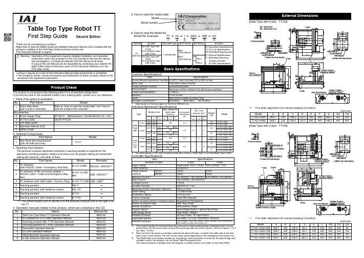
Table Top Type Robot TTFirst Step Guide Second EditionThank you for purchasing our product.Make sure to read the Safety Guide and detailed Instruction Manual (CD) included with theproduct in addition to this First Step Guide to ensure correct use.This Instruction Manual is original.• Using or copying all or part of this Instruction Manual without permission is prohibited.• The company names, names of products and trademarks of each company shown in thesentences are registered trademarks.This product is comprised of the following parts if it is of standard configuration.If you find any fault in the contained model or any missing parts, contact us or our distributor.1. Parts (The option is excluded.)No.Part Name Model1Robot Main Body(with a built-in controller)Refer to “How to read the model plate” and “How toread the model of the controller.”Accessories2 Power Supply Plug AP-400-C (Manufacturer: Yamate Electric Co., Ltd.)3 I/O Flat Cable CB-DS-PIO0204 First Step Guide5 Operation Manual (CD)6 Safety Guide2. Optional ComponentsNo.Part Name Model1Main Body Mounting Bracket(with set bolts and nuts)TT-FT3. Teaching Tool (Option)The personal computer application software or teaching pendant is required for theoperations including program creation and setup such as position setting and parametersetting with teaching. Use either of them.No.Part Name Model Remarks1PC Software(with RS232C Cable + Emergency Stop Box)IA-101-X-MW RS232C→RS232C*12PC Software (USB conversion adapter +RS232C cable + Cable and Emergency StopBox)IA-101-X-USBMW USB→RS232C*13 PC Software (with USB Cable + Dummy Plug) IA-101-TT-USB USB→USB*14 Teaching pendant SEL-T -5 Teaching pendant (with deadman switch) SEL-TD -6 Teaching pendant IA-T-X -7 Teaching pendant (with deadman switch) IA-T-XD -*1 The communication port on the left is for the personal computer and on the right is forthe TT.4. Operation manuals related to this product, which are contained in the CD. Manual No.1 Table Top Type Robot TT Operation Manual ME01492 PC software IA-101-X-MW Operation Manual ME01543 Teaching pendant SEL-T/TD Operation Manual ME01834 Teaching pendant IA-T-X/XD Operation Manual ME01605 DeviceNet Operation Manual ME01246 CC-Link Operation Manual ME01237 PROFIBUS-DPOperationManual ME01538 X-SEL Ethernet Operation Manual ME01406. How to read the Model No.Model No. Example TT - A3 -I - 2020 - 05B - DV①②③④⑤⑥①Series②Type③Encoder type④XY Stroke⑤Z Stroke⑥OptionA2:Gate Type with2-axisC2:Cantilever Typewith 2-axis-TT(Normal) A3:Gate Type with3-axisC3:Cantilever Typewith 2-axisI: Incremental2020200×200mm4040400×400mm05B50mm10B100mmDV :DeviceNet SpecificationsCC :CC-Link SpecificationsPR :PROFIBUS SpecificationsET :Ethernet SpecificationsFT :Main Body MountingBracket includedP :I/O PNP SpecificationsBasic Specifications[Common Specifications]Item SpecificationsSurrounding air temperature・humidity0 to 40°C, Room Humidity 20% to 85% or lessMotor Type Pulse Motor (Servo Control)Position detection method Incremental EncoderDriving System Ball Screw (φ10mm, Rolled C10), Ball Screw Lead 6mmPositioning Repeatability± 0.02mmBacklash 0.1mm or lessGuide Direct Driven Infinite Circulation TypeAllowable Load Moment*1Ma:6•5N•m Mb:9.3N•m Mc:16.4N•m*1 Value found on the assumption of the life of 5000 km run[Individual Mechanism Specifications]Stroke (mm)Max. Speed foreach axes(mm/sec)Max. LoadCapacity(kg)*2TypeXAxisYAxisZAxisXAxisYAxisZAxisAcceleration/Deceleration(G) XAxisYAxisZAxisWeight(kg)Model200 200- 14.8 TT-A2-I-20202-axis400 400-300 0.310 5-33 TT-A2-I-404050300 280TT-A3-I-2020-05B200 20010030016.5TT-A3-I-2020-10B50300 280TT-A3-I-4040-05BGateTypewith 3-axis400 4001003000.3 10- 235TT-A3-I-4040-10B200 200- 16.3 TT-C2-I-20202-axis400 400-300 0.2-4-35 TT-C2-I-404050300 280TT-C3-I-2020-05B200 20010030018TT-C3-I-2020-10B50300 280TT-C3-I-4040-05BCantileverTypewith 3-axis400 4001003000.2 --237TT-C3-I-4040-10B*2 The load capacity in the case of rated acceleration is shown (Gate Type: 0.3G, Cantilever Type: 0.2G)[Controller Specifications]Item SpecificationsNumber of axes 2-axis 3-axisSupply voltage Single-phase 100 to 115VAC, 200 to 230VAC ± 10%Power frequency50Hz/60Hz100VAC 150VA 210VAPower-sourcecapacity 200VAC 155VA 215VAMaximum Current*33A (100VAC), 1.6A (200VAC) 4.2A (100VAC), 2.2A (200VAC)Rush Current*415A (100VAC), 30A (200VAC)Leakage Current0.75mAInsulation Strength 2000VAC for 1 min.Momentary Power Interruption Tolerance500μs or moreSpeed Setting 1 to 300mm/secAcceleration Setting0.01G to 0.3GProgram language Super SEL languageNumber of programs (Number of multitask programs)64 programs (16 programs)Number of program steps 6000 steps (Total)Number of positions 3000 positions (Total)Program Startup Special Digital Switch + Special Start SwitchData storage device Flash ROM + SRAM*5Standard I/O Board 16 Input Points / 16 Output PointsApplicable Field Bus DeviceNet / CC-Link / PROFIBUS / EthernetProtective functions Over-voltage, motor over current, motor overload, driver temperatureabnormality, encoder abnormality, etc.*3 The current reaches its maximum level when the servo-motor exciting phase is detected which is to beperformed in the first servo-motor turning ON processing after the power injection. (Normal: Approx. 1 to 2sec, Max.: 10 sec)*4 Rush current at the power connection continues for about 20 msec. Consider the safety rate at the timewhen rush current passes. The rush current value varies depending on the impedance of the power line.*5 The SRAM data is not battery backed up. Accordingly, when the power is turned off, the data of flags andvariables used in the program, are not saved. Take the greatest care.The same procedure is applied when the program or position data is not written on the Flash ROM.External Dimensions[Gate Type with 2-axis TT-A2]*1 Fine slider adjustment (for manual tweaking of position).(Unit mm)Model A B C DEFGXstYstTT-A2-I-2020 369.7 330 338.5 133.318524088.2200200TT-A2-I-4040 569.7 530 538.5 333.3385440188.2400400[Gate Type with 3-axis TT-A3]*1 Fine slider adjustment (for manual tweaking of position).(Unit mm)Model ABCDEFXst Yst ZstTT-A3-I-2020-05B 369.7 330 338.5 83.313524020020050TT-A3-I-2020-10B 369.7 330 338.5 83.3135240200200100TT-A3-I-4040-05B 569.7 530 538.5 283.333544040040050TT-A3-I-4040-10B 569.7 530 538.5 283.3335440400400100 Warning : Operation of this equipment requires detailed installation and operationinstructions which are provided on the CD included in the box this devicewas packaged in. It should be retained with this device at all times.A copy of the CD Manual can be requested by contacting your nearest IAISales Office listed at the back cover of the Instruction Manual or on theFirst Step Guide.[Cantilever Type with 2-axis TT-C2]*1Fine slider adjustment (for manual tweaking of position).(Unit mm)Model A B C D E F XstYst TT-C2-I-2020 405 320 135 120 310 42 200 200 TT-C2-I-4040 605 520 335 213.6 510 142 400 400[Cantilever Type with 3-axis TT-C3]*1 Fine slider adjustment (for manual tweaking of position).(Unit mm)Model A B C D E F Xst Yst Zst TT-C3-I-2020-05B 405 330.6 135 120 310 71 200 200 50 TT-C3-I-2020-10B 405 330.6 135 120 310 71 200 200 100 TT-C3-I-4040-05B 605 530.6 335 213.6 510 171 400 400 50 TT-C3-I-4040-10B 605 530.6 335 213.6 510 171 400 400 100Do not use this product in the following environment:• Location where the surrounding air temperature exceeds the range of 0 to 40°C • Location where condensation occurs due to abrupt temperature changes • Relative humidity less than 20%RM or greater than 85%RM • Location exposed to corrosive gases or combustible gases• Location exposed to significant amount of dust, salt or iron powder • Location subject to direct vibration or impact • Location exposed to direct sunlight• Location where the product may come in contact with water, oil or chemical dropletsWhen using the product in any of the locations specified below, provide a sufficient shield.• Location subject to electrostatic noise• Location where high electrical or magnetic field is present • Location with the mains or power lines passing nearbyInstallation and Noise Elimination1. There is a cooling vent hole on the main body’s rear panel section. Do not close the vent hole when the main body is installed.2. When it required to fix the main body, fix it as follows using the optional mounting brackets3. Protective Ground4. Noise Elimination Grounding (Frame Ground)Connect it using a soft copper wire with the diameter of 1.6 mm or more to the frame ground on the main body (Refer to the above figure).Do not share the ground wire with or connect to other equipment. Ground each controller. The same procedure is applied for the protective ground.5. Precautions Regarding wiring Method6. Noise Sources and EliminationCarry out noise elimination measures for power devices on the same power path and in the same equipment. The following are examples of measures to eliminate noise sources:①AC solenoid valves, magnet switches and relays [Measure] Install a Noise killer parallel with thecoil.②DC solenoid valves, magnet switches and relays [Measure] Install a diode parallel with the coil.Use a DC relay with a built-in diode.Table Top TTTable Top TTOther equipmentOther equipment Other equipment+24V 0V4-M4 Depth 82- φ 4H7 Depth 5(Cable Projection Length)7.34.34.31.837.430304250Z-Slider Set Hole Section4-M5 Depth 10T-Groove SectionRear Panel Section*1 For the selection of the circuit breaker, perform it according to the following items.Breaker Teaching pendant Value > Power Capacity ÷ AC Input Voltage(Refer to the item for the controller specifications for the power capacity).•The current reaches the maximum level when the servo-motor is turned on and theservo-motor exciting phase is detected. Select the circuit breaker rated current thatdoes not trip the maximum current.• Select the circuit breaker that does no trip with the rush current described in thecontroller specifications.(Refer to the operating characteristic curve described in the manufacturer’s catalog.)• For the rated breaking current for the circuit breaker, select the breaking current valuewith which the current can be securely broken down even when short-circuit currentpasses.Rated Breaking Current > Short-circuit Current = Primary Power SupplyCapacity/Power Voltage.• Select the breaking current value for the circuit breaker leaving some margin.*2When the leakage breaker is to be installed, it is required to select it with the purposeclarified such as protection from fire or human body protection.Measure the leakage current at the location where the leakage breaker has beeninstalled.Use the “applicable to higher harmonics type” leakage breaker.Input*1Set the input functions using the I/O parameter Nos. 30 to 45 (Input Function Selection 000 to 015) and set the port Nos.that assign the each of the set functions, using the I/O parameter Nos. 282 to 298.*2If the input function selection 000 (program start) is assigned to any port except for the Port No. 000, the start switch onthe front panel is disabled.*3When the input function selection 007 to 013 (program No. designating digital switch) are assigned to any port except forthe port Nos. 007 to 013, the program change digital switch on the front panel is disabled.Output*4Set the output functions using the I/O parameter Nos. 46 to 61 (Output Function Selection 300 to 315) and set the portNos. that assign the each of the set functions, using the I/O parameter Nos. 299 to 314. Also, setting the output functionsusing the I/O parameter Nos. 331 to 346 (Output Function Selection 300 Area 2 to 315 Area 2) and setting the Port Nos.that assign the each of the set functions, using the I/O parameter Nos. 315 to 330, are available.When the system output signal is output to the I/Os on the above table, use the Output Function Selection Area 2.*5Because the output function selections 300 to 304 are allocated to the LEDs on the panel window, when the parameters of46 to 50 are set to universal output, or the Port No. allocation is changed using the parameter 299 to 303 settings, theLEDs are disabled.I/O Flat Cable (Accessories) CB-DS-PIO020No.Color Wirings No.Color Wirings1BR118GY22RD 119WT 23OR120BK24YW121BR35GN 122RD 36BL123OR37PL124YW38GY125GN39WT126BL310BK 127PL 311BR 228GY 312RD 229WT 313OR 230BK 314YW 231BR 415GN 232RD 416BL 233OR 417PL 2Flat cable(Presswelding)34YW 4Flat cable(Presswelding)I/O Circuit DiagramsNPN Specifications PNP SpecificationsPinNo.ElectricwirecolorPortNo.Function inStandardSetting(in Delivery)1 BR1 -I/O PowerSource +24V2 RD1 016UniversalInput3 OR1 017UniversalInput4 YW1 018UniversalInput5 GN1 019UniversalInput6 BL1 020UniversalInput7 PL1 021UniversalInput8 GY1 022UniversalInput9 WT1 023UniversalInput10 BK1 024UniversalInput11 BR2 025UniversalInput12 RD2 026UniversalInput13 OR2 027UniversalInput14 YW2 028UniversalInput15 GN2 029UniversalInput16 BL2 030UniversalInput17 PL2 031UniversalInputRemarksIt is set to the universal input when it is delivered. However, the change of the inputfunction is available with the I/O parameter setting.Parameter*1No. Parameter Name Remarks30 Input function select 000*21: Program Start31 Input function select 001 0: Universal Input1: Software Reset32 Input function select 002 0: Universal Input1: Servo ON signal33 Input function select 003 0: Universal Input1: Program automatically started when the power ON is reset inAUTO mode and software is reset2: Automatic Starting Program Signal34 Input function select 004 0: Universal Input1: All servo-axes soft interlock (OFF level)35 Input function select 005 0: Universal Input1: Pause Release (ON edge)36 Input function select 006 0: Universal Input1: Pause Signal (OFF level)37 Input function select 007*30: Universal Input1: Program No. appointment (LSB)38 Input function select 008*30: Universal Input1: Program No. appointment(The second bit)39 Input function select 009*30: Universal Input1: Program No. appointment(The third bit)40 Input function select 010*30: Universal Input1: Program No. appointment(The fourth bit)41 Input function select 011*30: Universal Input1: Program No. appointment(The fifth bit)42 Input function select 012*30: Universal Input1: Program No. appointment(The sixth bit)43 Input function select 013*30: Universal Input1: Program No. appointment(MSB : The seventh bit)2: Error Reset(ON edge)44 Input function select 014 0: Universal Input1: Driving Power Interruption Cancellation Input (ON Edge)45 Input function select 015 0: Universal Input1: All Effective Axes Homing (ON Edge)2: All Increment Effective Axes Homing (ON Edge)PinNo.ElectricwirecolorPortNo.Function inStandardSetting(in Delivery)18 GY2 316UniversalOutput19 WT2 317UniversalOutput20 BK2 318UniversalOutput21 BR3 319UniversalOutput22 RD3 320UniversalOutput23 OR3 321UniversalOutput24 YW3 322UniversalOutput25 GN3 323UniversalOutput26 BL3 324UniversalOutput27 PL3 325UniversalOutput28 GY3 326UniversalOutput29 WT3 327UniversalOutput30 BK3 328UniversalOutput31 BR4 329UniversalOutput32 RD4 330UniversalOutput33 OR4 331UniversalOutput34 YW4 -I/O PowerSource 0VRemarksIt is set to the universal output when it is delivered. However, the change of the outputfunction is available with the parameter setting.Parameter*4No. Parameter Name Function46331Output function select 300*5Output function select 300(Area 2)0: Universal Output1: Error Output at the operation cancellation level or more (ON)2: Error Output at the operation cancellation level or more (OFF)3: Error Output at the operation cancellation level or more +emergency stop output (ON)4: Error Output at the operation cancellation level or more +emergency stop output (OFF)47332Output function select 301*5Output function select 301(Area 2)0: Universal Output1: READY Output (PIO Trigger Program Operation Available)2: READY Output (PIO Trigger Program Operation Available)and without occurrence of any error at the operationcancellation level or more3: READY Output (PIO Trigger Program Operation Available)and READY Output (PIO Trigger Program OperationAvailable, and without occurrence of any error at the cold startlevel or more or more level or more48333Output function select 302*5Output function select 302(Area 2)0: Universal Output1: Emergency-stop output(ON)2: Emergency-stop output(OFF)49334Output function select 303*5Output function select 303(Area 2)0: Universal Output1: AUTO Mode Output2: Output during the Automatic Operation (In addition, when theparameter No. 12 is set to “1”)50335Output function select 304*5Output function select 304(Area 2)0: Universal Output1: Output at the time of “All Effective Axes Homing (=0)”2: Output when all the effective axes homing is completed3: Output when all the effective axes home preset coordinatesare set51336Output function select 305Output function select 305(Area 2)0: Universal Output2: Output during the first axis servo ON52337Output function select 306Output function select 306(Area 2)0: Universal Output2: Output during the second axis servo ON53338Output function select 307Output function select 307(Area 2)0: Universal Output2: Output during the third axis servo ON54339Output function select 308Output function select 308(Area 2)0: Universal Output55340Output function select 309Output function select 309(Area 2)0: Universal Output56341Output function select 310Output function select 310(Area 2)0: Universal Output57342Output function select 311Output function select 311(Area 2)0: Universal Output58343Output function select 312Output function select 312(Area 2)0: Universal Output59344Output function select 313Output function select 313(Area 2)0: Universal Output60345Output function select 314Output function select 314(Area 2)0: Universal Output61346Output function select 315Output function select 315(Area 2)0: Universal OutputWhen using this product for the first time, make sure to avoid mistakes and incorrect wiring by referring to the procedure below.Set-up for operation is completed.TroubleshootingThe following alarm displays are frequently generated at the start-up operation.Head Office: 577-1 Obane Shimizu-KU Shizuoka City Shizuoka 424-0103, JapanTEL +81-54-364-5105 FAX +81-54-364-2589website: www.iai-robot.co.jp/Ober der Röth 4, D-65824 Schwalbach am Taunus, GermanyTEL 06196-88950 FAX 06196-889524SHANGHAI JIAHUA BUSINESS CENTER A8-303, 808, Hongqiao Rd. Shanghai 200030, ChinaTEL 021-6448-4753 FAX 021-6448-3992website: Technical Support available in USA, Europe and ChinaHead Office: 2690 W. 237th Street, Torrance, CA 90505TEL (310) 891-6015 FAX (310) 891-0815Chicago Office: 110 East State Parkway, Schaumburg, IL 60173TEL(847) 908-1400 FAX (847) 908-1399TEL (678) 354-9470 FAX (678) 354-9471website: Atlanta Office: 1220 Kennestone Circle, Suite 108, Marietta, GA 30066825 PhairojKijja Tower 12th Floor, Bangna-Trad RD., Bangna, Bangna, Bangkok 10260, ThailandTEL +66-2-361-4458 FAX +66-2-361-4456Manual No.: ME0205-2D。
xtait M2 维护模式与即将上线 ver. 1.2.1 用户指南说明书

xtait
INTRODUCTION
The extension helps to create a customizable maintenance page instead of the default “Service temporarily unavailable”. You can configure any element on the page - structure, text, colors, and a background image. The page contains a countdown timer to show when the site is back available again.
The extension has a GDPR support function. When visitors want to get notifications, they have to mark a checkbox to agree to Privacy Policy and proceed with age confirmation and parent control.
T3002快充充电器说明书

7.10T3002 Fast Charger7.10.1IntroductionThe T3002-0000 single desktop fast charger is designed to charge T3000 rechargeable battery packs, with a slot for either the combined battery and radio or for the battery alone. The charger has a discharge function, activated by the button on the side of the charger and a capacity check feature, providing an indication of battery capacity.The charger is powered by either a dedicated T952 AC/DC plug pack, complying with the local requirements of the country into which it is sold, or a suitable DC supply.Although the T3002 is primarily intended for use in desktop situations, it may be used in vehicles with a nominal 12V supply voltage, in conjunction with the T952-050 vehicle supply cable. The vehicle supply cable is 1.5m long and has a cigarette lighter adapter plug at one end and a DC jack (centre pin positive) at the other.The T3002, T3002 plug packs and vehicle supply cable are available under the following IPNs:T952-050V ehicle Supply CableT952-012T3002 Plug Pack New Zealand\AustraliaT952-022T3002 Plug Pack UKT952-032T3002 Plug Pack EuropeT952-042T3002 Plug Pack USA/CanadaT3002-0000T3002 Fast Charger7.10.2Performance SpecificationsPower Supply..10.8 to 16V DC, 13W maximumBattery Capacity..up to 2AHBattery Types..NiCd and NiMHOperating Temperature..+5°C to +40°C (best performance+15°C to +25°C)between Fast Charge Rate..800mADischarge Rate..400mATrickle Charge Rate:NiCd..115mANiMH..50mAStandby Charge Rate.. 2.2mACharge Duration:Fast (for an exhausted battery pack):NiCd.. 1.5 hours (typical)NiMH.. 2.5 hours (typical)Trickle:NiCd.. 1 hoursNiMH.. 2 hoursStandby..indefiniteEnd Of Charge Detection..- high voltage- ∆T (rate of temperature rise)- negative ∆V- high temperature cut-off- safety timer7.10.3WarningsAvoid extreme temperatures and direct sunlight when charging a T3000 batterypack. The required temperature range for the charger is 5°C to 40°C. Chargingefficiency is maximised around normal room temperature i.e. 15°C to 25°C.•T o give maximum battery life, do not recharge the battery until the ‘low battery warning’ is activated. This will avoid reduced battery capacity.7.10.4OperationPlace the charging unit on a stable horizontal surface and power the unit either from the T952 plug pack or the T952-050 vehicle supply cable.Check that the connectors are properly pushed home to ensure reliable electrical contact.Place the battery to be charged, with or without its radio, into the charging unit with the 4 contacts to the rear.•To locate a battery pack correctly in the charger, lean the top of the battery as far for-ward as possible to seat the bottom of the battery . Pivot the battery back against the contacts and it should snap into place.•After fast charging, the charge current terminates. The green LED then illuminates,indicating that trickle charge has commenced.•The battery may be left in the charger until needed, where it will be trickle orstandby charged, with no risk of damage.•The indicator beside the pocket indicates the charge status, as shown in the follow-ing table.7.10.4.1Discharge FunctionRegular discharging of the battery (at least weekly) will result in longer battery life.Note:The ‘discharge before charge’ feature can only be used on batteries with a date codenext to the serial number (e.g. G95). Earlier batteries cannot be discharged using a T3002.Press the discharge button to initiate a discharge-charge cycle.LEDConditionFunctionoffchargingsuspended•Incorrectly seated battery .•Charger powered but no battery present.•No power connected.amberwaitingBattery present, but awaiting charge while battery is being tested (3 seconds), or until the battery is within the correct temperature range for charging.green flashing discharging Battery is being being completely discharged.red fast charge Fast charge in progress.green standby charge Fast charge complete - trickle or standby charge in progress.red flashingfaultCharge suspended - faulty battery , or faulty charger.7.10.4.2Cycle & Capacity CheckIntroductionThe T3002 fast charger has a cycle and capacity check feature that discharges and charges a NiMH battery pack for 2 cycles, and a NiCd battery pack for 3 cycles. This means that the battery can be cycled and the capacity checked within a 16 hour period. The charger will then provide an indication of the batteries capacity.The cycle and capacity check function can also be used to rejuvenate batteries that have been stored without use for a significant time, or those suffering from reduced capacity through lack of regular exercise.When the T3002 is in the ‘cycle and capacity check’ mode, any discharge request by the user pressing the discharged button is ignored until the last charge cycle.Note:The capacity check feature can only be used on batteries with a date code next to the serial number (e.g. G95). Earlier batteries cannot be discharged using a T3002. ProcedureInsert the battery in the charger, while holding down the discharge button.Depress the discharge button until the indicator LED has changed from amber (battery being tested) to flashing green (battery discharging). The charger is now in ‘cycle and capacity check’ mode.Battery CapacityThe last battery discharge cycle is timed to give an approximate battery capacity. The indicator LED gives the charge and capacity status, as shown in the following table.LED Condition Functionamber waiting Battery present, but awaiting charge while battery is being tested (3 seconds), or until the battery is within the correct temperature range for charging.green flashing dischargingBattery is now discharging and is in ‘cycle and capacity check’mode.amber flashing low capacityBattery is less than 70% of the rated capacity, and will be leftdischarged.green capacity adequate Battery capacity is adequate. Fast charge is complete and trickle or standby charge is in progress.7.10.5Circuit DescriptionRefer to the T3002 block diagram, shown below.The DC supply to the charger feeds the 11.7V and 5V regulators, via a fuse.•The 11.7V regulator supplies the current source, LED, voltage interface and tempera-ture cutout circuitry.•The 5V regulator supplies the microprocessor and low voltage indicator (LVI) cir-cuitry.Battery voltage, temperature and capacity information is presented to the microproces-sor via the internal analogue to digital converter. V oltage information arrives through interface circuitry, that provides a normal battery voltage signal and an expanded volt-age signal (from 8.24V to 10.5V).This information, and any discharge request via the discharge button, is used by the microprocessor to appropriately switch on either the charging current source or the dis-charge circuitry.During charging, the current source is either continuously switched on (fast charge), or switched on and off at an appropriate duty cycle to provide trickle or standby charging. The exact state of the microprocessor is indicated to the user via the charger LED.The microprocessor can be put into a reset state if either of the following conditions occur:•The supply voltage drops and activates the LVI circuitry.•The internal charger temperature gets too hot and activates the temperature cut-out circuitry.T3002 Parts List (IPN 220-01342-01)Ref VAR IPN Description Ref VAR IPN Description!C1018-14100-00CAP 0603 CHIP 1N 50V X7R +-10%!C2018-16100-01CAP 0603 CHIP 100N +80-20% Y5V 16V!C3018-14100-00CAP 0603 CHIP 1N 50V X7R +-10%!C4018-14100-00CAP 0603 CHIP 1N 50V X7R +-10%!C5018-16100-01CAP 0603 CHIP 100N +80-20% Y5V 16V!C15018-16100-01CAP 0603 CHIP 100N +80-20% Y5V 16!C16018-16100-01CAP 0603 CHIP 100N +80-20% Y5V 16!C17018-16100-01CAP 0603 CHIP 100N +80-20% Y5V 16!C18018-16100-01CAP 0603 CHIP 100N +80-20% Y5V 16!C19018-14100-00CAP 0603 CHIP 1N 50V X7R +-10%!C20018-12330-00CAP 0603 CHIP 33P 50V NPO +-5%!C21018-12330-00CAP 0603 CHIP 33P 50V NPO +-5%!C22018-14100-00CAP 0603 CHIP 1N 50V X7R +-10%!C25018-15100-00CAP 0603 CHIP 10N 50V X7R +-10%!C30018-16100-01CAP 0603 CHIP 100N +80-20% Y5V 16!C40018-14100-00CAP 0603 CHIP 1N 50V X7R +-10%!C41018-12180-00CAP 0603 CHIP 18P 50V NPO +-5%!C42018-12180-00CAP 0603 CHIP 18P 50V NPO +-5%!C43018-16100-01CAP 0603 CHIP 100N +80-20% Y5V 16!C44018-12180-00CAP 0603 CHIP 18P 50V NPO +-5%!C45018-12180-00CAP 0603 CHIP 18P 50V NPO +-5%!C46018-14100-00CAP 0603 CHIP 1N 50V X7R +-10%!C47018-16100-01CAP 0603 CHIP 100N +80-20% Y5V 16!C48018-14100-00CAP 0603 CHIP 1N 50V X7R +-10%!C49016-08100-01CAP ELECT 6X4MM CHIP 10M 20% 16V !C50018-14100-00CAP 0603 CHIP 1N 50V X7R +-10%!C51018-16100-01CAP 0603 CHIP 100N +80-20% Y5V 16!C52018-16100-01CAP 0603 CHIP 100N +80-20% Y5V 16!C55018-16100-01CAP 0603 CHIP 100N +80-20% Y5V 16!C56018-14100-00CAP 0603 CHIP 1N 50V X7R +-10%!C57018-14100-00CAP 0603 CHIP 1N 50V X7R +-10%!C58018-12180-00CAP 0603 CHIP 18P 50V NPO +-5%!C60018-16100-01CAP 0603 CHIP 100N +80-20% Y5V 16!C61016-08100-01CAP ELECT 6X4MM CHIP 10M 20% 16V!D1001-00012-77(S) DIODE 1N6277A ZENER 18V 1500W!D3008-02099-00(S) LED RED/GREEN BI-COLOUR 3.1MM !D4001-10000-70(S) DIODE SMD BAV70 DUAL SWITCH SO !D6001-10000-70(S) DIODE SMD BAV70 DUAL SWITCH SO !D9001-10000-70(S) DIODE SMD BAV70 DUAL SWITCH SO !D12001-10014-03(S) DIODE SMD MBRS140T3 SCHOTTKEY!IC1002-00078-05(S) IC MC7805ACT 5V REG(LINEAR)1A!IC4002-06870-51(LS) IC MC68HC705P6P OTP MICRO 28!IC4A240-04020-95(L) SKT SMD DIP 28!IC5002-10340-64(S) IC SMD MC34064 LO VOLT SENSE!IC8002-10003-24(S) IC SMD 324 QUAD OP AMP SO14!Q1000-00295-50(S) XSTR MTP2955 FET TO-220!Q3000-10084-81(S) XSTR SMD BC848BW NPN SOT-323 S !Q4000-10084-81(S) XSTR SMD BC848BW NPN SOT-323 S !Q5000-10084-81(S) XSTR SMD BC848BW NPN SOT-323 S !Q6000-00295-50(S) XSTR MTP2955 FET TO-220!Q7000-10084-81(S) XSTR SMD BC848BW NPN SOT-323 S !Q8000-00012-49(S) XSTR TIP31 NPN PWR SWTCH TO220 !Q9000-10084-81(S) XSTR SMD BC848BW NPN SOT-323 S !Q10000-10084-81(S) XSTR SMD BC848BW NPN SOT-323!R2036-14470-10RES M/F 0805 CHIP 4K7 1%!R15038-14100-00RES 0603 CHIP 1K0 1/16W +-5%!R16036-15470-10RES M/F 0805 CHIP 47K 1%!R17036-13560-00RES M/F 0805 CHIP 560E 5%!R18036-15100-10RES M/F 0805 CHIP 10K 1%!R19038-17100-00RES 0603 CHIP 1M 1/16W +-5%!R20036-13820-00RES M/F 0805 CHIP 820E 5%!R21036-13560-00RES M/F 0805 CHIP 560E 5%!R22036-16120-10RES M/F 0805 CHIP 120K 1%!R23036-15100-10RES M/F 0805 CHIP 10K 1%!R24036-15470-10RES M/F 0805 CHIP 47K 1%!R25038-17100-00RES 0603 CHIP 1M 1/16W +-5%!R30036-16100-10RES M/F 0805 CHIP 100K 1%!R31036-15180-10RES M/F 0805 CHIP 18K 1%!R32036-11180-10RES M/F 0805 CHIP 1E8 1%!R33038-14470-00RES 0603 CHIP 4K7 1/16W +-5%!R34038-14100-00RES 0603 CHIP 1K0 1/16W +-5%!R35038-14470-00RES 0603 CHIP 4K7 1/16W +-5%!R36038-14100-00RES 0603 CHIP 1K0 1/16W +-5%!R37036-11180-10RES M/F 0805 CHIP 1E8 1%!R38036-11180-10RES M/F 0805 CHIP 1E8 1%!R39036-11180-10RES M/F 0805 CHIP 1E8 1%!R45038-14100-00RES 0603 CHIP 1K0 1/16W +-5%!R46036-15100-10RES M/F 0805 CHIP 10K 1%!R47036-15100-10RES M/F 0805 CHIP 10K 1%!R48036-15100-10RES M/F 0805 CHIP 10K 1%!R49036-15100-10RES M/F 0805 CHIP 10K 1%!R50036-15390-10RES M/F 0805 CHIP 39K 1%!R51038-14470-00RES 0603 CHIP 4K7 1/16W +-5%!R52036-15390-10RES M/F 0805 CHIP 39K 1%!R53036-15390-10RES M/F 0805 CHIP 39K 1%!R54036-15100-10RES M/F 0805 CHIP 10K 1%!R55036-15100-10RES M/F 0805 CHIP 10K 1%!R56036-16120-10RES M/F 0805 CHIP 120K 1%!R57038-14100-00RES 0603 CHIP 1K 1/16W +-5%!R58036-15330-00RES M/F 0805 CHIP 33K 5%!R59038-14100-00RES 0603 CHIP 1K0 1/16W +-5%!R60036-15100-10RES M/F 0805 CHIP 10K 1%!R61036-15100-10RES M/F 0805 CHIP 10K 1%!R62036-11180-10RES M/F 0805 CHIP 1E8 1%!R63036-11180-10RES M/F 0805 CHIP 1E8 1%!R64036-11180-10RES M/F 0805 CHIP 1E8 1%!R65036-11180-10RES M/F 0805 CHIP 1E8 1%!R66036-11180-10RES M/F 0805 CHIP 1E8 1%!R67036-11180-10RES M/F 0805 CHIP 1E8 1%!R68036-11180-10RES M/F 0805 CHIP 1E8 1%!R69036-11180-10RES M/F 0805 CHIP 1E8 1%!R70036-11180-10RES M/F 0805 CHIP 1E8 1%!R71036-15390-10RES M/F 0805 CHIP 39K 1%!R72036-15100-10RES M/F 0805 CHIP 10K 1%!R75036-15100-10RES M/F 0805 CHIP 10K 1%!R76036-15100-10RES M/F 0805 CHIP 10K 1%!R77036-15100-10RES M/F 0805 CHIP 10K 1%!R78045-15100-00RES NTC SMD 10K 5%!R79045-15100-00RES NTC SMD 10K 5%!R80036-14120-00RES M/F 0805 CHIP 1K2 5%!R81036-14120-00RES M/F 0805 CHIP 1K2 5%!R82036-15470-10RES M/F 0805 CHIP 47K 1%!R83036-15180-10RES M/F 0805 CHIP 18K 1%!R84036-13560-00RES M/F 0805 CHIP 560E 5%!R86038-14100-00RES 0603 CHIP 1K0 1/16W +-5%!R87036-13560-00RES M/F 0805 CHIP 560E 5%!R88036-15180-10RES M/F 0805 CHIP 18K 1%!R89036-15100-10RES M/F 0805 CHIP 10K 1%!R90036-15100-10RES M/F 0805 CHIP 10K 1%!R91038-14100-00RES 0603 CHIP 1K0 1/16W +-5%!R92036-15100-10RES M/F 0805 CHIP 10K 1%!R93036-10000-00RES M/F 0805 CHIP ZERO OHM!SW1232-00010-29(L) SWITCH TACT 3.85MM RED STEM HSK1240-02020-07SKT DC JACK 5.5MM HOLE 2.5MM PIN!XL1274-00010-33XTAL 4MHZ TE-35 HC49U C/W TEFLON 220-01342-01(L) PCB T3002 SINGLE FAST CHARGER302-40038-00BUTTON RED T3002 OPERATING303-20051-01COVER TOP A1M2800 T3003 TRICKLE CHA303-20052-01COVER BTM A1M2801 T3003 TRICKLE CH303-50027-00CONTACT A3M2818 T3000 BAT CHARGER308-13110-00HSINK PCB MTG FOR VERT MNT TO220 C/308-13117-00HSINK TO-220 HOR PCB MOUNTING349-00010-22SCREW NO 4X3/8 PAN POZI PLASTITE365-00100-09LABEL WHITE VINYL 15X11MM S/A365-01450-00LABEL BLNK 38*9MM TAMPERMARK VOID365-01498-00LABEL MODEL ID T3002-0000369-00010-11FOOT RUBBER BUMP-ON S/A410-01100-00PKG A3A723 T3003 TRICKLE CHARGER459-30023-00USER GUIDE T3002 FAST CHARGERDevicePCBCircuitT3002 Grid Reference Index (IPN 220-01342-01)DevicePCBCircuitDevicePCBCircuit32:E11-L222:D01-L312:D11-L442:E01-L1!C11:H11-B8!C21:F31-C7!C31:F31-C7!C41:F31-D7!C51:F31-E7!C151:B51-A4!C161:C41-C4!C171:B51-D5!C181:B51-E5!C191:C31-A3!C201:D41-B1!C211:D41-B1!C221:A11-D3!C301:F31-G5!C401:C41-F2!C411:E31-G2!C421:E31-G2!C431:D21-G1!C441:E31-H2!C451:E31-H1!C461:E21-H0!C471:E21-H0!C481:F21-J2!C491:E21-J2!C501:C31-L3!C511:D21-L1!C521:E31-M5!C551:F41-A5!C561:F41-A5!C571:F41-B5!C581:F31-C6!C601:B01-F7!C611:E01-H7!D11:F41-C8!D32:H51-D21-E2!D41:D31-K31-K3!D61:E41-D61-D6!D91:F41-B51-B5!D121:F11-H3FUSE 1:H11-B8!HS-STUD 1:B1!HS 1:F2!IC11:G31-D7!IC41:B31-C2!IC4A 1:B31-C1!IC51:B51-E5!IC81:E31-L51-G31-G11-H51-C5!LINK12:G41-K7!LINK22:G51-J6!Q11:B11-G8!Q31:G41-D3!Q41:G41-E3!Q51:C41-F2!Q61:F21-H2!Q71:F21-J5!Q81:F21-J5!Q91:B01-F7!Q101:C01-G7!R21:B11-F8!R151:B51-B4!R161:B51-D6!R171:C21-A3!R181:A11-C3!R191:D41-B1!R201:G41-D3!R211:G51-E3!R221:C31-E1!R231:A31-C2!R241:A21-C2!R251:D31-F3!R301:E41-F6!R311:E41-F5!R321:F31-J4!R331:F21-H5!R341:F31-H5!R351:F31-H5!R361:F31-J5!R371:F31-J4!R381:F31-J4!R391:F31-J4!R451:C41-F2!R461:C31-F1!R471:C31-E1!R481:D31-F3!R491:D31-F3!R501:E31-G3!R511:D31-G2!R521:D31-G2!R531:D21-G1!R541:D31-G3!R551:D31-G3!R561:E31-G1!R571:E31-H2!R581:D31-H1!R591:F21-H2!R601:F21-H1!R611:E21-H0!R621:D11-H3!R631:D11-H3!R641:D11-H3!R651:E11-H3!R661:E11-J3!R671:E11-J3!R681:E11-J3!R691:E11-J3!R701:F11-J3!R711:D21-K3!R721:D21-K2!R751:E41-A6!R761:F41-A6!R771:F41-A5!R781:B11-B7!R791:G11-B7!R801:F41-B6!R811:F41-B6!R821:F31-B5!R831:F41-C6!R841:B51-D6!R851:F11-J2!R861:B01-F7!R871:B01-F6!R881:C01-G7!R891:C01-G6!R901:C01-H6!R911:B01-F7!R921:C31-F1!R931:C31-F1!R951:H51-E2!R2012:H51-J7!R2022:G51-K7!R2032:G51-K7!R2042:G21-J7!R2052:G21-J7SK11:J11-B8!SW11:A01-D3’TP12:F41-H7TP22:F41-B6TP32:F41-B6TP52:E41-D6!XL11:D41-B1T3002 Fast Charger PCB (IPN 220-01342-01) - Top CopperT3002 Fast Charger PCB (IPN 220-01342-01) - Bottom CopperM3000-00T3002 Fast Charger 7.10.11Copyright TEL30/04/96M3000-00T3002 Fast Charger7.10.1230/04/96。
TT快速入门手册2说明书
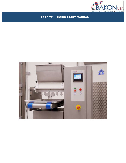
INDEXSECTION 1: General information•Power switch•Control panel•Passwords•Safety sensors•Stop button on the touch screenSECTION 2: Filling the pump•Purpose of filling pump•Roller Head•Pump HeadSECTION 3: Lowering and lifting table •Step by step instructionSECTION 4: Preprogrammed Recipes•25-30 Preprogrammed recipes•Copying and saving under a new name SECTION 5: Placing traysSECTION 6: Starting productionSECTION 7: Cleaning•Step by step instructions on breakdown for cleaning Section 8: ReassemblySection 9: Standard recipesSection 10: Adjusting recipesSECTION 1: General information1. The power switch is located on the back side of the machine2.Control panel description3. Passwords:∙Operator password 654321∙Supervisor password 4149904. Safety Sensors: There are three safety sensors on the machine∙Two proximity sensors ( Front and back of hopper)∙ 1 magnetic sensor on the hopper (Cover of the hopper)(Proximity Sensors)(Magnetic Sensor)*Note: Interrupting the sensors will stop the machine. To reset press the start switch, if it doesn’t r eset by pushing the green start button first unlock the emergency stop button by twisting to the right (it should pop out)5.Stop function on the touch screen: The operator can use this function in two ways5.1Press the stop tab to pause depositing briefly, then push start tab on touchscreen to resume depositing where it left off.5.2Press and hold the stop tab on the touch screen for 5 seconds it will stop, ejectthe tray and instruct you to push start. Push start and it will begin a new cycle.(5.1)(5.2)SECTION 2: Filling the pumpWhen starting production with batter in the hopper, the pump is empty. You couldmanually run the pump before starting production cycle will deposit the batter until pump is filled, ensuring your first tray of product will be complete. Once the pump has adequate amount of batter it will deposit a consistent stream. Now you can begin production.1. Add your batter to the hopper ( Be sure to close the lid properly)2. Place a tray on the conveyor to catch any batter under the nozzles3. Select Pump head for semi liquid batters.a. i.e. Macarons, Choux, éclairs, muffins• Using the touch screen press the wrench icon, then the pointing handicon. (The screen display should match the picture below.) Based on the batter select the correct pump and hold for a few seconds until your batter runs though the pump. Once the pump is depositing a consistent product you are ready to begin production.4. Select Roller head for dough like batters.a. i.e. Butter cookies• Same steps as described above.**Note: Roller head motion isinward, whereas Pump headmotion is outward.SECTION 3: Lowering and lifting the tableTo manually move the table up or down follow these instructions:1. Press the wrench icon on the touch screen2. Press the pointing hand icon3. Select the blue table tab4. The choice of up or down will pop up, just press and hold in the desired direction.SECTION 4: Pre-programmed RecipesThe machine has room for 30 PROGRAMS (recipes). Six of these programs are BASIC—EXAMPLE recipes factory set in order to make the programming easy and user-friendly. They can be found in position 25 to 30.Recipe N° Name Drop Picture25 FIX FIX DROP26 FIX FIX DROPTWISTED W/ NOZZLEROTATION27 LONG DROP long drop28 LONG long drop w/TWISTED nozzle rotation29 WIRE CUT drop cut30 WIRE CUT long dropLONG cutSECTION 4: Recipes Continued1. Selecting a preprogrammed recipe:∙Press the Recipe book icon and enter the recipe list, navigate through the recipe’s using the blue arrows and choose the recipe. Press the recipe tohighlight the tab.∙Press the green arrow icon a box will pop up, push yes to confirm (The name on the grey line will match the name on the yellow line)∙Press the home icon2. Copying a preprogrammed recipe:∙Return into the recipe index by following the steps above∙Select the recipe you’d like to copy. Press the recipe to highlight it yellow.∙Hit the floppy disc icon, a box will pop up select Yes. You have successfully copied that recipe.∙Look for and select a blank spot to paste the copied recipe, select that spot by press to highlight it yellow.∙Press the Disc icon, key in the password.∙Press the disc icon, yes to confirm. You have saved that recipe, now you can rename it.3. Renaming the copied recipe∙Select the recipe you just copied and pasted by pressing the yellow tab where it is located∙Once in the recipe, press the highlighted tab where the name is displayed. A keypad will pop up∙Using the keypad type in the name you would like to use for this recipe. Hit the enter button on the keypad.∙Now you are able to modify all the data for that recipe without effecting the original that was copied.SECTION 5: Placing trays1. Press the green START button on the touch screen; the machine starts cycle aGreen tab will turn on display “IN CYCLE”. The conveyor starts running and theMachine is ready to deposit.2. Place a tray on the conveyor, make sure you use only flat trays, the tray startsmoving forward and when it reaches the tray Sensor the dosing cycle will start.Based on the pan configuration programmed (example: 9 rows) the cycle will stop once completed, if no other trays are placed. If other trays are placed after the first one, the tray coming out from the conveyor must be collected by the operator.Make sure to leave 2 inches of space when placing the next tray, in order for the tray sensor to come up.3 The guide can be adjusted vertical and horizontal. Make sure the guide is always lower than the conveyer.SECTION 6: Starting production1. Turn on machine and press the touch screen2. Place a tray under the nozzle to collect batter while filling the pump3. Fill the hopper4. Reset (once hopper lid is properly closed)5. Fill the pump manually (see section 2)6. Remove collecting tray once all the nozzles are full7. Press start8. Place a tray on the belt and the machine will start depositing9. Place the next tray if you want to continue depositing, make sure you leave 2inches distance between trays.SECTION 7: Cleaning1. Place tray under depositor, run the pump manually (see section 2) until as muchbatter as possible is deposited.2. Carefully remove the hopper, pump, nozzles. Wash with soap and water. Be sureto dry thoroughly. (See below for step by step removing)1. Replace the seal for the Hopper. Be sure to pay special attention to theplacement of the seal. It should be flush with the hopper.Incorrect placementCorrect placement2. Replace the hopper, be sure to pay special attention to the placement. The widerpart of the Hopper should be the back side ( The back is where the power button is)Incorrect placementSection 9: Standard recipesSection 10: Adjusting recipesPress on the product to go into the recipeWith depositing time you can in- or decrease the size of the product.Pan; determines how many rows you want on the tray, the distance from the edge of the tray for the first deposit and the distance between rows.Table: height of the table is the height between the tray and the spouts at the time of depositSuction: after each deposit rollers reverse a little bit while the tray moves forwardAdvanced: tip off only used for depositing of eclairs.Press blue arrow to back to product screenYou can either deposit now and save settings later, or save settings now. To save now press on bookPress on the disk and enter your passcodePress disk againconfirm saving new settingsGo back to home。
TZ-002规格书(2G通信模块)

硬件描述
Doc Name
TZ -ቤተ መጻሕፍቲ ባይዱ002 硬件描述
Version
Date Doc ID
2014/1/7
TZ-002
Status
Release
拟制
审核
批准
2014/1/7
1 / 21
内容目录
内容目录
内容目录 ................................................................................................................................... 2 图表目录 ................................................................................................................................... 4 1 序 ....................................................................................................................................... 5
1.1 相关文档 ............................................................................................................ 5 1.2 缩写 .................................................................................................................... 5 2 产品概述 ........................................................................................................................... 7 3 应用接口 ........................................................................................................................... 7 3.1 接口概览 ............................................................................................................ 7 3.2 工作状态 ............................................................................................................ 8 3.3 状态指示 ............................................................................................................ 8
- 1、下载文档前请自行甄别文档内容的完整性,平台不提供额外的编辑、内容补充、找答案等附加服务。
- 2、"仅部分预览"的文档,不可在线预览部分如存在完整性等问题,可反馈申请退款(可完整预览的文档不适用该条件!)。
- 3、如文档侵犯您的权益,请联系客服反馈,我们会尽快为您处理(人工客服工作时间:9:00-18:30)。
一、 整流模块简介
TT 系列电力专用高频开关整流模块采用先进的谐振式软开关技术;专门针对各类变电站、电厂及其他直流供电场合的直流屏而设计。
TT 系列整流模块采用智能风冷的散热方式,具有高效率,高密度,高功率因数、高可靠性等特点,同时具有造型美观、占用空间少;采用2U*4U 标准设计,内置防倒灌二极管,方便客户组屏。
TT 系列总包括4款型号:TT11010-T/TT22005-T/TT11020-T/TT22010-T; 4款整流模块采用统一外观,统一机箱,统一开孔尺寸,方便客户选型设计。
整流模块型号说明见下图:
TT22010-T 整理模块型号说明
工作原理:
整流模块工作原理图如下所示:
交流输入 直流输出
485通信
输入EMI PFC DC/DC 整流滤波 输出EMI
输入检测和保护 辅助电源 输出检测 温度检测 DC/DC 保护控制
监控模块
二、外观及接口
1.整流模块外观
TT22010-T整流模块外观
2.前面板
TT22010-T整流模块前面板
1)LED指示灯
(红色)
故障指示灯
灭 亮
输出欠压保护E36 风扇故障E37 (具体信心参见故障代码)
2) 数码管
可显示模块电压、电流、地址、告警等信息。
若按键无操作超过大约30秒后,将自动显示模块电压,此时如果存在告警,则显示故障代码。
电压显示精度为±1V ,电流显示精度为±。
3) 微调旋钮
由于不同用户现在蓄电池的节数有差异,可以通过拨码开关设置整流模块为手动调压时,整流模块输出电压自动调整到出厂设定值235V(标称220V 模块)或121V (标称110V 模块),为了安全起见,非专业人员请勿操作。
4) 显示按钮
默认为显示电压,按下时依次显示输出电压、输出电流、模块地址。
5) 拨码开关设置
拨码开关用于设置整流模块的控制方式、模块组号、模块地址,1号为最低位,4号为最高位。
模块地址设置请参照下表:
二进制与十进制对应关系表
0 1
模块地址 (0~15) 模块组号 (1~2)
控制模式(ON:手动、OFF:自动)
二进制0000000100100011010001010110011110001001101010111100110111101111十进制0123456789101112131415
整流模块地址通过拨码开关1234号位设置地址,可设置范围为0~15,亦即每组整流模块的最大并机数为15个。
通过拨码开关第5号位设置模块分组号,可设置范围1~2组。
整流模块只在相同分组号组内进行均流,组间不均流。
不同整流模块S485总线可以串联到主监控单元的同一组S485接口,实现一个主监控单元对多个整流模块组的控制管理。
整流模块地址是监控单元识别个整流模块的唯一标志,同一电源系统中整流模块的地址设置(分组号+模块地址)不能相同。
对于同一个整流模块通信地址设置必须与监控单元中的整流模块地址设置相同,否则异常。
通过拨码开关的第6号位设置手动控制和自动控制(ON:手动、OFF:自动);在自动控制方式下,整流模块的输出电压、限流点、开关机均由监控单元进行控制,人工无法进行干预。
如果整流模块连接到合闸母线上对电池进行充电,一般应设置为自动控制方式。
在手动控制方式下,整流模块的输出电压、限流点、开关机均不接受监控单元控制,但可以将整流模块的运行参数上报给监控单元。
如果整流模块连接到控制母线上,则整流模块只输出单一的稳定电压,限流点全部放开,为110%。
手动控制方式下的整流模块与自动控制方式下的整流模块之间不均流。
3.接口定义
接口定义图
信号名称引脚号接口定义说明
直流输出1直流输出负
注意正负输出,切勿接反2直流输出正
保护地3接大地PE保护地,请可靠连接
均流接口6SHARE-
模块直接相互对应连接9SHARE+
通信接口7RS485B与监控单元S485通信时,请选用屏蔽
线以串联方式连接
10RS485A
交流输入13交流输入U
交流输入为三相三线制,无相序要求14交流输入V
三、参数指标
注:海拔超过2000m需要降额使用,降低工作环境温度1°C/100m.
绝缘电阻与绝缘强度
1、绝缘电阻
输入端、输出端对外壳之间以及输入对输出之前的绝缘电阻>2MΩ。
2、绝缘强度
输入端、输出端段节后,在输入/输出端与外壳之间施加2000V交流电压1分钟,无击穿或飞弧现象。
四、其他功能
1.保护功能
整流模块具有以下保护功能:输入过/欠压保护,输出过/欠压保护,输出欠压告警、短路保护、缺相保护、过温保护和风扇故障告警。
整流模块保护/告警信息以故障代码形式在LED上实时显示,故障代码如下:
2.通信功能
整流模块内置ENPC和MODUS两种通信协议,可自动识别。
整流模块通过S485方式与监控单元通信,将整流模块输出电压和电流,整流模块保护和告警信息发送给监控单元。
在自动方式下,接受并执行监控单元下发的控制命令。
在手动方式下,整流模块不接受监控单元的控制。
具体通信功能见下表。
五、安装设计
整流模块机械参数
整流模块外形尺寸(长*宽*高):325×88×178mm
单模块托架参数
单模块托架安装尺寸图
如果采用天英公司提供托架固定(请按照固定孔位开φ5通孔即可,面板本身不需压铆),安装流程如下:第一步将航空插座固定在托架上
模块托架安装航空插座图
第二步将托架固定在两根横梁上,如图所示:
模块托架固定横梁图
1、整流模块采用智能风冷散热方式,风扇安装于模块前部,从整流模块前方抽风吹向模块后方。
因此在安排模块位置时,应保证模块前后散热风道的畅通;建议整流模块之前间隔15~20cm。
同时,整流模块后方尽量少安装敏感部件,设计是尽量避免直流传感器、温度传感器、采样单元盒等器件安装到风道附近。
2、模块具备热插拔功能,但禁止在易燃环境中对模块进行热插拔;模块不应直接连接到系统交流母线上;为了方便模块的单个维护,模块交流输入进线处应分别设置单独的空气开关。
3、电缆可以选择非屏蔽电缆,根据实际情况选取适当长度的电缆。
为方便使用,我司可提供模块的配套插框,供客户选购。
六、包装、运输与故障处理
产品包装
本产品外包装采用专用纸箱,内包装采用防震材料进行包装,不可回收!
运输
本产品因在包装完好的情况进行运输,严禁在运输过程中存在剧烈震动和撞击;同时防止受潮,雨淋。
温馨提示:因整流模块在系统上只靠面板上M4螺钉固定以防止整流模块滑落,没有与机柜紧固连接。
直流屏机柜在运输时,请务必将整流模块取下,单独包装运输,严禁将整流模块安装于直流屏机柜上运输,否则将造成系统机柜和整流模块损坏。
故障处理
________________________________________________________________________
注意:
未经许可,严禁擅自打开整流模块外壳。
否则,由此造成的设备损坏及人身伤害天英公司概不负责;
同时,由此造成的技术泄密,天英公司保留追究相关法律责任的权利.
________________________________________________________________________
模块常见故障表现有:电源指示灯(绿色)灭、保护指示灯(黄色)亮、故障指示灯(红色)亮。
同时数码管显示故障代码。
常见故障代码及处理如下:
安全注意事项
在开始操作之前,请仔细阅读操作指示、注意事项,以减少意外的发生。
产品及产品手册中的“小心、注意、警告、危险”事项,并不代表所应遵守的所有安全事项,只作为各种操作安全注意事项的补充。
因此,负责天英公司产品安装、操作的人员必须经严格培训,掌握系统正确的操作方法及各种安全注意事项后方可进行设备的各项操作。
在进行本公司产品、设备的各项操作时,必须遵守相关行业的安全规范,严格遵守由天英公司提供的相关设备注意事项和特殊安全指示。
高压
危险
交流电源设备的安装,必须遵守相关行业的安全规范,进行交流设备安装的人员,必须具有高压、交流电等作业资格。
操作时严禁在手腕上佩带手表、手链、手镯、戒指等易导电物体。
发现机柜有水或潮湿时,请立刻关闭电源。
在潮湿的环境下操作时,应严格防止水分进入设备。
安装过程中不能容许操作的开关和按扭上,必须挂上禁止标识牌。
电池
危险
电池的不规范操作会造成危险。
操作中必须严格注意、小心防范电池短路或电解液溢出、流失。
电解液的溢出会对设备构成潜在性的威胁,会腐蚀金属物体及电路板,造成设备损坏及电路板短路。
电池安装、操作前,为确保安全,应注意如下事项:
摘下手腕上的手表、手链、手镯、戒指等含有金属的物体。
使用专用绝缘工具。
使用眼睛保护装置,并做好预防措施。
使用橡胶手套,佩戴好预防电解液溢出的围裙。
电池在搬运过程中应始终保持电极正面向上,严禁倒置、倾斜。