Li-2015-Robust Speed Control
英语原文

feedback abaptive robust precision motion controlof linear motorsLI Xu,Bin Yao*school of Mechanical Engineering Purversity,12588Mechanical Engineering Build ing,West Lafayette,A Received2February 2000;revised12October in final form19January2001An output feedback abaptive robust controller is constructed for precision motion control of linear motor drive systems.The control lao theoretically achieves a guaranteed high tracking accuracy for high-accelerayion/high-speed movements,as verified through experiments also.AbstractThis paper studies high performance robust motion control of linear motors that have a negligible electrlcal dynamics.A discon-tinuous projection based abapeive robust controller(ARC)is constructde Since only ontput signalis available for measurement,an observer is first designed to provide cxponentially conergent estimates of the unmessurable states.This observer has an extended filter structure so that on-line parameter abaptaion can be utilized to rebuec the effect of the possible large nominal disturbances.Estimation errors that come from initial state estimates and uncompensated disturbances are effectivelt dealt with via certaen robustfeedback at each step of the ARCbacdstepping design.Ghe resulting controller achieves a guaranteed output trackinh transientperformance and a prescribed final tracking accuracy.In the presence of parametrec umcertainties only,asymptotic output tracking is also achieved.The scheme is implemented on a precision epoxy core linear motor.Experimental results are pressnted to illustrate the effectiveness and the achieable control performance of the proposed.(c)2001Elsevier Science Ltd.All rights reserved.1.IntroductionModern mechanical systems,such as machine tools.semicond uctorepuipment,and automatic inspection machines,often require high-speed,high-accuracy linesr motions.These linear motions are usuallyrealized using rotary motors with mechanical transmission mechanisms such as reducton gears and lead screw.Such mechanical reansmissinos not only significantly reduce linear motion speed and dynamic response,but also introduce backlash,large frictional and indrial loads,and structural flexibility.Back lash and control aystem can achieve,As an alternatine,d irect drive linear motors.which elimiante the use of mechanical transmissions,positioning systems.Direct drive linear motor sysyems gain high-speed,hihg-accuracy potential by eliminating mechanical transmissons.However,they also lose the advantage of usingmechanical transmission-gear reduction reduces the effect of model uncertaintes such as parameter variations(e.g.uncertain payloads)and external disturbance (e.h.cutting forces in machining).Furthermore,certain types of linear motors(e.h.iron core linear motors)are subjected to significant force repple(Braembussche,Swevers,Van Brussel.&Vanherck,1996).These uncertain nonlinearties are directly transmittde to the load and have sinificant effects on the motion of the load.Thus,in order for a linear motor system to be able to function and to delive its high performance potential,a controllerwhich can achivev the required high accuracy in spite of various parametric uncetainties and uncertain nonlinear effects,has to be employed.Agreat deal of effort has been devotde to solving the diffculties in controllingt linear motor systems(Braembussche et al,1996;Alter&Tsao,1996,1994;Komada,Ishida,Ohnishi,&Horl,1991;Ehami&Tsuchiya ,1995;Otten,Vries,Amerongen,Randers,&Randers,&Gaal,1997;Yao&Xu1999).Alter and Tsao(1996)Presented a comperhensine design approach for the control of linear-motord riven machine tool aces.H∞optimal feedback control was used to provide high dynamic stifness to external disturbances(e.g,cutting forces in machining).Feedforwlrd was also introduced in Alter and Tsao(1994)to improve tracking performance.Practically,H∞design may be conservative for high-speed/high-accuracy tracking control and there is no systematic way to translate practicalabout plant uncertainty and modeling inaccuracy into quantitative terms that allow the application of H∞techniques.In Komada et al.(1991),a disturbance compensation method based ondisturbance observer(DOB)(Ohnishi,Shibata,&Murakami,1996)was proposed to made a linear motor system robust to model uncertainties,It was shown bwth theoretically and experimentally by Yao,Al-Majed,and Tomizuka(1997)that DOB design may not handle discontinuous disturbances such as Coulomb friction well and cannot deal with large extent of parametric uncertainties.To reduce the nonlinear effect of force ripple,in Braembussche et al.(1996),feedforward compensation terms,which were based on an off-line experimentally identified force riple model,were added to a positin terms,which were based on an off-line experimentally idntified force ripple model,were added to a position controller.Shnce not all magnets in a linesr motor and not all linear motors of the same type are identical,feedforward compensation based on the off-line edentified model may be too sensitive and costly to be useful.InOtten et al.(1997),a neural-netword-based learning feedforward controller was proposed to reduce positionalinaccuracy due to reproducible rippel forces or any other reproducible and slowly varying disturbances over different runs of the same desirde trajectory(or repetitive tasds).However,overall closed-loop stability was not huaranteed.In fact,it was observed in Otten al.(1997)that instability may occur at hihg-speed movements.Furthermore,the learning process may tade too long to be useful due to the use of a small adaptation rate for stability.In Yao and Xu(1999),under the assumption that the full state of the system is measured,the idea of abaptive robust control(ARC)(Yao&Tomizuda,1996,1997b)was generalixde to provide a theoretic frameword for the high performance motion control of and iron core linear motor.The controller tood into account the effect of model uncertainties coming from the inertia load,friction,force ripple and electrical parameters,etc.In particular,basde on the structuer of the motor mawdel,on-line parameter abaptation was utilizde to reduce the effect of parametric uncertainties while the uncompensated uncertain nonlinearities were handled effectively via certain robust control laws for high preformance.As a result,time,-consuming and costly rigorus offine identification of friction and ripplewas avoded without sacrificing tracding performance.In Xu and Yao(2000a,b),the proposed ARCalgorithm(Yao&Xu,1999)was applide on an epoxy core linear motor.To reduce the effect of measuerment noese,a desired compensationARCligorithm in which theregressor was calculatde by reference trajectory information was also presented and implemtnted.The ARCschemes in Xu and Yao(2000a,b)used velocity feedback.However,most linesr motors systems do not equip velocity sensors due to their special syructuer.In peratice,the velocity signal is useally obtained by the bacdkward difference of the positio n signal,which is very noisy and limits the overall rerformance.It is thus of practical significance to see if one can construct ARC controllers based on the postion measurement only,which is the tocus fo the paper.An output feedbacd ARC scheme is constructed for a linear motor subjected to both parametric uncertainties and bounded disturbances.Since only the ortput sihnal is available for measurement,a Kerisselmeier observer(Kerisselmeier,1997)is first designed to provide exponentially convergent estimates of the unmeasurable syates.This observerhas an extended filter structuer so that on-line parameter abaptation can be utilized to reduce the erffect of the possible large nominal disturbance,which is very important from the vieo point of application(Yao et al,1997).The destabilizing effect of the estimation errors is effectively dealt with using robust feedback at cach step of the design procedure.The resultintg controller chieres a guaranteed transient performance and a prescribed final tracking accuracy.In the pressene of parametric uncertainties only,asmptotic output is also achieved.Finally, the proposed scheme,as well as a PID controller,is implemented on an epoxy core linear parative experimental ersults are presented to justify the validity of the ARC algorithm.The paper is organized as follows.Problem formulation and dynamic models are presentad in Section2.The proposed ARCcontroller is shown in Section 3.Experimental tetup and comparative experimental results are persented in Section4.and conclusions are drawn in Section5.formulation and dynamic modelsThe linear motor considered here is a current-controlled three-phase epoxy core motor driving a linear positioning stage supported by recerculating bearings.To fulfill the high performance repuirements,the model is obtained to include most nonlinear effects like friction and force ripple.In the derivation fo the model,the current dynamics is neglected in comparison to the mechanical dynamics due to the much faster electric response.The mathematical model of the system can be descrebed by the following equations:Mq=u-F(·,q),F(q,q)=Ff+Fr-Fd(1)where q(t),represent the position,velocity and accleeration of the inertia loab,respectinelt,M is the normalized mass of the inertia load plus the coil assembly u is the input voltage to the motor,F is the mormalized lmped effect of uncertain nonlieartites such as friction Ff ripple force Fr and external disturbance Fd(e.g,cutting force in cachining).While there have been many friction models proposed(Armstrong-Helouvry,Dupont,&Canudas de Wit,1994),a simple and often adequqte approach is to regard the friction force as a ststic nonlinear function fo the velocity,i.e,Ff(q),which is ginen byFf(q)=Bq+Ffn(q)(2)where Be is the iquivalent viscous coeffictent of the system,Ffn is the monlinear firction term that can be modeled as(Armstrongt-Helouvry et al,1994)Ffn(q)=-[fc+(fs-fc)e-(q/qs)ζ]sgn(q)(3)where fs is the level of stiction,fc is the livel of Coulomb friction,and qs andζare empirical parameters used to describe the Stribeck effect.Thus,considering(2).one can rewrite(1)asMq=u-Bq-Ff(n)(q)+△(4)where△=Fd-Frrepresents the lumped disturbanec.Let qr(t)be the reference motion trajectory,which is assumbd to be known,bounded with bounded derivatives up to the second order.The tontrol objectinve is to synthesiz e a control input u such thatoutput q(t)tracks qr(t)as coselt as possible in spite of variuos model uncertainties 3.Adaptive robust control fo linear motor systems3.1Friction compensationA simple but effectime method for overcoming problemsd ue to friction is to introduce a cancellation term for the friction force.Since the nonlinearity Ffn depends on te velocity q which is not measurable,the friction compensation scheme directlt to achieve our objective In order to bypass the difficulty,in the following,the "estimated friction force"Ffn(qd)will be used to approximate Ffn(q)where qd is the desired trajectory to be tracked by q The approximation error Ffn=Ffn(qd)-Ffn(q)will be treated as disturbance.In other words,the control input u(t)becomes(5)where u*is the output of an abaptine robust controller yet to be designed.Substituting(5)into(4),one obtainsMq=u*(t)+Bq+d(6)where d=△+FfnIn general,the system is subject to parametric uncertainties due to the variations of M,B,and the mominal value of the lumped disturbance d,dn Define the unknown parameter setθ=[θ1,θ2,θ3]asθ1=1/M,θ2=B/M,θ3=dn/M.A state space realization of the plant(6),which is linearly parameteriz ed in terms ofθ,is thus given byX1=X2-θ2X1X2=θlu*+θ3+dY=X1(7)where x1is one state of the second order system that represents the position q,x2is the othe state that is not measurable,y is the output,and d=(d-dn)/M.For simplicity,in the following,the following notations are used:for the ith component of the vecror·,·min for the minimum value of·,and·max for the maximum valus of·.The operation≤for two vectors is performed in terms of the correspond ing eld ments of the vectors.The following practical assumption is made:extent of the parametric uncertainties and uncertain nonlinearitise is known,i.e.(8)3.2State estimationSince only the output y is available for measurement,a nonlinesr observer is first built to provide an exponentially converhent estimate of the unmeasurable state x2.The design model(7)can be rewritten asx=AOx+(k-e1θ2)y+e2θ3+e2θ1u*+e2dy=x1(9)where x[x1,x2]t,e1and e2denote the standard bassis vectors in R2and(10)Then,ty suitably coosing k,the observer matrix Ao will be stable.Thus,there exists a symmetric positive definite(s.p.d)matrix Psuch that(11)Following the design procedure of Kestic,Kanelladopoulos,and Kokotovec(1995),one can define the following filters:ζ2=AOζ2+KYζ1=AOζ1-ely(12)v=AOv-e2u*Ψ=AOΨ+e2Notice that the last equation of(12)is intsoduced so that parameter abaptation can be used to reduce the parametric uncertainties coming fromθ3.The state estimates can thus be represented byx=ζ2-θ2ζ1+θlv+θ3Ψ(13)Lesεx=x-x1be the estimation error.from(9),(12)and(13),it can be verified that the observer error dynamics is given by(14)The solution of Eq(14)can be written asεx=ε+εu,whereεis the z ero input respones satisfyingε=Aoεandthe z ero state response.Noting Assumption1and the fact that matrix Ao isstable,one has(16)whereδ(t)is known.In the following controller derign,εandεu will be treated as disturbances and accounted for using different robust control functions at each step of the design to achieve a guaranteed final tracking accuracy.Remark1.Theζand v variables in(12)can be obtained from the algebraic expressions(Krstic et al.1995)ζ2=-AOηζ1=-AOη(17)v=λwhereηandλare the states fo the following two-dimensional filiersη=AOη+e2yr=aor+e2u*(18)3.3Paramerer projectionLesθdenote the estimate ofθandθthe estimateon error(i,eθ2=θ1-θ).In view of(8),the following adaptation law with discontinuous projection modification can be usedθ=Projθ(rt)(19)where r>0is a diagoal matrixτis an adaptation function to be synthesized later.The projection maqq ing Projθ(·)=[Projθ(·1),...,Projθp(·p)T is defined in Yao and Tomizuda(1996)and Sastry and Bodson(1989)as0ifθ1i=θimax and·i>0Projθt(·i)=0ifθ1i=θimax and·i<0(20)·i otherwiseIt can be shown(Yao and Tomizuka,1996)that for any adaptation functionτ,the projection mapping defined in(20)guaranteesP1θ∈Ωθ={θ:θmin≤θ≤θmax}P2θ{r Projθ(rt)-T}≤0(21)。
电气设备-电机保护设备说明书
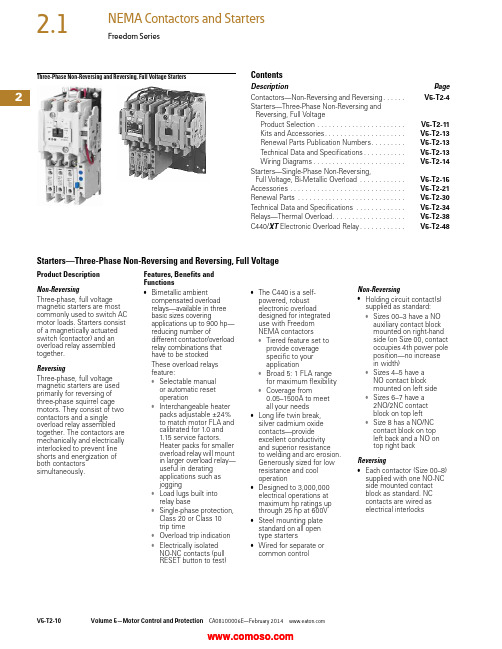
2Three-Phase Non-Reversing and Reversing, Full Voltage StartersContentsDescription PageContactors—Non-Reversing and Reversing. . . . . .V5-T2-4Starters—Three-Phase Non-Reversing andReversing, Full VoltageProduct Selection . . . . . . . . . . . . . . . . . . . . . . .V5-T2-11Kits and Accessories. . . . . . . . . . . . . . . . . . . . .V5-T2-13Renewal Parts Publication Numbers. . . . . . . . .V5-T2-13Technical Data and Specifications. . . . . . . . . . .V5-T2-13Wiring Diagrams. . . . . . . . . . . . . . . . . . . . . . . .V5-T2-14Starters—Single-Phase Non-Reversing,Full Voltage, Bi-Metallic Overload . . . . . . . . . . . .V5-T2-15Accessories . . . . . . . . . . . . . . . . . . . . . . . . . . . . . .V5-T2-21Renewal Parts . . . . . . . . . . . . . . . . . . . . . . . . . . . .V5-T2-30Technical Data and Specifications . . . . . . . . . . . . .V5-T2-34Relays—Thermal Overload. . . . . . . . . . . . . . . . . . .V5-T2-38C440/XT Electronic Overload Relay. . . . . . . . . . . .V5-T2-48Starters—Three-Phase Non-Reversing and Reversing, Full VoltageProduct DescriptionNon-ReversingThree-phase, full voltagemagnetic starters are mostcommonly used to switch ACmotor loads. Starters consistof a magnetically actuatedswitch (contactor) and anoverload relay assembledtogether.ReversingThree-phase, full voltagemagnetic starters are usedprimarily for reversing ofthree-phase squirrel cagemotors. They consist of twocontactors and a singleoverload relay assembledtogether. The contactors aremechanically and electricallyinterlocked to prevent lineshorts and energization ofboth contactorssimultaneously.Features, Benefits andFunctions●Bimetallic ambientcompensated overloadrelays—available in threebasic sizes coveringapplications up to 900 hp—reducing number ofdifferent contactor/overloadrelay combinations thathave to be stockedThese overload relaysfeature:●Selectable manualor automatic resetoperation●Interchangeable heaterpacks adjustable ±24%to match motor FLA andcalibrated for 1.0 and1.15 service factors.Heater packs for smalleroverload relay will mountin larger overload relay—useful in deratingapplications such asjogging●Load lugs built intorelay base●Single-phase protection,Class 20 or Class 10trip time●Overload trip indication●Electrically isolatedNO-NC contacts (pullRESET button to test)●The C440 is a self-powered, robustelectronic overloaddesigned for integrateduse with FreedomNEMA contactors●Tiered feature set toprovide coveragespecific to yourapplication●Broad 5: 1 FLA rangefor maximum flexibility●Coverage from0.05–1500A to meetall your needs●Long life twin break,silver cadmium oxidecontacts—provideexcellent conductivityand superior resistanceto welding and arc erosion.Generously sized for lowresistance and cooloperation●Designed to 3,000,000electrical operations atmaximum hp ratings upthrough 25 hp at 600V●Steel mounting platestandard on all opentype starters●Wired for separate orcommon controlNon-Reversing●Holding circuit contact(s)supplied as standard:●Sizes 00–3 have a NOauxiliary contact blockmounted on right-handside (on Size 00, contactoccupies 4th power poleposition—no increasein width)●Sizes 4–5 have aNO contact blockmounted on left side●Sizes 6–7 have a2NO/2NC contactblock on top left●Size 8 has a NO/NCcontact block on topleft back and a NO ontop right backReversing●Each contactor (Size 00–8)supplied with one NO-NCside mounted contactblock as standard. NCcontacts are wired aselectrical interlocks2Freedom SeriesProduct SelectionWhen Ordering Supply ●Catalog number ●Heater pack number (see selection table, Pages V5-T2-40 to V5-T2-42) or full load currentT ype AN16/AN56 NEMA—Manual or Automatic Reset Overload Relay—Non-Reversing and Reversing 1Magnet Coils—AC or DC Starter coils listed in this section also have a 50 Hz rating as shown in the adjacent table. Selectrequired starter by catalog number and replace themagnet coil alpha designation in the catalog number (_) with the proper code suffix from the table.For Sizes 00–2 and 5–8, the magnet coil alpha designation will be the next to last digit of the listed catalog number.EXAMPLE: For a 380V, 50 Hz coil, change AN16BN0_C to AN16BN0L C. For all other sizes, the magnet coil alpha designation will be the last digit of the listed catalog number.For DC Magnet Coils , see Accessories, Pages V5-T2-28 and V5-T2-29.AC SuffixNotes1Starter catalog numbers do not include heater packs. Select one carton of three heater packs. Heater pack selection, Pages V5-T2-40 to V5-T2-42.2Maximum horsepower rating of starters for 380V 50 Hz applications:3Underscore (_) indicates coil suffix required, see AC Suffix table.4The service-limit current ratings represent the maximum rms current, in amperes, which the controller shall be permitted to carry for protracted periods in normal service. At service-limit current ratings, temperature rises shall be permitted to exceed those obtained by testing the controller at its continuous current rating. The current rating of overload relays or trip current of other motor protective devices used shall not exceed the service-limit current rating of the controller.5Common control. For separate 120V control, insert letter D in 7th position of listed catalog number. Example: AN56VN D 0CB.6NEMA Sizes 00 and 0 only.7NEMA Sizes 00 and 0 only. Sizes 1–8 are 24/60 only.NEMA Size Continuous Ampere Rating Service-Limit Current Rating (Amperes) 4Maximum UL Horsepower 2Three-PoleNon-Reversing 3Three-Pole Reversing 3Vertical Reversing 3Single-Phase Three-Phase 115V 230V 208V 240V 480V 600V Catalog Number Catalog Number Catalog Number 009111/311-1/21-1/222AN16AN0_C AN56AN0_C —01821123355AN16BN0_CAN56BN0_C AN56BNV0_12732237-1/27-1/21010AN16DN0_B AN56DN0_B AN56DNV0_2455237-1/210152525AN16GN0_B AN56GN0_B AN56GNV0_390104——25305050AN16KN0_AN56KN0_AN56KNV0_4135156——4050100100AN16NN0_AN56NN0_AN56NNV0_5270311——75100200200AN16SN0_B AN56SN0_B —6540621——150200400400AN16TN0_C AN56TN0_C —7810932——200300600600AN16UN0_B AN56UN0_B —8 512151400——400450900900AN16VN0_BAN56VN0_B—Size 0Non-Reversing StarterSize 1Reversing StarterCoil Volts and Hertz Code Suffix Coil Volts and Hertz Code Suffix 120/60 or 110/50A 380–415/50L 240/60 or 220/50B 550/50N 480/60 or 440/50C 24/60, 24/50 7T 600/60 or 550/50D 24/50U 208/60E 32/50V 277/60H 48/60W 208–240/60 6J 48/50Y 240/50K48/50YNEMA Size 00012345678Horsepower1-1/25102550751503006009002Two-Speed Selective ControlWhen Ordering Supply●Catalog number plusmagnet coil code suffix.Example: Size 0—AN700BN022B●Heater pack number or fullload current for each speedFor two-speed other thanselective control:●Catalog number plusmagnet coil code suffix andoption required. Example:AN700BN022B exceptcompelling●Heater pack number or fullload current for each speedNote: Two-speed startersare designed for starting andcontrolling both separate(two-winding) and reconnectable(one-winding) motors. Separatewinding, WYE-WYE motorshave a separate winding foreach speed. Reconnectable,consequent pole motors use thesame winding for both speeds. Allstandard starters are wiredfor selective control.Separate Winding 1Reconnectable Winding 1Magnetic Coils—AC or DCNotes1 If branch circuit protective device is 45A or greater, C320FBR1 fuse kit(s) may be required for circuit protection per NEC 530-072.2 NEMA Sizes 00 and 0 only. Sizes 1–5 are 24/60 only.Maximum Horsepower—60/50 HertzNEMASizeOpen TypeCatalog Number Constant or Variable Torque Constant Horsepower115V200V230V460V/575V115V200V230V460/575V1-1/233512230AN700BN022_37-1/27-1/2102557-1/21AN700DN022_—101525—7-1/210202AN700GN022_—253050—2025403AN700KN022_—4050100—3040754AN700NN022_—75100200—60751505AN700SN022_Prices of starters do not include heater packs. Select two packs (two overload relays, one for each speed). Heater pack selection, Pages V5-T2-40 to V5-T2-42.Maximum Horsepower—60/50 HertzNEMASizeOpen TypeConstant or Variable Torque Constant HorsepowerConstant orVariable TorqueConstantHorsepower 115V200V230V460V/575V115V200V230V460/575V Catalog Number Catalog Number1-1/233512230AN700BN0218_AN700BN0219_37-1/27-1/2102557-1/21AN700DN0218_AN700DN0219_—101525—7-1/210202AN700GN0218_AN700GN0219_—253050—2025403AN700KN0218_AN700KN0219_—4050100—3040754AN700NN0218_AN700NN0219_Prices of starters do not include heater packs. Select two packs (two overload relays, one for each speed). Heater pack selection, Pages V5-T2-40 to V5-T2-42.Coil Voltage and Hz Code Suffix Coil Voltage and Hz Code Suffix Coil Voltage and Hz Code Suffix120/60 or 110/50A277/60H24/60, 24/50 2T240/60 or 220/50B208–240/60J24/50U480/60 or 440/50C240/50K32/50V600/60 or 550/50D380–415/50L48/60W208/60E550/50N48/50YTwo-WindingAN700DN022One-WindingAN700BN0218One-WindingAN700DN02182Freedom SeriesKits and Accessories●Auxiliary contacts, contactor mounted—Pages V5-T2-25 to V5-T2-27●Transient suppressor, for magnet coil—Page V5-T2-24●Timers—solid-state and pneumatic, mount on contactor—Page V5-T2-22Renewal PartsPublication Numbers●See Page V5-T2-30Technical Data and SpecificationsWire (75°C) Sizes—AWG or kcmil—NEMA Sizes 00–2—Open and EnclosedWire (75°C) Sizes—AWG or kcmil—NEMA Sizes 3–8—Open and EnclosedPlugging and Jogging Service Horsepower Ratings 3Notes1Minimum per NEC. Maximum wire size: Sizes 00 and 0 to 8 AWG and Sizes 1–2 to 2 AWG.2Two compartment box lug.3Maximum horsepower where operation is interrupted more than 5 times per minute, or more than 10 times in a 10 minute period. NEMA Standard ICS2-1993 table 2-4-3.NEMA SizeWire Size 1 Cu OnlyPower T erminals—Line 0012–16 AWG stranded, 12–14 AWG solid 08–16 AWG stranded, 10–14 AWG solid 18–14 AWG stranded or solid23–14 AWG (upper) and/or 6–14 AWG (lower) stranded or solid 2Power T erminals—Load—Cu Only (stranded or solid)00–014–6 AWG stranded or solid 1–214–2 AWG stranded or solidControl T erminals—Cu Only 12–16 AWG stranded, 12–14 AWG solidNEMA SizeWire Size 2Power T erminals—Line and Load 31/0–14 AWG Cu/Al4Open—3/0–8 AWG Cu; Enclosed—250 kcmil—6 AWG Cu/Al 5750 kcmil—2 AWG; or (2) 250 kcmil—3/0 AWG Cu/Al 6(2) 750 kcmil—3/0 AWG Cu/Al 7(3) 750 kcmil—3/0 AWG Cu/Al 8(4) 750 kcmil—1/0 AWG Cu/AlControl T erminals—Cu Only 12–16 AWG stranded, 12–14 AWG solidNEMA Size 200V 230V 460V 575V 00—1/21/21/201-1/21-1/2221335527-1/21015153152030304253060605607515015061251503003002Wiring DiagramsThree-Phase and Single-Phase Applications。
【推荐】无刷直流电机调速系统鲁棒性设计

专 业 推 荐↓精 品 文 档无刷直流电机调速系统鲁棒性设计魏海峰,李萍萍,包晓明,韩 彬(江苏大学电气信息工程学院,镇江 212013)摘 要:为提高无刷直流电机调速系统的鲁棒性,利用扰动观测器对外部负载转矩扰动进行估计并加以补偿,利用模糊自适应控制器实现P I D参数的在线自整定,以适应因系统内部参数变化引起的扰动。
仿真和实验表明,所设计的调速系统对系统负载扰动和参数变化的鲁棒性较好,并具有较高的速度跟踪精度。
关键词:无刷直流电机;鲁棒性;扰动观测器;模糊自适应控制;仿真;实验Robust ness D esi gn of Brushless DC M otor Speed Con trol Syste mW E I Hai2feng,L I Ping2p ing,BAO Xiao2m ing,HAN B in(School of Electrical and I nfor mati on Engineering,J iangsu University,Zhenjiang212013,China)Abstract:T o i m p r ove the r obustness of the brushless DC mot or contr ol syste m,a disturbance observer was p r oposed t o esti m ate and t o compensate the l oad disturbance.The para meters of P I D was modified aut omatically on line thr ough a fuzzy adap tive contr oller t o adap t the disturbance caused by the mot or pa2 ra meter uncertainty.Si m ulati on and experi m ental results verified that the p r oposed contr ol sche me showed r obust t o the l oad disturbance and mot or para meter uncertainty which i m p r oved the p recisi on of the s peed contr ol syste m.Key W ords:B rushless DC mot or;Robustness;D isturbance observer;Fuzzy adap tive contr ol;Si m u2 lati on;Ex peri m ent0 引 言由于转动惯量和相电阻的变化、电枢反应等因素,无刷直流电机是一种多变量强耦合的非线性系统,难以用精确的数学模型表达[122]。
ASUS ROG Rapture GT-AX11000 三带游戏路由器说明书

ROG Rapture GT-AX11000ROG Rapture Wireless-AX11000 Tri-band gaming router–World‘s first 10 Gigabit Wi-Fi router with quad-core processor and 2.5GBase-T Ethernet gaming port•Next-Gen Wi-Fi Standard –802.11ax Wi-Fistandard for better efficiency, throughput andrange.•Ultrafast Wi-Fi Speed –11000Mbps Wi-Fispeed to handle even the busiest networkwith ease.•Triple-level Game Acceleration –Accelerategame traffic every step of the way -fromdevice to game server.•Battle-ready-hardware –1.8GHz quad-coreCPU and 2.5GBase -T port for ultimateperformance.•Front-line Network Security –Neutralizeinternet threats before they hit your network.Next-Gen Ultra Fast Wi-Fi Standard,802.11AX–Speeds up to over10Gbps•Ultrafast Wi-Fi SpeedFeaturing 160MHz bandwidth and 1024-QAM for dramaticallyfaster wireless connections. With a total networking speed of about11000Mbps —1148Mbps on the 2.4GHz band and 4804Mbps onthe 5GHz-1 and 5GHz-2 band.•Better RangeWider coverage over large distances* of up to 80%1 due to thesmaller sub channels.•OFDMAOne channel can transmit data of several devices* at the same time,thus improving efficiency and reducing latency.•TWTTarget Wait Time allows transmissions to be scheduled, allowingdevices* to sleep for longer periods, delivering up to 7x betterbattery life.*To benefit from 802.11ax features, the Wi-Fi client needs to be 802.11ax capable•GT-AX11000 ROG Rapture Gaming Router•8 external detachable antennas •RJ-45 cable •Power adapter •Warranty card •Quick start guideWhat's Inside the Box•Wireless Type: 802.11 ax/ac/n/g/a/b •Wireless Speed: Up to 11000 Mbps •Wireless Frequency: Tri-band (2.4 & Dual 5 GHz)•I/O Port: 1 x 2.5G LAN Port, 1x 1G WAN Port, 4 x 1G LAN ports •USB : 2 x USB 3.0Specifications© 2016 ASUSTeK Computer Inc. All rights reserved.Specifications, content and product availability are all subject to change without notice and may differ from country to country. Actual performance may vary depending on applications, usage, environment and other factors. Full specifications are available at ROG Rapture GT-AX11000 supports Triple-level Game Accelerator to boost game traffic every step of the way, all the way from your devices to game server sides. Level 1, GameFirst V optimizes ROG devices. Gaming packets on these devices is given top priority, so your gaming packets are always at the head of the internet queue! Level 2, by turning on the GameBoost, all gaming packets are prioritized. With a physical Boost Key button built-in, users could select 1 of the features at their preference and for their convenience: DFS (Dynamic Frequency Selection) Bands on, GameBoost, or Aura Sync and LED on/off. Level 3, Gamers Private Network (by wtfast ®ensures that you connect via the shortest route between your network and the game server, for lowest ping and latency.Triple-level Game AcceleratorASUS Router App is built from the ground-up to be both intuitive and robust, allowing you to setup your router, manage network traffic, diagnose connection issues and even update firmware, all without needing to boot up a PC.Control Your Network Anywhere.ASUS Router App GameFirst V ConnectivityGT-AX11000 with GameBoost wtfast ®Connectivity IEEE 802.11a/b/g/n/ac, IEEE 802.11ax,IPv4, IPv6AX11000ultimate AX Performance: 1148+4804+4804Mbps Very large homes 802.11a : 6,9,12,18,24,36,48,54 Mbps802.11b : 1, 2, 5.5, 11 Mbps802.11g : 6,9,12,18,24,36,48,54 Mbps802.11n (1024 QAM) : up to 1000 Mbps802.11ac (1024 QAM) : up to 4333 Mbps802.11ax (2.4GHz) : up to 1148 Mbps802.11ax (5GHz) : up to 4804 MbpsExternal antenna x 8MIMO technology2.4 GHz 4x 45 GHz-1 4 x 45 GHz-2 4 x 4256 MB Flash1GB RAMWPA2-PSK, WPA-PSK, WPA-Enterprise ,WPA2-Enterprise , WPS supportFirewall :SPI intrusion detection, DoS protection Access control :Parental control, Network service filter, URL filter, Port filter UPnP, IGMP v1/v2/v3, DNS Proxy, DHCP, SNMP, NTP Client, DDNS, PortTrigger, Virtual Server, DMZ, System Event LogInternet connection type : Automatic IP, Static IP, PPPoE(MPPE supported),PPTP, L2TPBoost Key,WPS, Reset, Power, Wi-Fi on/off RJ45for 2.5GBase-T LAN x 1,RJ45 for 10/100/1000 BaseT for WAN x 1,RJ45 for 10/100/1000/Gigabits BaseT for LAN x 4USB 3.0 x 2© 2016 ASUSTeK Computer Inc. All rights reserved.Specifications, content and product availability are all subject to change without notice and may differ from country to country. Actual performance may vary depending on applications, usage, environment and other factors. Full specifications are available at Network StandardProduct SegmentCoverageData Rate AntennaTransmit/Receive Memory Encryption Firewall & AccessControl Management WAN Connection Type ButtonPortsConnectivityFeaturesLED Indicator Power Supply Dimensions WeightColorPackage Contents Operation mode ROG Gaming CenterLink AggregationSmart ConnectTraffic AnalyzerGame BoostAiProtection ProGamer Private Network®Game RadarWi-Fi RadarParental ControlGuest Network : 2.4 GHz x 3, 5 GHz-1 x 3, 5 GHz-2 x 3VPN server : IPSec Pass-Through, PPTP Pass-Through, L2TP Pass-Through,PPTP Server, OpenVPN ServerVPN client : PPTP client, L2TP client, OpenVPN clientMac OS BackupEnhanced media server (AiPlayer app compatible)-Image : Jpeg-Audio : mp3, wma, wav, pcm, mp4, lpcm, ogg-Video : asf, avi, divx, mpeg, mpg, ts, vob, wmv, mkv, movAiCloud personal cloud service3G/4G data sharingPrinter Server-Multifunctional printer support (Windows only)-LPR protocol supportDownload Master-Support bt, nzb, http, ed2k-Support encryption, DHT, PEX and magnet link-Upload and download bandwidth control-Download schedulingAiDisk file server-Samba and FTP server with account managementDual WANIPTV supportRoaming AssistPower x 1 / WAN x 1 / LAN x 4 / 2.5G Port x1/Wireless x 2 / USB x 1AC Input : 110V~240V(50~60Hz) / DC Output : 19 V with max. 3.42 A current 245 x 245 x 65 ~ mm (WxDxH)1880 gBlackGT-AX11000 ROG Rapture Gaming RouterRJ-45 CablePower AdapterQuick Start GuideWarranty CardWireless router mode, Access point mode, Media Bridge mode。
德鲁克 PACE 模块化压力控制器说明书

GEMeasurement & ControlPACE Modular Pressure ControllerA new generation of high precision Druck pressure controller, designed for test bench, bench top and rack mount calibration, and automated test applications.Modularity increases user fl exibility, reduces downtime and lowers overall cost of ownershipFeatures• Selection of Chassis and interchangeable control modules• Single, dual or auto range control module confi gurations• High speed pressure control• Up to 210 bar (3000 psi/21 MPa) gauge and absolute• P recision to 0.001% FS over calibrated temperature range• Accuracy 0.0016% Rdg (+0.0033% FS)• Long-term stability to 0.0025% FS per annum• Barometric reference option• U tilises GE’s new unique range of piezo-resistiveand TERPS pressure sensor technology• 28 selectable pressure units and 4 user defi ned units• S witch Test, Leak Test, Test Program, Burst Test, Analogueoutput and Volt Free Contact options• Aeronautical option• Negative gauge calibration included as standard• High resolution colour touch screen operation• Intuitive icon task driven menu structure• Compatible with software packages• RS232, IEEE connectivity, Ethernet and USB as standardPACE5000 Chassis • Single channel pressure controller chassis • Easy to use colour touch screen display • C an be used with any interchangeable PACE CM control module as a bench top or rack mounted pressure controller • I ntuitive task driven menu with basic, preset & divide as standard • S witch test, leak test, burst test, test program,analogue output and voltage free contacts available as optional tasks • M ulti Language - any additional language to suit speci fi c requirements can easily be translated & downloaded • RS232, IEEE connectivity, Ethernet and USB as standard• I nterchangeable robust control module that is easily installed into a PACE chassis • C alibration data stored in the control module (only the CM needs to be sent away for re-calibration)• High speed pressure control • Wide choice of pressure ranges• C hoice of standard, high, premium precision or reference accuracy pressure measurement • B arometric reference available to enable pseudo gauge/absolute indication & control • Aeronautical versionPACE6000 ChassisAdditional features:• Dual channel pressure controller chassis • W ith two PACE CM control modules fi tted the PACE6000 can be used in single, auto-ranging or simultaneous dual pressure control mode*• A eronautical option enabling full control in aeronautical units • No module pressure range ratio limit* for auto-ranging, both control modules have to be a range below 70 bar/1000 psi or both control modules have to be a range above 70 bar/1000 psiPACE Modular Pressure ControllerThe new PACE pneumatic modular pressure controller brings together the latest control and measurement technology from GE to offer an elegant, fast, fl exible and economical solution to pressure control for automated production, test and calibration.PACE employs full digital control to provide high control stability and high slew rate, while its digitally characterized pressure sensor offers the quality, stability, higher bandwidth and precision associated with this latest generation of piezo-resistive and TERPS devices.PACE CM – High Speed Pressure Control ModuleSwitch TestSwitch Test automates the testing of pressure switch devices. Following the test, the pressure at which contacts open and close and the switch hysteresis is displayed. Switch Test Task can also be set to repeat several times to exercise a switch or capture switch toggle max, min and average values.Leak TestLeak Test applies a test pressure(s) to an external system connected to the instrument to determine the magnitude of pressure variations due to leaks. This application sets the test pressure and a dwell time to eliminate potential adiabatic effects at the test pressure and the leak test time period. On completion, the display shows the Start Pressure, End Pressure, Pressure Change and Leak Rate.Test ProgramThe Test Program option provides a facility for creating, storing and executing numerous test procedures within the instrument itself. This is particularly useful for longer, more repetitive and laborious procedures requiring manual inputs for rapid prototyping, manufacturing and life cycle testing. Test Programs can also be transferred to a PC using a mass storage device for further editing, and copied back from the mass storage device to the instrument.Burst TestBurst Test is an application for the PACE Series designed primarily for the testing of pressure rupture discs.The burst test option applies a controlled increase of pressure and accurately measures the exact point at which the device rupture or burst occurs.Volt Free Contacts (VFC)Volt Free Contacts enable control of peripheral devices such as vacuum pumps, ovens, etc. Each VFC option has three independent volt-free NO/NC relay contacts.A number of conditions can be set within a PACE instrument to trigger a relay toggling its contacts. Analogue OutputThe analogue output can be programmed via the setup menu screen to output a signal proportional to the instrument range selected. This allows the instrument to interface with PC or PLC I/O cards, remote displays, chart recorders or other data logging equipment. Users can select outputs of 0 to 10 V, 0 to 5 V, -5 to5 V and 0/4 to 20 mA. Precision with respect to host instrument measured pressure 0.05% FS over the host instrument operating temperature range, variable update rate to 80 readings per second. The option is programmable between minimum and FS pressure forproportional output against pressure. Aeronautical Option (PACE6000 only, to beused with PACE CM2-A control modules) Simultaneous control of calibrated airspeed and altitude (when used with two PACE CM2-A control modules) with a “go to ground” function.Indication and control available in pure aeronautical units:Altitude - feet or metersAir Speed - knots or km/hour, mphMach - mach numberRate of climb – feet or meters/minute, secondPACE5000/6000 OptionsSpecifications1. PACE ChassisPACE5000 Single Channel Chassis - I5000 Chassis PACE6000 Dual Channel Chassis - I6000 Chassis2. PACE Chassis - OptionsThe range of optional features includes:• S witch Test – Automatic & accurate calibration of pressure switches• L eak Test – Automatically measures leak rates in the desired units/minute or units/second• Test Program – Write & save numerous testprograms• Burst Test – For testing the pressure rupture point • A nalogue Output – for integration into older ATE applications• V olt Free Contacts – For automatically triggering ancillary devices• A eronautical (PACE6000 only) - Allows for the test and calibration of aeronautical instruments3. PACE Chassis - Mains LeadChoose one from this list:MAINS LEAD IEC-UK PLUGMAINS LEAD IEC-JAPAN PLUGMAINS LEAD IEC-EU PLUGMAINS LEAD IEC-USA PLUGMAINS LEAD IEC-SOUTH AFRICA/INDIA PLUGMAINS LEAD IEC-CHINA PLUGMAINS LEAD IEC-Australia/New Zealand PLUGArea of UsePlease state area of use for instrument set up:EuropeNorth AmericaJapanAsiaRest of World4. PACE Control Module - Precision PACE CM0 = StandardPACE CM1 = HighPACE CM2 = PremiumPACE CM3 = Reference5. PACE Control Module - Pressure Range6. PACE Control Module - Barometric OptionProvides absolute pressure option in addition to gauge pressure. In absolute mode adds barometric pressureto gauge pressure range. Pressure control in absolute range is not available for any CM0-B/CM1-B/CM2-B with a gauge range of 700 mbar (10 psi, 70 kPa) or below.• PACE CM0-B = Standard• PACE CM1-B = High• PACE CM2–B = PremiumProvides gauge pressure option in addition to absolute pressure. In gauge mode, subtracts barametric pressure from absolute pressure range.Not available for pressure ranges less than 2 bar(30 psi, 200 kPa) absolute.• PACE CM3-B = Reference7. PACE Control Module – PACE6000 Aeronautical OptionPACE CM2-A = -3000 to + 55,000 ft (Altitude)PACE CM2-A = to 650 knots (Airspeed with true mach)Ordering Information Please state the following (where applicable)8. Physical Accessories920-561E © 2016 General Electric Company. All Rights Reserved. Specifi cations are subject to change without notice. GE is a registered trademark of General Electric Company. Other company or product names mentioned in this document may be trademarks or registered trademarks of their respective companies, which are not affi liated with GE.。
Robust Control and Estimation
Robust Control and Estimation Robust control and estimation are essential concepts in the field of engineering, particularly in the design and implementation of control systems for various applications. These concepts play a crucial role in ensuring the stability, performance, and reliability of control systems in the presence of uncertainties and disturbances. In this response, I will delve into the significance of robust control and estimation, their applications, challenges, and future prospects.First and foremost, robust control and estimation techniques are designed to address the inherent uncertainties and variations that exist in real-world systems. These uncertainties can arise from various sources such as parameter variations, external disturbances, sensor noise, and modeling errors. Robust controltechniques aim to ensure that the system remains stable and performssatisfactorily despite these uncertainties. This is achieved by designing control laws that are able to accommodate a wide range of system variations, thusproviding a robust performance across different operating conditions. In addition to robust control, robust estimation techniques are also crucial in the design of control systems. Estimation techniques such as Kalman filtering and robust observers play a key role in providing accurate and reliable estimates of the system states and parameters, which are essential for feedback control. These techniques are particularly important in applications such as aerospace, automotive, and robotics, where precise state estimation is critical for theoverall system performance. Moreover, the applications of robust control and estimation are diverse and widespread. In the aerospace industry, for example, robust control techniques are used to design flight control systems that canhandle uncertainties in aircraft dynamics and environmental disturbances. Similarly, in the field of robotics, robust estimation techniques are employed to accurately estimate the position and orientation of robotic manipulators, enabling precise and reliable control of their movements. Furthermore, in industrial automation, robust control techniques are utilized to ensure the stability and performance of various processes, such as chemical reactors and power plants, in the presence of uncertainties and disturbances. Despite their significance,robust control and estimation techniques also present several challenges. One ofthe major challenges is the trade-off between performance and robustness. Designing control laws that are robust to uncertainties often involves sacrificing some level of performance, such as speed of response or control effort. Finding the right balance between performance and robustness is a complex and non-trivial task, requiring careful consideration of the specific requirements and constraints of the application. Another challenge is the computational complexity associated with robust control and estimation techniques. Many of these techniques involve solving optimization problems or performing real-time state estimation, which can be computationally intensive, especially for high-dimensional systems. This necessitates the development of efficient algorithms and hardware implementations to enable real-time deployment of robust control and estimation techniques in practical applications. Looking ahead, the future prospects of robust control and estimation are promising, driven by advancements in technology and research. The emergence of machine learning and data-driven approaches has the potential to enhance the robustness and performance of control systems by leveraging large volumes of data to adaptively learn and account for uncertainties. Additionally, the integration of advanced sensing and actuation technologies, such asdistributed sensors and actuators, can further improve the robustness andreliability of control systems by providing more comprehensive information about the system and its environment. In conclusion, robust control and estimation are indispensable concepts in the field of engineering, with wide-ranging applications and significant challenges. The continued research and development in this area hold the promise of enabling more robust, reliable, and high-performance control systems across various domains. By addressing the uncertainties and disturbances inherent in real-world systems, robust control and estimation techniques play a critical role in advancing the state-of-the-art in engineering and technology.。
基于终端滑模控制器的高精度伺服系统设计
基于终端滑模控制器的高精度伺服系统设计Design of high precision servo system based on terminal sliding mode controller王朝阳,潘松峰WANG Zhao-yang, PAN Song-feng(青岛大学 自动化学院,青岛 266000)摘 要:随着工业机器人与精密机床的发展,传统的三环控制策略无法满足伺服系统对动态响应速度、位置跟踪精度及超调量越来越高的要求。
针对这一问题,结合已有的研究成果,提出微分前馈控制与终端滑模结合的控制策略,在负反馈基础上,添加位置前馈控制,实现位置信号的快速跟踪,将非奇异快速终端滑模控制方法应用到位置环与速度环,提高电机位置跟踪精度以及在电机出现较大位置误差时减小超调量。
理论分析和仿真验证算法的可行性和有效性。
关键词:永磁同步电机;位置伺服系统;终端滑模控制;前馈控制中图分类号:TP273 文献标识码:A 文章编号:1009-0134(2021)01-0113-05收稿日期:2019-10-20作者简介:王朝阳(1996 -),男,山东德州人,硕士研究生,研究方向为电机控制。
0 引言在工业机器人以及精密机床中的伺服系统要求较高的位置跟踪精度,同时位置伺服系统经常会出现阶跃的位置信号或者发生较大的位置误差,出现这种瞬时脉冲信号时无法避免出现较大的超调量,而位置环存在超调量的一部分原因是速度环抑制速度波动以及抗负载变化的能力弱。
这使传统的控制方法难以同时满足这两个要求。
文献[1~3]将滑模控制应用于伺服系统位置和速度环,通过对伺服系统滑模面及控制律的合理设计,较好地实现了位置精确定位;文献[4]将终端滑模控制方法应用于PMSM 的调速系统中,但用于位置伺服系统中时,系统位置跟踪精度较差需要改进位置环,同时添加位置前馈控制时,接收前馈补偿信号的速度环在采用滑模控制时也需要进行改进;文献[5]针对伺服系统的高精度位置控制问题,提出了基于自适应模糊补偿器的终端滑模控制方法;文献[6]将终端滑模控制应用到伺服系统的电流环、速度环和位置环中,系统具有较高的跟踪精度和较小的超调量;文献[7,8]将前馈控制应用于PMSM 位置伺服系统,将位置前馈补偿信号作用在速度环,在速度环使用PI 控制,系统跟踪误差小,但抑制速度波动以及抗负载变化的能力弱,超调量较大。
Robust Control

Robust ControlRobust control is a crucial aspect of engineering and technology that focuses on designing systems that can perform effectively in the presence of uncertainties and variations. It is essential for ensuring stability and performance in a wide range of applications, from aerospace and automotive systems to industrial processes and robotics. Robust control techniques aim to account for uncertainties in the system model, disturbances, and variations in operating conditions, to ensure that the system can still meet its performance requirements. One of thekey challenges in robust control is dealing with uncertainties in the system model. In many real-world applications, it is difficult to obtain an accurate model ofthe system dynamics, and there may be uncertainties in parameters or disturbances that affect the system's behavior. Robust control techniques address thischallenge by designing controllers that can guarantee stability and performance even in the presence of these uncertainties. This is typically done by formulating the control problem as an optimization problem, where the goal is to find a controller that minimizes the impact of uncertainties on the system's performance. Another important aspect of robust control is ensuring stability of the system. Stability is a fundamental requirement for any control system, as an unstable system can lead to catastrophic failures and safety hazards. Robust control techniques often involve analyzing the system's stability properties and designing controllers that can ensure stability under a wide range of operating conditions. This may involve using robust stability analysis tools, such as the small gain theorem or the circle criterion, to assess the system's stability margins and ensure that the controller can stabilize the system in the presence of uncertainties. In addition to stability, robust control also aims to achieve good performance in terms of tracking accuracy, disturbance rejection, and robustnessto variations in operating conditions. Performance requirements can vary depending on the specific application, but common objectives include minimizing tracking errors, reducing the impact of disturbances, and ensuring that the system can maintain its performance even in the presence of variations in parameters or operating conditions. Robust control techniques often involve designingcontrollers that can achieve these performance objectives while also ensuringstability and robustness. Robust control techniques have been widely used in a variety of applications, ranging from aerospace and automotive systems toindustrial processes and robotics. In aerospace applications, for example, robust control is essential for ensuring the stability and performance of aircraft and spacecraft in the presence of uncertainties in aerodynamic forces, engine dynamics, and environmental conditions. In automotive systems, robust control is used to design controllers for vehicle stability control, adaptive cruise control, andanti-lock braking systems, to ensure safe and reliable operation under varyingroad conditions. Overall, robust control plays a critical role in ensuring the stability, performance, and safety of complex engineering systems. By accountingfor uncertainties and variations in system dynamics, robust control techniques enable engineers to design controllers that can effectively regulate the system's behavior and meet its performance requirements. As technology continues to advance and systems become more complex, robust control will remain a key area of research and development, helping to drive innovation and progress in a wide range of industries.。
- 1、下载文档前请自行甄别文档内容的完整性,平台不提供额外的编辑、内容补充、找答案等附加服务。
- 2、"仅部分预览"的文档,不可在线预览部分如存在完整性等问题,可反馈申请退款(可完整预览的文档不适用该条件!)。
- 3、如文档侵犯您的权益,请联系客服反馈,我们会尽快为您处理(人工客服工作时间:9:00-18:30)。
Robust Speed Control of Induction Motor Drives Using First-Order Auto-DisturbanceRejection ControllersJie Li,Hai-Peng Ren,Member,IEEE,and Yan-Ru ZhongAbstract—A novel robust control scheme employing three first-order auto-disturbance rejection controllers(ADRCs)is pre-sented for the speed control of induction motor pared with the existing high-order ADRC-based speed control struc-tures,the proposed method does not need to estimate the rotor flux.As a result,the implementation of the proposed scheme on a digital signal processor(DSP)is easier,and the runtime of the proposed ADRC control algorithm is shorter.The simulation results show that the proposed control scheme can cope with the internal disturbance and external disturbance,such as the motor’s parameter variations,the load disturbances,etc.A TMS320F2812 DSP-based prototype using the proposed control scheme was developed.The comparative experimental results show that the robustness of the proposed ADRC system is obviously better than the conventional proportional–integral system when various disturbances occur,and the scheme is feasible and effective.Index Terms—Auto-disturbance rejection controller(ADRC), induction motor,robust control,vector control.I.I NTRODUCTIONI NDUCTION motors can be controlled similarly as dc mo-tors using thefield-oriented control(FOC)(also called vector control)approach,and the performances of the con-trolled induction motors with FOC are comparable to those of the dc motors.With the development of the power elec-tronics elements and the high-performance microprocessor, induction motor drives employing FOC and conventional proportional–integral(PI)regulators have been commercial-ized.However,the performances of the PI regulator-based FOC suffers from the induction motor parameters’mismatch orManuscript received June22,2013;revised December1,2013and February27,2014;accepted May7,2014.Date of publication June10,2014; date of current version January16,2015.Paper2013-IACC-539.R2,pre-sented at the2012IEEE Industry Applications Society Annual Meeting, Las Vegas,NV,USA,October7–11,and approved for publication in the IEEE T RANSACTIONS ON I NDUSTRY A PPLICATIONS by the Industrial Automation and Control Committee of the IEEE Industry Applications Society.This work was supported in part by the National Natural Science Foundation of China under Grant50907054,in part by the Specialized Research Fund for the Doctoral Program under Grant20126118110008,in part by the Innovation Research Team of Shaanxi Province under Grant2013KCT-04,in part by the Natural Science Research Project of Educational Affairs Committee of Shaanxi Province under Grant2013JK0995,in part by the Scientific Research of Inter-national Cooperation Project of Shaanxi Province under Grant2013KW05-02, and in part by the Scientific Fund of Key Discipline of Shaanxi Province under Grant105-5X1301.The authors are with the School of Automation and Information Engineer-ing,Xi’an University of Technology,Xi’an710048,China(e-mail:lijie@ ;renhaipeng@;zhongyr@).Digital Object Identifier10.1109/TIA.2014.2330062variation with time[1].In addition,when the load disturbances are present,the PI controller scheme has a long recovery period. Generally speaking,the requirements of the motor speed control system are the accuracy,the rapidity,the robustness, and so on.To satisfy these performance requirements of the industry drive system,electrical engineers use two ways:one way is using the online parameter identification to estimate the corresponding parameters in the FOC;and the other way is us-ing the robust controller to replace the conventional PI regulator to get better performance.During the past few decades,many online parameter identification methods have been proposed for FOC[2].However,the parameters of the system are inherently dependent on each other.As a result,more parameters are needed to be identified,which increases the complexity of the algorithm and the difficulty of real-time applications.In order to directly aim at the original goal,i.e.,to improve the control per-formances of the drive systems,researchers attempted various kinds of robust controllers to cope with the parameter uncer-tainty,and at the same time,not to degrade the accuracy and the rapidity of the speed control.For example,an adaptive robust control strategy was proposed in[3]to increase robustness to parameter variations and load disturbance for sensorlessfield-oriented controlled induction motor drives.A back-stepping controller based on the exact model of the induction motors was proposed in[4].Meanwhile,the extended state observer(ESO) was employed to improve the robustness to the uncertainty of the system.The neural network-based robust control schemes were proposed to obtain a robust speed control of induction motor drives in[5]and[6].The ADRC was proposed by Han in1998[7]–[9].The ADRC is a nonlinear controller for an uncertain system,it estimates and compensates the external disturbances and pa-rameter variations,and as a consequence,the accurate model of the plant is not required.It means that the design of ADRC is inherently independent of the controlled system model and its parameters.Bogdan M.Wilamowski,former Editor-in-Chief of the IEEE T RANSACTIONS ON I NDUSTRIAL E LECTRONICS, pointed out that“ADRC turns modern control theory on its head.The implication of this change of direction proved to be enormous both in theory and practice”[9].As one of the simple robust control methods to deal with the uncertainty,ADRC attracts much attention in many technical fields[10]–[25],particularly in thefield of the motor control [14]–[25].A second-order ADRCs was proposed for the speed control of the brushless dc motor[14],[15].ADRC was used for0093-9994©2014IEEE.Personal use is permitted,but republication/redistribution requires IEEE permission.See /publications_standards/publications/rights/index.html for more information.direct torque control of permanent-magnet synchronous servo motor[16].Aside from speed control,ADRC was also applied to speed estimation to improve the robustness of the estimation algorithms[17].Many ADRC-based research works have been done to im-prove the robustness of the induction motor speed control[18]–[25].The ADRC-based speed control scheme for the induction motor drives has the advantage of good robustness to parameter uncertainty and external disturbance.Thefirst scheme of speed control of the induction motor based on ADRC was proposed in[18]and applied in[19]–[21].In this scheme,twofirst-order ADRCs were used to control the rotor speed and the quadrature component of the stator current,respectively,and one second-order ADRC was used to regulate the rotorflux.A four-ADRC configuration was proposed for the speed control of the induction motor fed by a matrix converter[22].Two second-order ADRCs were used to regulate the rotor speed and the quadrature component of the stator current,respectively,and one third-order ADRC was used to regulate the rotorflux in [23]to achieve robust speed control of induction motor.Two second-order ADRCs were employed for the speed and rotor flux control of the induction motor[24].Two conventional PI regulators were used for the torque current and magnetizing current control;meanwhile,two second-order ADRCs were used for speed control[25].Most of the aforementioned works on induction motor con-trol are limited to simulation results.All these existing schemes using ADRCs require the estimation of the rotorflux;therefore, the real-time computing cost is increased when the algorithms are implemented on digital signal processors(DSPs).Further-more,the existing works usually use the second-order(or third-order)ADRCs,including the third-order(or fourth-order) dynamical equations for ESO.Consequently,the complexity of the entire control algorithm is dramatically increased.In this paper,a novel control scheme based on three first-order ADRCs is presented.The rotorflux estimation is removed to reduce the runtime of the proposed ADRC control algorithm.Because the order of ADRC is low and theflux estimation is removed,the DSP code implementation of the proposed method is easier,and the code running time is shorter as well.Simulation results show that the proposed simplified ADRC robust speed control scheme provides strong ability to resist the uncertainties,such as external load disturbances and motor parameter variations.Experimental results also show the feasibility and effectiveness of the proposed method.This paper is organized as follows:the robust control scheme using threefirst-order ADRCs is given for induction motor speed control in Section II.The robust performances of the proposed scheme are tested by simulation in Section III.Exper-imental results on experimental bench are given in Section IV to show the effectiveness of the proposed method.Conclusion remarks are given in Section V.II.T HREE F IRST-O RDER ADRCS C LOSED-L OOP S PEEDC ONTROL OF I NDUCTION M OTORSFor the FOC scheme of induction motors,three control loops, including the quadrature axis(q-axis)current loop,the direct axis(d-axis)current loop,and the speed loop,are considered. Fig.1(a)shows an example of the induction motor speed control system using high-order ADRCs,which consists of two second-order ADRCs for the speed control and q-axis current control,respectively,and one third-order ADRC for the d-axis current control.Meanwhile,theflux estimator is needed to get the information aboutflux and rotor angle.Fig.1(b)gives the proposed scheme using threefirst-order ADRCs for the speed control of induction motors,where threefirst-order ADRCs are used for the three control loops of the system.It is shown from Fig.1that the proposed control scheme is simpler in the sense of using lower order ADRCs,which means the lower order of dynamical equation to be solved and that the removal of the flux estimator further reduces the complexity of the control algorithm.The proposed speed control scheme employs three different first-order ADRCs for rotor electrical angular speedωr regu-lation,direct component of stator current i d1regulation,and quadrature component of stator current i q1regulation.It means that the proposed control scheme use open loop control for the rotorflux.The motivation of using open loopflux control is to reduce the complexity of the control algorithm when it is implemented on DSP.As shown in Fig.2,eachfirst-order ADRC is composed of three parts:1)nonlinear differentiator(ND);2)ESO;and 3)nonlinear state error feedback control law(NLSEF).The ESO in the ADRC can be treated as a kind of dynamic feedback linearization mechanism.Its structure and performance are not only determined by the model of the system under control,but only by the range of its variation rate.Therefore,the ESO is robust to the system model uncertainty.The role of ND is to define a desirable transition response for the step input.The ND can smoothen the sudden change of the input signal in order to decrease the overshoot of the output response during the transient state.These factors make ADRC get a good balance between the fast transient response and the small overshoot.On the contrary,for the conventional PID controller,it is hard for tuning parameters to achieve this point.The NLSEF gives the control law u0to drive the state trajectory to track the desired reference.Now,we explain how to design the threefirst-order ADRCs as follows.A.ADRC for Speed RegulationThe mathematical model of the speed control loop is˙ωr=k1ψd2i q1+w1(t)(1) wherek1=P2L m/JL2and w1(t)=−P T L/JΨd2is the d-axis rotorflux linkage,i q1is the q-axis stator current,P is the number of pole pairs of the motor,J is the rotor inertia,L m is the mutual inductance,L2is the rotor inductance, and T L is the load torque.The load torque T L and the coupling term between the speed loop andflux loop can be treated as the“disturbances”when weparison of the scheme using higher order ADRC and our proposed scheme.(a)Example of control systems using high-order ADRCs.(b)Proposed scheme based on three first-orderADRCs.Fig.2.Block diagram of first-order ADRC.design the ADRC for the speed loop.These disturbances can be compensated by the ESO given as ⎧⎪⎨⎪⎩e (k )=z 1(k )−y (k )z 1(k +1)=z 1(k )+h (z 2(k )−β1fal (e (k ),α1,δ1)+bu (k ))z 2(k +1)=z 2(k )−hβ2fal (e (k ),α1,δ1)(2)where function fal (e (k ),α,δ)is a nonlinear function given asfal (e (k ),α,δ)=|e (k )|αsgn (e (k )),|e (k )|>δe (k )/δ1−α,|e (k )|≤δand y (k )is the output signal of the system (plant)to be controlled.For the speed loop,y (k )is the speed ωr (as shown in Fig.1),z 1(k )is the estimation of the system state,z 2(k )is the estimation of the disturbances.ESO has four adjustableparameters:α1,δ1,β1,and β2.The range of α1is from 0to 1;the smaller the α1is,the better the ability of the ESO against the uncertainty of the induction motor model and the disturbances is.δ1is the width of linear area of the nonlinear function.The system dynamic performances are affected tremendously by the β1and β2.β1mainly has effect on the estimation of the system state,and β2mainly affects the estimation of the disturbances.The larger the β1and the β2are,the faster the estimation converges,on the other hand,if the β1and the β2are too large,the estimation might not converge.The ND is given asx 1(k +1)=x 1(k )+hx 2(k )x 2(k +1)=x 2(k )+hfst (x 1(k )−v (k ),x 2(k ),r,h 0)(3)where the nonlinear function can be represented byfst (p 1(k ),p 2(k ),r,h 0)=−ra (k )/d,|a (k )|≤dr sgn (a (k )),|a (k )|>dy td (k )=p 1(k )+h 0p 2(k ),a 0(k )= d 2+8r |y td (k )| 12a (k )=p 2(k )+(a 0(k )−d )/2,|y td (k )|>d 0p 2(k )+y td (k )/h 0,|y td (k )|≤d 0d =rh 0,d 0=dh 0v(k)is the reference signal of the ADRC,for the speed loop, v(k)is the speed referenceω∗r(as shown in Fig.1),x1(k)is the tracking signal of v(k),x2(k)is the derivative of x1(k), also approximately the derivative of v(k),h is the step size. ND is used to arrange transition procedure when tracking the reference signal.There are two adjustable parameters in the ND,i.e.,r and h0.r is the convergence rate coefficient. The larger the r is,the faster the procedure that x1(k)converges toω∗r is.h0is afiltering factor used for the noisefiltering. According to the output of the ND and the ESO,the NLSEF gives the control to the corresponding loop⎧⎨⎩e1(k)=x1(k)−z1(k)u0(k)=β3fal(e1(k),α2,δ3)u(k)=u0(k)−z2(k)/b(4)where u(k)is the control output of the ADRC,for the speed loop,u(k)is the q-axis stator current reference i∗q1(as shown in Fig.1).α2andδ3possess the similar meanings as that of α1andδ1in(2).β3governs the speed of the system response, however,ifβ3is too large,a big overshoot would appear.B.ADRC for q-Axis Current LoopThe mathematical model of the q-axis stator current is˙iq1=−k2i q1+w2(t)+u q1/Lσ(5)wherek2=R1L22+R2L2m/LσL22w2(t)=−L mψd2ωr/LσL2−i d1ω1Lσ=L1−L2m/L2and u q1is the q-axis stator voltage.R1and R2are the stator resistance and rotor resistance,respectively.L1is the stator inductance,Lσis leakage inductance.ωr is rotor angular speed.ω1is synchronous angular speed.It can be seen from(5)that the“disturbance”w2(t)contains the coupling terms,i.e.,the product of the rotorfluxΨd2 and the rotor angular speedωr,and the product of the d-axis stator current i d1and synchronous angular speedω1.If a PID controller was used,the performances of the system will be degraded because of this nonlinear coupling terms.However, the ADRC can estimate the disturbance and cope with the effect of this coupling term to get better performance.The ADRC used in the q-axis current loop is similar to that of the speed-loop ADRC,except the input and output shown in Fig.1(b). C.ADRC for d-Axis Current LoopThe mathematical model of the d-axis stator current control loop is˙id1=−k2i d1+w3(t)+u d1/Lσ(6) wherew3(t)=k3ψd2+i q1ω1k3=R2L m/LσL22i d1is the d-axis stator current,and u d1is d-axis stator voltage. Here,w3(t)is treated as disturbance,which contains the coupling term,i.e.,the product of the synchronous angular speedω1and the q-axis stator current i q1.The rotor resistance is also considered in the disturbance,and it is subjected to the variations of operation conditions of induction motors. ADRC can automatically estimate all these disturbances and compensate them to achieve better performance.The ADRC for d-axis current loop is designed using the similar way as that in the speed loop,which is omitted for simplicity.III.S IMULATION R ESULTSTo show the performance of the proposed control scheme, an MATLAB/Simulink model[26]has been established for a 1.1-kW induction machine driven by a voltage source inverter (VSI)using the proposed scheme.Eachfirst-order ADRC is written by an S-function with C code.The parameters of the squirrel-cage induction motor are listed as follows:P N=1.1kWU N=380VI N=2.67Af N=50HzR1=5.27ΩR2=5.07ΩR Fe=1370ΩL1=479mHL2=479mHL m=421mHσ=0.228T N=7.45N·mP=2n N=1410r/min.We have investigated the robustness of the proposed scheme under the following three cases a)load disturbance;b)the motor parameter variations;and c)the model uncertainty.The proposed method is compared with the vector control based on the traditional PI regulators.In the simulation,both the adjustable parameters of the ADRC and those of the PI system have been manually tuned to their desirable values.It can be also done by the method proposed in[15].A.Load Disturbance PerformanceFig.3shows the comparative simulation results when the load torque disturbance occurs,Fig.3(a)shows the speed response when the load torque steps up from no load to the rated load(1pu)at1.5s,and Fig.3(b)shows the speed response when the load torque steps down from the rated load to no load at3s.In Fig.3,the speed reference is1300r/min, The motor parameters are constant during the simulations.As shown in Fig.3,in the steady-state performance aspect,the ADRC system can always settle down to the speed referenceparative simulation result when load torque disturbances occur with speed reference is1300r/min.(a)Load torque steps up from no load to the rated load at1.5s.(b)Load torque steps down from the rated load to no load at3s.value without steady-state error,whereas the steady-state error of the PI system increases when the load is heavier,even up to1.3%under rated load.This shows that the ADRC system has better robustness compared with the PI System from the viewpoint of load disturbances.In the dynamic performance aspect,the ADRC system always has larger overshoot than the PI system in the simulation results,the reason is that their linearization mechanisms are essentially different:the PI regulator depends on thefield oriented to realize the decoupling of the torque control and theflux control,when the rotorflux direction coincides with the d-axis,under this circumstance,the induction motor can be treated as a“linear”system.However,in ADRC control scheme,the ESO,a core component of ADRC, estimate the internal and the external disturbances as the“total disturbance”in real time,then compensate it.As a result,the system is dynamically linearized.In a simulation model, the PI system uses the exact parameters,which means that the parameters used in the vector control scheme match very well with the motor;thus,the dynamic performance could be perfect if the parameters of the PI regulators are optimized.On the contrary,the dynamic performance of the ADRC depends on the dynamic performance of its ESO,when the load suddenly increases or decreases,the disturbances in(1),(5),and(6)of the three ADRCs will also suddenly change,the ESOs will undergo a transient state to estimate the disturbance and to track reference.Therefore,even if the ADRC parameters are good,the simulation results will inevitably overshoot when load torque steps up or down heavily in high speed range.In practice,the experimental results in Section IV show that when load torque steps up or down,the PI system alsoparative simulation result when rotor resistance steps up and down.shoot because of inexact parameters used in the PI controller, i.e.,the parameter mismatch.B.Parameter Variation PerformanceTo evaluate the rapidity and the accuracy of control algo-rithms,the step response of reference variation or the step response of disturbance is usually observed,because the step signal contains the most abundant frequency components.For induction motor drive systems,if wound-rotor induction motors were selected,the rotor resistance may suddenly increase or decrease.Although,the rapid parameter variation is not the gen-eral case,the step variation of the rotor resistance is still chosen here to do the comparative simulation,in order to evaluate the proposed ADRC scheme under the worst operation condition.A simulation motor model[26]with a varying rotor re-sistance is used to simulate the performance of the proposed scheme.Fig.4shows the comparative simulation results when the motor parameter varies.The solid line,i.e.,the smoother one, is the speed response of the proposed ADRC scheme,and the dash line,i.e.,the oscillating one,is the speed response of the conventional PI controller.The operation condition is the same for both controllers,i.e.,the speed reference is1pu,and the load torque is1pu.The motor parameters are given as the foregoing parameter list.The rotor resistance steps up from1to 1.5pu at4s and down to1pu again at6s.In fact,it is almost impossible in the practical situation that the rotor resistances suddenly increase or decrease for the squirrel-cage induction motor.However,for the purpose of evaluating the robustness, step changes of the rotor resistance is chosen in simulation.As shown in Fig.4,when the rotor resistance suddenly changes, the proposed scheme is more robust than the conventional PI control.The ADRC system is able to quickly complete the adjustment process and stabilize at the reference speed again, whereas the PI control demonstrates a speed oscillation when the motor parameter parative simulations under the conditions that other motor parameters change have been done.The conclusion is that the ADRC is more robust than the PI control when the motor parameters change.C.Model Uncertainty PerformanceThe motor model considering the iron loss[26]is used to simulate the model uncertainty[19].Both PI controller and theparative simulation result when modeling error exists. proposed ADRC(s)are designed according to the ideal motor model(i.e.,without considering the impact of the nonideal factors such as magnetic saturation and iron loss).In fact,an actual motor cannot behave as we expect;thus,the electrical engineers have to use more robust control methods to get the desirable performance under the undesirable condition.Fig.5shows the comparative simulation results when the iron loss exists in the model,whereas the controller design procedure did not take into account.The solid line is the response of the proposed scheme,and the dashed line is the PI system.The operation condition is same for both schemes,i.e., the speed reference steps up from0.4to0.8pu at5s,and the load torque is full load throughout the simulation.The motor parameters,including the iron loss equivalent resistance,are set as the parameters listed aforementioned.If theflux control and the torque control of the induction motor are completely decoupled,the q-axis component rotorflux should be zero at the steady state.As shown in Fig.5,both the ADRC and the PI control do not make the q-axis component rotorflux to be zero, but the steady-state error of the q-axis rotorflux of the ADRC is obviously less than that of the PI control.It means that the decoupling degree of the proposed scheme is better than that of PI control.IV.E XPERIMENTAL R ESULTSThe experimental bench(see Fig.6)is built based on the core of TMS320F2812DSP,the actual motor has the same nominal parameters as that used in the simulations.The ADRC algorithm was written in mixed C language and assembly language in order to improve the execution speed,the execution time of each ADRC is about50μs.The sampling periods of the current loops and the speed loop are250μs,so that the code for ADRC can be executed in real time.Compared with the conventional PI regulators,the ADRCs have more parameters to be tuned.However,once these param-eters are set appropriately,it is effective all over the speed range and load condition.For the conventional PI systems,it always need several proportion coefficient and integral coefficient sets to obtain the desired speed control performance in different speed ranges for the same induction motor.From this point of view,the ADRC also has its superiority.On the other hand,some parameters in the ADRCs have their empirical values,e.g.,α1,α2,h0etc.;thus,the tuning procedure of the ADRC parameters is easier than our imagination.Using Fig.6.Photograph of the experimentalbench.parative experimental results when load torque disturbance occurs (speed reference is1300r/min,load torque steps down from rated load to no load,(a)ADRC system and(b)PI system).the trial and error method,the ADRCs parameters are set as follows.1)Speed ADRC controllerTD:r=60,h0=0.01ESO:α1=0.5,δ1=0.2,β1=20,β2=400,b0=11 NLSEF:β3=10,δ2=0.2,α2=0.75.2)q-axis current loop ADRC controllerTD:r=400,h0=0.01ESO:α1=0.5,δ1=10,β1=10,β2=600,b0=300 NLSEF:β3=10,δ2=10,α2=0.75.Fig.8.Controlled experimental result when load torque disturbance occurs (speed reference is1000r/min,and load torque steps up from no load to0.8-pu load,(a)the proposed scheme and(b)conventional PI control).3)d-axis current loop ADRC controllerTD:r=200,h0=0.01ESO:α1=0.5,δ1=0.1,β1=30,β2=600,b0=940 NLSEF:β3=1,δ2=0.1,α2=0.75.Fig.7shows the comparative experimental results of the proposed scheme and the conventional PI control.The speed reference is1300r/min,load torque steps down from the rated load to no load at the marked places in thefigures.In Figs.7–10, CH1is the measured rotor speed curve and CH2is the measured stator current curve.It is shown from Fig.7that because the speed is relatively high,and the load torque perturbation is relatively strong,as mentioned in Section III,the ADRC system will inevitable overshoot when load torque steps up or down heavily in high speed range.On the other hand,different from the simulation results,the PI control overshoots obviously even more than the proposed scheme.The reason is that in the simulation model,the parameters of the plant and the controller are matched well,but in practice,it is impossible.Under this practical case,the proposed method has better performance.In the middle speed range and the low speed range,the ADRC system shows very attractive performances,it is much better than the PI system.When load torque disturbances occur, the PI system still needs relatively longer settling time,and the speed variation is obvious during the transient state,on the contrary,the speed of the ADRC system almost does not vary when load is stepped up ordown.Fig.9.Controlled experimental result when load torque disturbance occurs (speed reference is700r/min,and load torque steps up from no load to0.6-pu load,(a)the proposed scheme and(b)conventional PI control).Fig.8gives the comparative experimental results under the condition that the speed reference is1000r/min,and load torque steps up from no load to0.8-pu load.The speed of the ADRC system seems to befluctuated to a very small extent, but,the PI system spends more than3s to settle down and has about80r/min transient speed decreasing.The similar situation can be observed in the Figs.9and10.Fig.9shows the comparative experimental results under the condition that the speed reference is700r/min,and load torque steps up from no load to0.6pu load.Fig.10shows the comparative exper-imental results under the condition that the speed reference is700r/min,and load torque steps down from rated load to no load.It can be seen that,when the speed reference is in the middle speed range or in the low speed range,the ADRC system has a very short settling downtime and far smaller speedfluctuation amplitude than those of the conventional PI control.Therefore,the conclusion can be drawn that the performance of the control system has been improved via the state observation,the real-time“disturbance”estimation and compensation,the ADRC controller indeed plays a role of “anti-disturbance.”As mentioned in Section III,practically,it is unlikely that the rotor resistance can suddenly increase or decrease for squirrel-cage induction motors.In order to experimentally evaluate the robustness against the parameter variation,there are two choices:i)replace the squirrel-cage induction motor used in the experiments with a wound-rotor induction motor,then,the rotor resistance can be changed by connecting a three-phase。