Design and Optimization of CMOS
毕业设计CMOS运算放大器版图设计

摘要集成电路掩膜版图设计是实现电路制造所必不可少的设计环节,它不仅关系到集成电路的功能是否正确,而且也会极大程度地影响集成电路的性能、成本与功耗。
本文依据基本CMOS集成运算放大电路的设计指标及电路特点,绘制了基本电路图,通过Spectre进行仿真分析,得出性能指标与格元器件参数之间的关系,据此设计出各元件的版图几何尺寸以及工艺参数,建立出从性能指标到版图设计的优化路径。
运算放大器的版图设计,是模拟集成电路版图设计的典型,利用Spectre 对设计初稿加以模拟,然后对不符合设计目标的参数加以修改,重复这一过程,最终得到优化设计方案。
最后根据参数尺寸等完成了放大器的版图设计以及版图的DRC、LVS验证。
关键词:集成电路,运算放大器,版图设计,仿真ABSTRACTIntegrated circuit layout design is an essential design part to realize circuit mask manufacturing, it is not only related to the integrated circuit to function correctly, but also can greatly affect the performance of the integrated circuit, the cost and the power consumption.Based on the basic CMOS integrated operational amplifier circuit characteristic and design target, we have rendered the basic circuit diagram, and simulation by Spectre, the simulated results are derived parameters and their relationship between determining factors, thereby defining a line with the design target domain size and processing parameters, finally we builded an optimization from the performance index to layout design .Operational amplifier IC layout design, is the design model of analog integrated circuit layout . Here we used Spectre to design draft which should be simulated, then modified which do not comply with the design goals of the parameters , repeat the process, and finally get the optimization design scheme. Finally, according to the parameters such as size finished the amplifier layout design and the DRC, LVS verification.KET WORDS: Integrated circuit, Operational amplifier, layout design, Simulation毕业设计(论文)原创性声明和使用授权说明原创性声明本人郑重承诺:所呈交的毕业设计(论文),是我个人在指导教师的指导下进行的研究工作及取得的成果。
CMOS电路混合整数最优化及设计方法

CMOS电路混合整数最优化及设计方法
郝跃
【期刊名称】《半导体学报:英文版》
【年(卷),期】1990(11)5
【摘要】本文给出了一类CMOS门电路的最优设计问题,并给出了在一定约束条件下最大倒相链级数优化的混合整数优化模型。
根据一种连续整数规划求解方法,本文提出了对CMOS电路混合整数优化的设计方法和步骤。
最后,本文给出了一个实际的设计结果。
【总页数】8页(P380-387)
【关键词】CMOSD集成电路;整数规划;优化设计
【作者】郝跃
【作者单位】西安电子科技大学微电子研究所
【正文语种】中文
【中图分类】TN432
【相关文献】
1.混合整数非线性规划与化学工程系统最优化设计:(Ⅰ)一个用于工程系统... [J], 袁希钢
2.混合整数非线性规划与化学工程系统最优化设计:(Ⅱ)换热器网络的最优合成[J], 袁希钢
3.忆阻-CMOS混合模逆电路设计 [J], 高德志; 容源; 江先阳
4.混合整数非线性规划与化学工程系统最优化计设——(Ⅰ)一个用于工程系统最优设计的混合整数非线性规划方法 [J], 袁希钢
5.低压CMOS模拟与数字混合ASIC——瓦斯报警电路设计与制造 [J], 潘思省因版权原因,仅展示原文概要,查看原文内容请购买。
CMOS模拟集成电路版图设计

CMOS模拟集成电路版图设计解放;罗闯【摘要】由于模拟集成电路的性能与版图设计密切相关,着重介绍了CMOS模拟电路版图设计的一般思路,优化器件结构和平面布局使寄生效应对电路性能的影响降至最低.%Because the performance of analog circuit have great relationship with layout design, commonconsideration about layout design of CMOS analog circuit is introduced. Optimization of device structure and plane floorplan degrade the effect of parasitical to the minimum for circuit performance.【期刊名称】《微处理机》【年(卷),期】2012(033)003【总页数】3页(P4-6)【关键词】模拟电路;版图设计;寄生电容【作者】解放;罗闯【作者单位】中国电子科技集团公司第四十七研究所,沈阳110032;中国电子科技集团公司第四十七研究所,沈阳110032【正文语种】中文【中图分类】TN4331 引言现代CMOS工艺所实现的系统越来越复杂,工作速度越来越快,且工作电压越来越低。
虽然缩小器件的尺寸节省了芯片面积,降低了功耗,提高了本征速度,但由此引入的不同模块间的串扰以及版图设计中的非理想性,严重限制了系统的工作速度和精度,所以版图设计是模拟电路设计的一个重要方面。
建立模拟电路版图单元,有两个原则:使芯片面积减至最小和将寄生器件对电路性能的影响降至最低。
文中主要介绍模拟电路版图布局中叉指晶体管、对称性等,简要说明电阻、电容的版图实现,以及互连线的实现。
2 采用折叠方法的CMOS单元电路在实际的MOS电路中有寄生电阻和电容。
这类寄生参数主要由栅极形状决定。
CMOS工艺的低相位噪声LC VCO设计

CMOS工艺的低相位噪声LC VCO设计李智群;王志功;张立国;徐勇【期刊名称】《东南大学学报(英文版)》【年(卷),期】2004(020)001【摘要】This paper presents the design and the experimental measurements of two CMOS LC-tuned voltage controlled oscillators (VCO) implemented in a 0. 18 μm 6-metal-layer mixed-signal/RF CMOS technology. The design methodologies and approaches for the optimization of the ICs are presented. The first design is optimized for mixed-signal transistor, oscillated at 2. 64 GHz with a phase noise of -93. 5dBc/Hz at 500 kHz offset. The second one optimized for RF transistor, using the same architecture, oscillated at 2. 61 GHz with a phase noise of -95. 8dBc/Hz at 500 kHz offset. Under a 2 V supply, the power dissipation is 8 mW, and the maximum buffered output power for mixed-signal and RF transistor are -7 dBm and -5. 4 dBm, respectively. Both oscillators make use of on-chip components only, allowing for simple and robust integration.%本文介绍了用0.18μm 6层金属混合信号/射频 CMOS工艺设计的2个 LC谐振压控振荡器及测试结果, 并给出了优化设计的方法和步骤. 第1个振荡器采用混合信号晶体管设计, 振荡频率为2. 64GHz, 相位噪声为-93.5dBc/Hz@500kHz. 第2个振荡器使用相同的电路结构, 采用射频晶体管设计, 振荡频率为2. 61GHz, 相位噪声为-95.8dBc/Hz@500kHz. 在2V电源下, 它们的功耗是8mW, 最大输出功率分别为-7dBm和-5.4dBm. 2个振荡器均使用片上元件实现, 电路的集成简单可靠.【总页数】4页(P6-9)【作者】李智群;王志功;张立国;徐勇【作者单位】东南大学射频与光电集成电路研究所,南京,210096;东南大学射频与光电集成电路研究所,南京,210096;东南大学射频与光电集成电路研究所,南京,210096;东南大学射频与光电集成电路研究所,南京,210096;解放军理工大学理学院,南京,210007【正文语种】中文【中图分类】TN402因版权原因,仅展示原文概要,查看原文内容请购买。
CMOS运算放大器的分析及设计毕业设计论文.doc
摘要随着集成电路工艺的发展,CMOS电路由于其低成本、低功耗以及速度的不断提高,在集成电路中获得越来越广泛的应用。
CMOS运算放大器也因其独特的性能优势常被用于模拟集成系统或子系统中,它的性能的好坏直接决定了整个模拟集成系统性能的好坏。
因此,有必要对用CMOS运算放大器进行深入的学习和研究。
CMOS运算放大器作为模拟集成电路最重要的功能模块,其设计一般包括以下几个步骤:确定设计要求;设计或综合;仿真;几何版图设计;版图后仿真;流片;测试。
本论文主要对两级CMOS运算放大器进行了前端设计及仿真。
论文在确定了两级CMOS 运放设计规范要求的基础上,设计了两级CMOS运算放大器的基本电路结构,分析了各组成模块的电路功能,,通过分析性能参数与MOS管几何参数的关系,得到了电路中各MOS管的宽长比。
论文在介绍仿真环境OrCAD的结构特点及其工作性能的基础上,对所设计的电路进行了PSpice软件仿真,得到了设计电路的直流工作点、瞬态以及频率特性的仿真结果。
仿真结果分析表明所设计的电路符合预期的设计要求和设计指标,也验证了设计的两级CMOS运算放大器的可靠性和可行性。
关键词:CMOS;运算放大器;PSpice仿真;小信号放大;频率响应AbstractWith the development of CMOS technique, CMOS integrated circuits have become the mainstream of integrated circuits techniques, due to its low cost, low power consumption and continuously improved speed. As the CMOS process has good performance merits, therefore the operational amplifier combined with CMOS technique has been widely used because of its unique performance.As the most important functional module in analog integrated circuits, the design of CMOS operational amplifier includes several steps as follows: determination design requirements, design or synthesis, simulation, design geometric layout, post-layout simulation, tape-out and test. The formal steps of the design of the two-stage CMOS operational amplifiers was provided in this paper, and the basic circuit structures of the two-stage CMOS operational amplifier was introduced. Based on determining the op-amp design specifications, the relationship between performance parameters and transistor geometry parameters was analyzed and the ratio of the transistors width to length was calculated. As a kind of simulation tool, the structural characteristics and work performance of OrCAD was described in detail. The feasibility of the design was determined by using PSpice simulation. Analysis of bias point, transient and the frequency characteristics of the circuit have been completed in this paper, and the simulation results showed that the designed circuit meets the design requirements and targets, also design the reliability and feasibility of the two-stage CMOS operational amplifier has been comfired.Key words: CMOS;Operational amplifier;Pspice simulation;Small signal amplification;Frequency response毕业设计(论文)原创性声明和使用授权说明原创性声明本人郑重承诺:所呈交的毕业设计(论文),是我个人在指导教师的指导下进行的研究工作及取得的成果。
集成平面螺旋电感的设计及其应用

第一章…‘面螺靛I乜感的指标与结搦第2章平面螺旋电感的指标与结构一般的片外电感来j;lj蝶线管结构,而片上电感则无法采tL}J该结构。
出丁『‘艺原因,它必须在甲面内实现,其典型的解决方法就是使用螺旋线结构,如幽2l所示。
有时,由丁一些_L:艺条件限制,耍求转角为90",这样就只能使闩j如图2,2所示的方形螺旋结构。
其它的多边形结枸,则为圆形螺旋与方形螺旋的折衷。
图21圆形螺旋电感结构设计集成电路时,电感使用通常需要职端引出。
端引出的功能,如图2.2所示。
图2.2方形螺旋电感结构为此,螺旋电感至少需要两层金属才能实现双2,1平面螺旋电感的性能指标对于平面螺旋电感米说,人们主要关注的性能有电感量(L)、白谐振频率(工。
f,)与品质因素(Q)。
2.1.1电感量螺旋电感的也感量通常指其低频时的电感量.或者是频率远低于自谐振额率(正,r)时的电感量。
电感量在一个频率范围内近似为定值,其大小与螺旋电感的儿何结构关系密切。
当绕线间电容影响不大的情况下,绕线间距越小,电感的电感量越高,对于积端口电感器件,其电感量可从Y参数计算得到:‘2(【川=f肌Ⅱg(V五21/∞(2—1)该值即为单II模型中(参见§3.1)的L值。
从上图的电感结构中,我们可蛆看到平由螺旋电感实际是不对称的结构。
这样,仅用式(2—1)不能表现山这种特性。
为此,IC代J二厂一般对电感量都同时提供以下两种表示方法:-l(∞)=』,”口g(1/五1)/∞(22)k(嘲=妇蛆(V%)加(2_3’其巾,端口1指电感绕线的外部引出端.端口2指绕线的内部引出端。
2.1.2自谐振频率因为随着频率的增加,电感会由感性变为容性。
白谐振频率(丘r)就定义为螺旋电感阻抗的虚部变为0时的频率。
即感性电抗与弊性电抗相等的频率。
在丘F时,电感的性质就像纯屯阻样,如3东南人学碳0‘学位论文情况就复杂了。
由于交变的电流会产生磁场,交变的磁场义会感应山电场(法拉第定律)。
基于量子PSO算法的CMOS运算放大器优化设计

河北工业大学硕士学位论文基于量子PSO算法的CMOS运算放大器优化设计姓名:王建超申请学位级别:硕士专业:微电子学与固体电子学指导教师:夏克文20081101河北工业大学硕士学位论文基于量子PSO算法的CMOS运算放大器优化设计摘要在模拟CMOS单元电路的设计自动化和优化方面,现有的仿真方法大多是基于常规数值计算方法,不仅计算复杂,而且精度不高。
为此,根据粒子群优化(PSO)算法和量子行为特性,提出一种基于量子PSO算法的集成电路优化方法,以实现全局优化求解。
本论文的主要工作如下:(1)CMOS运算放大器的分析。
由于绝大部分模拟电路都是采用传统手段—由设计者选定电路拓扑,通过电路仿真器对电路进行反复地模拟和实验来确定器件尺寸实现的,其设计不仅繁琐、费时,而且一次成功率很低。
为便于CMOS运算放大器的优化,首先针对运算放大器的特点,MOS管的电学特性,噪声模型及运算放大器的不同结构及电路性能解析方程等以原理图和电学性能公式的方法做了详细的分析。
(2)量子PSO算法的仿真分析。
在PSO算法基础上,将量子算法(Quantum Algorithm)相结合,使得粒子在整个空间中搜索全局最优解,这样可以减少搜索时间,提高运算精度,通过两种算法对典型函数求解,通过两种收敛曲线对比分析,验证了量子PSO算法在收敛速度方面远优于基本PSO算法,且不易陷入局部最优。
(3)运算放大器优化设计。
分析了一种两级CMOS运算放大器,使用0.35微米的工艺实现,供电电压是3.3V。
运放电路的直流增益、单位增益带宽、转换速率和功耗四项主要性能指标作为参考并推导出电路性能解析方程。
主要将CMOS运算放大器的电路性能解析方程转化成粒子位置的求解,先初始化粒子的速度和位置,然后不断迭代更新,直到搜索出全局最优值。
仿真结果表明,该方法可以在考虑直流增益、单位增益带宽、转换速率和功耗等性能的方面获得全局最优解,提高CMOS运算放大器的性能,在精度和速度上远优于手工设计及PSO算法设计。
模拟CMOS集成电路设计 拉扎维 ——复旦大学课件

参杂半导体
• 掺入三家获五价原子,提供一个载流子。
• N型:掺入五价元素,如磷(P)、砷(As),
提供一个电子,电子导电。
若:ND 是参杂浓度,D代表施主浓度 多子(电子)浓度: nn = ND
少子(空穴)浓度:
Pn
=
n
2 i
/
ND
• P型:掺入三价元素,如硼(B),
提供一个空穴,空穴导电。
若:NA 是参杂浓度,A代表施主浓度 多子(空穴)浓度: Pp = NA
参数化模块/单元 layout
宏模型 Matlab…
器件
器件特性
版图描述 design rule
器件模型 spice model
模拟集成电路的应用
• 模拟电路本质上是不可替代的
– 自然界是“模拟”的
• 集成传感器、显示驱动 • 模数和数模转换
– 数字信号经过传输后à模拟信号
• 无线和有线通讯 • 磁盘驱动
单极点低通Gm-C滤波器
Gm由偏置电流或电压确定,易受工艺、温度和电源 电压变化的影响
磁盘驱动器中的模块电路(2)
• 模数转换器(ADC)
– 6位ADC, – 由VCO提供采样时钟。采样频率由数字时钟恢复电路控
制。 – 偏移控制:采集63个比较器的失调电压,反馈到输入
端,抵消由此引起的失真。
• 数字信号处理
dQn dVR
=
ε 0ε si 2 ΦB
qN D + VR
1
2
=
Cj0
1
1
+
VR ΦB
2
C j0
=
ε
0ε si qN 2Φ B
D
2
= ε0εsi xn
- 1、下载文档前请自行甄别文档内容的完整性,平台不提供额外的编辑、内容补充、找答案等附加服务。
- 2、"仅部分预览"的文档,不可在线预览部分如存在完整性等问题,可反馈申请退款(可完整预览的文档不适用该条件!)。
- 3、如文档侵犯您的权益,请联系客服反馈,我们会尽快为您处理(人工客服工作时间:9:00-18:30)。
166IEEEJOURNALOFSOLID-STATECIRCUITS,VOL.36,NO.2,FEBRUARY2001DesignandOptimizationofCMOSRFPowerAmplifiers
RaviGupta,AssociateMember,IEEE,BrianM.Ballweber,Member,IEEE,andDavidJ.Allstot,Fellow,IEEE
Abstract—ACMOSradio-frequencypoweramplifierincludingon-chipmatchingnetworkshasbeendesignedina0.6-GUPTAetal.:DESIGNANDOPTIMIZATIONOFCMOSRFPOWERAMPLIFIERS167andpower-addedefficiency(PAE)as
istheRFoutputpower,isthedcpowerdrawnfrom
otherwise
(5)and
,theproductofthisloadresistance,,andthepeakinstantaneousvalueofthefundamentalcomponentofthedraincurrent,shouldequalthedesiredmaximumvoltageswing.Hence,canbeobtainedfrom
.WiththeoptimumloadimpedancepresentedtothePAoutput,themaximumRFvoltageswingof
]tothe
(a)(b)Fig.2.PAdrainefficiencyversusconductionangle.(a)R
fixed.
dcpower[theproductofthesupplyvoltageandaveragecurrentgivenby(5)]iseasilyderivedas
decreases.AlsoevidentistheClassAefficiencyof50%andClassBefficiencyof78.5%(neglectingand180)forallvaluesof
.Thus,thiscurvedoesnotrepresenthowaPAwithafixedloadresistancebehavesiftheconductionangleofthedrivertransistorisvaried.Itdoesgiveanupperlimitforthedrainefficiencyachievableforafixedoptimumloadresistancevalue.Thisefficiencyisrealizedforaparticularconductionangleforwhichtheoutputvoltageswingismaximum.AnimportantimplicationforaPAwithafixedmatchingnetworkoptimizedforaparticularoutputpowerlevelisthatitsefficiencywilldegradewhenoperatedatareducedpowerlevel[Fig.2(b)].168IEEEJOURNALOFSOLID-STATECIRCUITS,VOL.36,NO.2,FEBRUARY2001Fig.3.PAoutputpower(normalizedtoClassA)versusconductionangle.Fig.4.PAnormalizedfundamentaltothirdharmoniccomponentratioversusconductionangle.
Theincreasedefficiencyatareducedconductionangleisachievedattheexpenseofdecreasedmaximumpoweroutput.Inthelimit,onecandesignaClassCPAtoachieveadraineffi-ciencyapproaching100%,butthecorrespondingoutputpowerapproacheszero.Theoutputpowerisexpressedas
,againassumingthattheoutputvoltageswingismaximum(isachievedattheexpenseofreducedoutputpower.Thus,thereisadirecttrade-offbetweendrainefficiencyandpoweroutput.Astheconductionanglede-creases,theharmoniccontentoftheoutputsignalalsoincreases,illustratingalinearity-outputpower-efficiencytrade-off.Fig.4showsaplotofthenormalizedratioofthefundamentalandthethirdharmoniccomponentsversusconductionangle.ThisplotindicatesthebehaviorofIP3asafunctionofconductionangle.Areducedconductionanglecausesthefundamentalcomponenttodecreasemorerapidlythanthethirdharmonic,resultingin
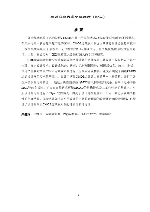
Fig.5.Measuredone-ports-parametervaluesforametal3squarespiralinductor,7.25turnsand12.4nH.
amorenonlinearpoweramplifier.Dependinguponthepeaktoaveragepowerratioofthesignalbeingamplified,theadja-centchannelpowerperformancealsodegradesastheconduc-tionangleisreducedbeyondacertainlimit.
III.INTEGRATEDINDUCTORMODELFORCADOPTIMIZATION
ShowninFig.5ismeasuredone-portmtriple-metalCMOSprocess.The29-segment(7.25turns)inductorformedonthemetal3layerwas15-minterturnspacing,anda100-GUPTAetal.:DESIGNANDOPTIMIZATIONOFCMOSRFPOWERAMPLIFIERS169Fig.6.Five-segment(1.25-turn)squarespiralinductorandalumpedequivalentcircuitmodel.
Fig.7.Lumpedelementcompactmodelrepresentingthefull-blownmodelofFig.6.
associatedwiththeinductor’sinnerandouterportsarenotidentical,asymmetricalcompactmodelisfoundtoapproxi-matetheinductorresponseadequatelyinthefrequencyrangeofinterest.Thevalueof
overadesiredrangeofinductances.FortheprocessandgeometryparameterslistedinTableI,thefollowingpolynomialswereobtainedforafloatinginductorintherangeof1nHto18nH:
(13)isinnH,170IEEEJOURNALOFSOLID-STATECIRCUITS,VOL.36,NO.2,FEBRUARY2001maintainasimplecompactmodel,werepresentbothinductiveandcapacitivesubstratelossesusinganeffectivelossresistance
andisanempiricalconstant.Thesubstrateresistanceisinitiallycal-culatedasthelateralspreadingresistance[12],andthenrefinedusingtheempiricalfactor
-parametervalues.Withproperchoiceof
loadtoadesiredimpedance.Asaresult,thedeterminationoftheoptimumloadimpedanceandthecorre-spondingmatchingnetworkdesigncanbecarriedoutastwodistinctdesignsteps.However,inthecaseofintegratedPAs,theoverallPAefficiencyisdeterminedbytwocomponents—theefficiencyatwhichthepowertransistor(s)operateandtheeffi-ciencyofthematchingnetworks.Notethattheefficienciesofthetransistorandthematchingnetworksarenotindependentofeachother.Thetransistorefficiency,foragiventechnology,de-pendsprimarilyupontheloadimpedancepresentedtoit,andhenceontheelementscomprisingthematchingnetwork.Ob-viously,thematchingnetworkelementsalsodeterminetheef-ficiencywithwhichthematchingnetworkdeliversRFpowerfromthetransistortotheload.Thus,thereisatrade-offbe-tweentheimpedancetransformationpropertiesoftheon-chipmatchingnetworksandtheoverallefficiencyofthepoweram-plifier.Itispossiblethatthebenefitinefficiencyobtainedbyoperatingthetransistormostefficientlyrequiresamatchingnet-workwhoselossoffsetsanyimprovementinoverallefficiencyofthePA.Usingthetraditionalapproachofdeterminingtheoptimumloadimpedanceusingload-pullandsubsequentlyde-signingthematchingnetworkisnotadequatefortherealiza-tionofhigh-efficiencyintegratedCMOSPAs.ThedesignoffullymonolithicPAsrequiressimultaneousdeterminationoftheloadimpedanceandthecorrespondingmatchingnetworkrealization,allowingthemaximumdegreeofoptimizationbyfullyexploringthetrade-offbetweenthematchingnetworklossanditsimpedancetransformation.Itislikelythatanintegratedmatchingnetworkmaynotperformanoptimumloadimpedancetransformation,butstillresultsinhigheroverallefficiencyduetolowerlossinit,comparedtoanoptimal(withrespecttoimpedancetransformation)integratedmatchingnetwork.Alter-natively,forintegratedPAs,anoptimumloadnetworkismoreappropriatelydefinedasonewhichresultsinbestoverallef-ficiency,andnotasanetworkwhichperformstheimpedancetransformationnecessarilydictatedbyconventionalload-pull.TheCADtooldescribedhereisdesignedtofindsuchanop-timummatchingnetworkforintegratedPAs.