材料模拟与计算 Asignment5
SJTU多尺度材料模拟与计算
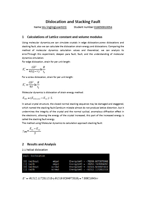
Dislocation and Stacking FaultName:Wu lingling(user023) Student number:0160509100541 Calculations of Lattice constant and volume modulusUsing molecular dynamics,we can simulate crystals in edge dislocation,screw dislocations and stacking fault, also we can calculate the dislocation strain energy and dislocations. Comparing the method of molecular dynamics calculation values and theoretical, we can analysis its error.Through this experiment, deepen para fault, fault, and the understanding of molecular dynamics simulation.For edge dislocation, strain for per unit length:20ln4(1)e eGb RE r πn =−For a screw dislocation, strain for per unit length:20ln4seGb R E r π= Molecular dynamics is dislocation of strain energy method:()/MD dislocated ref E E E L=−In actual crystal structure, the closed normal stacking sequence may be damaged and staggered,which named the stacking fault.Cambium mistake almost do not produce lattice distortion, but it undermines the integrity of the crystal and the normal cyclical, anomalous diffraction effect in the electronic, allowing the energy of the crystal increased, this part of the increased energy is called the stacking fault energy.The mathod using Molecular dynamics to calculation approach stacking fault:SFE =tot refE E Sγ−2 Results and Analysis2.1 helical dislocation-91512.1172811518-(-91519.9264975819)7.80921643sE ev =el =4.45685A A,so57.80921643 1.5326.0/7A 3A 95s s esE evE ev l ===A A When calculating Cu,0 3.639A a =A,0/2b a =,43.55G GPa =,we can get the result:20ln 0.6595(/A)4s eGb RE ev r π==A2.2 stacking fault-91512.1172811518-(-91519.9264975819)7.80921643sE ev =el =5.09537A AWhen calculating Cu,0 3.639A a =A,0/2b a =,43.55G GPa =, we can get theresult:20ln 0.6595(/A)4s eGb RE ev r π==A2.3 stacking faultE=244.0461825440018(mJ/m )For edge dislocation,when chocing x1=[6.81205 126.341 109.114] A and x2=[6.87178 126.333 141.831] A ,we can get 141.831109.11432.717A d −==A,so2102 1.30(10/)81s b J m m n πn −+•=−,2221=39.7347(/)81s b mJ m dm n γπn +••=− For helical dislocation,when chocing x1=[127.087 125.957 2.27685] A ,x2=[137.353 124.044 1.02476] A ,we can get 137.353127.08710.266A d −==A,so210230.585(10/)81s b J m m n πn −−•=−,222-31=56.9842(/)81s b mJ m d m n γπn ••=−.3 Summary form。
材料模拟与计算材料学

材料模拟与计算材料学材料模拟与计算在材料学中的应用材料模拟与计算是一种基于计算机技术的新型材料研究方法,它通过建立数学模型和计算模拟来揭示材料的结构、性能和特性,为材料设计和开发提供科学依据。
在当代材料科学领域,材料模拟与计算正发挥着越来越重要的作用,成为材料学研究的重要手段之一。
一、原理及方法材料模拟与计算主要运用分子动力学、密度泛函理论、有限元分析等方法,通过模拟材料在原子、分子尺度上的结构和行为,预测材料的性能及其在不同环境下的响应。
通过计算机软件的支持,可以高效地对材料进行建模、仿真和优化,加速材料研究的进程。
同时,材料模拟与计算还具有可重复性高、成本低、实验条件苛刻等优势,为材料科学的发展提供了新的可能性。
二、应用领域1.新材料设计材料模拟与计算可以帮助材料科学家快速筛选出潜在的新材料,并通过预测材料的性能,辅助设计出符合特定要求的材料结构。
比如在太阳能电池、电池材料、催化剂等领域,材料模拟与计算通过模拟材料的电子结构、光学性质等,为新材料的设计提供重要参考。
2.材料性能优化通过对材料的原子、分子结构进行模拟,可以深入研究材料的物理、化学性质,预测材料的性能优劣。
在材料表面改性、力学性能调控等方面,材料模拟与计算可以为材料性能的优化提供定量依据。
3.材料损伤和断裂行为分析材料模拟与计算可以模拟材料在外力作用下的应力分布、应变状态,预测材料的损伤和断裂行为。
通过模拟不同加载条件下材料的力学性能,可以指导材料的设计与寿命评估。
4.材料热力学性质研究材料模拟与计算可以模拟材料在不同温度、压力下的热力学性质,如热膨胀系数、热导率、比热容等。
可以帮助研究人员理解材料的相变规律,为热处理工艺和材料应用提供理论支持。
结语材料模拟与计算作为一种高效、可控的材料研究方法,在材料学领域发挥着越来越大的作用。
通过模拟与计算,可以深入理解材料的微观结构与性能,加速材料设计的过程,为材料科学的快速发展提供技术支持。
材料模拟与计算研究
材料模拟与计算研究材料科学是一门研究材料的性质、结构和性能的学科,而材料模拟与计算研究则是在材料科学领域中应用计算机模拟和计算方法来探究材料的行为和性质的一种方法。
随着计算机技术的不断发展和计算能力的提高,材料模拟与计算研究在材料科学中扮演着越来越重要的角色。
材料模拟与计算研究的核心是通过计算机模拟和计算方法来预测材料的性质和行为。
这种方法可以帮助科学家们在实验之前对材料进行预测和优化,从而节省时间和资源。
例如,在材料设计中,科学家们可以使用材料模拟和计算方法来预测不同材料的性能,从而选择最合适的材料用于特定的应用。
这种方法可以大大加速材料研发的过程,提高研究的效率。
在材料模拟与计算研究中,最常用的方法之一是分子动力学模拟。
分子动力学模拟是一种通过模拟材料中原子和分子的运动来研究材料性质的方法。
通过计算机模拟,科学家们可以观察材料中原子和分子的运动轨迹,并进一步研究材料的热力学性质、力学性质和电子性质等。
这种方法可以帮助科学家们理解材料的微观结构和宏观性质之间的关系,从而为材料设计和应用提供指导。
除了分子动力学模拟,材料模拟与计算研究还包括量子力学计算、连续介质力学模拟等方法。
量子力学计算是一种基于量子力学理论的计算方法,可以用来研究材料的电子结构和电子性质。
这种方法可以帮助科学家们预测材料的导电性、光学性质和磁性等特性。
连续介质力学模拟则是一种基于连续介质力学理论的计算方法,可以用来研究材料的力学性质和变形行为。
这种方法可以帮助科学家们预测材料的强度、硬度和韧性等性质。
材料模拟与计算研究在许多领域中都有广泛的应用。
例如,在材料设计和合成中,科学家们可以使用材料模拟和计算方法来预测不同材料的结构和性能,从而指导实验的设计和合成过程。
在材料表征和测试中,科学家们可以使用材料模拟和计算方法来解释实验结果,从而深入理解材料的行为和性质。
在材料应用和工程中,科学家们可以使用材料模拟和计算方法来优化材料的性能和结构,从而提高材料的应用效果和工程性能。
材料成型计算机模拟考试复习资料
材料成型计算机模拟考试复习资料一、判断题(共5分)1. Anycasting 是一款基于有限元原理的模拟铸造成型过程的数值分析软件。
( × )2. 相对于有限元法,有限差分法的弱项在于应力分析。
( √ )3. Sysweld 、Ansys 、Procasting 、Deform 都可以模拟焊接过程的专业有限元分析软。
( × )4. 进行材料成型过程数值模拟时,对材料的热物理性能参数要求不严格。
( × )5. 一维空间Fourier 定律表示成下式:q=x-t λ。
( √ ) 二、填空题(共25分)1. 材料科学是以材料的组成、结构、性能和加工等为研究对象的一门科学。
2. 材料成形即采用铸造、锻造、焊接等方法将金属原材料加工成所需形状、尺寸,并达到一定的组织性能要求。
3. 材料按照组成与结构可以分为金属材料、无机非金属材料、有机高分子材料和复合材料等。
4. 数学建模的过程包括:建模准备、建模假设、构造模型、模型求解、模型分析、模型检验、模型应用。
5. 材料、能源和信息称为当代文明的三大支柱。
6. 材料按照性能和作用可以分为结构材料和功能材料。
7. 材料成型方法涉及到的物理、化学和力学现象。
8. 有限元分析的后处理程序的功能分为对计算结果的加工处理和计算结果的(图形)表示。
9. 金属型模具温度场的分析步骤分为前处理、求解和后处理。
10. 用于表示计算结果的图形表示形式有结构变形图、等值线图、主应力迹线图、等色图。
11. 当x 方向的温度分布呈线性时,温度梯度表达式:1212x T x T T x --=??。
12. 材料加工过程数值仿真的初始条件包括:温度初始条件、压力初始条件、速度初始条件和组织初始条件。
13. 在有限元法诞生前,求解弹性力学定解问题的基本方法有按应力求解、按位移求解和混合求解。
14. 材料成形过程的基本规律可以用一组微分方程来描述,例如流场方程、热传导方程、平衡方程和运动方程等,这些方程在所讨论的问题中常常被称为场方程或控制方程。
材料的计算机模拟方法优秀课件

Hˆ E
Hˆ TˆVˆ
Tˆ2
2mi
1 2 2 2 mi (x2 i y2 i z2 i )
动能是所有粒子的动能加和
Vˆ 1
qjqk
4 j kj rk rj
势能代表粒子之间的库仑相互作用 (即:核与核之间、电子与电子之间 的排斥以及电子与核之间的吸引)
对电子而言,q=-e,对核而言,原子序数为Z:q=+Ze。
如6-21G 表示内层原子轨道用六个高斯基函数来描述,内层价壳则用两个高 斯基函数表示,外层价壳用一个高斯函数表示。
类似地还有:3-21G, 4-31G, 以及 6-311G 等等。
➢ 带极化函数的基组,在基组中加入极化函数后可以允许原子核外电荷的不 均匀位移,因此它可以改进对化学键的描述。极化函数可以描述那些和孤 立原子相比更高的角动量量子数的轨道(如p-型函数用于H和He,d-型函 数用于Z>2的原子),并将之加入到价电子壳层中。例如,6-31G(d) 基组 的构建是将6个d-型简单高斯函数加入到6-31G 中来描述每个非氢原子; 同样地,6-31G(d,p) 是6-31G(d) 对重原子, 但加入了一组p-型高斯函数到 氢原子或氦原子。 将p-轨道加入到氢原子中对那些含有以氢原子为桥原子 的体系而言特别有用。
通过对这些性质的预测,在含能材料中有许多实用
价值,如:可以研究合成路径、反应产物、爆轰产 物状态方程、爆轰引发的机理等等。
关于材料计算与模拟的内容

关于材料计算与模拟的内容
材料计算与模拟是近年来发展迅猛的新兴学科,它涉及数学、计算机科学、物理学和化学等多个学科,其中最重要的便是物理。
材料计算与模拟技术在许多科学领域有重要的应用,尤其是在材料科学和工程中的应用最为广泛。
材料计算与模拟旨在利用计算机来模拟材料的表现,以深入理解其行为机理,从而获得预期的性能和功能。
材料的表现受限于它的内部特性,它的模型可以被用来模拟材料的体系结构、物理化学机理、形状和外观。
材料计算与模拟包括多种技术,其中包括量子力学、分子动力学、原子力学、元胞自动机、速度模拟、拉普拉斯和有限元等技术。
这些技术可以用来模拟物理、化学和结构属性,以及材料的性能特性,以及材料的可靠性、机械行为等。
这些技术也可以用来预测材料的结构、属性、性能、可靠性和行为,设计高性能、超强可靠性的材料,并对材料的行为做出准确的预测。
材料计算与模拟技术不仅可以用来分析材料,还可以用来设计新型材料,比如能源、环境和生物技术领域等。
它可以用来解决许多复杂的科学问题,总结和分析材料及其产品之间的关系,帮助开发出更先进的新型材料。
因此,材料计算与模拟技术在材料科学和工程中非常重要。
它不仅可以用来模拟材料的性能特性,还可以用来设计、开发具有性能优越的新型材料。
材料计算与模拟是一门极具前景的学科,其发展不仅
有助于推进材料科学,还有助于促进相关应用领域的发展。
材料科学中的计算模拟
材料科学中的计算模拟材料科学是研究材料的性质、结构、制备、加工行为和应用的一门学科。
在材料科学领域,理论模型和计算模拟已经成为解决问题和设计新材料的有力工具之一。
计算模拟能够通过建立材料结构的模型,进一步研究和预测材料的性质和行为。
在材料选择和设计方面,计算模拟为材料工程师提供了重要的决策支持。
在本文中,我们将介绍材料科学中的计算模拟方法和应用。
1. 分子动力学模拟分子动力学模拟是一种基于数值方法的计算模拟技术。
它通过求解分子在作用力场中的运动轨迹和相互作用力,模拟和预测材料宏观和微观物理性质的变化。
基于分子动力学模拟技术,已经研究了诸如金属、合金、半导体、陶瓷、软物质等广泛的材料。
分子动力学技术可以为研究材料的性质和行为提供微观尺度的详细信息。
2. 真实时间密度泛函理论模拟密度泛函理论是研究电子结构和分子间相互作用的理论方法。
真实时间密度泛函理论模拟(RTDFT)是一种基于密度泛函理论的计算模拟方法,用于描述电子结构的运动和时间演化,模拟材料的电子结构和光谱性质。
RTDFT技术是一种计算量较大的方法,但是它提供了高精度的材料性质预测,可以用于研究光电器件和光电材料的性质和行为。
3. 第一性原理计算第一性原理计算是材料计算模拟中最常用的方法之一。
这种方法是基于量子力学的,能够计算材料中每个原子的电子结构、能带结构、介电常数、晶格常数、热力学性质等各种物理量。
第一性原理计算技术可以为实验不可测的材料提供预测性的信息。
目前,在能源、光电技术、生物医药等领域都有第一性原理计算的应用。
4. 有限元方法模拟有限元方法模拟是在工程学科中普遍使用的一种计算模拟技术。
它用于分析物体在复杂载荷和能力下的应变、变形、应力等各种物理量。
有限元方法在材料科学领域可以用于研究变形行为、断裂行为、力学性质和热力学性质等方面。
有限元方法是一种将局部信息扩展到全局的方法,它可以为工程设计和优化提供有力支持。
5. 神经网络模拟神经网络模拟是一种类似生物神经系统的计算模拟技术。
材料计算与模拟
当argv是数值或数值表达式时,flagv取:
‘d’; ‘e’; ‘f’; ‘r’。
argv是字符时,flagv可取一下限定选项:
‘positive’ 限定argv为正、实符号变量;
‘real’
限定argv为实符号变量;
‘unreal’
argv为非实符号变量。
1.7.1 因式分解(Factor)
例:分解一个代数式f(x)=x3+3x2+3x+1
着色模式:
shading flat shading interp shading faceted
三维图形:
举例:plot3() clear clc z=0:0.1:4*pi; x=cos(z); y=sin(z); plot3(x,y,z)
三维图形:
举例:surf() t=0:pi/10:2*pi; [X,Y,Z]=cylinder(2+sin(t)); surf(X,Y,Z) axis square
f2(x,y)
%调用内联函数
1.4 Matlab 数组
1.4.1 一维数组
创建: x = [1, 2, 3] 访问: x(3)
1.4.2 两维数组
创建: x = [1, 2, 3; 4, 5, 6] 访问: x(2,2)
1.4.3 数组操作
1数组的创建:ones 0 数组的创建:zeros 插入行或列 重新排列 删除某行或列 用单个下标操作一个矩阵
整理成x的多项式:
专用软件:
Cerius 2; Materials Studio Gaussian03
材料计算
第一章 Matlab 基本操作及应用 第二章 材料计算示例
常规数值计算 计算机模拟基础 (Monte Carlo法)
- 1、下载文档前请自行甄别文档内容的完整性,平台不提供额外的编辑、内容补充、找答案等附加服务。
- 2、"仅部分预览"的文档,不可在线预览部分如存在完整性等问题,可反馈申请退款(可完整预览的文档不适用该条件!)。
- 3、如文档侵犯您的权益,请联系客服反馈,我们会尽快为您处理(人工客服工作时间:9:00-18:30)。
完成下面两个练习,提交截图1.QM/MM calculation of the SW1 defect formation energy for a carbon Purpose: Introduces how to use the QMERA module in Materials Studio. Special attention is paid to preparing the system and which type of embedding scheme to use.Modules: Materials Visualizer, QMERATime:Prerequisites: NoneThe Stone-Wales (SW) defect is a common defect on carbon nanotubes that is thought to have important implications for their mechanical properties (see Andzelm et al., 2006). The 90° rotation of two carbon atoms around the midpoint of the C-C bond transforms four hexagons into two pentagons and two heptagons. This substructure is known as Stone-Wales defect. In this tutorial you will calculate the formation energy of a nonchiral SW defect (SW1).The following steps will be covered here:Getting startedQM region definitionQMERA calculationAnalysis of resultsNote: In order to ensure that you can follow this tutorial exactly as intended, you should use the1. Getting startedBegin by starting Materials Studio and creating a new project.Open the New Project dialog and enter Stone-Wales as the project name, click the OK button.The new project is created with Stone-Wales listed in the Project Explorer.2. Structure preparationThe first thing you need to do is prepare the structure of the single-walled nanotube (SWNT).Select Build | Build Nanostructure | Single-Wall Nanotube from the menu bar. Change the N and M indices to 8 and 0 respectively.This corresponds to a nanotube of 6.26 Å diameter.Uncheck the Periodic nanotube box and change the number of Repeat units to 7, this gives a nanotube length of 29.82 Å. Select Both ends from the Hydrogen termination dropdown list. Click the Build button and close the dialog.Now you have to create the defect in the middle of the nanotube.Right-click in the 3D Viewer and select Display Style from the shortcut menu to open the Display Style dialog. Click the Stick radio button and close the dialog.Press the LEFT arrow key twice to rotate the nanotube so that you can see its full length horizontally. The Z axis should be pointing to the left and the Y axis should be pointing up, on the axis orientation display, see Figure 1.Select two carbon atoms which are near the center of the nanotube wall and which are connected by a horizontal bond and then select the remainder of benzene rings at each end of the bond.Figure 1. SWNT with two central carbon atoms and their pendant benzene rings selected.Click on the arrow for the 3D Viewer Recenter from the toolbar and select View Onto fromthe dropdown list. Click anywhere in the 3D Viewer to deselect everything and reselect the central two carbon atoms.Figure 2. SWNT viewed from above, with two central carbon atoms selected.Select the Movement tools from the toolbar, change the Angle to 90.0 and click the Move Around Z button. Close the dialog.This creates the defect by rotating the two carbon atoms 90° around the screen Z axis.To view the appropriate connectivity select Build | Bonds from the menu bar to open the Bond Calculation dialog. Uncheck Calculate bond type, set the Convert representation to option to Resonant. Click the Calculate button and close the dialog.Rename the SWNT.xsd document to SW1.xsd.Figure 3. SW1 defect (highlighted here in blue) on an SWNT.3. QM region definitionThe next step is to define the QM region that you want to use in the simulation. It is necessary to include full rings in the calculation to avoid possible clashes between hydrogen link atoms, and to leave enough space between the defect and the boundary QM-MM atoms. In this case you will include the defect plus a crown of full rings around it in the QM region (see Figure 4).With the two carbon atoms central to the defect still selected, choose Edit | Atom Selection from the menu bar to open the Selection dialog. Select Connected from the Select by Property dropdown list and choose the Add to the existing selection radio button. Click the Select button four times and close the dialog. Hold down the SHIFT key and select the four carbons needed to complete the crown of six-membered rings.Select | Calculation from the modules toolbar to open the QMERA Calculation dialog. Click the Add button to add the selected atoms to the QuantumAtoms set.Click anywhere in the 3D Viewer, the atoms in the set will be highlighted in purple.Figure 4. SW1 defect with the QuantumAtoms set defined.If you want to visualize the hydrogen link atoms to be sure that there are no problems related to their position, you can use the View button on the QMERA Calculation dialog.On the Setup tab of the QMERA Calculation dialog click the View button. A new window will open, double-click on the LinkAtoms label. Check that the position of the hydrogen link atoms makes sense and close the window. Click the No button on the dialog asking whether to save the document.4. QMERA calculationYou are now ready to run the QMERA calculation. In this case the polarization effects are negligible and the charges of all atoms will be left as zero, which is compatible with the Dreiding forcefield. It is also sufficient to choose a mechanical embedding approach for the QM/MM calculation.There are two different models available for mechanical embedding: QM-Pot and additive. You will use the QM-Pot model which uses a subtractive expression to calculate the total energy. Forcefield parameters are therefore required for all atoms of the system.On the Setup tab of the QMERA Calculation dialog select Geometry Optimization as the Task and ensure that the Quality of the calculation is set to Medium.In order to complete the tutorial more quickly, you could use the Coarse quality setting.Click the More... button associated with the task, to open the QMERA Geometry Optimization dialog. Select HDLC as the Method and close the dialog.The HDLC minimizer combines the use of highly decoupled delocalized internal coordinates with the linear scaling BFGS update of the Hessian (L-BFGS) method. This usually achieves faster convergence than normal BFGS or conjugate gradient methods for covalent systems of this size.Click the More... button for the QM server to open the QMERA DMol3 Parameters dialog. Select GGA and PBE for the functional and close the dialog.Click the More... button for the MM server to open the QMERA GULP Parameters dialog. Ensure that Dreiding is selected as the Forcefield and Use current is selected for Charges, close the dialog. Select the Options tab of the QMERA Calculation dialog, ensure that Mechanical is selected as the Embedding scheme and Model is set to QM-Pot. Click the Run button.GGA functionals provide a good description of the electronic subsystem and the PBE exchangecorrelation functional has previously been identified as efficient for QM/MM calculations on nanotubes, see Andzelm et al., 2006 for similar calculations.Depending on your hardware, this calculation may take several hours to complete. If you wish to examine and analyze the results directly the output files are provided in theExamples/Projects/QMERA/Stone-Wales Files/Documents/ directory in the SW1 QMERA GeomOpt and SWNT QMERA GeomOpt folders.5. Analysis of resultsThe results of the calculation will be returned in a new folder called SW1 QMERA GeomOpt.Open the SW1.xsd file in the SW1 QMERA GeomOpt folder to see the optimized geometry.The final energy for this structure can be found in the SW1.csout file, the QM/MM Energy heading reports the corresponding energy in a.u., which is Hartree in this case.Double-click on SW1.csout to open the energy file, press the CTRL + F keys and enter Energy (subtractive) into the Find dialog.The end of the file is displayed. Scroll up a little and examine the QM/MM Energy.To examine the relationship between the energy and the structure you can compare the energy chart with the trajectory. You will need to analyze the results to obtain the trajectory and chart documents, even if you already have some charts with intermediate updates.Select Modules | QMERA | Analysis from the menu bar to open the QMERA Analysis dialog. Select Energy evolution and click the View button. Close the dialog.The energy evolution either creates or opens two chart documents, called SW1 Energies.xcd and SW1 Convergence.xcd.Make SW1.xtd the active document and, on the animation toolbar, click on the Play button.As the animation proceeds the seven-membered rings widen.Stop the animation and open SW1 Energies.xcd.Click on a point on the graph near the beginning of the optimization.The 3D Viewer displays the structure at the corresponding step in the calculation. In this way you can examine the structure at specific energies during the calculation.To obtain the formation energy for the SW1 defect you need to perform a QMERA calculation with the same settings for the defect free nanotube. To do this you should use a QM region of four fused C6 rings and a surrounding crown. The resultant QM region will be similar to the one shown in Figure 4, except that the central C-C bond of the QM region in Figure 4 will be horizontal rather than vertical. The output files for this calculation are provided in the Examples/Projects/QMERA/Stone-Wales Files/Documents/SWNT QMERA GeomOpt/ folder.Once you have both calculations you can calculate the formation energy of the SW1 defect as the difference in QM/MM Energy, converting from atomic units to eV according to: 1 a.u. (Hartree) =27.2113845 eV.You should obtain a value of around 2.1 eV.This is the end of this tutorial.ReferenceAndzelm, J., Govind, N., Maiti, A., Chem. Phys. Lett., 2006, (421), 58-62.2.QM/MM geometry optimization of a Ru(H)2(diphosphine)(diamine) Purpose: Introduces how to use the QMERA module in Materials Studio with special attention paidto which type of embedding scheme to use.Modules: Materials Visualizer, QMERATime:Prerequisites: NoneThe preparation of enantiomerically pure alcohols is of high importance in drug design. A breakthrough in this field was the discovery, by Noyori and co-workers, of highly efficient ruthenium catalysts for the enantioselective hydrogenation of ketones (R. Noyori, Angew. Chem., Int. Ed., 2002, 41, 2008). Among the best catalysts for carbonyl hydrogenation are octahedral complexes where Ru(II) is coordinated by a chiral diphosphine and a chiral diamine.Figure 1. Conversion of a ketone to a chiral secondary alcohol.In this tutorial you will use the QMERA module in Materials Studio to optimize the structure of a Ru(H)2 (diphosphine)(diamine) complex. You will use DMol3 to describe the QM region and the Dreiding forcefield to describe the MM region. The following steps will be covered here:Getting startedStructure and QM/MM setupQMERA calculationNote: In order to ensure that you can follow this tutorial exactly as intended, you should use the1. Getting startedBegin by starting Materials Studio and creating a new project.Open the New Project dialog and enter Ru_complex as the project name, click the OK button.The new project is created with Ru_complex listed in the Project Explorer.2. Structure and QM/MM setupThe structure you will use is shown below:Figure 2. Ru(II) complex used as an asymmetric hydrogenation catalyst for ketones.Select File | Import... from the menu bar and browse to Examples\Projects\QMERA\Ru_complex Files\Documents\Ru_start.xsd. Click the Open button.Once you have the structure of the complex you can prepare the QMERA calculation. For this system you will include the polarization of the QM region due to the MM region. To this end, you will include the MM point charges in the SCF part of the QM calculation. This type of approach is called electrostatic embedding and it does not require forcefield parameters for the QM region, for either atom types or charges, because an additive expression is used to calculate the total energy of the system.You need to define the QM region first. The atoms to include in the QM region are shown in Figure 3. The QM region includes the Ru center, the two hydrides (H), the two P atoms and the H2NCHCHNH2 diamine backbone.Figure 3. Ru(II) complex with the QM region indicated using stick representation.Use the selection tool to select the QM region indicated above. Select the QMERA modulefrom the Modules toolbar and choose Calculation to open the QMERA Calculation dialog. Click the Add button to add the selected atoms to the QuantumAtoms set.Click anywhere in the 3D Viewer, the atoms in the set will be highlighted in purple.If you want to visualize the hydrogen link atoms to be sure that there are no problems related to their position, you can use the View button in the QMERA Calculation dialog.On the Setup tab of the QMERA Calculation dialog click the View button. A new window will open with the LinkAtoms selected. Check that the position of the hydrogen link atoms makes sense and close the window. Click the No button on the dialog which asks if you want to save this document. You need to setup and modify the ligand charges. In electronic embedding methods, the basic requirement for the choice of charges is that net charge of the MM atoms must be integer. In this case this is achieved by using the QEq method to calculate separately the charges of each ligand bound to the QM region, under the constraint that the net charge must be zero.Select Modify | Charges from the menu bar to open the Charges dialog. On the Calculate tab choose QEq as the Method. Select one of the MM ligand residues (for example a phenyl ring) and click the Calculate button. The ligand charges have been determined now. Repeat this procedure for all the other MM ligands.Close the Charges dialog.Note that the atoms in the QM region do not need to have charges assigned.The prepared structure can also be imported from Examples\Projects\QMERA\Ru_complex Files\Documents\Ru_complex.xsd.You can now run the QMERA calculation.3. QMERA calculationOn the Setup tab of the QMERA Calculation dialog, select Geometry Optimization as the Task and Medium for the Quality of the calculation. Click the More... button for the Task to open the QMERA Geometry Optimization dialog.Select HDLC as the Method and close the dialog.Click the More... button for the QM server to open QMERA DMol3 Parameters dialog. Select GGA and PBE for the Functional and close the dialog.This Ru(II) complex has a zero net QM charge, the two hydride ligands act as electron donors (2 × -1) to compensate for the metal's 2+ charge and no other QM atoms contribute charges (all other ligands coordinate the Ru center through dative bonding). So the DMol3 charge can remain at a value of zero for this system.For the MM server click the More... button to open the QMERA GULP Parameters dialog. Select Dreiding as the Forcefield and Use current for the Charges, close the dialog.On the QMERA Calculation dialog, click on the Options tab and select Electronic as the Embedding scheme and Disperse boundary charge as the Model. Click the Run button.Depending on your hardware, this calculation may take several hours to complete. If you wish to examine and analyze the results directly the output files are provided in theExamples\Projects\QMERA\Ru_complex Files\Documents\ directory in the Ru_complex QMERA GeomOpt folder.After performing the calculation for the Ru(II) complex you can proceed to include the substrate (ketone) in the calculation. The ketone will belong to the QM region and as a consequence you do not need charges or atom types for that structure. You can draw the ketone in the same document as the Ru(II) complex and add it to the QM region using the Add button on the QMERA Calculation dialog.The prepared structure for the complex and substrate can be found atExamples\Projects\QMERA\Ru_complex Files\Documents\Ru_complex+ketone_2.xsd. If you wish to examine and analyze the results of the QM/MM calculation on the ketone system directly, the output files from the QMERA run can be found in the Examples\Projects\QMERA\Ru_ complex Files\Documents\Ru_complex+ketone_2 QMERA GeomOpt folder.。
