NTC说明书
热敏电阻NTC数据手册说明书

传感器SENSORSSENSOR MANUALTEMPERATUREMEASUREMENTCONTROLSHANGHAI BENMU INDUSTRY CO., LTD.上海本牧实业有限公司QUICK LINKSCONNECTINGSENSOR TECH电阻值耗散常数ResistanceThermal dissipation constantB值热时间常数B constantThermal time constant热敏电阻的电阻值R和绝对温度T之间,有以下近似关系。
Between resistance R and absolute temperature T, there is the following approximate relationship.11T1T2根据公式、可以求证任意温度T时的热敏电阻R。
Thermistor resistance R at any temperature T can be calculated from equation (1)R1: Resistance (Ω) at absolute temperature T1 (K)绝对温度T1 (K) 时的电阻值R2: Resistance (Ω) at absolute temperature T2 (K)绝对温度T2 (K) 时的电阻值A thermistor is "a thermally sensitive resistor"that is a semiconductor whose resistance varies significantly with temperature.In general,there are two types thermal senstive resistor.One is PTC (Postive Temperature Coefficient);the resistance increases as temperature increases.The other is NTC (Negative Temperature Coefficient);the resistance decreases as temperature increases.The following description is applicable only to NTC thermistors.热敏电阻是应用于信息系统与控制系统的敏感元件,主要用于对温度的测量、控制、保护及用作加热器。
NTC温敏阻器应用说明书

Understanding the current limiting capabilities of power NTC thermistorsOverview - What are inrush current limiters or powerthermistors?Power NTC thermistors are made of a metal-oxide ceramic materialin the form of ceramic discs that help provide protection againstdamaging inrush currents upon equipment startup and/or switchingon. As such, they are commonly referred to as Inrush CurrentThis application note examines the general uses of power NTCthermistors, the relevant parameters of power NTC thermistordatasheets, and some best practices for the use of thesethermistors. It finishes by detailing some illustrative use casesand applications.How power NTC thermistors are usedT ypically, circuits will offer a low impedance when switched on.The initial low impedance could be due to the capacitors rapidlydischarging, motors not turning immediately, or heaters beingcold at startup. This window of low impedance could yield an“inrush” current. Power NTC thermistors, or ICLs, will exhibit a highresistance at room temperature (25 ºC). This effectively absorbsthe power of the peak inrush currents at startup. However, whenheated, the resistance of the ICL drops sharply. This means thatthe ICL will heat up as a result of the current load and can drop itsresistance up to between one fifth to one half of its full value (seeFigure 1). Therefore, the power consumption of the ICL is morenegligible in continuous operation. This is the major advantageof ICLs over standard fixed resistors; using these devices allowsdesigners to establish a higher system efficiency.Technical Data ELX1247Effective July 2022NTC thermistors application note/electronicsFigure 1: Sample R-T of a power NTC thermistor.Power NTC thermistor datasheet parameters explained Maximum continuous current ratingAfter the power thermistor heats up upon the initial surge of current, its resistance will drop and it will pass the steady-state current of the application circuit. This is where the maximum continuous current rating is pertinent: the steady-state current of the application should not exceed the continuous current rating of the ICL. For a switch-mode power supply (SMPS), this steady-state current can be calculated with the following Equation 1. When sizing the power thermistor, it is important to take into account the voltage line fluctuations and different operating states of the application circuit.Equation 1The ICL ’s steady-state current rating relies upon the ambienttemperature (T A ) that the device will operate in. As with any thermally dependent device, there is a given derating where the maximum current rating will decrease at temperatures above a certain point. These derating curves are modeled around PCBs with heat sinking and passive cooling/no airflow. Generally speaking, the maximum current rating will begin to decline at ambient temperatures outside of 0 ºC and 25 ºC.Zero power resistanceDatasheets will typically list the resistance value specified at 25 ºC, or the zero power resistance. This is the initial resistance the power thermistor provides to prevent the inrush current from damagingsensitive downstream components. This resistance is implemented at different disc sizes with different values for continuous load and pulse strength. Generally, the larger the disc size, the higher the steady-state current it will be rated for.The minimum zero power resistance is selected by identifying the voltage of the application and dividing the maximum desired peak surge current of the equipment. (see Equation 2). Themaximum peak voltage (V peak ) can be calculated from the maximum line voltage (see Equation 3). For example, a 110 VAC power supply with line voltage fluctuations that can inflate that value by 10% would yield a V max voltage of 121 V . Then, maximum peak voltage (V peak ) would be 171 V .Equation 2Equation 3There are, however, cases where users may want more peak current reduction. In order to do this, users can select a component with an increased zero power resistance.Load capacitance of the device to be protectedAs stated earlier, the current at turn-on is much higher than the current at steady-state for applications that require ICLs. These high inrush currents are due to the higher energy required to power the application circuit at turn on. This energy should be known to properly select the ICL. Through industry standard testing, Eaton has defined the maximum capacitance in a 240 Vac application the ICLs can help limit and protect; however, this can be converted into a capacitance for a given voltage with Equation 4.Equation 4General power NTC thermistor operational considerationsWhile these devices offer a desirable alternative to fixed resistors, there are some potential design constraints to be aware of when applying a power NTC thermistor:•Consider the time it takes for the resistance to drop - The amount of time it takes for the resistance to fall relies on the magnitude of the in-rush current.•They self-heat - Power thermistors are resistance-based devices and can run at a high temperature during normal operation. As a result, its thermal dissipation and those ofnearby heat-sensitive components may need to be considered (see Figure 1).•Sizing is critical - An excessive load current can overheat the power NTC thermistor and potentially damage it. As a result, the ICL must be sized properly according to the application.•It takes time to return to its nominal resistance value - Once the initial surge of current has finished, the ICL will take time (several tens of seconds) to return to its normal resistance value. In many cases, this means a window of time before turning on equipment once more. But often, the factors leading to inrush conditions (discharged capacitors, forinstance) have not been reintroduced.Technical Data ELX1247Effective July 2022 NTC thermistors application noteEatonElectronics Division1000 Eaton BoulevardCleveland, OH 44122United States/electronics© 2022 EatonAll Rights ReservedPrinted in USAPublication No. ELX1247 BU-ELX22109x July 2022Eaton is a registered trademark.All other trademarks are propertyof their respective owners.Follow us on social media to get thelatest product and support information.• Ambient temperature changes need to be accounted for - These devices operate on a temperature rise and are therefore difficult to apply over a wide ambient temperature range. The thermal derating curve is provided in the respective datasheets.• They do not replace fuses - Fuses are still required to add the necessary short circuit protection. Instead, these devices should be used in conjunction as the combination helps reduce the nuisance of fuses opening.Power NTC thermistor applications and use casesInrush current limiting in switching power supplies Current surges in switched-mode power supplies (SMPS) stem from the large filter capacitors that are used to smooth out any voltage ripple from the 60 Hz rectified signal before going into the DC-DC converter. The initial charging of the input filter, filter capacitors, and output filter of the converter/load will result in a surge current. The NTC prevents the surge current from damaging sensitive components and allows the capacitors to reach their steady-state charge voltage. NTCs can be used in an SMPS before or after the rectifier, on the AC or DC side of the circuit(see Figure 2).Figure 2: Sample application circuit for power NTC thermistors used in an SMPS.This very same methodology can be applied to AC-DC and DC-DC converters to limit inrush current applied to the input and output capacitors at turn-on (see Figures 3 and 4).Figure 3: Sample application circuit with power NTC thermistor for aAC-DC converter.Figure 4: Sample application circuit with power NTC thermistor for aDC-DC converter.Final notesPower NTC thermistors can offer an elegant solution alternative to fixed resistors in power supplies and converters that experience an initial surge current due to their input, filter, and output capacitors. This is due to the fact that these thermally sensitive resistors will drop in resistance after they have successfully absorbed the initial impact of the surge current, thereby minimizing their amount of power consumption. Fixed resistors, on the other hand, will dissipate a set amount of power even while the application is oper-ating in steady-state. While ICLs do not replace fuses, they can beused in tandem to minimize the nuisance of fuses opening.。
维莎BCcomponents NTCLE引线式NTC热敏电阻器使用说明书

Important Information on the Use ofNTCLE Leaded NTC ThermistorsMOUNTING INSTRUCTIONS1. SOLDERINGLeaded thermistors comply with the solderability requirements outlined in IEC 60068-2-20. To prevent damage when soldering leaded NTC thermistors, care must be taken to prevent excessive heat from being conducted through the leadwires or directly to the thermistor body. The maximum process temperatures, the maximum time of exposure, and the minimum distances that need to be respected also depend on the material used for the leadwires. For dip, wave, and iron soldering of RoHS-compliant NTC thermistors, the combined solder conditions listed below should be followed:The use of resin-type flux or non-activated flux is recommended. Failure to follow the above soldering conditions may result in thermal-electrical damage to material and permanent resistance changes. NTCLE thermistors are not designed for reflow soldering processes. If a heat shrink tube is applied to an NTCLE thermistor, the heating temperature of the shrink tube must not exceed the mentioned reflow soldering temperatures and times. Use of the coating outlets as product stops should be avoided, as lacquer may enter the PCB holes and prevent solder flow and the minimum distance required between the solder joint and thermistor body cannot be reached. Excessive heating can cause the internal solder junction to melt.2. COLD JOINING AND WIRE BENDINGCold joining techniques such as crimp splicing can be applied to NTCLE thermistors for connector applications and making cable wire extensions. When crimp splicing, care should be taken to avoid causing intermittent contacts. The robustness of the termination leads meet the requirements of IEC 60068-2-21. During bending or separating of the leads, there should be no mechanical stress at the outlet of the coated sensor, and the leads may not be bent closer than 4 mm from the outlet of the coated body. The bending radius should be at least 3 x the wire diameter or a minimum of 5 x the insulated wire diameter. The part should not be exposed to mechanical stresses, including tensile, torsion or vibration forces, during normal operation in the application. For shrink tube fixation of the thermistor body and wires, see the “Soldering” section (1) of this document.3. STORAGE - SHELF LIFENTCLE thermistors need to be stored in their original packing containers. The storage location and package containers need to be maintained within following limits:Thermistors must not be stored in corrosive or deoxidizing atmospheres (Cl 2, H 2S, NH 3, NO x , SO x , etc.). Avoid storage in heat or direct (UV) sunlight. The presence of ozone or ionizing radiation must be avoided all times. H umidity, temperature, and container materials are critical factors that can influence the solderability of the parts. Touching the exposed metal leadwires may change their soldering properties.Shelf life: properly packaged and stored NTCLE thermistors have a minimum shelf life of 24 months after their manufacturing date (DC). Thermo-electrical functionality will not be influenced after longer storage time under the conditions described above. The solderability of exposed leads should be checked before using parts that have been stored for more than 24 months storage after their manufacturing date.LEADED NTC THERMISTORS: NTCLEWITH Cu WIRESØ < 0.65 mmWITH Ni OR STEEL WIRES Ø < 0.55 mm Wave or Dip SolderingMaximum bath or wave temperature260 °C 260 °C Maximum soldering time3 s 5 s Minimum distance from thermistor body6 mm 3 mm Solder Iron (Manual or Robot)Maximum solder tip temperature340 °C 340 °C Maximum soldering iron wattage30 W 30 W Maximum soldering time2 s3 s Minimum distance from thermistor body6 mm 3 mm PiP / PiH Reflow SolderingNot recommended Not recommended Maximum thermistor body temperature T pToper. Maximum +15 °C Toper. Maximum +25 °C Maximum exposure time to T p max.30 s 30 sStorage temperature:10 °C to 40 °CRelative humidity (without condensation):10 % to 70 %4. HANDLINGNTCLE thermistors must not be dropped. When handling the devices, chip-offs or any other damage must be avoided. Do not touch components with bare hands; gloves are recommended to prevent contamination of thermistor surface during handling. Rough handling of NTCLE thermistors may result in coating adhesion failures or coating cracks. For non-insulated NTCLE thermistors, please refer to the “Visual” paragraph of “Inspection Measuring” section (7) of this document.5. SEALING AND POTTINGNTCLE thermistors may only be sealed, potted, or overmolded in suitable resins if it is clearly mentioned and allowed in their respective datasheets. The following series cannot be potted: the NTCLE100 standard precision, and NTCLE101 and NTCLE203 accuracy lines. Sealing or potting can affect the reliability of the component. The potting material must be compatible with the use of electronic components, electrically non-conductive, and chemically stable across the whole operating temperature range. Potting or overmolding in polyamide-based resins is not recommended. When sealing, potting, or overmolding is permitted according to the datasheet, there must be no mechanical stress exerted on the component due to thermal expansion or compression during the production process (curing / overmolding) or in the final application. There must be no residual forces or stress on the device during normal operation. The upper category operating temperature of the thermistor must not be exceeded. Ensure that the materials used are chemically neutral and stable at the maximum operating temperature. If using a ceramic adhesive / potting or filling material, avoid phosphate-based binders. As thermistors are temperature-sensitive components, molding and sealing will affect the thermal surrounding and will influence the response time, power dissipation, and thermal gradient. Extensive testing is encouraged in order to determine whether overmolding or potting influences the functionality and / or reliability of the component.6. CLEANINGCleaning processes can affect the reliability of the component. If cleaning is necessary, mild cleaning agents are recommended. Cleaning agents based on water are not allowed. Washing processes may damage the product due to the possible static or cyclic mechanical loads (e.g. ultrasonic cleaning). They may cause cracks, which might lead to reduced reliability and / or lifetime. Intensive spraying may lead to coating damage.7. INSPECTION MEASURINGResistance Versus TemperatureNTC thermistors exhibit a large resistance change depending on the changing surrounding temperature. The change of resistance can be as high as -8 % per degree Celsius. When measuring or inspecting resistance values of precision NTC thermistors, it is advisable to immerse the thermistor body and its connecting leads in a good thermal conductive homogeneous medium. Such a medium is preferably silicone oil or PFPEs non-reactive, per-fluorinated liquid polymers. Water is not recommended, because of its electrical conductivity. In any case, the measured parts should be cleaned and dried before further use or be discarded. The liquid medium should be measured with a calibrated thermometer and referenced close to the NTC thermistor body. Measuring NTC thermistors in air can and will be influenced by many parameters, including radiated heat and cold / heat flows from surrounding bodies. Measuring currents that can be applied to the NTC thermistor should be low enough to prevent any self-heating or be limited in time. Preferably, electrical power induced by the measuring current should be lower than 10 % of the specified dissipation factor, or generate a temperature increase of less than 0.1 °C. For many NTCLE thermistors, a measuring current of 10 μA to 100 μA will not induce any self-heating. Some ohm meters or DMMs measure resistance values with measuring currents of 1 mA or higher. These currents can heat up some NTCLE thermistors by more than 10 °C.DimensionalAll production batches of NTC thermistors are controlled dimensionally on a statistical basis in order to guarantee compliance with specifications. When designing an NTC in your application, please verify that the application conditions will not induce any compression stress on the coated thermistor body. For example, if the component must be inserted into a tube, the tube’s minimum inner diameter must be larger than the specified maximum thermistor body dimension. Bulk packed NTCLE thermistors have no fixed pitch between the wires and the wires can be in a deviating position.VisualSmall vesicles — sharp edges or micro-cracks on the coated leadwires of liquid epoxy coated, non-insulated NTCLE100, NTCLE101, and NTCLE203 series thermistors — are cosmetic and do not impact the reliability of the parts.8. OPERATIONUse thermistors only within the specified operating temperature range. Never use NTC thermistors in constant voltage mode or outside the specified maximum or derated power. Overpowering a NTC thermistor can cause thermal runaway and fire ignition, short circuits, or open circuit failures. Environmental conditions must not harm the thermistors. Avoid operation of NTCLE thermistors in corrosive or deoxidizing atmospheres (Cl2, H2S, NH3, NO x, SO x, etc.) unless specified. Only use the thermistors under normal atmospheric conditions or within the specified conditions. NTCLE thermistors may not be used in vacuums, or at very low or high air pressure. Avoid any contact with water or electrically conductive liquids, unless specified in their respective datasheets. It must be ensured that no water enters the NTC thermistors (e.g. through terminals). For measurement purposes, see the “Inspection Measuring” section (7). Avoid dew formation and condensation unless the thermistor is specified for these conditions. During operation, any bending, twisting or movement of the cables or wires should be prevented.NTCLE thermistors are non-insulated unless a minimum insulation dielectric withstanding voltage is clearly specified in the datasheet. For non-insulated thermistors, any contact with a metallic or conductive surface could result in a leakage current, disruption, short circuit, or a malfunctioning of the component. Insulated thermistors should not be used above their specified dielectric withstanding voltages. The following series are non-insulated and not recommended for applications in which they are exposed to thermal shocks: NTCLE100 standard precision, and NTCLE101 and NTCLE203 accuracy lines.9. FAILURE MODESFor safety critical applications, be sure to provide an appropriate fail-safe or redundancy function in the circuit to prevent secondary (product) damage caused by a malfunctioning or failed NTC thermistor. For every use of Vishay thermistors, it is the customer’s responsibility to consult and respect the Vishay disclaimer notice, which is part of every Vishay product datasheet. If you have any doubt as to the possible failure modes in your application, consult Vishay.This list of guidelines and information does not claim to be complete, but represents the experiences of Vishay and may be supplemented, adapted, or enhanced at any time.。
ELX1106 NRBE 非线性变化温度电阻芯(NTC)温度传感器说明说明书

NRBEEpoxy sealed radial lead NTC thermistorProduct features• Faster thermal response• Epoxy sealed radial NTC thermistor •Non-linear change in resistance vs temperatureApplications• Industrial process control • Commercial appliances•Battery, supercapacitor and energy storage systems• Uninterruptible power supplies • Consumer appliances • Medical devices•Heating, ventilation and air conditioning, refrigeration (HVACR)• Food service equipment•IoTEnvironmental compliance and general specificationsPb HALOGENHFFREEAgency information•cURus recognition file: E343021Packaging information•Bulk: 500 parts per poly bagT able 1. Part numberingNRB E xxy x xxxx Bx x zFamily nameNRBPackaging typeEpoxy coatedResistancex.x * 10y Ω; ex: 3.4 * 105 Ω = 345Resistance toleranceF = ±1%, J= ±5%, 2 = ±0.2%Beta toleranceF = ±1%, J = ±5%Beta typeB1=25/50, B2=25/85Beta value ex: 3465, 4215, etcCustom (optional)Different chip sizeor lead dimensions2Technical Data ELX1106Effective December 2021NRBE Epoxy sealed radial lead NTC thermistor/electronicsMechanical parameters- mm/inchesMillimetersInches Dimension MinimumMaximumMinimumMaximumA 1.7 2.70.06690.106B 4.0 6.00.1570.236C 1.0 3.00.0390.118D 0.280.380.0110.015L30361.1811.417Electrical specificationsPart numberRatedtemperatureResistance (kΩ)Beta value (K)Beta type cURusNRBE233?3935B1*+25 °C 2.2523935B25/50NRBE303?3950B1*+25 °C 33950B25/50NRBE503?3300B2*+25 °C 53300B25/85NRBE503?3470B1*+25 °C 53470B25/50NRBE503?3950B1*+25 °C 53950B25/50NRBE104?3380B1*+25 °C 103380B25/50x NRBE104?3435B2*+25 °C 103435B25/85x NRBE104?3500B2*+25 °C 103500B25/85x NRBE104?3950B1*+25 °C 103950B25/50x NRBE104?4100B1*+25 °C 104100B25/50x NRBE154?4150B1*+25 °C 154150B25/50xNRBE234?4200B1*+25 °C 234200B25/50NRBE504?3950B1*+25 °C 503950B25/50NRBE105?3950B1*+25 °C 1003950B25/50NRBE105?4150B1*+25 °C 1004150B25/50NRBE105?4200B1*+25 °C 1004200B25/50NRBE105?4450B1*+25 °C 1004450B25/50NRBE353?3435B2*+50 °C 3.45133435B25/85NRBE324?4550B2*+50 °C 31.7654550B25/85NRBE203?4250B2*+86 °C2.0284250B25/85= Enter resistance tolerance codes (F = ±1%,J = ±5%, 2 = ±0.2%)*= Enter Beta tolerance codes (F = ±1%, J = ±5%)Dissipation coefficient: ≈0.8 mW/ °C Thermal time constant: ≤10 sWithstand voltage: 300 Vac/1 mA/60 s Insulation resistance: 50 Vdc/50 MΩ/60 s Operation temperature: -40 °C to +125 °C3Technical Data ELX1106Effective December 2021NRBEEpoxy sealed radial lead NTC thermistor /electronicsPart number NRBE233?3935B1*NRBE303?3950B1*NRBE503?3300B2*NRBE503?3470B1*NRBE503?3950B1*Resistance 2.252K(25 °C)3K(25 °C)5K(25 °C)5K(25 °C)5K(25 °C)Beta Value B25/50=3935B25/50=3950B25/85=3300B25/50=3470B25/50=3950Temperature (°C)Resistance (kΩ)Resistance (kΩ)Resistance (kΩ)Resistance (kΩ)Resistance (kΩ)-4068.4591.1893.37110.53154.07-3964.485.7988.32104.22144.64-3860.6280.7583.5898.32135.85-3757.0776.0379.1392.78127.65-3653.7571.6174.9587.6119.98-3550.6467.4771.0182.74112.83-3447.7363.5867.3178.19106.14-334559.9463.8373.9199.88-3242.4356.5360.5569.994.03-3140.0353.3257.4666.1388.56-3037.7750.3154.5562.5983.44-2935.647.4351.859.2778.68-2833.5844.7349.2156.1574.22-2731.6742.246.7653.2170.03-2629.8939.8244.4550.4466.11-2528.2237.5942.2747.8462.42-2426.6435.4940.2245.3858.96-2325.1733.5338.2743.0755.71-2223.7831.6836.4340.8952.65-2122.4829.9534.738.8449.78-2021.2528.3233.0536.947.08-1920.126.7731.4935.0744.56-1819.0125.3330.0133.3542.18-1717.9923.9628.6131.7239.94-1617.0322.6827.2930.1837.83-1516.1221.4826.0328.7235.85-1415.2720.3424.8527.3433.97-1314.4619.2723.7226.0432.2-1213.7118.2622.6524.8130.54-1112.9917.3121.6423.6428.96-1012.3216.4120.6822.5427.47-911.6915.5719.7621.4926.05-811.0914.7718.920.5124.72-710.5214.0218.0819.5723.45-69.9913.317.318.6822.26-59.4812.6316.5517.8421.13-49.011215.8517.0420.07-38.5611.415.1716.2819.06-28.1310.8314.5415.5518.12-17.7310.313.9314.8717.2207.359.7913.3514.2216.371 6.989.312.7913.5915.552 6.648.8512.271314.783 6.318.4111.7612.4314.064 6.01811.2911.913.375 5.727.6210.8311.3912.726 5.447.2510.3910.912.117 5.18 6.99.9810.4411.538 4.9351 6.579.581010.989 4.7019 6.269.219.5810.4610 4.4812 5.978.849.189.9611 4.2719 5.698.58.89.512 4.0737 5.438.178.449.0613 3.8858 5.187.868.098.6414 3.7076 4.93917.567.778.2415 3.5386 4.71397.277.457.8616 3.3781 4.500177.157.5117 3.2259 4.2974 6.73 6.877.1718 3.0814 4.1049 6.48 6.59 6.8419 2.944 3.9218 6.24 6.33 6.5420 2.8137 3.7483 6.01 6.09 6.25T emperature characteristics4Technical Data ELX1106Effective December 2021NRBE Epoxy sealed radial lead NTC thermistor/electronics21 2.6897 3.5831 5.79 5.85 5.9722 2.5719 3.4262 5.58 5.62 5.7123 2.4599 3.277 5.38 5.41 5.4624 2.3534 3.1351 5.19 5.2 5.2325 2.252355526 2.1555 2.8714 4.8222 4.8104 4.785627 2.0627 2.7478 4.6503 4.627 4.579428 1.9743 2.6301 4.4857 4.4518 4.383529 1.8903 2.5182 4.3279 4.2844 4.197130 1.8105 2.4119 4.1766 4.1243 4.019831 1.7345 2.3106 4.0316 3.9712 3.851132 1.6621 2.2142 3.8925 3.8247 3.690633 1.5932 2.1224 3.7591 3.6845 3.537734 1.5276 2.035 3.6311 3.5504 3.392135 1.4651 1.9517 3.5082 3.4219 3.253436 1.4056 1.8725 3.3903 3.2989 3.121237 1.3488 1.7968 3.277 3.1811 2.995138 1.2946 1.7246 3.1682 3.0682 2.87539 1.243 1.6559 3.0637 2.9599 2.760440 1.1937 1.5902 2.9633 2.8562 2.65141 1.1467 1.5276 2.8668 2.7567 2.546742 1.1018 1.4678 2.774 2.6613 2.44743 1.059 1.4107 2.6848 2.5699 2.351944 1.018 1.3561 2.599 2.482 2.261450.979 1.3042 2.5164 2.3977 2.1742460.9415 1.2542 2.437 2.3168 2.0912470.9059 1.2068 2.3606 2.2391 2.0119480.8717 1.1612 2.287 2.1644 1.9361490.839 1.1177 2.2161 2.0927 1.8635500.8078 1.0761 2.1478 2.0238 1.7942510.7778 1.0361 2.0814 1.9561 1.7271520.74910.9979 2.0174 1.891 1.6629530.72160.9613 1.9557 1.8282 1.6013540.69530.9262 1.8961 1.7679 1.5424550.67010.8927 1.8387 1.7098 1.4859560.6460.8606 1.7833 1.6538 1.4318570.62280.8297 1.7299 1.5999 1.3799580.60070.8002 1.6783 1.548 1.3301590.57940.7718 1.6286 1.498 1.2824600.5590.7447 1.5805 1.4498 1.2366610.53940.7186 1.5341 1.4034 1.1928620.52060.6935 1.4893 1.3586 1.1506630.50260.6695 1.446 1.3154 1.1101640.48540.6466 1.4042 1.2738 1.0713650.46870.6244 1.3638 1.2337 1.0341660.45280.6032 1.3248 1.1950.9983670.43750.5828 1.2871 1.15760.9639680.42270.5631 1.2506 1.12160.9308690.40860.5443 1.2153 1.08680.8991700.3950.5262 1.1812 1.05330.8685710.38190.5087 1.1483 1.02090.8392720.36930.492 1.11640.98960.811730.35730.476 1.08550.95940.7838740.34560.4604 1.05560.93030.7578750.33450.4456 1.02670.90220.7326760.32370.43120.99870.8750.7085770.31330.41740.97170.84870.6852780.30330.4040.94550.82330.6629790.29370.39130.92010.79880.6413800.28450.3790.89550.77510.6206T emperature characteristics, cont.5Technical Data ELX1106Effective December 2021NRBEEpoxy sealed radial lead NTC thermistor /electronics 810.27560.36710.87160.75210.6006820.26690.35560.84860.73010.5814830.25870.34460.82620.70870.5628840.25070.3340.80450.68790.5449850.2430.32370.78350.66790.5277860.23570.3140.76320.64830.5115870.22850.30440.74360.62940.4959880.22160.29520.72450.61110.4809890.2150.28640.7060.59340.4664900.20870.2780.68810.57640.4523910.20250.26980.67070.55980.4388920.19650.26180.65380.54370.4258930.19070.2540.63740.52820.4132940.18520.24670.62160.51310.4011950.17980.23950.60610.49860.3893960.17460.23260.59120.48440.378970.16960.22590.57670.47080.3671980.16480.21950.56260.45750.3566990.16020.21340.54890.44470.34631000.15560.20730.53570.43230.33651010.15130.20160.52280.42020.32681020.1470.19580.51020.40870.31751030.14290.19040.49810.39740.30841040.13890.1850.48620.38640.29971050.13520.18010.47470.37580.29131060.13150.17520.46360.36550.28311070.12790.17040.45260.35570.27521080.12440.16570.4420.34630.26761090.1210.16120.43160.33710.26021100.11770.15680.42150.32820.25311110.11450.15250.41180.31960.24621120.11150.14850.40220.31120.23941130.10850.14450.3930.30310.23291140.10560.14070.3840.29520.22671150.10280.13690.37520.28750.22061160.10010.13330.36670.280.21471170.09750.12990.35840.27280.2091180.09490.12640.35030.26570.20351190.09240.12310.34240.25890.19811200.090.11990.33470.25220.19291210.08770.11680.32730.24590.18791220.08560.1140.320.23960.1831230.08340.11110.3130.23360.17831240.08130.10830.30610.22760.17361250.07920.10550.29940.22190.1692T emperature characteristics, cont.6Technical Data ELX1106Effective December 2021NRBE Epoxy sealed radial lead NTC thermistor/electronicsPart number NRBE104?3380B1*NRBE104?3435B2*NRBE104?3500B2*NRBE104?3950B1*NRBE104?4100B1*NRBE154?4150B1*Resistance 10K(25 °C)10K(25 °C)10K(25 °C)10K(25 °C)15K(25 °C)Beta Value B25/50=3380 B25/85=3435B25/85=3500B25/50=3950B25/50=4100B25/50=4150Temperature (°C)Resistance (kΩ)Resistance (kΩ)Resistance (kΩ)Resistance (kΩ)Resistance (kΩ)-40200.79216.45307.57335.5612.12-39189.87204.19288.79315.56572.57-38179.61192.7271.27296.9535.77-37169.98181.94254.91279.42501.54-36160.92171.86239.63263.04469.66-35152.4162.4225.36247.69439.98-34144.38153.53212.02233.3412.32-33136.84145.2199.55219.8386.55-32129.74137.38187.88207.14362.51-31123.05130.03176.96195.26340.09-30116.74123.12166.73184.11319.16-29110.76116.61157.18173.85299.47-28105.13110.49148.23164.19281.09-2799.81104.73139.84155.1263.94-2694.899.31131.96146.54247.92-2590.0794.2124.58138.48232.95-2485.6189.39117.64130.89218.97-2381.3984.86111.13123.74205.89-2277.4180.58105.02117193.66-2173.6476.5599.27110.64182.22-2070.0972.7593.87104.65171.51-1966.7369.1788.8498.93161.56-1863.5665.7984.1193.55152.23-1760.5662.679.6688.47143.49-1657.7159.5875.4683.69135.28-1555.0256.7371.579.18127.58-1452.4654.0367.7774.93120.35-1350.0451.4764.2570.92113.57-1247.7549.0560.9267.14107.19-1145.5746.7657.7963.58101.21-1043.544.5954.8360.2195.58-941.5442.5252.1157.0590.36-839.6840.5549.5454.0685.44-737.9138.6947.151.2380.81-636.2236.9344.7848.5776.45-534.6335.2642.5946.0572.33-433.1133.6740.5143.6668.45-331.6632.1738.5341.4164.8-230.2930.7436.6639.2861.35-128.9929.3834.8837.2758.09027.7428.133.235.3655.02126.5526.8731.5133.4751.97225.4125.7129.9331.6949.12324.3324.6128.4330.0146.44423.323.5527.0228.4443.93522.3222.5625.6926.9641.57621.3921.624.4325.5739.36720.5120.723.2424.2537.27819.6619.8422.1223.0235.32918.8619.0121.0521.8533.481018.0918.2320.0520.7631.751117.3617.4919.119.7230.121216.6616.7818.218.7428.58131616.117.3517.8227.141415.3615.4516.5416.9525.781514.7614.8315.7816.1324.491614.1814.2515.0515.3523.281713.6213.6814.3714.6222.141813.113.1513.7213.9321.061912.5912.6313.113.2720.04T emperature characteristics7Technical Data ELX1106Effective December 2021NRBEEpoxy sealed radial lead NTC thermistor /electronics 2012.1112.1412.5112.6519.082111.6511.6811.9612.0618.172211.2111.2311.4311.517.312310.7910.810.9310.9716.52410.3910.3910.4510.4715.73251010101015269.639.639.579.5514.31279.279.269.169.1313.66288.938.928.778.7213.05298.618.598.48.3412.47308.298.278.047.9711.91317.997.977.717.6311.39327.717.687.397.310.89337.437.47.08 6.9910.41347.177.13 6.79 6.699.9635 6.92 6.88 6.51 6.419.5336 6.68 6.63 6.25 6.149.1337 6.45 6.46 5.888.7438 6.22 6.18 5.76 5.648.3739 6.01 5.96 5.53 5.48.0240 5.81 5.75 5.31 5.187.6841 5.61 5.56 5.1 4.97177.3742 5.42 5.37 4.9028 4.77047.0643 5.24 5.18 4.7127 4.5786 6.7744 5.07 5.01 4.5311 4.3956 6.545 4.898 4.8411 4.3576 4.2209 6.2446 4.7374 4.6798 4.1917 4.0542 5.9947 4.583 4.5248 4.0331 3.8953 5.7548 4.4345 4.3759 3.8815 3.7433 5.5249 4.2917 4.2327 3.7365 3.5981 5.350 4.1544 4.0951 3.5978 3.4595 5.0951 4.0207 3.961 3.4636 3.3254 4.893452 3.8919 3.8319 3.3353 3.1973 4.702553 3.7679 3.7076 3.2122 3.0746 4.520254 3.6484 3.588 3.0944 2.9573 4.34655 3.5333 3.4728 2.9814 2.845 4.179256 3.4223 3.3618 2.8732 2.7375 4.019957 3.3154 3.2549 2.7695 2.6346 3.867458 3.2124 3.152 2.6699 2.5361 3.721559 3.1131 3.0527 2.5745 2.4417 3.581960 3.0173 2.957 2.4829 2.3513 3.448261 2.925 2.8649 2.3951 2.2647 3.320362 2.8359 2.776 2.3108 2.1816 3.197663 2.7499 2.6902 2.2298 2.1021 3.080264 2.6669 2.6076 2.1521 2.0258 2.967865 2.5869 2.5278 2.0775 1.9526 2.8666 2.5096 2.4509 2.0059 1.8824 2.756667 2.4349 2.3766 1.937 1.8151 2.657568 2.3628 2.3049 1.8709 1.7504 2.562569 2.2933 2.2357 1.8073 1.6884 2.471370 2.2261 2.169 1.7463 1.6289 2.383971 2.1611 2.1044 1.6875 1.5717 2.372 2.0984 2.0422 1.631 1.5168 2.219473 2.0378 1.982 1.5767 1.4641 2.142174 1.9792 1.9239 1.5243 1.4134 2.067975 1.9225 1.8677 1.474 1.3648 1.996676 1.8677 1.8134 1.4256 1.3181 1.928177 1.8148 1.761 1.3792 1.273 1.862378 1.7636 1.7102 1.3343 1.2299 1.799179 1.714 1.6612 1.2911 1.1882 1.7382801.66611.61381.24951.14831.6798T emperature characteristics, cont.8Technical Data ELX1106Effective December 2021NRBE Epoxy sealed radial lead NTC thermistor/electronics81 1.6197 1.568 1.2095 1.1098 1.623782 1.5748 1.5236 1.1709 1.0728 1.569683 1.5314 1.4807 1.1337 1.0373 1.517784 1.4892 1.4392 1.0979 1.003 1.467785 1.4485 1.399 1.06340.97 1.419686 1.4094 1.361 1.03010.9388 1.372887 1.3716 1.32430.99820.9088 1.327888 1.335 1.28870.96730.8798 1.284489 1.2995 1.25420.93750.852 1.242690 1.2651 1.22080.90880.8251 1.202391 1.2318 1.18860.88110.7993 1.163692 1.1995 1.15720.85440.7744 1.126393 1.1683 1.12690.82860.7503 1.090394 1.1379 1.09750.80370.7272 1.055795 1.1085 1.06910.77960.7049 1.022396 1.08 1.04150.75640.68320.990197 1.0523 1.01470.7340.66250.95998 1.02550.98870.71230.64250.9291990.99950.96360.69140.62310.90021000.97430.93920.67120.60440.87241010.94980.91560.65170.58640.84551020.9260.89260.63280.5690.81951030.90290.87040.61450.55210.79451040.88050.84870.59680.53590.77031050.85880.82780.57980.52020.74691060.83770.80740.56330.50510.72441070.81730.78710.54740.49030.70331080.79740.76750.53210.4760.68291090.77820.74830.51720.46210.66321100.75940.72970.50290.44880.64411110.74120.71160.4890.43590.62571120.72360.69410.47540.42340.60791130.70640.67710.46250.41130.59071140.68970.66050.44980.39970.57411150.67350.64440.43760.38840.5581160.65770.62890.42570.37740.54251170.64240.61370.41430.36690.52741180.62740.59890.40330.35660.51291190.61290.58460.39240.34680.49881200.59880.57060.3820.33710.48511210.58510.5570.37190.32780.47191220.57170.54380.36210.31890.45921230.55870.5310.35260.31020.44681240.54610.51850.34340.30170.43481250.53380.50640.33450.29350.4232T emperature characteristics, cont.9Technical Data ELX1106Effective December 2021NRBEEpoxy sealed radial lead NTC thermistor /electronicsPart number NRBE234?4200B1*NRBE504?3950B1*NRBE105?3950B1*NRBE105?4150B1*NRBE105?4200B1*Resistance 23K(25 °C)50K(25 °C)100K(25 °C)100K(25 °C)100K(25 °C)Beta Value B25/50=4200B25/50=3950B25/50=3950B25/50=4150B25/50=4200Temperature (°C)Resistance (kΩ)Resistance (kΩ)Resistance (kΩ)Resistance (kΩ)Resistance (kΩ)-40937.761619.433324.33780.993776.61-39875.811519.853119.093542.473533.28-38818.321426.962927.683320.213307.03-37764.951340.272749.073113.033096.56-36715.361259.332582.342919.822900.7-35669.281183.732426.632739.572718.33-34626.431113.092281.152571.352548.46-33586.571047.042145.172414.292390.16-32549.48985.282018.032267.592242.58-31514.94927.491899.12130.532104.93-30482.77873.411787.82002.411976.49-29453822.511683.671875.431854.6-28425.22774.871586.151757.361740.96-27399.29730.241494.781647.541634.97-26375.09688.431409.151545.331536.07-25352.47649.231328.851450.161443.74-24331.34612.481253.541361.491357.5-23311.58578.011182.881278.841276.93-22293.11545.661116.551201.761201.61-21275.82515.291054.281129.851131.17-20259.64486.77995.791062.711065.28-19243.96460.36941.191004.031003.72-18229.32435.5889.83948.8946.08-17215.66412.09841.51896.82892.07-16202.9390.05796.04847.87841.44-15190.98369.29753.23801.77793.98-14179.83349.72712.91758.33749.45-13169.41331.28674.93717.41707.67-12159.66313.89639.14678.84668.44-11150.53297.49605.41642.47631.61-10141.98282.02573.6608.19597-9134.05267.67544.15576.38564.19-8126.6254.1516.31546.31533.37-7119.61241.26489.98517.89504.42-6113.05229.11465.07491.01477.21-5106.89217.61441.52465.59451.62-4101.09206.73419.23441.55427.56-395.65196.42398.13418.8404.91-290.52186.66378.16397.28383.6-185.7177.41359.26376.91363.52081.17168.66341.36357.63344.62176.88159.95323.53338.37326.89272.85151.75306.76320.28310.17369.05144.03290.98303.27294.39465.47136.75276.12287.27279.5562.09129.9262.12272.23265.43658.91123.43248.93258.07252.15755.92117.33236.5244.73239.6853.09111.57224.77232.18227.73950.42106.13213.7220.34216.521047.9100.99203.26209.19205.911145.5296.14193.39198.67195.881243.2791.55184.08188.75186.381341.1487.22175.27179.39177.41439.1383.11166.95170.55168.891537.2379.23159.08162.2160.831635.4475.55151.63154.31153.191733.7472.07144.58146.86145.961832.1368.77137.91139.81139.11930.665.65131.59133.15132.62029.1662.69125.6126.84126.43T emperature characteristics10Technical Data ELX1106Effective December 2021NRBE Epoxy sealed radial lead NTC thermistor/electronics2127.7959.88119.93120.88120.582226.557.21114.54115.23115.032325.2754.68109.44109.87109.762424.1152.28104.6104.8104.752523501001001002621.9547.8395.6495.4495.482720.9445.7891.5191.1291.112819.9943.8387.5987.0286.962919.0941.9783.8683.1283.033018.2340.280.3179.4379.33117.4138.5276.9375.9275.763216.6436.9273.7272.5972.43315.9135.470.6669.4269.223415.2133.9467.7466.4166.193514.5532.5664.9763.5663.313613.9231.2462.3260.8460.573713.3229.9859.858.2557.973812.7528.7857.3955.7955.53912.2127.6455.153.4553.154011.6926.5552.9151.2250.914111.225.550.8249.148.784210.7424.5148.8347.0746.754310.2923.5646.9345.1544.82449.8722.6545.1143.3142.98459.4721.7843.3741.5641.22469.0820.9541.7139.8939.55478.7220.1640.1338.2937.96488.3719.438.6136.7736.44498.0318.6837.1635.3234.98507.7117.9835.7733.9433.6517.4117.3134.4332.5832.25527.1216.6733.1431.2930.9653 6.8416.0531.9130.0529.7254 6.5715.4630.7328.8728.5455 6.3114.8929.627.7427.4156 6.0714.3528.5226.6526.3357 5.8413.8327.4825.6225.358 5.6113.3326.4924.6224.3159 5.412.8525.5323.6723.3660 5.212.3924.6222.7722.4661511.9523.7421.8921.5962 4.81511.5322.921.0620.7663 4.63611.1222.0920.2619.9664 4.464510.7321.3119.519.265 4.300310.3620.5718.7618.4766 4.14291019.8518.0617.7767 3.99219.6519.1717.3817.168 3.84759.3218.516.7416.4669 3.7089917.8716.1215.8570 3.57598.6917.2615.5215.2671 3.44848.416.6814.9514.6972 3.32618.1116.1114.414.1573 3.20877.8415.5713.8813.6374 3.0967.5815.0513.3713.1375 2.98797.3314.5512.8912.6576 2.8847.0814.0712.4312.1977 2.7843 6.8513.611.9811.7578 2.6885 6.6313.1511.5511.3279 2.5964 6.4112.7311.1410.9280 2.508 6.212.3110.7410.5281 2.423611.9110.3610.15822.34135.8111.53109.79T emperature characteristics, cont.T emperature characteristics, cont.83 2.2627 5.6211.169.659.4484 2.1871 5.4410.89.319.1185 2.1144 5.2710.468.988.7986 2.0443 5.110.128.688.4887 1.9767 4.93269.798.388.1988 1.9118 4.77419.488.097.9189 1.8492 4.62129.177.827.6490 1.789 4.47388.887.557.3891 1.731 4.33168.67.37.1392 1.6752 4.19458.337.05 6.8993 1.6214 4.06228.06 6.82 6.6694 1.5696 3.93457.81 6.59 6.4495 1.5196 3.81137.57 6.37 6.2396 1.4718 3.69237.33 6.16 6.0297 1.4258 3.57757.1 5.95 5.8298 1.3814 3.4666 6.88 5.76 5.6399 1.3386 3.3596 6.67 5.57 5.45100 1.2973 3.2562 6.46 5.39 5.27101 1.2574 3.1563 6.27 5.21 5.1102 1.219 3.0599 6.07 5.04 4.9323103 1.1819 2.9667 5.89 4.8816 4.7734104 1.1462 2.8767 5.71 4.7246 4.6202105 1.1116 2.7897 5.54 4.5733 4.4724106 1.0783 2.7056 5.37 4.4273 4.33107 1.0464 2.6265 5.21 4.2894 4.1928108 1.0155 2.55 5.06 4.1563 4.06041090.9857 2.4761 4.9068 4.0278 3.93271100.957 2.4045 4.7622 3.9038 3.80941110.9292 2.3353 4.6224 3.7841 3.69061120.9023 2.2684 4.4872 3.6686 3.57571130.8764 2.2037 4.3564 3.5571 3.46491140.8513 2.141 4.2298 3.4493 3.3581150.827 2.0804 4.1074 3.3452 3.25471160.8036 2.0217 3.989 3.2447 3.1551170.7809 1.9649 3.8742 3.1475 3.05871180.7589 1.9099 3.7633 3.0536 2.96561190.7377 1.8566 3.6559 2.963 2.87581200.7172 1.805 3.5519 2.8753 2.7891210.6973 1.7551 3.4513 2.7906 2.7051220.6781 1.7066 3.3538 2.7086 2.6241230.6595 1.6598 3.2593 2.6295 2.54561240.6415 1.6144 3.1679 2.5528 2.46991250.624 1.5704 3.0793 2.4787 2.396611/electronicsPart number NRBE105?4450B1*NRBE353?3435B2*NRBE324?4550B2*NRBE203?4250B2* Resistance100K(25 °C) 3.4513K(50 °C)31.765K(50 °C) 2.028K(86 °C) Beta Value B25/50=4450B25/85=3435B25/85=4550B25/85=4250Temperature (°C)Resistance(kΩ)Resistance(kΩ)Resistance(kΩ)Resistance(kΩ)-404673.96166.814754.69930.3 -394360.69157.744436.01868.85 -384070.07149.224140.37811.82 -373800.33141.213865.97758.86 -363549.88133.693611.19709.67 -353317.22126.613374.52663.96 -343101.01119.953154.57621.45 -332899.99113.682950.08581.91 -322713.02107.782759.88545.11 -312539.05102.222582.9510.85 -302377.196.982418.16478.93 -292225.8892.022264.33449.4 -282085.0487.342121.06421.84 -271953.8282.921987.57396.12 -261831.5278.761863.15372.1 -251717.4774.831747.13349.67 -241611.0971.121638.91328.7 -231511.8167.621537.92309.1 -221419.1464.311443.65290.78 -211332.5961.181355.61273.63 -201251.7458.231273.36257.58 -191175.755.441196242.02 -181104.6652.81123.74227.5 -171038.2750.311056.2213.94 -16976.1947.95993.05201.28 -15918.1445.71934189.46 -14863.8243.58878.74178.4 -13812.9841.57827.02168.06 -12765.3839.67778.6158.39 -11720.837.86733.25149.33 -10679.0336.14690.76140.85 -9639.934.51650.95132.98 -8603.2132.96613.63125.6 -7568.831.49578.63118.66 -6536.5130.09545.78112.15 -5506.2128.77514.95106.04 -4477.7527.5486100.29 -3451.0326.31458.8294.88 -2425.9225.16433.2789.8 -1402.3224.08409.2785.02 0380.1423.05386.780.52 1358.9722.05365.1776.27 2339.121.11344.9572.27 3320.4420.21325.9768.5 4302.9119.36308.1464.95 5286.4418.55291.3861.6 6270.9517.77275.6358.45 7256.3917.04260.8255.47 8242.6916.33246.8852.66 9229.7915.67233.7650.02 10217.6515.03221.4147.52 11206.2214.42209.7845.15 12195.4513.84198.8342.92 13185.313.29188.540.82 14175.7312.76178.7738.82 15166.7112.26169.5936.94 16158.1911.78160.9335.16 17150.1611.32152.7533.47 18142.5810.88145.0431.87 19135.4210.46137.7630.36 20128.6510.06130.8728.93 T emperature characteristics/electronicsT emperature characteristics, cont.21122.269.68124.3727.5722116.229.31118.2326.2923110.518.96112.4225.0724105.118.63106.9223.91251008.31101.7322.822695.14896.78521.782790.557.792.1120.782886.27.4287.68619.832982.087.1583.49918.933078.19 6.8979.53418.083174.49 6.6475.77817.283271 6.472.2216.513367.68 6.1868.84815.783464.54 5.9665.65115.093561.56 5.7562.61914.433658.73 5.5559.74313.813756.05 5.3557.01413.213853.5 5.1754.42412.653951.08 4.992751.96512.114048.79 4.822749.6311.64146.61 4.659547.41211.124244.54 4.502945.30410.654342.57 4.352443.30110.214440.69 4.207941.3969.7924538.91 4.06939.5859.3914637.22 3.935637.8629.014735.61 3.807336.2238.6464834.08 3.68434.6648.2994932.62 3.565433.1797.9685031.23 3.451331.7657.6525129.9 3.340230.4197.3495228.64 3.233229.1367.0595327.44 3.130227.914 6.7825426.29 3.030926.749 6.5175525.2 2.935325.638 6.2645624.16 2.843124.579 6.0225723.17 2.754323.568 5.7915822.22 2.668822.605 5.575921.32 2.586221.685 5.3586020.45 2.506720.807 5.1566119.63 2.429919.968 4.9626218.84 2.355919.168 4.7776318.09 2.284518.403 4.5996417.37 2.215517.673 4.4296516.69 2.14916.975 4.2666616.03 2.084816.308 4.116715.4 2.022815.67 3.966814.8 1.96315.06 3.8176914.23 1.905214.477 3.6797013.68 1.849313.919 3.5487113.16 1.795413.385 3.4217212.66 1.743312.874 3.37312.17 1.692912.385 3.1837411.71 1.644211.917 3.0717511.27 1.597111.468 2.9647610.85 1.551611.039 2.8617710.45 1.507610.627 2.7627810.06 1.465110.233 2.667799.69 1.42399.855 2.576809.33 1.38419.493 2.488818.99 1.34559.145 2.40413/electronicsT emperature characteristics, cont.828.66 1.30838.812 2.323 838.35 1.27228.493 2.245 848.05 1.23728.186 2.17 857.76 1.20347.892 2.098 867.48 1.17097.612 2.028 877.22 1.13957.343 1.96188 6.96 1.10917.084 1.89789 6.72 1.0796 6.836 1.83590 6.49 1.051 6.597 1.77591 6.26 1.0234 6.368 1.71792 6.040.9965 6.148 1.66293 5.840.9705 5.936 1.60994 5.640.9453 5.733 1.55795 5.440.9209 5.538 1.50896 5.260.8972 5.35 1.4697 5.080.8743 5.169 1.41498 4.91030.852 4.9952 1.3799 4.7460.8304 4.828 1.328 100 4.58790.8094 4.6671 1.287 101 4.43250.789 4.5091 1.247 102 4.2830.7693 4.3571 1.209 103 4.13920.7501 4.2107 1.173 104 4.00070.7315 4.0699 1.137 105 3.86730.7135 3.9341 1.103 106 3.73890.6959 3.8036 1.07 107 3.61530.6789 3.6778 1.038 108 3.49630.6625 3.5567 1.0074 109 3.38150.6464 3.440.9779 110 3.2710.6309 3.32750.9494 111 3.16450.6158 3.21920.9218 112 3.06190.6011 3.11480.8952 113 2.9630.5868 3.01410.8694 114 2.86760.573 2.91710.8445 115 2.77560.5595 2.82360.8204 116 2.6870.5464 2.73340.7972 117 2.60150.5336 2.64640.7747 118 2.5190.5212 2.56250.7529 119 2.43940.5092 2.48160.7319 120 2.36270.4975 2.40350.7115 121 2.28860.4861 2.32810.6918 122 2.21710.475 2.25540.6727 123 2.1480.4642 2.18520.6542 124 2.08140.4537 2.11740.6364 125 2.01720.4435 2.0520.6191 /electronicsEatonElectronics Division 1000 Eaton Boulevard Cleveland, OH 44122United States/electronics© 2021 EatonAll Rights Reserved Printed in USAPublication No. ELX1106 BU-ELX21118December 2021Life Support Policy: Eaton does not authorize the use of any of its products for use in life support devices or systems without the express writtenapproval of an officer of the Company. Life support systems are devices which support or sustain life, and whose failure to perform, when properly used in accordance with instructions for use provided in the labeling, can be reasonably expected to result in significant injury to the user.Eaton reserves the right, without notice, to change design or construction of any products and to discontinue or limit distribution of any products. Eaton also reserves the right to change or update, without notice, any technical information contained in this bulletin.T e m p e r a t u r eTimeT T T T Wave solder profileReference EN 61760-1:2006Profile featureStandard SnPb solderLead (Pb) free solderPreheat • Temperature min. (T smin )100 °C 100 °C • Temperature typ. (T styp )120 °C 120 °C • Temperature max. (T smax )130 °C 130 °C • Time (T smin to T smax ) (t s )70 seconds 70 seconds D preheat to max Temperature150 °C max.150 °C max.Peak temperature (T P )*235 °C – 260 °C 250 °C – 260 °C Time at peak temperature (t p )10 seconds max5 seconds max each wave 10 seconds max5 seconds max each wave Ramp-down rate~ 2 K/s min ~3.5 K/s typ ~5 K/s max ~ 2 K/s min ~3.5 K/s typ ~5 K/s maxTime 25 °C to 25 °C4 minutes4 minutesManual solder+280 °C ±20 °C (less than 2 seconds by soldering iron at ≥9 mm distance from the thermistor head), generally manual/hand soldering is not recommendedEaton is a registered trademark.All other trademarks are property of their respective owners.Follow us on social media to get the latest product and support information.。
ntc浪涌保护使用方法-概述说明以及解释

ntc浪涌保护使用方法-概述说明以及解释1.引言1.1 概述概述NTC浪涌保护是一种用于电子设备保护的重要技术。
在现代社会中,电子设备在我们的生活中扮演着重要的角色,而浪涌电流问题是这些设备常常面临的一个关键挑战。
浪涌电流是突发的、暂时的高电压或高电流峰值,可能对电子设备造成严重损害,甚至导致设备无法正常工作。
因此,我们需要一种可靠的保护技术来防止或减轻这些浪涌电流对设备的损害。
NTC(Negative Temperature Coefficient)指的是负温度系数。
NTC 浪涌保护技术的核心就是利用这种特殊材料的负温度系数特性来实现对电子设备的保护。
简单来说,NTC浪涌保护器件在正常工作温度下具有较高的电阻,当浪涌电流出现时,这些保护器件的电阻会迅速降低,从而吸收和分散浪涌电流,实现对电子设备的保护。
在使用NTC浪涌保护时,需要注意以下几点。
首先,选择适当类型和规格的NTC浪涌保护器件。
不同的电子设备可能有不同的工作环境和浪涌电流等级,因此需要根据实际需求选择合适的保护器件。
其次,正确安装和接线。
保护器件的正确安装和接线非常重要,任何错误或不当操作都可能导致保护效果的下降甚至无法保护设备。
最后,定期检测和维护。
NTC 浪涌保护器件一旦使用,就需要定期检测其状态和性能,并进行必要的维护和更换。
综上所述,NTC浪涌保护技术是一项非常重要的电子设备保护技术。
通过合理选择和使用NTC浪涌保护器件,并采取正确的安装和维护方法,可以有效防止或减轻浪涌电流对电子设备的损害,延长设备的使用寿命,提高设备的可靠性。
近年来,随着科技的不断进步,NTC浪涌保护技术也在不断发展,展望未来,我们可以预见NTC浪涌保护技术将会在更广泛的领域得到应用,并为电子设备保护提供更强大的支持。
文章结构部分的内容可以对文章的大纲进行解释和说明,以帮助读者了解整篇文章的组织架构和内容安排。
下面是可能的文章结构部分的内容:1.2 文章结构本文将分为三个主要部分:引言、正文和结论。
NTC课程介绍手册说明书

High School Dual Credit GuideWelcome to Dual Credit!We are pleased to offer Dual Credit to our area high Schools. In partnership with your school, NTC is happy to provide opportunities for your students to earn college credit, save money, and explore various career pathways.In this guide you will get an overview of dual credit and what you need to do in order to offer this to your students at your district. There is no charge to a K-12 district or student for Dual Credit Courses.Once the agreement has been approved you will be assigned an NTC faculty mentor. That mentor and myself are here to assist you throughout the year. We value your partnership and look forward to working with you and your students.Connect with the K-12 Pathways DirectorTracy Ravn715.803.1782************IT Help Desk715.803.1160*****************How does one get started?To get started teaching Dual Credit with NTC:1.Contact Tracy Ravn-K-12 Pathways Director, ************, 715-803-1782 to discusscourse offerings and obtain an application to teach.2.Submit the “NTC Application To Teach Dual Credit.” –link will be given to you, be sure allinformation is complete and submitted or it will not be processed.3.HR, the Dean of the department and Tracy will review your credentials to see if youqualify to teach dual credit.4.Once approved, Tracy will provide your MyNTC username and password.5.Connect with your NTC mentor to cover course content and competencies.What certification requirements do I need to have in order to teach dual credit?General Education Teachers:To stay within the guidelines of the Higher Learning Commission (HLC) NTC has set certainguidelines that high school dual credit instructors are expected to maintain.1.High School teacher must hold a current DPI license in the discipline in which he/she would liketo teach.2.High school teacher must be employed as a secondary school instructor in a K-12 district withinthe Northcentral Technical College district.3. A copy of your DPI license required.4.Hold a Master’s degree in the content area that you are teaching in; or hold a Master’s degree.and 18 credits in the content area you are teaching in; or meet our tested experience.5.College unofficial transcripts required.All CTE Teachers:To stay within the guidelines of the Higher Learning Commission (HLC), NTC has set certainguidelines that high school dual credit instructors are expected to maintain.1.High School instructors must hold a current DPI license in the discipline in which he/she wouldlike to teach.2.High school instructor must be employed as a secondary school instructor in a K-12 district withinthe Northcentral Technical College district.3. A copy of your DPI License required.What is the role of the NTC Faculty mentor?•Provide NTC’s course curriculum & competencies•Provide textbook information and/or approve the textbook currently used•Provide a sample syllabus•Provide the required NTC grading scale•Provide assessments, finals, projects, etc.•Reach out throughout the year to provide assistance•Answer your questions, visit your classroom, engage with your studentsOther requirement for the high school teachers:•Attend required Dual Credit meetings throughout the school year and during the summer.•If this is the first time a teacher is teaching a dual credit course they are required to meet face to face with the NTC faculty mentor to cover course content.•Help your students enroll in your course. Tracy will provide instructions along with your class number. She will also come to your class upon request.•Submit a course syllabus to your NTC faculty mentor within the first week of your class start date.•Submit course grades (Use the NTC grading scale) within 5 days of your class ending, Tracy will provide instructions.•The high school faculty are also required to maintain a connection with their NTC mentor, to ensure that content, rigor and assessment standards of the NTC course are being met. High school teachers and NTC instructors need to communicate in person, by phone or by email three (3) times per school year.•If possible bring your students to NTC campus and connect with your faculty mentor.•If the NTC Faculty and K-12 Pathways Director does not feel the teacher is ready to teach the course they have the right to deny them that privilege.Dual Credit FAQ’sAs a Dual Credit teacher, you may have questions. The following FAQ’s may help you. For any other questions please feel free to contact Tracy Ravn, Director of K-12 Relations, 715.803.1782 or ************1.How and when do I enroll my students?It is expected that you enroll your students within the first few weeks of the course. Students will need to have an NTC ID or create an NTC ID. In order to create an NTC ID, students will need to know their Social Security Numbe r. Students can register through NTC’s PeopleSoft. Tracy will send directions prior to the semester start.If you would like help enrolling your students please feel free to reach out to Tracy Ravn at ************2.Why do students need to provide a social security number?When students sign up for dual credit, they are becoming college students. At NTC we use social security numbers to accurately identify our students.3.What grading scale do I use for my Dual Credit students?You will use NTC grading scale. Your NTC faculty mentor will provide the grading scale to you. You arefree to give students a different grade on their high school transcript based on your high schools grading scale. When you enter NTC grades for each student you will need to adhere by the NTC grading scale.4.How should my school identify the Dual Credit classes that will be broadcasted to other schools?Simply fill out the link https:///forms/summer_institute_survey so that we know you are planning to offer dual credit via the network. Tracy Ravn will review the request and either approve or deny the request before the start of the semester.5.How should my school identify the dual credit classes in our course catalog and high school transcript?Please use the NTC Course title and description so it is clear to students and parents. Be sure to workwith your school counselor to ensure that a current list of dual credit classes are noted in the catalog each year. NTC also provides each high school with our logo if you wanted to add that to your coursedescription book you may. Dual Credit classes should be identified on your high school transcripts. Many high school put DC in front of the course name.6.What if a student needs accommodations while enrolled in a dual credit class?For any dual credit classes taught at the high schools, special education teachers and school psychologists are able to determine the students accommodations based on the student’s disability needs.7. If I will need a long term sub while teaching a dual credit class, what process needs to take place?In cases of long-term substitute teaching for dual credit courses, the substitute must meet the samequalifications as the originally assigned high school teacher. This includes a current DPI license in theappropriate content area, as well as meeting with the NTC mentor faculty and Tracy to ensure thatapproval has been granted by the College and the appropriate paperwork is on file.8.How do I maintain my Dual Credit certification with NTC, to continue teaching my class from year toyear?Each year you will attend trainings that are offered. Should you move to a new district and wish to teach this same class, a new course request begins with that school.9.Can I develop a new course agreement after the school year has begun?All agreements for the academic year are closed as of September 1st and K-12 district contracts areprocessed.10.What happens when a student earned an unfavorable grade?Confirm with each student in your course what their NTC dual credit grade will be. If a student does not want the credit you will give them a grade of “AU”. This will not affect them in any way.11.Should students be taking the dual credit even if they are not planning to attend NTC?Yes, our credits transfer! If a student chooses to attend a college other than NTC, they can request anNTC transcript evaluation for credit by the college that they plan to attend. The receiving institution will determine if the credits transfer into their academic plan.12.What are the related costs/expenses for dual credit?High Schools are responsible for expenses related to the teacher’s time and labor required to establishand maintain the agreement, learn the course, teach the course, register and grade students and for the districts purchase of required textbooks and or materials.NTC is responsible for the expenses related to the college instructor’s time and labor to qualify teachers, identify courses and provide instructional support. The college also covers the expenses related to NTC K-12 staff to coordinate high school teacher dual credit certification for each high school teacher for everycourse, every year; to establish, write and maintain the service agreement, to schedule the NTC highschool courses in PeopleSoft.13. Do I have to use Canvas with my high school students?No, Canvas is the learning management system that NTC uses. If you choose to have your students work through Canvas you may. If you want to utilize canvas as a resource for yourself that is okay too. As long as the students meet 100% of NTC course competencies it is up to you.14. Do I have to get new books each year or utilize Cengage?Please review annually what book you are using with the NTC faculty mentor. They will be able todetermine if you need to update your text. K-12 schools are also able to utilize Cengage which is anonline text book for students. However, this is not a requirement. NTC wants to continue to keep theexpenses down for the K-12 schools. For more information about Cengage please reach out to your NTC faculty mentor and or Tracy Ravn.Logistics and Deadlines:Dual Credit Course List:For additional questions regarding Dual Credit, please feel free to contact Tracy Ravn, K-12 Pathways Director at 7156.803.1782 or ************。
NTC温度传感器资料

NTC温度传感器1.什么是线性NTC温度传感器?线性温度传感器就是线性化输出的负温度系数(简称NTC)热敏元件,它实际上是一种线性温度-电压转换元件,就是说在通过工作电流(100uA)的条件下,元件的电压值随温度呈线性变化,从而实现了非电量到电量的线性转换。
2.线性NTC温度传感器的主要特点是什么?这种温度传感器其主要特点就是在工作温度范围内温度-电压关系为一直线,这对于二次开发测温、控温电路的设计,将无须线性化处理,就可以完成测温或控温电路的设计,从而简化仪表的设计和调试。
3.线性NTC温度传感器的测温范围是如何规定的?就总的而言,测温范围可在-200~+200℃之间,但考虑实际的需要,一般无须如此宽的温度范围,因而规定三个不同的区段,以适应不同封装设计,同时在延长线的选用上亦有所不同。
而对于温度补偿专用的线性热敏元件,则只设定工作温度范围为-40℃~+80℃。
完全可以满足一般电路的温度补偿之用。
4.延长线的选用应遵循什么原则?一般的在-200~+20℃、-50~+100℃宜选用普通双胶线;在100~200℃范围内应选用高温线。
5.基准电压的含义是什么?基准电压是指传感器置于0℃的温场(冰水混合物),在通以工作电流(100μA)的条件下,传感器上的电压值。
实际上就是0点电压。
其表示符号为V(0),该值出厂时标定,由于传感器的温度系数S相同,则只要知道基准电压值V(0),即可求知任何温度点上的传感器电压值,而不必对传感器进行分度。
其计算公式为:V(T)=V(0)+S×T示例:如基准电压V(0)=700mV;温度系数S=-2mV/℃,则在50℃时,传感器的输出电压V(50)=700—2×50=600(mV)。
这一点正是线性温度传感器优于其它温度传感器的可贵之处。
6.温度系数S的含义是什么?温度系数S是指在规定的工作条件下,传感器的输出电压值的变化与温度变化的比值,即温度每变化1℃传感器的输出电压变化之值: S=△V/△T(mV/℃)。
NTC(负温度系数)热敏电阻常识及应用
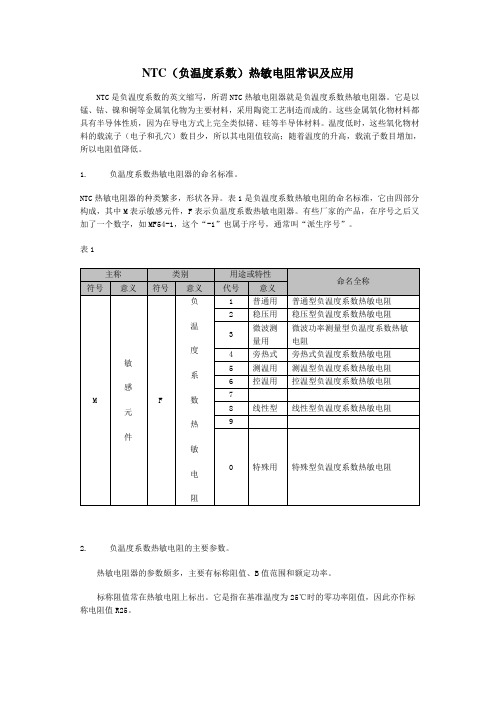
NTC(负温度系数)热敏电阻常识及应用值便增加2.23~4.09%)。
为了简便,可将d25取为-3%/℃,这样估算就十分方便了:在某一温度t℃时热敏电阻所具有的电阻值,等于其前一温度的电阻乘以系数0.97(即100%-3%=97%=0.97)。
例如,某1只MF11型负温度系数热敏电阻器在25℃的阻值为250Ω,那么在26℃时为250Ω×0.97=242.5Ω。
4.负温度系数热敏电阻的典型应用。
第一个应用实例是多点测温仪。
如图1所示。
R1~R5以及表头uA组成测量电桥。
其中,R2、R3是电桥的平衡电阻,R1为起始电阻,R4为满刻度电阻。
当XP未插入XS中时,表头满刻度,起着校正作用。
电位器RP为电桥提供一个稳定的直流电源。
R5与表头uA串联,起修正表头刻度和限制流经表头电流的作用。
Rt1~Rt6为MF11型负温度系数热敏电阻器,分别安装在六个待测温度的场所。
S2为安装在监测室内的切换开关。
当插头XP插入插座XS中后,XS中的Q与A自动分开,操作拨动开关S2便可测出各点的温度,通过表头uA显示读数。
第二个应用实例是温控吊扇。
如图2所示。
R1、Rt和RP构成测温电路。
其中Rt为负温度系数热敏电阻器MF51。
IC为时基集成电路NE555,它与R2、C2构成单稳态延时电路。
继电器K为执行器件,其触点K直接控制吊扇电动机M电源的通断。
C3与VD1~VD4以及T构成降压、整流滤波电路,向温控电路提供所需的直流电源。
当室温低于设定温度值时,Rt的阻值较大,IC的2脚电位高于1/3电源电压,其输出端IC的3脚为低电平,K处于释放状态,吊扇不工作;当室温高于设定温度时,Rt的阻值下降至某一数值,它与RP的串联电路的电压降低到小于1/3电源电压,于是IC的2脚由高电平变为低电平,IC的3脚此时输出高电平,继电器K吸合,吊扇运转。
当室温逐渐下降至设定温度以下时,电路将重复上述过程,从而使室内温度稳定于某一温度值。
- 1、下载文档前请自行甄别文档内容的完整性,平台不提供额外的编辑、内容补充、找答案等附加服务。
- 2、"仅部分预览"的文档,不可在线预览部分如存在完整性等问题,可反馈申请退款(可完整预览的文档不适用该条件!)。
- 3、如文档侵犯您的权益,请联系客服反馈,我们会尽快为您处理(人工客服工作时间:9:00-18:30)。
MF72功率型NTC热敏电阻器
产品简介
MF72功率型NTC热敏电阻器是以过渡金属氧化物为主要原料制成的半导体陶瓷元件。
属于负温度系数热敏电阻器的范畴。
为了避免电子电路中在开机的瞬间产生的浪涌电流,在电源电路中串接一个功率型NTC热敏电阻器,能有效地抑制开机时的浪涌电流,并且在完成抑制浪涌电流作用以后,由于通过其电流的持续作用,功率型NTC热敏电阻器的电阻值将下降到非常小的程度,它消耗的功率可以忽略不计,电压几乎均加到后面设备从而保证线路的正常工作,所以,在电源回路中使用功率型NTC热敏电阻器,是抑制开机浪涌保护电子设备免遭破坏的最为简便而有效的措施。
应用范围
适用于转换电源、开关电源、UPS电源、各类电加热器、电子镇流器、各种电子装置电源电路的保护以及各类显像管、显示器、白炽灯及其它照明灯具的灯丝保护。
特点
1.体积小,功率大,抑制浪涌电流能力强。
2.反应速度快。
3.材料常数(B值)大,残余电阻小。
4.寿命长,可靠性高。
5.系列全,工作范围宽。