AU6805规格书英文版_(正式版)
AU680全自动生化分析系统用户标准化培训手册(V1.0)
按钮条一览..............................................................................................3-7 操作菜单 ...........................................................................................3-8
AU680全自动生化分析系统 用户培训化培训手册 版本1.0
目录
绪言 1-1
本手册常用术语....................................................................... . . . . . . . . . . . . 1-3
开机 2-1
打印常规,急诊及急诊盘中的样本数据 .................................................................................. 6-21 打印试剂空白,定标和质控信息 ............................................................................................ 6-24 批量传输数据到主机/LIS系统................................................................................................. 6-25
TDK EPC 680型号电感说明书
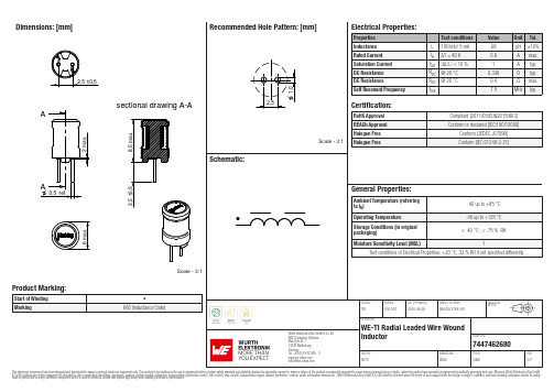
Dimensions: [mm]sectional drawing A-AScale - 3:17447462680744746268074474626807447462680T e m p e r a t u r eT T T 7447462680Cautions and Warnings:The following conditions apply to all goods within the product series of WE-TI of Würth Elektronik eiSos GmbH & Co. KG:General:•This electronic component was designed and manufactured for use in general electronic equipment.•Würth Elektronik must be asked for written approval (following the PPAP procedure) before incorporating the components into any equipment in fields such as military, aerospace, aviation, nuclear control, submarine, transportation (automotive control, train control, ship control), transportation signal, disaster prevention, medical, public information network, etc. where higher safety and reliability are especially required and/or if there is the possibility of direct damage or human injury.•Electronic components that will be used in safety-critical or high-reliability applications, should be pre-evaluated by the customer. •The component is designed and manufactured to be used within the datasheet specified values. If the usage and operation conditions specified in the datasheet are not met, the wire insulation may be damaged or dissolved.•Do not drop or impact the components, the component may be damaged.•Würth Elektronik products are qualified according to international standards, which are listed in each product reliability report. Würth Elektronik does not warrant any customer qualified product characteristics beyond Würth Elektroniks’ specifications, for its validity and sustainability over time.•The customer is responsible for the functionality of their own products. All technical specifications for standard products also apply to customer specific products.Product specific:Soldering:•The solder profile must comply with the technical product specifications. All other profiles will void the warranty.•All other soldering methods are at the customers’ own risk.Cleaning and Washing:•Washing agents used during the production to clean the customer application might damage or change the characteristics of the wire insulation, marking or plating. Washing agents may have a negative effect on the long-term functionality of the product. Potting:•If the product is potted in the costumer application, the potting material might shrink or expand during and after hardening. Shrinking could lead to an incomplete seal, allowing contaminants into the core. Expansion could damage the components. We recommend a manual inspection after potting to avoid these effects. Storage Conditions:• A storage of Würth Elektronik products for longer than 12 months is not recommended. Within other effects, the terminals may suffer degradation, resulting in bad solderability. Therefore, all products shall be used within the period of 12 months based on the day of shipment.•Do not expose the components to direct sunlight.•The storage conditions in the original packaging are defined according to DIN EN 61760-2.•The storage conditions stated in the original packaging apply to the storage time and not to the transportation time of the components. Packaging:•The packaging specifications apply only to purchase orders comprising whole packaging units. If the ordered quantity exceeds or is lower than the specified packaging unit, packaging in accordance with the packaging specifications cannot be ensured. Handling:•Violation of the technical product specifications such as exceeding the nominal rated current will void the warranty.•Applying currents with audio-frequency signals might result in audible noise due to the magnetostrictive material properties. •Due to heavy weight of the components, strong forces and high accelerations might have the effect to damage the electrical connection or to harm the circuit board and will void the warranty.•Please be aware that products provided in bulk packaging may get bent and might lead to derivations from the mechanical manufacturing tolerances mentioned in our datasheet, which is not considered to be a material defect.•The temperature rise of the component must be taken into consideration. The operating temperature is comprised of ambient temperature and temperature rise of the component.The operating temperature of the component shall not exceed the maximum temperature specified.These cautions and warnings comply with the state of the scientific and technical knowledge and are believed to be accurate and reliable.However, no responsibility is assumed for inaccuracies or incompleteness.Würth Elektronik eiSos GmbH & Co. KGEMC & Inductive SolutionsMax-Eyth-Str. 174638 WaldenburgGermanyCHECKED REVISION DATE (YYYY-MM-DD)GENERAL TOLERANCE PROJECTIONMETHODTRi002.0072020-06-25DIN ISO 2768-1mDESCRIPTIONWE-TI Radial Leaded Wire WoundInductor ORDER CODE7447462680SIZE/TYPE BUSINESS UNIT STATUS PAGEImportant NotesThe following conditions apply to all goods within the product range of Würth Elektronik eiSos GmbH & Co. KG:1. General Customer ResponsibilitySome goods within the product range of Würth Elektronik eiSos GmbH & Co. KG contain statements regarding general suitability for certain application areas. These statements about suitability are based on our knowledge and experience of typical requirements concerning the areas, serve as general guidance and cannot be estimated as binding statements about the suitability for a customer application. The responsibility for the applicability and use in a particular customer design is always solely within the authority of the customer. Due to this fact it is up to the customer to evaluate, where appropriate to investigate and decide whether the device with the specific product characteristics described in the product specification is valid and suitable for the respective customer application or not.2. Customer Responsibility related to Specific, in particular Safety-Relevant ApplicationsIt has to be clearly pointed out that the possibility of a malfunction of electronic components or failure before the end of the usual lifetime cannot be completely eliminated in the current state of the art, even if the products are operated within the range of the specifications.In certain customer applications requiring a very high level of safety and especially in customer applications in which the malfunction or failure of an electronic component could endanger human life or health it must be ensured by most advanced technological aid of suitable design of the customer application that no injury or damage is caused to third parties in the event of malfunction or failure of an electronic component. Therefore, customer is cautioned to verify that data sheets are current before placing orders. The current data sheets can be downloaded at .3. Best Care and AttentionAny product-specific notes, cautions and warnings must be strictly observed. Any disregard will result in the loss of warranty.4. Customer Support for Product SpecificationsSome products within the product range may contain substances which are subject to restrictions in certain jurisdictions in order to serve specific technical requirements. Necessary information is available on request. In this case the field sales engineer or the internal sales person in charge should be contacted who will be happy to support in this matter.5. Product R&DDue to constant product improvement product specifications may change from time to time. As a standard reporting procedure of the Product Change Notification (PCN) according to the JEDEC-Standard inform about minor and major changes. In case of further queries regarding the PCN, the field sales engineer or the internal sales person in charge should be contacted. The basic responsibility of the customer as per Section 1 and 2 remains unaffected.6. Product Life CycleDue to technical progress and economical evaluation we also reserve the right to discontinue production and delivery of products. As a standard reporting procedure of the Product Termination Notification (PTN) according to the JEDEC-Standard we will inform at an early stage about inevitable product discontinuance. According to this we cannot guarantee that all products within our product range will always be available. Therefore it needs to be verified with the field sales engineer or the internal sales person in charge about the current product availability expectancy before or when the product for application design-in disposal is considered. The approach named above does not apply in the case of individual agreements deviating from the foregoing for customer-specific products.7. Property RightsAll the rights for contractual products produced by Würth Elektronik eiSos GmbH & Co. KG on the basis of ideas, development contracts as well as models or templates that are subject to copyright, patent or commercial protection supplied to the customer will remain with Würth Elektronik eiSos GmbH & Co. KG. Würth Elektronik eiSos GmbH & Co. KG does not warrant or represent that any license, either expressed or implied, is granted under any patent right, copyright, mask work right, or other intellectual property right relating to any combination, application, or process in which Würth Elektronik eiSos GmbH & Co. KG components or services are used.8. General Terms and ConditionsUnless otherwise agreed in individual contracts, all orders are subject to the current version of the “General Terms and Conditions of Würth Elektronik eiSos Group”, last version available at .Würth Elektronik eiSos GmbH & Co. KGEMC & Inductive SolutionsMax-Eyth-Str. 174638 WaldenburgGermanyCHECKED REVISION DATE (YYYY-MM-DD)GENERAL TOLERANCE PROJECTIONMETHODTRi002.0072020-06-25DIN ISO 2768-1mDESCRIPTIONWE-TI Radial Leaded Wire WoundInductor ORDER CODE7447462680SIZE/TYPE BUSINESS UNIT STATUS PAGE。
MSM51V16805D-70JS中文资料
Output Low Voltage
VOL IOL = 2.0 mA
0 0.4 0 0.4 0 0.4 V
0 V £ VI £ VCC + 0.3 V;
Input Leakage Current ILI All other pins not –10 10 –10 10 –10 10 mA
under test = 0 V
Capacitance
Parameter Input Capacitance (A0 - A8, A9R - A11R)
Input Capacitance (RAS, CAS, WE, OE) Output Capacitance (DQ1 - DQ8)
Symbol
CIN1 CIN2 CI/O
Rating
DESCRIPTION
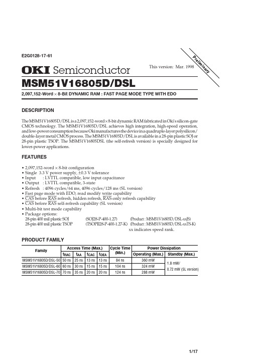
The MSM51V16805D/DSL is a 2,097,152-word ¥ 8-bit dynamic RAM fabricated in Oki's silicon-gate CMOS technology. The MSM51V16805D/DSL achieves high integration, high-speed operation, and low-power consumption because Oki manufactures the device in a quadruple-layer polysilicon/ double-layer metal CMOS process. The MSM51V16805D/DSL is available in a 28-pin plastic SOJ or 28-pin plastic TSOP. The MSM51V16805DSL (the self-refresh version) is specially designed for lower-power applications.
OPB680;OPB680-20;OPB690Z;OPB690;中文规格书,Datasheet资料
/
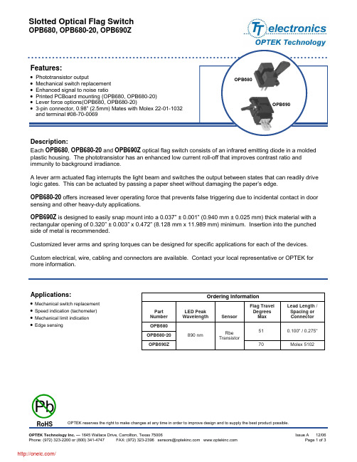
Slotted Optical Flag Switch
OPB680, OPB680-20, OPB690Z
Absolute Maximum Ratings (TA=25°C unless otherwise noted)
Storage & Operating Temperature Range Lead Soldering Temperature [1/16 inch (1.6 mm) from the case for 5 sec. with soldering iron] Input Diode Forward DC Current Peak Forward Current (1 µs pulse width, 300 pps) Reverse DC Voltage Power Dissipation
Output Phototransistor (See OP755 for additional information) V(BR)CEO BVECO ICEO Coupled VSAT IC(ON) Mechanical FOP Cycles Operating Force OPB680, OPB690Z OPB680-20 Operating Cycles 100 K 1.5 20 Saturation Voltage On-State Collector Current 150 600 0.4 µA IF = 10 mA, VCE = 5 V, blocked V IF = 10 mA, IC = 100 µA IF = 10 mA, VCE = 5 V, unblocked Collector-Emitter Breakdown Voltage Emitter-Collector Breakdown Voltage Collector-Emitter Dark Current 30 4.0 100 V V µA IC = 100 µA IEC = 100 µA VCE = 5 V
WM8805数据手册 中英文对照
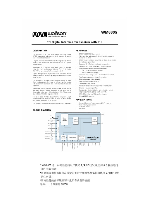
* WM8805是一种高性能的用户模式S / PDIF收发器,支持8个接收通道和1传输通道。
*用晶振或由外部提供高质量的主时钟用来恢复低抖动地由S / PDIF提供的主时钟。
*用高性能的内部锁相环产生所有典型的音频时钟。
一个专用的CLKOU脚提供了一个高驱动时钟输出。
*通过提供一个选项,允许设备仅仅是用来清理(de抖动)接收到的数字音频信号。
*该设备可用于在软件的控制模式或独立的硬件控制模式。
在软件控制方式,支持2-wire和3-wire接口模式。
*状态和错误监测是内置的,结果可以通过控制接口读出,在“标志”模式下通过音频数据接口GPO脚(音频数据和状态标志附加)。
*音频数据接口支持I2S,向左对齐,右对齐和DSP音频格式的字长16位,与采样率从32到192KHz/秒。
*设备提供一个28脚无铅SSOP封装。
1.数字输入插脚有施密特触发器的输入缓冲区。
2.参考表6设备配置在上电或硬件复位。
1.锁相环和数字供电必须始终在供电电压范围0.3 v以内内。
2.锁相环和数字地必须始终在地电压的0.3 v以内。
1. 锁相环和数字供电必须始终在供电电压范围0.3 v以内内。
2. 锁相环和数字地必须始终在地电压的0.3 v以内。
DEVICE DESCRIPTION设备描述INTRODUCTION FEATURES介绍功能•IEC-60958-3 compatible with 32 to 192k frames/s support.IEC - 60958 - 3兼容32到192 k帧/ s的支持•Supports AES-3 data frames.支持aes 3数据帧•Support for reception and transmission of S/PDIF data.支持S / PDIF数据的接收和传输。
•Clock synthesis PLL with reference clock input and low jitter output.时钟合成锁相环根据参考时钟输入并输出低抖晃的信号。
SLA6805M应用手册
(9)FO 端子 异常时的信号输出端子。内部回路请参考右图。 检验出过热时输出(5V)信号。欠压保护电路 动作时是不输出信号。
端子内部等价回路
5
SANKEN ELECTRIC CO., LTD.
此资料可能在不预告的情况下变更
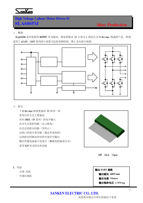
High Voltage 3 phase Motor Driver IC
SLA6805M
2
SANKEN ELECTRIC CO., LTD.
此资料可能在不预告的情况下变更
High Voltage 3 phase Motor Driver IC
SLA680n
自举电容的最佳值是通过驱动方式 (调制方法及输出频率) ; 开关频率 (载波频率) ; 载空率 (Duty) ; 驱动IGBT的门坎输入容量变化。 三相PWM调制方式,120度度通电方式时的选定例为以下。 SLA6805M的情况 条件:自举电流限制电阻=3.3Ω
5.有关保护功能 SLA6805M 的时序表。
Mass Production
6
SANKEN ELECTRIC CO., LTD.
此资料可能在不预告的情况下变更
High Voltage 3 phase Motor Driver IC
SLA6805M
(1)控制电源欠压保护(UVLO)
Mass Production
3
SANKEN ELECTRIC CO., LTD.
此资料可能在不预告的情况下变更
High Voltage 3 phase Motor Driver IC
SLA6805M
(3)VCC1、VCC2 端子
Mass Production
内含前置 IC 的控制电源的端子。请在 VCC1、VCC2 的外部基板上进行连接。为了防止电源浪涌等造成的 误动作, 请在端子附近安装电解电容。 另外, 干扰较多的情况, 请去除和电解电容并连的陶瓷电容。 VCC1 和 VCC2 端子内含欠压保护回路。VCC2 端子电压的保护电压以外的范围进行使用。 (4)COM1、COM2 端子 内含控制前置 IC 的 GND 端子。请在 COM1、COM2 的外部基板上连接。由于此端子的电位的变动会造成误 动作,请充分考虑布线(在没有 Power 电流变动的地方连接,布线长度的缩短等) 。
AU简明操作手册簿(480-680)

简明操作手册(AU全自动生化仪培训资料Ver 1.0)适用机型:贝克曼AU480贝克曼AU680每天工作流程:一、开机前检查;二、开机;三、修改日期索引;四、检查、添加试剂;五、做质控,查看质控结果;六、如有必要,做定标;七、做定标项目的质控,查看结果;八、做标本;九、插入急诊标本;十、查看标本结果;十一、传输标本结果;十二、关机;十三、常见符号;十四、常见报警。
主要按键介绍一、开机前检查1、检查样品配送器、试剂配送器是否泄漏;2、检查清洁剂蠕动泵装置是否泄漏;3、检查主清洁剂的数量并补给;4、检查并清洗样品探针、试剂探针和搅拌棒;二、开机开启ON键,仪器主机以及操作电脑将会自动启动,操作电脑进入“修改日期索引”界面。
三、修改日期索引1、开机后,仪器自动进入以下界面2、点击OK,仪器将自动建立一个日期索引。
注:每天必须修改日期索引,并且每天只能修改一次,如果当天第二次开机,则选择“Current Index”,然后点击OK,仪器将不建立新索引。
四、检查、添加试剂1、点击“主菜单”2、点击“Roution”3、点击“Reagent”点击“Reagent”后,进入以下界面点击“Details”点击“Details”后,进入以下界面点击“Reagent Check”,进入以下界面1、在此查看各试剂剩余测试数,如果哪个试剂少,请添加。
2、点击“Reagent Check”。
1、如果添加的试剂品种很多,就使用第一个选择;2、如果添加试剂品种只有几个,使用第二个;3、第三个选择几乎不用;4、试剂状态显示红色的时候,使用“试剂复位”。
选择好后,点击“Start”,仪器将对试剂进行检查。
五、做质控,查看质控结果1、做质控:将质控品放在“绿色”样品架相应的位置,将“绿色”样品架放置于仪器进样轨道上,点仪器“开始”键。
仪器自动做设置好的项目的质控。
2、查看质控结果:在中文报告系统,点击“质控”“质控图”,即可查看质控结果。
AU680简易操作规程纯中文版

AU680简易操作规程版本:1.01、 开机:如果是正常开机,则只需按仪器上的ON键。
如果是异常关机(如紧急停机),则先按仪器上的RESET,再按ON键。
每次开机时都会提问是否建立一个新的Index,一般选择Yes。
2、 关机:选择键盘END——选择是即可。
仪器及电脑自动关闭,不需要按任何按钮。
3、 试剂检查a) 原装有条码试剂。
点击“主页面”——选择“试剂管理”——进入“试剂管理 ”选择“主”——点击“试剂检查”——点击“详细信息”进入“详细信息”界面观察试剂详细信息 。
b) 非原装无条码试剂。
点击“主页面”——选择“试剂管理”——点击“详细信息”——在“试剂显示”处选“位置”——上下翻页——选择需要放置试剂的位置——点击“位置设置”——选择为“固定试剂”——点击“编辑”编辑相应的试剂名称和相关信息。
——点击“确认”保存并退出。
4、 定标点击“主页面”——选择“样本架申请”——点击“定标”——点击“开始登陆”——选需定标项目及定标模式(RB或CAL)如果选了CAL则RB也一定会被选上——点击“确认”保存并退出。
电解质定标:点击“主页面”——选择“分析仪保养”——选择“ISE保养”——点击“定标”——点击“血清检测启动”,将相应定标液放置在相应位置,点击“开始”5、 样本编程a) 单个样本编程:点击“主页面”——选择“样本架申请”——选择“样品”中的“测试申请”——在“样品号”中确认当前需编辑的样本号 ——确认后点击“开始登陆”后选择项目——点击“登陆”确认——如要编辑下一样本,继续选择项目,然后点击“登陆”——完成项目编程后点击“退出” ——将相应的样本按顺序放在白架子上放在进样区——点击“开始”开始运行。
b) 批量样本编程:点击“主页面”——选择“样品架申请”——选择“样品”中的“测试请求”——在“样品号”中确认当前需编辑的样本号 ——确认后点击“开始登陆”后选择项目——点击“批输入” ——选择“样品数”中输入需批量编程的样本数——点击“OK”后再次确认“样品号”处——确认后点击“退出” ——将相应的样本按顺序放在白架子上放在进样区——点击“开始”开始运行。
- 1、下载文档前请自行甄别文档内容的完整性,平台不提供额外的编辑、内容补充、找答案等附加服务。
- 2、"仅部分预览"的文档,不可在线预览部分如存在完整性等问题,可反馈申请退款(可完整预览的文档不适用该条件!)。
- 3、如文档侵犯您的权益,请联系客服反馈,我们会尽快为您处理(人工客服工作时间:9:00-18:30)。
This specification document applies to R/D(Resolver/Digital) Conversion IC which is mountable on vehicles(automobiles, trains and so on), uses the time-proven R/D Conversion method “Digital Tracking Method” and provides a low-cost and reliable angle(absolute value) detection system designed to accompany with amplitude modulation method brushless resolver(BRX).
Figure 1 Function Configuration Diagram
参考図
ED’N No.
DWG NO.
3
4
5
6
78
9
10
11 12 SHEET
SPC 0 0 9 5 7 4W00 3
T A M A G A W A S E IK I C O . , L T D . J A P参A考N図
参考図 村松 重利 2015/04/13 23:30:38 JST
MODEL No. AU6805
ED’N No. . .
TITLE Smartcoder(AU6805)
Specifications
DWG NO.
34
5
67
8
9 10 11 12 SHEET
SPC009574W00 1 39
T A M A G A W A S E IK I C O . , L T D . J A P参A考N 図
3.2 Physical Feature ································································································31 3.3 Environment Resistance ·······················································································31 4 Quality Assurance ····································································································31 4.1 Warranty of Products···························································································31 4.2 Reliability Test··································································································32 5 Application Note······································································································33 5.1 Input/Output Interface Circuit ················································································33 5.2 System Setting(IC Operating Environment Equipment) ··················································33 5.3 Measure against Noise ·························································································34 5.4 Fail-safe System Architecture ················································································35 5.5 Encoder Application ···························································································36
3.1.2 Functional Composition
R/D conversion functional composition of Digital Tracking Method refers to Figure 1 Function Configuration Diagram.
Sinθ/F(t) BRX
2 Related Document (Referential Drawing)
Attended Figure.3 AU6805 Package Outline Figure
3 Requirements
3.1 Function and Performances
3.1.1 Concept/Feature
θ
R/D Conversion Core
φ
(Digital Tracking Method)
Cosθ/F(t)
F(t)
Excitation Signal
System Control / Input Output Control
Generation
Failure Detection / Built In Self Test(BIST)
The internal constitution of Digital Tracking R/D conversion IC is shown in Figure 2.
VCC
参考図
ED’N No.
DWG NO.
3
4
5
6
78
9
10
11 12 SHEET
SPC 0 0 9 5 7 4W00 2
T A M A G A W A S E IK I C O . , L T D . J A P参A考N図
参考図 村松 重利 2015/04/13 23:30:38 JST
参考図
1 Scope
Digital Tracking Method consists of Digital Signal Processing hardware, sustains and improves the conversion performance (resolution, accuracy, tracking speed, noise immunity, etc.) which is equivalent of AU6803 Twin-PLL method, and achieve a low price. Capable of building an absolute angle detection system with safety and high reliability by enhancing the failure detection function and incorporating a built-in self-test (BIST) function for the R/D conversion and a failure detection function. Simple to use. (All-in-one design; eliminates phase adjustment of exciting signal (i.e. allowable phase angle: ±45 degrees), and others). Quality capable of enduring vehicle-mount applications.